US12021326B2 - Connector having a movable member - Google Patents
Connector having a movable member Download PDFInfo
- Publication number
- US12021326B2 US12021326B2 US17/632,879 US202017632879A US12021326B2 US 12021326 B2 US12021326 B2 US 12021326B2 US 202017632879 A US202017632879 A US 202017632879A US 12021326 B2 US12021326 B2 US 12021326B2
- Authority
- US
- United States
- Prior art keywords
- male
- housing
- female
- movable portion
- terminal
- Prior art date
- Legal status (The legal status is an assumption and is not a legal conclusion. Google has not performed a legal analysis and makes no representation as to the accuracy of the status listed.)
- Active, expires
Links
- 238000000034 method Methods 0.000 claims description 9
- 238000006073 displacement reaction Methods 0.000 claims description 5
- 238000000926 separation method Methods 0.000 claims description 4
- 230000004308 accommodation Effects 0.000 description 19
- 238000003780 insertion Methods 0.000 description 10
- 230000037431 insertion Effects 0.000 description 10
- 230000008878 coupling Effects 0.000 description 4
- 238000010168 coupling process Methods 0.000 description 4
- 238000005859 coupling reaction Methods 0.000 description 4
- 238000002788 crimping Methods 0.000 description 3
- 229920003002 synthetic resin Polymers 0.000 description 3
- 239000000057 synthetic resin Substances 0.000 description 3
- 230000000149 penetrating effect Effects 0.000 description 2
- 238000005452 bending Methods 0.000 description 1
- 230000000694 effects Effects 0.000 description 1
- 239000000463 material Substances 0.000 description 1
- 239000002184 metal Substances 0.000 description 1
- 230000002093 peripheral effect Effects 0.000 description 1
Images


Classifications
-
- H—ELECTRICITY
- H01—ELECTRIC ELEMENTS
- H01R—ELECTRICALLY-CONDUCTIVE CONNECTIONS; STRUCTURAL ASSOCIATIONS OF A PLURALITY OF MUTUALLY-INSULATED ELECTRICAL CONNECTING ELEMENTS; COUPLING DEVICES; CURRENT COLLECTORS
- H01R13/00—Details of coupling devices of the kinds covered by groups H01R12/70 or H01R24/00 - H01R33/00
- H01R13/02—Contact members
- H01R13/193—Means for increasing contact pressure at the end of engagement of coupling part, e.g. zero insertion force or no friction
-
- H—ELECTRICITY
- H01—ELECTRIC ELEMENTS
- H01R—ELECTRICALLY-CONDUCTIVE CONNECTIONS; STRUCTURAL ASSOCIATIONS OF A PLURALITY OF MUTUALLY-INSULATED ELECTRICAL CONNECTING ELEMENTS; COUPLING DEVICES; CURRENT COLLECTORS
- H01R11/00—Individual connecting elements providing two or more spaced connecting locations for conductive members which are, or may be, thereby interconnected, e.g. end pieces for wires or cables supported by the wire or cable and having means for facilitating electrical connection to some other wire, terminal, or conductive member, blocks of binding posts
- H01R11/11—End pieces or tapping pieces for wires, supported by the wire and for facilitating electrical connection to some other wire, terminal or conductive member
-
- H—ELECTRICITY
- H01—ELECTRIC ELEMENTS
- H01R—ELECTRICALLY-CONDUCTIVE CONNECTIONS; STRUCTURAL ASSOCIATIONS OF A PLURALITY OF MUTUALLY-INSULATED ELECTRICAL CONNECTING ELEMENTS; COUPLING DEVICES; CURRENT COLLECTORS
- H01R13/00—Details of coupling devices of the kinds covered by groups H01R12/70 or H01R24/00 - H01R33/00
- H01R13/02—Contact members
- H01R13/10—Sockets for co-operation with pins or blades
- H01R13/11—Resilient sockets
- H01R13/114—Resilient sockets co-operating with pins or blades having a square transverse section
-
- H—ELECTRICITY
- H01—ELECTRIC ELEMENTS
- H01R—ELECTRICALLY-CONDUCTIVE CONNECTIONS; STRUCTURAL ASSOCIATIONS OF A PLURALITY OF MUTUALLY-INSULATED ELECTRICAL CONNECTING ELEMENTS; COUPLING DEVICES; CURRENT COLLECTORS
- H01R13/00—Details of coupling devices of the kinds covered by groups H01R12/70 or H01R24/00 - H01R33/00
- H01R13/02—Contact members
- H01R13/22—Contacts for co-operating by abutting
- H01R13/24—Contacts for co-operating by abutting resilient; resiliently-mounted
- H01R13/2407—Contacts for co-operating by abutting resilient; resiliently-mounted characterized by the resilient means
-
- H—ELECTRICITY
- H01—ELECTRIC ELEMENTS
- H01R—ELECTRICALLY-CONDUCTIVE CONNECTIONS; STRUCTURAL ASSOCIATIONS OF A PLURALITY OF MUTUALLY-INSULATED ELECTRICAL CONNECTING ELEMENTS; COUPLING DEVICES; CURRENT COLLECTORS
- H01R13/00—Details of coupling devices of the kinds covered by groups H01R12/70 or H01R24/00 - H01R33/00
- H01R13/40—Securing contact members in or to a base or case; Insulating of contact members
- H01R13/42—Securing in a demountable manner
-
- H—ELECTRICITY
- H01—ELECTRIC ELEMENTS
- H01R—ELECTRICALLY-CONDUCTIVE CONNECTIONS; STRUCTURAL ASSOCIATIONS OF A PLURALITY OF MUTUALLY-INSULATED ELECTRICAL CONNECTING ELEMENTS; COUPLING DEVICES; CURRENT COLLECTORS
- H01R13/00—Details of coupling devices of the kinds covered by groups H01R12/70 or H01R24/00 - H01R33/00
- H01R13/46—Bases; Cases
- H01R13/516—Means for holding or embracing insulating body, e.g. casing, hoods
-
- H—ELECTRICITY
- H01—ELECTRIC ELEMENTS
- H01R—ELECTRICALLY-CONDUCTIVE CONNECTIONS; STRUCTURAL ASSOCIATIONS OF A PLURALITY OF MUTUALLY-INSULATED ELECTRICAL CONNECTING ELEMENTS; COUPLING DEVICES; CURRENT COLLECTORS
- H01R13/00—Details of coupling devices of the kinds covered by groups H01R12/70 or H01R24/00 - H01R33/00
- H01R13/62—Means for facilitating engagement or disengagement of coupling parts or for holding them in engagement
- H01R13/627—Snap or like fastening
- H01R13/6271—Latching means integral with the housing
- H01R13/6272—Latching means integral with the housing comprising a single latching arm
-
- H—ELECTRICITY
- H01—ELECTRIC ELEMENTS
- H01R—ELECTRICALLY-CONDUCTIVE CONNECTIONS; STRUCTURAL ASSOCIATIONS OF A PLURALITY OF MUTUALLY-INSULATED ELECTRICAL CONNECTING ELEMENTS; COUPLING DEVICES; CURRENT COLLECTORS
- H01R13/00—Details of coupling devices of the kinds covered by groups H01R12/70 or H01R24/00 - H01R33/00
- H01R13/62—Means for facilitating engagement or disengagement of coupling parts or for holding them in engagement
- H01R13/627—Snap or like fastening
- H01R13/6275—Latching arms not integral with the housing
-
- H—ELECTRICITY
- H01—ELECTRIC ELEMENTS
- H01R—ELECTRICALLY-CONDUCTIVE CONNECTIONS; STRUCTURAL ASSOCIATIONS OF A PLURALITY OF MUTUALLY-INSULATED ELECTRICAL CONNECTING ELEMENTS; COUPLING DEVICES; CURRENT COLLECTORS
- H01R13/00—Details of coupling devices of the kinds covered by groups H01R12/70 or H01R24/00 - H01R33/00
- H01R13/62—Means for facilitating engagement or disengagement of coupling parts or for holding them in engagement
- H01R13/639—Additional means for holding or locking coupling parts together, after engagement, e.g. separate keylock, retainer strap
-
- H—ELECTRICITY
- H01—ELECTRIC ELEMENTS
- H01R—ELECTRICALLY-CONDUCTIVE CONNECTIONS; STRUCTURAL ASSOCIATIONS OF A PLURALITY OF MUTUALLY-INSULATED ELECTRICAL CONNECTING ELEMENTS; COUPLING DEVICES; CURRENT COLLECTORS
- H01R13/00—Details of coupling devices of the kinds covered by groups H01R12/70 or H01R24/00 - H01R33/00
- H01R13/02—Contact members
- H01R13/04—Pins or blades for co-operation with sockets
- H01R13/05—Resilient pins or blades
-
- H—ELECTRICITY
- H01—ELECTRIC ELEMENTS
- H01R—ELECTRICALLY-CONDUCTIVE CONNECTIONS; STRUCTURAL ASSOCIATIONS OF A PLURALITY OF MUTUALLY-INSULATED ELECTRICAL CONNECTING ELEMENTS; COUPLING DEVICES; CURRENT COLLECTORS
- H01R13/00—Details of coupling devices of the kinds covered by groups H01R12/70 or H01R24/00 - H01R33/00
- H01R13/02—Contact members
- H01R13/10—Sockets for co-operation with pins or blades
- H01R13/11—Resilient sockets
-
- H—ELECTRICITY
- H01—ELECTRIC ELEMENTS
- H01R—ELECTRICALLY-CONDUCTIVE CONNECTIONS; STRUCTURAL ASSOCIATIONS OF A PLURALITY OF MUTUALLY-INSULATED ELECTRICAL CONNECTING ELEMENTS; COUPLING DEVICES; CURRENT COLLECTORS
- H01R13/00—Details of coupling devices of the kinds covered by groups H01R12/70 or H01R24/00 - H01R33/00
- H01R13/40—Securing contact members in or to a base or case; Insulating of contact members
- H01R13/42—Securing in a demountable manner
- H01R13/436—Securing a plurality of contact members by one locking piece or operation
- H01R13/4361—Insertion of locking piece perpendicular to direction of contact insertion
- H01R13/4362—Insertion of locking piece perpendicular to direction of contact insertion comprising a temporary and a final locking position
-
- H—ELECTRICITY
- H01—ELECTRIC ELEMENTS
- H01R—ELECTRICALLY-CONDUCTIVE CONNECTIONS; STRUCTURAL ASSOCIATIONS OF A PLURALITY OF MUTUALLY-INSULATED ELECTRICAL CONNECTING ELEMENTS; COUPLING DEVICES; CURRENT COLLECTORS
- H01R13/00—Details of coupling devices of the kinds covered by groups H01R12/70 or H01R24/00 - H01R33/00
- H01R13/62—Means for facilitating engagement or disengagement of coupling parts or for holding them in engagement
- H01R13/629—Additional means for facilitating engagement or disengagement of coupling parts, e.g. aligning or guiding means, levers, gas pressure electrical locking indicators, manufacturing tolerances
- H01R13/631—Additional means for facilitating engagement or disengagement of coupling parts, e.g. aligning or guiding means, levers, gas pressure electrical locking indicators, manufacturing tolerances for engagement only
- H01R13/6315—Additional means for facilitating engagement or disengagement of coupling parts, e.g. aligning or guiding means, levers, gas pressure electrical locking indicators, manufacturing tolerances for engagement only allowing relative movement between coupling parts, e.g. floating connection
-
- H—ELECTRICITY
- H01—ELECTRIC ELEMENTS
- H01R—ELECTRICALLY-CONDUCTIVE CONNECTIONS; STRUCTURAL ASSOCIATIONS OF A PLURALITY OF MUTUALLY-INSULATED ELECTRICAL CONNECTING ELEMENTS; COUPLING DEVICES; CURRENT COLLECTORS
- H01R13/00—Details of coupling devices of the kinds covered by groups H01R12/70 or H01R24/00 - H01R33/00
- H01R13/62—Means for facilitating engagement or disengagement of coupling parts or for holding them in engagement
- H01R13/629—Additional means for facilitating engagement or disengagement of coupling parts, e.g. aligning or guiding means, levers, gas pressure electrical locking indicators, manufacturing tolerances
- H01R13/633—Additional means for facilitating engagement or disengagement of coupling parts, e.g. aligning or guiding means, levers, gas pressure electrical locking indicators, manufacturing tolerances for disengagement only
- H01R13/635—Additional means for facilitating engagement or disengagement of coupling parts, e.g. aligning or guiding means, levers, gas pressure electrical locking indicators, manufacturing tolerances for disengagement only by mechanical pressure, e.g. spring force
Definitions
- Patent Document 1 discloses a lever-type connector including female terminals, a housing and a lever.
- the female terminals are connected to male terminals by connecting the housing to a male housing.
- the lever is formed with a cam groove to be engaged with a cam pin formed on the male housing.
- the housing is pulled toward the male housing by a cam action caused by the engagement of the cam pin and the cam groove. In this way, even if connection resistance between the housing and the male housing is generated by generating friction resistance due to resilient restoring forces of the female terminals, a force necessary to connect the housing and the male housing can be reduced.
- the present disclosure is directed to a connector with a female terminal fitting including a resilient contact piece, a female housing for accommodating the female terminal fitting, a male terminal fitting to be connected to the resilient contact piece, a male housing for accommodating the male terminal fitting, the male housing being connected to the female housing, and a movable portion displaceable between a terminal deforming position where the resilient contact piece is resiliently deformed away from the male terminal fitting and a releasing position where the movable portion is disengaged from the resilient contact piece, wherein at least one of the movable portion and the male housing is formed with a slide-contact portion for sliding in contact with the other of the movable portion and the male housing in a connection process of the female housing and the male housing, and the slide-contact portion is inclined to displace the movable portion from the releasing position to the terminal deforming position by sliding in contact with the other of the movable portion and the male housing.
- connection resistance between a female housing and a male housing while preventing the settling of a resilient contact piece of a female terminal fitting.
- FIG. 1 is an exploded perspective view of a connector of one embodiment.
- FIG. 2 is a side view in section showing a state where a retainer is held at a partial locking position and female terminal fittings are inserted in a female housing.
- FIG. 3 is a side view in section showing a state where the retainer is displaced to a full locking position.
- FIG. 4 is a perspective view showing a state where the retainer and a lock arm are assembled with the female housing.
- FIG. 5 is a side view in section showing a state where the retainer is located at a releasing position while a female connector and a male connector are being connected.
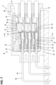
- FIG. 7 is a side view in section showing a state where the retainer is displaced from the terminal deforming position to the releasing position when the female connector and the male connector are properly connected.
- FIG. 8 is a section along A-A of FIG. 6 .
- FIG. 9 is a section along B-B of FIG. 7 .
- the connector of the present disclosure is provided with a female terminal fitting including a resilient contact piece, a female housing for accommodating the female terminal fitting, a male terminal fitting to be connected to the resilient contact piece, a male housing for accommodating the male terminal fitting, the male housing being connected to the female housing, and a movable portion displaceable between a terminal deforming position where the resilient contact piece is resiliently deformed away from the male terminal fitting and a releasing position where the movable portion is disengaged from the resilient contact piece, wherein at least one of the movable portion and the male housing is formed with a slide-contact portion for sliding in contact with the other of the movable portion and the male housing, and the slide-contact portion is inclined to displace the movable portion from the releasing position to the terminal deforming position by sliding in contact with the other of the movable portion and the male housing as connection of the female housing and the male housing proceeds.
- the slide-contact portion can slide in contact with the other of the movable portion and the male housing and the movable portion can be displaced from the releasing position to the terminal deforming position by proceeding with the connection of the female housing and the male housing.
- the resilient contact piece in connecting the female terminal fitting and the male terminal fitting, can be resiliently deformed away from the male terminal fitting in advance.
- the movable portion can be returned to a released state by releasing the sliding contact state of the slide-contact portion and the other of the movable portion and the male housing.
- the movable portion can be returned to a state before resilient deformation and the female terminal fitting and the male terminal fitting can be connected with a proper contact pressure.
- the movable portion preferably includes a deforming portion to be more resiliently deformed according to a displacement from the releasing position to the terminal deforming position.
- the deforming portion is more resiliently deformed according to the displacement of the movable portion from the releasing position to the terminal deforming position.
- the deforming portion is most resiliently deformed. In this way, the movable portion can be reliably displaced from the terminal deforming position to the releasing position.
- the movable portion has both a function to resiliently deform the resilient contact piece away from the male terminal fitting and a function to lock the female housing and the male housing in a connected state. Therefore, the connector of the present disclosure has a smaller number of components as compared to the case where a member for moving the resilient contact piece away from the male terminal fitting and a member for locking the female housing and the male housing in the connected state are separately prepared.
- the movable portion is provided on a retainer for preventing the female terminal fitting from coming out from the female housing.
- the retainer has both a function to resiliently deform the resilient contact piece away from the male terminal fitting and a function to retain the female terminal fitting. Therefore, the connector of the present disclosure has a smaller number of components as compared to the case where a member for moving the resilient contact piece away from the male terminal fitting and a member for retaining the female terminal fitting are separately prepared.
- a left side in FIGS. 2 , 3 , 5 to 7 and 10 is defined as a front side concerning a front-rear direction.
- Upper and lower sides shown in FIGS. 2 , 3 and 5 to 10 are directly defined as upper and lower sides concerning a vertical direction.
- Left and right sides shown in FIGS. 8 and 9 are directly defined as left and right sides concerning a lateral direction.
- a connector of this embodiment includes a female connector F and a male connector M connectable to and separatable from each other as shown in FIG. 1 .
- the female connector F includes a female housing 10 , a plurality of female terminal fittings 20 and a retainer 30 .
- the female housing 10 is made of synthetic resin. As shown in FIG. 1 , the female housing 10 includes a plurality of terminal accommodation chambers 11 for accommodating the female terminal fittings 20 . The terminal accommodation chambers 11 penetrate through the female housing 10 in the front-rear direction.
- the female housing 10 includes an accommodation space 12 for accommodating the retainer 30 .
- the accommodation space 12 communicates with the plurality of terminal accommodation chambers 11 and is open as a slit long in the lateral direction in the upper surface (outer surface) of the female housing 10 .
- the accommodation space 12 is also open in both left and right sides of the female housing 10 .
- a pair of recesses 13 recessed laterally inward are formed at positions adjacent to a front side of the accommodation space 12 in the female housing 10 .
- a first locked portion 14 and a second locked portion 15 are formed on a lower end side of the recess 13 .
- the second locked portion 15 is formed below the first locked portion 14 .
- the first locked portions 14 are claw-like parts to be locked by locking portions 35 when the retainer 30 to be described later is at a partial locking position.
- the second locked portions 15 are claw-like parts to be locked by the locking portions 35 when the retainer 30 to be described later is at a full locking position.
- Inclined portions 16 are formed below the second locked portions 15 in the female housing 10 .
- the inclined portion 16 is inclined downward toward an outer side. The inclined portion 16 extends further rearward than the first and second locked portions 14 , 15 .
- a projection 17 projecting upward is formed on a front end side of the upper surface of the female housing 10 .
- the projection 17 is shaped to become wider in the lateral direction toward an upper side.
- a third locked portion 18 is formed on a rear end side of the upper surface of the projection 17 .
- the third locked portion 18 is a claw-like part to be locked by a lock arm 40 to be described later.
- a covering wall portion 19 is formed on the rear end of the upper surface of the female housing 10 . As shown in FIG. 4 , the covering wall portion 19 covers a rear end side (part on the side of an operating portion 41 ) of the lock arm 40 to be described later.
- the female connector F includes the plurality of female terminal fittings 20 .
- the female terminal fitting 20 has a shape elongated in the front-rear direction as a whole.
- a box portion 21 in the form of a rectangular tube is formed in the front end of the female terminal fitting 20 and a crimping portion 22 in the form of an open barrel to be fixed to the front end of a wire L is formed in the rear end part of the female terminal fitting 20 .
- the rear end of the box portion 21 and the front end of the crimping portion 22 are connected via a coupling portion 23 .
- the rear end of the box portion 21 serves as a hooking portion 24 projecting upward in a stepped manner with respect to an upper edge part of the coupling portion 23 .
- the female terminal fitting 20 includes a resilient contact piece 25 .
- the resilient contact piece 25 is arcuately folded rearward from the front end of a lower plate constituting the box portion 21 and extends rearward.
- the resilient contact piece 25 is resiliently displaceable in the vertical direction (directions toward and away from a receiving portion 26 ) with a folded part connected to the lower plate as a fulcrum.
- the resilient contact piece 25 includes a curved portion 27 curved upward toward the receiving portion 26 , and the upper end of a curved part serves as a contact point portion 28 .
- the resilient contact piece 25 includes a pressure receiving portion 29 .
- the pressure receiving portion 29 is formed to have a folded rear end while being cantilevered to extend obliquely to an upper rear side from the rear end of the curved portion 27 , and disposed in the rear end of the resilient contact piece 25 .
- the rear end of the pressure receiving portion 29 projects further rearward than the rear end (hooking portion 24 ) of the box portion 21 .
- the retainer 30 is made of synthetic resin. As shown in FIG. 1 , the retainer 30 includes a movable portion 31 and a pair of side wall portions (corresponding to a deforming portion of the present invention) 34 .
- the movable portion 31 has a rectangular parallelepiped shape long in the lateral direction.
- the movable portion 31 is formed with a plurality of terminal insertion holes 33 penetrating in the front-rear direction.
- a plurality of retaining portions 36 corresponding to the respective terminal accommodation chambers 11 are formed on lower edge parts of the terminal insertion holes 33 .
- a retainer-side slide-contact portion (slide-contact portion of the present invention) 32 projecting upward is formed on the upper surface of the movable portion 31 .
- a front end side of the retainer-side slide-contact portion 32 is inclined with respect to a connecting direction of the both housings 10 , 50 . Specifically, the front end side of the retainer-side slide-contact portion 32 is inclined downward toward a front side.
- the pair of side wall portions 34 are configured as wall portions on both left and right sides of the retainer 30 , and the front ends thereof extend further forward than the movable portion 31 .
- the claw-like locking portions 35 are formed on the lower ends of the side wall portions 34 .
- the lock arm 40 is in the form of a strip plate.
- the operating portion 41 is formed on the rear end of the lock arm 40 .
- the operating portion 41 is a part to be operated in separating the female connector F and the male connector M.
- a groove portion (not shown) widened in the lateral direction toward an upper side is formed in a front end side of the lock arm 40 .
- This groove portion is shaped to correspond to the projection 17 of the female housing 10 and become wider toward an upper side.
- a second locking portion 42 projecting downward is formed in the rear end of this groove portion.
- a front end portion 43 for contacting the front end of the projection 17 is formed in the front end of this groove portion.
- the male connector M includes a male housing 50 and a plurality of male terminal fittings 60 .
- the male connector M functions as a board connector to be mounted on a circuit board (not shown).
- the male housing 50 is made of synthetic resin.
- the male housing 50 includes a terminal holding portion 51 and a receptacle 52 . Rear end sides of the male terminal fittings 60 are passed through the terminal holding portion 51 in the front-rear direction.
- the receptacle 52 is in the form of a rectangular tube projecting rearward from the outer peripheral edge of the terminal holding portion 51 . As shown in FIG.
- a pair of step portions 54 lower than a laterally central part are formed to sandwich the central part in an upper wall part of an inner surface 53 of the receptacle 52 .
- the step portions 54 extend along the front-rear direction of the receptacle 52 .
- male slide-contact portions (slide-contact portion of the present invention) 55 are formed on the rear ends of the step portions 54 (only the male slide-contact portion 55 on a back side is shown in FIG. 5 ).
- the male slide-contact portion 55 is inclined with respect to the connecting direction of the both housings 10 , 50 . Specifically, the lower surface of the rear end of the male slide-contact portion 55 is inclined upward toward a rear side.
- Lock portions 56 to which the movable portion 31 can be hooked when the respective housings 10 , 50 are properly connected, are formed at positions slightly separated forward from the male slide-contact portions 55 in the step portions 54 .
- the lock portion 56 is a part recessed upward from or open upward in the lower surface of the step portion 43 .
- a jig insertion hole 57 penetrating in the vertical direction is formed in a rear end side of the upper wall of the receptacle 52 .
- the male terminal fitting 60 is shaped by bending a metal bar material into an L shape in a side view.
- the male terminal fitting 60 includes a board connecting portion 62 extending downward from a bent portion 61 and a tab 63 extending forward from the bent portion 61 .
- the male terminal fitting 60 is mounted in the male housing 50 with the tab 63 passed through the terminal holding portion 51 from behind the male housing 50 .
- the board connecting portion 62 is exposed in front of the male housing 50 and connected to the circuit board (not show).
- the tab 63 is accommodated in the receptacle 52 .
- the retainer 30 is mounted into the accommodation space 12 from above the female housing 10 .
- the pair of side wall portions 34 respectively cover the pair of recesses 13 from outside.
- the mounted retainer 30 is held at the partial locking position (not shown) by locking the locking portions 35 to the first locked portions 14 .
- the locking portions 35 of the retainer 30 are hooked to the first locked portions 14 from below, whereby the separation of the retainer 30 from the female housing 10 is restricted.
- the terminal insertion holes 33 correspond to the terminal accommodation chambers 11 and the retaining portions 36 are retracted upward from insertion paths into the terminal accommodation chambers 11 for the female terminal fittings 20 as shown in FIG. 2 .
- the female terminal fittings 20 are inserted into the terminal accommodation chambers 11 from behind the female housing 10 .
- the retainer 30 at the partial locking position is pushed down and displaced to a releasing position (full locking position).
- the retaining portions 36 of the retainer 30 proximately face the box portions 21 (hooking portions 24 ) of the female terminal fittings 20 from behind as shown in FIG. 3 . Therefore, even if a rearward pulling force is applied to the female terminal fitting 20 , the hooking portion 24 is hooked to the retaining portion 36 , whereby the female terminal fitting 20 can be prevented from being withdrawn rearward from the terminal accommodation chamber 11 .
- the movable portion 31 is displaced between a terminal deforming position and the releasing position by receiving an action (action in which the retainer-side slide-contact portion 32 is pushed down by sliding in contact with the male-side slide-contact portions 55 ) from the male housing 50 as described later.
- the movable portion 31 resiliently deforms the resilient contact pieces 25 away from the male terminal fittings 60 when being at the terminal deforming position.
- the movable portion 31 is disengaged from the resilient contact pieces 25 when being at the releasing position.
- the box portion 21 of the incompletely inserted female terminal fitting 20 is located in the accommodation space 12 . Accordingly, if an attempt is made to displace the retainer 30 at the partial locking position downward, the retaining portion 36 of the retainer 30 interferes with the rear end of the box portion 21 in the incompletely inserted state, wherefore the retainer 30 cannot be pushed down to the releasing position (full locking position). By restricting a movement of the retainer 30 in this way, the presence of the incompletely inserted female terminal fitting 20 can be detected.
- the lock arm 40 is assembled with the female housing 10 mounted with the female terminal fittings 20 and the retainer 30 (see also FIG. 4 ).
- the projection 17 of the female housing 10 is inserted into the groove portion (not shown) provided in the front end side of the lock arm 40 .
- the second locking portion 42 faces the projection 17 from behind after riding over the projection 17 from front.
- the front end portion 43 faces the front end of the projection 17 and restricts a rearward movement of the lock arm 40 with respect to the female housing 10 .
- the lock arm 40 prevents the detachment of the retainer 30 by being assembled with the female housing 10 to cover the retainer 30 .
- connection step of the female connector F and the male connector M is described.
- the female housing 10 is fit into the receptacle 52 .
- a connection process as shown in FIG. 5 , if the female housing 10 is inserted into the receptacle 52 to a certain extent (to such an extent that the tabs 63 are at positions slightly before contacting the contact point portions 28 ), the retainer-side slide-contact portion 32 contacts the male-side slide-contact portions 55 .
- the retainer-side slide-contact portion 32 and the male-side slide-contact portions 55 are oblique with respect to the connecting direction, the retainer-side slide-contact portion 32 and the male-side slide-contact portions 55 slide in contact with each other and the movable portion 31 is displaced from the releasing position to the terminal deforming position as the connection of the female housing 10 and the male housing 50 proceeds.
- the locking portions 35 of the retainer 30 slide downward in contact with the inclined portions 16 as shown in FIG. 8 . In this way, the side wall portions 34 of the retainer 30 are more resiliently deformed outward by being pushed outward by the inclined portions 16 .
- the movable portion 31 is held at the terminal deforming position by the retainer-side slide-contact portion 32 contacting the inner surface 53 (specifically, the step portions 54 on the front sides of the male-side slide-contact portions 55 ) of the receptacle 52 from below.
- the retaining portions 36 of the retainer 30 push the pressure receiving portions 29 of the female terminal fittings 20 downward.
- the resilient contact pieces 25 are resiliently deformed to be retracted downward from insertion paths for the tabs 63 in the terminal accommodation chambers 11 (see FIG. 6 ).
- a displacing direction of the resilient contact pieces 25 at this time is a direction intersecting at a right angle to an inserting direction of the tabs 63 into the box portions 21 .
- the connection further proceeds and the resilient contact pieces 25 can be resiliently deformed away from the tabs 63 in connecting the female terminal fittings 20 and the male terminal fittings 60 as shown in FIG. 6 .
- the movable portion 31 is located at the terminal deforming position. In this way, the generation of sliding resistance between the tabs 63 and the resilient contact pieces 25 can be avoided in the process of connecting the female terminal fittings 20 and the male terminal fittings 60 .
- the operating portion 41 of the lock arm 40 is pushed down as shown in FIG. 10 .
- the retainer 30 is pushed down from the releasing position to the terminal deforming position by the lock arm 40 .
- the movable portion 31 comes out from the lock portions 56 and is no longer hooked to the lock portions 56 .
- the female housing 10 can be separated rearward from the male housing 50 .
- the retainer-side slide-contact portion 32 can slide in contact with the male-side slide-contact portions 55 and the movable portion 31 can be displaced from the releasing position to the terminal deforming position by proceeding with the connection of the female housing 10 and the male housing 50 .
- the resilient contact pieces 25 can be resiliently deformed away from the male terminal fittings 60 .
- the movable portion 31 is gradually displaced from the releasing position to the terminal deforming position as the connection of the female housing 10 and the male housing 50 proceeds.
- the resilient contact pieces 25 can be caused to resiliently contact the male terminal fittings 60 if the movable portion 31 is displaced to the releasing position and the resilient contact pieces 25 are released from a resiliently deformed state.
- the movable portion 31 can be returned to a released state by releasing the sliding contact state of the retainer-side slide-contact portion 32 and the male-side slide-contact portions 55 .
- the movable portion 31 can be returned to the state before resilient deformation and the female terminal fittings 20 and the male terminal fittings 60 can be connected with a proper contact pressure.
- the side wall portions 34 are more resiliently deformed according to a displacement of the movable portion 31 from the releasing position to the terminal deforming position.
- the side wall portions 34 are most resiliently deformed. In this way, the movable portion 31 can be reliably displaced from the terminal deforming position to the releasing position.
- the movable portion 31 has both a function to resiliently deform the resilient contact pieces 25 away from the male terminal fittings 60 and a function to lock the female housing 10 and the male housing 50 in the connected state. Therefore, the connector of the present disclosure has a smaller number of components as compared to the case where a member for moving the resilient contact pieces 25 away from the male terminal fittings 60 and a member for locking the female housing 10 and the male housing 50 in the connected state are separately prepared.
- the retainer 30 has both a function to resiliently deform the resilient contact pieces 25 away from the male terminal fittings 60 and a function to retain the female terminal fittings 20 . Therefore, the connector of the present disclosure has a smaller number of components as compared to the case where a member for moving the resilient contact pieces 25 away from the male terminal fittings 60 and a member for retaining the female terminal fittings 20 are separately prepared.
Landscapes
- Details Of Connecting Devices For Male And Female Coupling (AREA)
- Connector Housings Or Holding Contact Members (AREA)
Applications Claiming Priority (3)
| Application Number | Priority Date | Filing Date | Title |
|---|---|---|---|
| JP2019145070A JP7236032B2 (ja) | 2019-08-07 | 2019-08-07 | コネクタ |
| JP2019-145070 | 2019-08-07 | ||
| PCT/JP2020/027762 WO2021024750A1 (fr) | 2019-08-07 | 2020-07-17 | Connecteur |
Publications (2)
| Publication Number | Publication Date |
|---|---|
| US20220278488A1 US20220278488A1 (en) | 2022-09-01 |
| US12021326B2 true US12021326B2 (en) | 2024-06-25 |
Family
ID=74504059
Family Applications (1)
| Application Number | Title | Priority Date | Filing Date |
|---|---|---|---|
| US17/632,879 Active 2041-06-12 US12021326B2 (en) | 2019-08-07 | 2020-07-17 | Connector having a movable member |
Country Status (4)
| Country | Link |
|---|---|
| US (1) | US12021326B2 (fr) |
| JP (1) | JP7236032B2 (fr) |
| CN (1) | CN114175405B (fr) |
| WO (1) | WO2021024750A1 (fr) |
Families Citing this family (3)
| Publication number | Priority date | Publication date | Assignee | Title |
|---|---|---|---|---|
| JP7476808B2 (ja) * | 2021-01-08 | 2024-05-01 | 住友電装株式会社 | コネクタおよびコネクタ装置 |
| US20230029463A1 (en) * | 2021-07-27 | 2023-02-02 | Dell Products L.P. | Battery connector in an information handling system |
| CN116581586B (zh) * | 2023-05-12 | 2023-11-10 | 东莞市思索技术股份有限公司 | 电源连接器 |
Citations (20)
| Publication number | Priority date | Publication date | Assignee | Title |
|---|---|---|---|---|
| JPS61161679A (ja) | 1984-12-28 | 1986-07-22 | アンプ インコ−ポレ−テツド | レセプタクル用電気コネクタ |
| JPS61117471U (fr) | 1985-01-10 | 1986-07-24 | ||
| JPH06325816A (ja) | 1993-05-14 | 1994-11-25 | Amp Japan Ltd | 低挿入力型電気コネクタ |
| US5797772A (en) * | 1996-03-13 | 1998-08-25 | Sumitomo Wiring Systems, Ltd. | Connector provided with a retainer |
| US5830013A (en) * | 1997-03-07 | 1998-11-03 | Yazaki Corporation | Electric connector |
| US5848919A (en) * | 1995-02-22 | 1998-12-15 | Yazaki Corporation | Connector |
| US20060172597A1 (en) * | 2005-02-02 | 2006-08-03 | Sumitomo Wiring Systems, Ltd. | Connector and a method of assembling it |
| JP2006216272A (ja) | 2005-02-01 | 2006-08-17 | Sumitomo Wiring Syst Ltd | コネクタ |
| US7347745B1 (en) * | 2007-01-19 | 2008-03-25 | Tyco Electronics Corporation | Three position electrical connector assembly |
| US20080081504A1 (en) * | 2006-09-29 | 2008-04-03 | Sumitomo Wiring Systems, Ltd. | Connector, connector assembly and a detection terminal |
| US7470156B2 (en) * | 2006-06-02 | 2008-12-30 | Tyco Electronics Amp K.K. | Electrical connector |
| US7500887B2 (en) * | 2006-07-20 | 2009-03-10 | Sumitomo Wiring Systems, Ltd. | Connector and method of assembling it |
| US20110086544A1 (en) * | 2009-10-13 | 2011-04-14 | Sumitomo Wiring Systems, Ltd. | Fluidproof connector |
| US7988502B2 (en) * | 2008-09-16 | 2011-08-02 | Yazaki Corporation | Connector |
| CN103765690A (zh) * | 2011-11-15 | 2014-04-30 | 住友电装株式会社 | 连接器 |
| US9246255B1 (en) * | 2014-09-10 | 2016-01-26 | Yazaki North America, Inc. | Quick slide connector assembly |
| US9318847B2 (en) * | 2014-01-10 | 2016-04-19 | Dai-Ichi Seiko Co., Ltd. | Electric connector |
| US20160240969A1 (en) | 2015-02-16 | 2016-08-18 | Sumitomo Wiring Systems, Ltd. | Lever-type connector |
| US20170365950A1 (en) * | 2016-06-17 | 2017-12-21 | Sumitomo Wiring Systems, Ltd. | Connector with erroneous arrangement identifying portion. |
| US20180205169A1 (en) * | 2015-07-16 | 2018-07-19 | Sumitomo Wiring Systems, Ltd. | Connector |
Family Cites Families (8)
| Publication number | Priority date | Publication date | Assignee | Title |
|---|---|---|---|---|
| JP2000208216A (ja) * | 1999-01-11 | 2000-07-28 | Yazaki Corp | 低挿入力コネクタ |
| JP2002075508A (ja) * | 2000-08-31 | 2002-03-15 | Sumitomo Wiring Syst Ltd | コネクタ |
| JP2002280133A (ja) * | 2001-03-15 | 2002-09-27 | Sumitomo Wiring Syst Ltd | コネクタ |
| KR101143202B1 (ko) * | 2003-06-18 | 2012-05-18 | 에프씨아이 아시아 테크놀로지 피티이 리미티드 | 전기 커넥터 |
| JP2008027760A (ja) * | 2006-07-21 | 2008-02-07 | Sumitomo Wiring Syst Ltd | 嵌合検知機能を備えたコネクタ |
| JP6036661B2 (ja) * | 2013-11-19 | 2016-11-30 | 住友電装株式会社 | 防水コネクタ |
| JP6172207B2 (ja) * | 2015-04-24 | 2017-08-02 | 住友電装株式会社 | コネクタ |
| JP6882941B2 (ja) * | 2017-06-16 | 2021-06-02 | ヒロセ電機株式会社 | 同軸コネクタ組立体 |
-
2019
- 2019-08-07 JP JP2019145070A patent/JP7236032B2/ja active Active
-
2020
- 2020-07-17 WO PCT/JP2020/027762 patent/WO2021024750A1/fr active Application Filing
- 2020-07-17 CN CN202080054117.1A patent/CN114175405B/zh active Active
- 2020-07-17 US US17/632,879 patent/US12021326B2/en active Active
Patent Citations (20)
| Publication number | Priority date | Publication date | Assignee | Title |
|---|---|---|---|---|
| JPS61161679A (ja) | 1984-12-28 | 1986-07-22 | アンプ インコ−ポレ−テツド | レセプタクル用電気コネクタ |
| JPS61117471U (fr) | 1985-01-10 | 1986-07-24 | ||
| JPH06325816A (ja) | 1993-05-14 | 1994-11-25 | Amp Japan Ltd | 低挿入力型電気コネクタ |
| US5848919A (en) * | 1995-02-22 | 1998-12-15 | Yazaki Corporation | Connector |
| US5797772A (en) * | 1996-03-13 | 1998-08-25 | Sumitomo Wiring Systems, Ltd. | Connector provided with a retainer |
| US5830013A (en) * | 1997-03-07 | 1998-11-03 | Yazaki Corporation | Electric connector |
| JP2006216272A (ja) | 2005-02-01 | 2006-08-17 | Sumitomo Wiring Syst Ltd | コネクタ |
| US20060172597A1 (en) * | 2005-02-02 | 2006-08-03 | Sumitomo Wiring Systems, Ltd. | Connector and a method of assembling it |
| US7470156B2 (en) * | 2006-06-02 | 2008-12-30 | Tyco Electronics Amp K.K. | Electrical connector |
| US7500887B2 (en) * | 2006-07-20 | 2009-03-10 | Sumitomo Wiring Systems, Ltd. | Connector and method of assembling it |
| US20080081504A1 (en) * | 2006-09-29 | 2008-04-03 | Sumitomo Wiring Systems, Ltd. | Connector, connector assembly and a detection terminal |
| US7347745B1 (en) * | 2007-01-19 | 2008-03-25 | Tyco Electronics Corporation | Three position electrical connector assembly |
| US7988502B2 (en) * | 2008-09-16 | 2011-08-02 | Yazaki Corporation | Connector |
| US20110086544A1 (en) * | 2009-10-13 | 2011-04-14 | Sumitomo Wiring Systems, Ltd. | Fluidproof connector |
| CN103765690A (zh) * | 2011-11-15 | 2014-04-30 | 住友电装株式会社 | 连接器 |
| US9318847B2 (en) * | 2014-01-10 | 2016-04-19 | Dai-Ichi Seiko Co., Ltd. | Electric connector |
| US9246255B1 (en) * | 2014-09-10 | 2016-01-26 | Yazaki North America, Inc. | Quick slide connector assembly |
| US20160240969A1 (en) | 2015-02-16 | 2016-08-18 | Sumitomo Wiring Systems, Ltd. | Lever-type connector |
| US20180205169A1 (en) * | 2015-07-16 | 2018-07-19 | Sumitomo Wiring Systems, Ltd. | Connector |
| US20170365950A1 (en) * | 2016-06-17 | 2017-12-21 | Sumitomo Wiring Systems, Ltd. | Connector with erroneous arrangement identifying portion. |
Non-Patent Citations (1)
| Title |
|---|
| International Search Report dated Aug. 11, 2020 for WO 2021/024750 A1 (4 pages). |
Also Published As
| Publication number | Publication date |
|---|---|
| US20220278488A1 (en) | 2022-09-01 |
| JP2021026927A (ja) | 2021-02-22 |
| CN114175405B (zh) | 2023-11-28 |
| WO2021024750A1 (fr) | 2021-02-11 |
| JP7236032B2 (ja) | 2023-03-09 |
| CN114175405A (zh) | 2022-03-11 |
Similar Documents
| Publication | Publication Date | Title |
|---|---|---|
| US12021326B2 (en) | Connector having a movable member | |
| US6244880B1 (en) | Low-insertion force connector | |
| US11848519B2 (en) | Connector | |
| US10038279B2 (en) | Connector assembly | |
| US9755363B2 (en) | Connector assembly | |
| US8998626B2 (en) | Connector and connector assembly | |
| US9793647B2 (en) | Connector assembly | |
| JP4304474B2 (ja) | コネクタ | |
| US10944198B2 (en) | Connector | |
| JP4274570B2 (ja) | コネクタ | |
| US11114801B2 (en) | Connector | |
| US20090104808A1 (en) | Connector | |
| US11955745B2 (en) | Female connector and connector | |
| CN111725652B (zh) | 连接器 | |
| US11133622B2 (en) | Connector with connection detection member | |
| WO2021024751A1 (fr) | Connecteur | |
| US20230352869A1 (en) | Connector | |
| US11784431B2 (en) | Connector with terminal fitting and lock arm | |
| JP7389407B2 (ja) | カードエッジコネクタ | |
| JP2012190629A (ja) | コネクタ | |
| JP2023092966A (ja) | コネクタ | |
| CN118073886A (zh) | 连接器 | |
| CN116191095A (zh) | 连接器 | |
| JPH097677A (ja) | コネクタ及びその端子金具取り外し方法 |
Legal Events
| Date | Code | Title | Description |
|---|---|---|---|
| AS | Assignment |
Owner name: SUMITOMO ELECTRIC INDUSTRIES, LTD., JAPAN Free format text: ASSIGNMENT OF ASSIGNORS INTEREST;ASSIGNORS:MIYAMURA, TETSUYA;KOBAYASHI, YUTAKA;KOBAYASHI, HIROKI;AND OTHERS;SIGNING DATES FROM 20211222 TO 20220124;REEL/FRAME:058887/0963 Owner name: SUMITOMO WIRING SYSTEMS, LTD., JAPAN Free format text: ASSIGNMENT OF ASSIGNORS INTEREST;ASSIGNORS:MIYAMURA, TETSUYA;KOBAYASHI, YUTAKA;KOBAYASHI, HIROKI;AND OTHERS;SIGNING DATES FROM 20211222 TO 20220124;REEL/FRAME:058887/0963 Owner name: AUTONETWORKS TECHNOLOGIES, LTD., JAPAN Free format text: ASSIGNMENT OF ASSIGNORS INTEREST;ASSIGNORS:MIYAMURA, TETSUYA;KOBAYASHI, YUTAKA;KOBAYASHI, HIROKI;AND OTHERS;SIGNING DATES FROM 20211222 TO 20220124;REEL/FRAME:058887/0963 |
|
| STPP | Information on status: patent application and granting procedure in general |
Free format text: DOCKETED NEW CASE - READY FOR EXAMINATION |
|
| STPP | Information on status: patent application and granting procedure in general |
Free format text: NOTICE OF ALLOWANCE MAILED -- APPLICATION RECEIVED IN OFFICE OF PUBLICATIONS |
|
| STPP | Information on status: patent application and granting procedure in general |
Free format text: PUBLICATIONS -- ISSUE FEE PAYMENT VERIFIED |
|
| STCF | Information on status: patent grant |
Free format text: PATENTED CASE |