US11906214B2 - Compressor cooling - Google Patents
Compressor cooling Download PDFInfo
- Publication number
- US11906214B2 US11906214B2 US17/063,248 US202017063248A US11906214B2 US 11906214 B2 US11906214 B2 US 11906214B2 US 202017063248 A US202017063248 A US 202017063248A US 11906214 B2 US11906214 B2 US 11906214B2
- Authority
- US
- United States
- Prior art keywords
- refrigerant
- compressor
- compressing
- pressure side
- scroll
- Prior art date
- Legal status (The legal status is an assumption and is not a legal conclusion. Google has not performed a legal analysis and makes no representation as to the accuracy of the status listed.)
- Active, expires
Links
- 238000001816 cooling Methods 0.000 title description 21
- 239000003507 refrigerant Substances 0.000 claims abstract description 168
- 238000007906 compression Methods 0.000 claims abstract description 119
- 230000006835 compression Effects 0.000 claims abstract description 117
- 238000000034 method Methods 0.000 claims abstract description 12
- 238000007599 discharging Methods 0.000 claims abstract description 9
- 239000000314 lubricant Substances 0.000 claims description 33
- 239000012530 fluid Substances 0.000 claims description 25
- 238000004891 communication Methods 0.000 claims description 14
- 230000007704 transition Effects 0.000 claims description 4
- 238000005057 refrigeration Methods 0.000 description 13
- 238000013461 design Methods 0.000 description 6
- CURLTUGMZLYLDI-UHFFFAOYSA-N Carbon dioxide Chemical compound O=C=O CURLTUGMZLYLDI-UHFFFAOYSA-N 0.000 description 3
- 230000008859 change Effects 0.000 description 3
- 230000000737 periodic effect Effects 0.000 description 3
- 230000009466 transformation Effects 0.000 description 3
- 230000008901 benefit Effects 0.000 description 2
- 229910002092 carbon dioxide Inorganic materials 0.000 description 2
- 230000008878 coupling Effects 0.000 description 2
- 238000010168 coupling process Methods 0.000 description 2
- 238000005859 coupling reaction Methods 0.000 description 2
- 230000000694 effects Effects 0.000 description 2
- 230000020169 heat generation Effects 0.000 description 2
- 230000001050 lubricating effect Effects 0.000 description 2
- 238000005086 pumping Methods 0.000 description 2
- 230000009467 reduction Effects 0.000 description 2
- 230000004075 alteration Effects 0.000 description 1
- 239000001569 carbon dioxide Substances 0.000 description 1
- 230000001419 dependent effect Effects 0.000 description 1
- 238000000605 extraction Methods 0.000 description 1
- 231100001261 hazardous Toxicity 0.000 description 1
- 239000007788 liquid Substances 0.000 description 1
- 230000004048 modification Effects 0.000 description 1
- 238000012986 modification Methods 0.000 description 1
- 230000008569 process Effects 0.000 description 1
- 230000001360 synchronised effect Effects 0.000 description 1
- 238000012546 transfer Methods 0.000 description 1
- 230000032258 transport Effects 0.000 description 1
Images


Classifications
-
- F—MECHANICAL ENGINEERING; LIGHTING; HEATING; WEAPONS; BLASTING
- F25—REFRIGERATION OR COOLING; COMBINED HEATING AND REFRIGERATION SYSTEMS; HEAT PUMP SYSTEMS; MANUFACTURE OR STORAGE OF ICE; LIQUEFACTION SOLIDIFICATION OF GASES
- F25B—REFRIGERATION MACHINES, PLANTS OR SYSTEMS; COMBINED HEATING AND REFRIGERATION SYSTEMS; HEAT PUMP SYSTEMS
- F25B31/00—Compressor arrangements
- F25B31/006—Cooling of compressor or motor
-
- F—MECHANICAL ENGINEERING; LIGHTING; HEATING; WEAPONS; BLASTING
- F04—POSITIVE - DISPLACEMENT MACHINES FOR LIQUIDS; PUMPS FOR LIQUIDS OR ELASTIC FLUIDS
- F04C—ROTARY-PISTON, OR OSCILLATING-PISTON, POSITIVE-DISPLACEMENT MACHINES FOR LIQUIDS; ROTARY-PISTON, OR OSCILLATING-PISTON, POSITIVE-DISPLACEMENT PUMPS
- F04C18/00—Rotary-piston pumps specially adapted for elastic fluids
- F04C18/02—Rotary-piston pumps specially adapted for elastic fluids of arcuate-engagement type, i.e. with circular translatory movement of co-operating members, each member having the same number of teeth or tooth-equivalents
- F04C18/0207—Rotary-piston pumps specially adapted for elastic fluids of arcuate-engagement type, i.e. with circular translatory movement of co-operating members, each member having the same number of teeth or tooth-equivalents both members having co-operating elements in spiral form
- F04C18/0215—Rotary-piston pumps specially adapted for elastic fluids of arcuate-engagement type, i.e. with circular translatory movement of co-operating members, each member having the same number of teeth or tooth-equivalents both members having co-operating elements in spiral form where only one member is moving
-
- F—MECHANICAL ENGINEERING; LIGHTING; HEATING; WEAPONS; BLASTING
- F04—POSITIVE - DISPLACEMENT MACHINES FOR LIQUIDS; PUMPS FOR LIQUIDS OR ELASTIC FLUIDS
- F04C—ROTARY-PISTON, OR OSCILLATING-PISTON, POSITIVE-DISPLACEMENT MACHINES FOR LIQUIDS; ROTARY-PISTON, OR OSCILLATING-PISTON, POSITIVE-DISPLACEMENT PUMPS
- F04C29/00—Component parts, details or accessories of pumps or pumping installations, not provided for in groups F04C18/00 - F04C28/00
- F04C29/04—Heating; Cooling; Heat insulation
-
- F—MECHANICAL ENGINEERING; LIGHTING; HEATING; WEAPONS; BLASTING
- F04—POSITIVE - DISPLACEMENT MACHINES FOR LIQUIDS; PUMPS FOR LIQUIDS OR ELASTIC FLUIDS
- F04C—ROTARY-PISTON, OR OSCILLATING-PISTON, POSITIVE-DISPLACEMENT MACHINES FOR LIQUIDS; ROTARY-PISTON, OR OSCILLATING-PISTON, POSITIVE-DISPLACEMENT PUMPS
- F04C18/00—Rotary-piston pumps specially adapted for elastic fluids
- F04C18/02—Rotary-piston pumps specially adapted for elastic fluids of arcuate-engagement type, i.e. with circular translatory movement of co-operating members, each member having the same number of teeth or tooth-equivalents
- F04C18/0207—Rotary-piston pumps specially adapted for elastic fluids of arcuate-engagement type, i.e. with circular translatory movement of co-operating members, each member having the same number of teeth or tooth-equivalents both members having co-operating elements in spiral form
- F04C18/0246—Details concerning the involute wraps or their base, e.g. geometry
- F04C18/0253—Details concerning the base
- F04C18/0261—Details of the ports, e.g. location, number, geometry
-
- F—MECHANICAL ENGINEERING; LIGHTING; HEATING; WEAPONS; BLASTING
- F04—POSITIVE - DISPLACEMENT MACHINES FOR LIQUIDS; PUMPS FOR LIQUIDS OR ELASTIC FLUIDS
- F04C—ROTARY-PISTON, OR OSCILLATING-PISTON, POSITIVE-DISPLACEMENT MACHINES FOR LIQUIDS; ROTARY-PISTON, OR OSCILLATING-PISTON, POSITIVE-DISPLACEMENT PUMPS
- F04C23/00—Combinations of two or more pumps, each being of rotary-piston or oscillating-piston type, specially adapted for elastic fluids; Pumping installations specially adapted for elastic fluids; Multi-stage pumps specially adapted for elastic fluids
- F04C23/008—Hermetic pumps
-
- F—MECHANICAL ENGINEERING; LIGHTING; HEATING; WEAPONS; BLASTING
- F04—POSITIVE - DISPLACEMENT MACHINES FOR LIQUIDS; PUMPS FOR LIQUIDS OR ELASTIC FLUIDS
- F04C—ROTARY-PISTON, OR OSCILLATING-PISTON, POSITIVE-DISPLACEMENT MACHINES FOR LIQUIDS; ROTARY-PISTON, OR OSCILLATING-PISTON, POSITIVE-DISPLACEMENT PUMPS
- F04C29/00—Component parts, details or accessories of pumps or pumping installations, not provided for in groups F04C18/00 - F04C28/00
- F04C29/02—Lubrication; Lubricant separation
- F04C29/025—Lubrication; Lubricant separation using a lubricant pump
-
- F—MECHANICAL ENGINEERING; LIGHTING; HEATING; WEAPONS; BLASTING
- F04—POSITIVE - DISPLACEMENT MACHINES FOR LIQUIDS; PUMPS FOR LIQUIDS OR ELASTIC FLUIDS
- F04C—ROTARY-PISTON, OR OSCILLATING-PISTON, POSITIVE-DISPLACEMENT MACHINES FOR LIQUIDS; ROTARY-PISTON, OR OSCILLATING-PISTON, POSITIVE-DISPLACEMENT PUMPS
- F04C29/00—Component parts, details or accessories of pumps or pumping installations, not provided for in groups F04C18/00 - F04C28/00
- F04C29/04—Heating; Cooling; Heat insulation
- F04C29/045—Heating; Cooling; Heat insulation of the electric motor in hermetic pumps
-
- F—MECHANICAL ENGINEERING; LIGHTING; HEATING; WEAPONS; BLASTING
- F25—REFRIGERATION OR COOLING; COMBINED HEATING AND REFRIGERATION SYSTEMS; HEAT PUMP SYSTEMS; MANUFACTURE OR STORAGE OF ICE; LIQUEFACTION SOLIDIFICATION OF GASES
- F25B—REFRIGERATION MACHINES, PLANTS OR SYSTEMS; COMBINED HEATING AND REFRIGERATION SYSTEMS; HEAT PUMP SYSTEMS
- F25B31/00—Compressor arrangements
- F25B31/002—Lubrication
-
- F—MECHANICAL ENGINEERING; LIGHTING; HEATING; WEAPONS; BLASTING
- F25—REFRIGERATION OR COOLING; COMBINED HEATING AND REFRIGERATION SYSTEMS; HEAT PUMP SYSTEMS; MANUFACTURE OR STORAGE OF ICE; LIQUEFACTION SOLIDIFICATION OF GASES
- F25B—REFRIGERATION MACHINES, PLANTS OR SYSTEMS; COMBINED HEATING AND REFRIGERATION SYSTEMS; HEAT PUMP SYSTEMS
- F25B41/00—Fluid-circulation arrangements
- F25B41/40—Fluid line arrangements
-
- F—MECHANICAL ENGINEERING; LIGHTING; HEATING; WEAPONS; BLASTING
- F04—POSITIVE - DISPLACEMENT MACHINES FOR LIQUIDS; PUMPS FOR LIQUIDS OR ELASTIC FLUIDS
- F04C—ROTARY-PISTON, OR OSCILLATING-PISTON, POSITIVE-DISPLACEMENT MACHINES FOR LIQUIDS; ROTARY-PISTON, OR OSCILLATING-PISTON, POSITIVE-DISPLACEMENT PUMPS
- F04C2240/00—Components
- F04C2240/20—Rotors
-
- F—MECHANICAL ENGINEERING; LIGHTING; HEATING; WEAPONS; BLASTING
- F25—REFRIGERATION OR COOLING; COMBINED HEATING AND REFRIGERATION SYSTEMS; HEAT PUMP SYSTEMS; MANUFACTURE OR STORAGE OF ICE; LIQUEFACTION SOLIDIFICATION OF GASES
- F25B—REFRIGERATION MACHINES, PLANTS OR SYSTEMS; COMBINED HEATING AND REFRIGERATION SYSTEMS; HEAT PUMP SYSTEMS
- F25B2400/00—General features or devices for refrigeration machines, plants or systems, combined heating and refrigeration systems or heat-pump systems, i.e. not limited to a particular subgroup of F25B
- F25B2400/07—Details of compressors or related parts
-
- F—MECHANICAL ENGINEERING; LIGHTING; HEATING; WEAPONS; BLASTING
- F25—REFRIGERATION OR COOLING; COMBINED HEATING AND REFRIGERATION SYSTEMS; HEAT PUMP SYSTEMS; MANUFACTURE OR STORAGE OF ICE; LIQUEFACTION SOLIDIFICATION OF GASES
- F25B—REFRIGERATION MACHINES, PLANTS OR SYSTEMS; COMBINED HEATING AND REFRIGERATION SYSTEMS; HEAT PUMP SYSTEMS
- F25B2500/00—Problems to be solved
- F25B2500/16—Lubrication
Definitions
- the present disclosure relates to a compressor, in particular a scroll compressor having improved cooling, wherein such compressor could be used, for example, in refrigeration systems.
- a compressor is an apparatus, which reduces the volume of a fluid by increasing the pressure of the fluid.
- the fluid is a gas.
- the compressors are used, for example, in refrigeration systems.
- a refrigerant is circulated through a refrigeration cycle. Upon circulation, the refrigerant undergoes changes in thermodynamic properties in different parts of the refrigeration system and transports heat from one part of the refrigeration system to another part of the refrigeration system.
- the refrigerant is a fluid, i.e. a liquid or a vapor or gas.
- refrigerants may be artificial refrigerants like fluorocarbons.
- CO 2 which is a non-artificial refrigerant, has become more and more important, because it is non-hazardous to the environment.
- a compressor comprises at least a suction port, a discharge port, a means for compressing, and a motor.
- the compressor receives the fluid, which is to be compressed.
- the fluid is a refrigerant.
- the fluid usually is in a gaseous or vapor state.
- the means for compressing is used for compressing the fluid from an initial pressure, for example, the pressure the fluid has at the suction port, to a desired discharge pressure.
- the means for compressing may define a compression chamber, which is a closed volume, in which a portion of the refrigerant will be compressed. Afterwards, the compressed fluid is discharged at the discharge port.
- the operation of the compressor is actuated by the motor.
- the motor may be operatively coupled to the means for compressing.
- the motor and the parts of the compression chamber are lubricated by a lubricant, for example an oil.
- the compressor will heat up under load. On the one side, this is because of heat losses caused by the motor and the friction between the actuated parts of the compressor as well as the lubricant.
- the compression of the refrigerant causes the temperature of the refrigerant to rise, which also affects the temperature of the parts, which are in contact to the refrigerant, for example, the means for compressing or the lubricant. If the temperature of the compressor will get too high, the operation of the compressor may be negatively affected. For example, the refrigerant may be discharged at a temperature, which is too high, or the efficiency of the compressor may be reduced. Further, it is also possible that parts of the compressor may be damaged, for example caused by increased friction as a result of disrupted lubricant supply.
- the compressor with cooling according to the invention uses the refrigerant, which is received from the compressor suction at a low temperature, for cooling.
- a compressor according to the invention comprises a suction port, which is configured to receive a refrigerant, in particular, from a refrigeration cycle.
- the suction port may be connected to at least one other component of the refrigeration cycle, from which the suction port receives the refrigerant.
- the suction port may be connected to a heat accepting heat exchanger, which is sometimes referred to as evaporator.
- the connection may be a direct connection or an indirect connection. When the suction port is directly connected to the at least one other component of the refrigeration cycle, there is no other component between the suction port and the at least one other component.
- the connection may be realized, for example, by ease of a tube, a line, or a hose.
- an additional component may be connected between the suction port and the at least one other component.
- the compressor comprises a means for compressing, which is configured for compressing the refrigerant.
- the means for compressing preferably defines at least one compression chamber, in which the refrigerant will be compressed.
- the means for compressing may comprise at least one movable element.
- the movable element may be configured for changing the volume of the at least one compression chamber. Changing said volume may include increasing and/or reducing the volume. A reduction of the volume may cause a compression of the refrigerant inside the volume.
- the means for compressing preferably comprises at least one inlet configured for receiving the refrigerant and one outlet for ejecting at least a portion of the refrigerant after compression.
- the inlet of the means for compressing is in fluid communication with the suction port and is configured to receive the refrigerant, which enters the compressor at the suction port.
- the outlet of the means for compressing is in fluid communication with the discharge port and is configured to eject the compressed refrigerant from the means for compressing.
- the outlet may comprise a valve. Such a valve may prevent the ejected refrigerant from flowing back to the means for compressing.
- the motion of the at least one movable element causes at least a portion of the refrigerant to flow from the inlet of the means for compressing into the at least one compression chamber and causes compression of the refrigerant inside the at least one compression chamber. Further, the motion of the at least one movable element causes an ejection of at least a portion of the compressed refrigerant from the means for compressing via the outlet.
- the compressor comprises a discharge port, which is configured for discharging at least a portion of the compressed refrigerant from the compressor.
- the discharge port is in fluid communication with the outlet of the means for compressing.
- the discharge port may be connected to another component of the refrigeration cycle, for example a heat rejection heat exchanger.
- the connection may be a direct connection or an indirect connection. When the discharge port is connected to the at least one other component of the refrigeration cycle directly, there is no other component between the discharge port and the at least one other component.
- the connection may be realized, for example, by ease of a tube, a line, or a hose.
- an additional component may be connected between the discharge port and the at least one other component.
- the compressor comprises a motor.
- the motor may be used for actuating the compressor, in particular the means for compressing.
- the motor may actuate the at least one movable element of the means for compressing.
- the means for compressing comprises an opening for extracting a portion of the refrigerant from the at least one compression chamber and supplying the extracted portion of the refrigerant to the motor.
- the supplying could be supported by various means.
- the extracted portion of the refrigerant could be supplied to the motor by piping the extracted portion of the refrigerant to the location of the motor inside the compressor.
- the piping may achieve that the extracted portion of the refrigerant circulates around the motor.
- the portion of the refrigerant may be extracted from the at least one compression chamber by pumping the portion of the refrigerant through the opening. Thereby, the pumping may be performed by the at least one movable element of the means for compressing. This has the advantage that no additional components, such as pumps, are needed for the cooling, which is provided by to the invention.
- the opening for extracting the portion of the refrigerant may be located at any position inside the means for compressing, which is suitable for extracting the portion of the refrigerant.
- a suitable position may be any position at which the opening will be in fluid communication with the refrigerant for at least a portion of time.
- the portion of the refrigerant may be extracted at any time before or during the compression process, depending on the position of the opening.
- the portion of the refrigerant may, however, be preferred to extract the portion of the refrigerant from the at least one compression chamber before the compression starts or at an early stage of the compression.
- the at least one compression chamber receives the refrigerant form the suction port of the compressor and will undergo changes in its volume, which will cause the refrigerant inside the at least one compression chamber to be compressed.
- the portion of the refrigerant, which is extracted from the means for compressing may be extracted from the at least one compression chamber at a time at which the compression chamber is closed, but the compression has not yet started.
- the extracted portion of the refrigerant has a relatively low temperature.
- the temperature of the extracted portion of the refrigerant may be equal to or slightly higher than the temperature the refrigerant has when it is received at the suction port of the compressor.
- the temperature of the extracted portion of the refrigerant is, in general, lower than the temperature of the components of the compressor, the temperature of the extracted portion of the refrigerant is suitable for cooling the motor of the compressor.
- the above-mentioned problem of heat generation in the compressor is addressed by providing cooling of the compressor.
- other parts of the compressor for example a lubricant reservoir, may also be cooled by the refrigerant. This may further improve the cooling of the compressor and solve the problem of heat generation in the compressor.
- the cooling effect may be dependent on the amount of refrigerant, which is extracted from the at least one compression chamber.
- 5 to 50 volume percent of the amount of refrigerant, which is received by the at least one compression chamber, may be extracted via the opening.
- the extracted portion of the refrigerant may not only be used for cooling the motor.
- the compressor comprises a lubricant reservoir configured for lubricating various parts of the compressor
- the extracted portion of the refrigerant may additionally be supplied to the lubricant reservoir for cooling the lubricant.
- the lubricant may be an oil.
- the lubricant reservoir may comprise a sump, which is configured for collecting excess lubricant and may be used as a source for supplying the lubricant. Further, the lubricant reservoir may comprise a means for supplying the lubricant to other parts inside the compressor, for example, a pump. In another example, the lubricant reservoir may be configured to provide the lubricant to other parts inside the compressor passively, for example, by allowing another part of the compressor to take the lubricant from the lubricant reservoir. For example, a crankshaft, which may connect the motor to the means for compressing, may at least partially penetrate the lubricant sump and will be moistened by the lubricant.
- the means for compressing may be a scroll set.
- the compressor may be referred to as scroll compressor.
- the scroll compressor comprises at least two scroll plates. In most common applications, two scroll plates are used.
- the at least one movable element of the means for compressing is formed by at least one of the scroll plates.
- the scroll plates are moved relatively to each other.
- This motion may be a periodic motion.
- a first scroll plate of the two scroll plates may be a stationary scroll plate and a second scroll plate of the two scroll plates may be moved relatively to the stationary scroll plate.
- the second scroll plate may be moved in an eccentric orbit around the stationary scroll plate.
- the second scroll plate is moved without rotation relatively to the stationary scroll plate and the center of the orbit is not the same as the center of the stationary scroll plate.
- the second scroll plate is referred to as orbiting scroll plate in this case.
- it is also possible that the two scroll plates are moveable and are co-rotating in a synchronous motion but with offset centers of rotation.
- the scroll plates of the scroll compressor each comprise a base plate and a spiral wrap.
- the base plate may be disk-shaped and the spiral wrap may protrude on the surface on one side of the disk-shaped plate.
- Each spiral wrap defines an involute curve, which has the form of a spiral.
- various forms of spirals may be used.
- the spiral wraps may be symmetrical, but in some other embodiments, the spiral wraps may be asymmetrical.
- the spirals of the two scroll plates comprise a substantially similar curvature.
- the spirals of the two scroll plates each comprise a different curvature.
- at least one of the spirals may be an Archimedean spiral.
- the scroll set of the compressor is formed by stacking the disk-shaped scroll plates. Thereby, their conjugate spiral wraps are interleaved. Upon interleaving the spiral wraps of the respective scroll plates, the spiral wraps contact each other at several points along the flanks of the spirals as well as the opposing base plates. Thereby, the spiral wraps form one or more compression chambers.
- a compression chamber is a closed volume, which is surrounded by the flanks of the interleaved spiral wraps and the base plates. Hence, the compression chambers are separated volumes inside the spiral wraps. Their volume is limited by the flanks of the spiral wraps and the opposing base plates. Further, the volume of the compression chambers is changed during the compression by the relative motion of the scroll plates.
- the one or more compression chambers are formed between the interleaved spiral wraps.
- the compression chambers change their location and move radially from an outermost location between the interleaved spiral wraps to the center of the interleaved spiral wraps.
- the compression chambers are generated at the radially outermost locations between the spiral wraps and are transformed, by ease of further relative motion of the scroll plates, to compression chambers, which are located at a radially inner location between the spiral wraps.
- the transformation of the outermost compression chambers to the inner compression chambers is continuous.
- a compression chamber is formed at the outside of the spiral wraps when parts of the spiral depart from one another.
- the end of the involute curve of the spiral wrap of one of the two scroll plates is in contact with the involute curve of the spiral wrap of the second scroll plate.
- the scroll plates move relatively with respect to each other, which causes the end of the involute curve of the first scroll plate to be moved away from the involute curve of the second scroll plate. Thereby, a space between the two involute curves is opened. This space is transformed into an outermost compression chamber upon the further motion of the scroll plates.
- refrigerant which has been supplied from the suction port of the compressor, may flow into the outermost compression chamber until the compression chamber is closed by the further motion of the scroll plates, for example when the end of the involute curve of the first scroll plate is moved again towards the involute curve of the second scroll plate.
- the outermost compression chamber may be closed when a full cycle of the periodic relative motion of the scroll plates is performed.
- the compression chamber moves upon further relative motion of the scroll plates from a radially outer location between the spiral wraps radially inwards towards the center of the spiral wraps.
- an outermost compression chamber is transformed into an inner compression chamber until the inner compression chamber reaches the outlet of the means for compressing, in this case the outlet of the scroll set.
- the outlet is located in the center of the interleaved spiral wraps.
- the refrigerant is ejected from the inner compression chamber and thereby from the scroll set towards the discharge port of the compressor.
- the radially outermost compression chamber comprises refrigerant at the lowest temperature and pressure, which are substantially similar to the suction temperature and suction pressure, whereas the radially innermost compression chamber comprises refrigerant at the highest temperature and pressure.
- the extracted portion of the refrigerant is extracted from one of the compression chambers, which are formed by the scroll set.
- the portion of the refrigerant is extracted from a compression chamber, which is located at a radially outer location between the spiral wraps.
- at least one of the scroll plates comprises at least one opening, which is configured for extracting the portion of the refrigerant and which is arranged on the scroll plate in such a way that it is in fluid communication with the radially outer compression chamber at least for a period of time. At this time, the relative motion of the scroll plates will pump a portion of the refrigerant through the opening, whereby the portion of the refrigerant will be extracted from the scroll set.
- the opening is in fluid communication with the outermost compression chamber right after the relative motion of the scroll plates has closed the outermost compression chamber.
- the refrigerant inside the outermost compression chamber has not yet been substantially compressed by the transfer of the outermost compression chamber to an inner compression chamber. Therefore, the extracted portion of the refrigerant will have a relatively low temperature compared to the discharge temperature.
- the temperature of the extracted portion of the refrigerant may be similar to the temperature of the refrigerant upon reception at the suction port of the compressor.
- the compressor comprises a low pressure side and a high pressure side, wherein the discharge port is arranged at the high pressure side and the suction port and the motor are arranged at the low pressure side. Further, a transition area between the low pressure side and the high pressure side is formed by the means for compressing.
- the compressor comprises a lubricant reservoir
- the lubricant reservoir may also be arranged at the low pressure side. This compressor configuration allows to keep the motor and the optional lubricant reservoir at a low pressure substantially similar to the suction pressure. Since the extracted portion of the refrigerant is extracted from the means for compressing and supplied to the motor at the low pressure side, the cooling is also performed at a pressure substantially similar to the low pressure side pressure. Hence, there is no need for pressured piping and no leakage needs to be taken care of.
- the compressor may comprise at least one tube, which is disposed between the opening configured for extracting a portion of the refrigerant and the low pressure side.
- the tube may be in fluid communication with the opening and ends in the low pressure side, preferably below the motor.
- the tube may be configured for piping the extracted portion of the refrigerant from the at least one compression chamber formed by the means for compressing to the low pressure side and for distributing the extracted portion of the refrigerant in a proximity to the motor. Thereby, the extracted portion of the refrigerant may be distributed in the low pressure side in the proximity to the motor in order to achieve a substantially homogeneous cooling of the motor.
- the tube may comprise multiple outlets, which may allow for a targeted distribution of the extracted portion of the refrigerant in the proximity of the compressor.
- the at least one tube may be arranged entirely inside the housing of the compressor or at least a portion of the tube may also be external to the housing of the compressor.
- the refrigerant may flow back to the means for compressing. This may be achieved by a suitable arrangement of the components inside the compressor, for example if the means for compressing is disposed above the motor. Then the cool extracted portion of the refrigerant will exchange heat with the motor and will heat up during this process. In this case, the warmer extracted portion of the refrigerant will rise towards the location of the compression and may be drawn into the means for compressing, for example by a motion of the movable elements.
- the method according to the invention is performed by a compressor and comprises receiving a refrigerant at a suction port of the compressor, compressing the refrigerant in at least one compression chamber, which is formed by a means for compressing of the compressor, and discharging the refrigerant from the compressor at a discharge port of the compressor.
- the refrigerant may be received at an inlet of the means for compressing.
- the compressed refrigerant may be ejected from the means for compressing via an outlet of the means for compressing.
- the method comprises extracting a portion of the refrigerant from the at least one compression chamber formed by the means for compressing and supplying the extracted portion of the refrigerant to a motor of the compressor.
- the portion of the refrigerant is extracted from the at least one compression chamber formed by the means for compressing before the refrigerant is compressed. This allows for supplying the extracted portion of the refrigerant to the motor at a low temperature, because the extracted portion of the refrigerant has not been heated during a compression process.
- FIG. 1 shows a cross-sectional view of an embodiment of a compressor according to the invention.
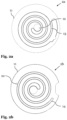
- FIGS. 2 a and 2 b show cross-sectional views of exemplary scroll plates of a compressor according to the invention.
- FIG. 3 shows a cross-sectional view of interleaved scroll plates, which form a scroll set and multiple compression chambers.
- FIGS. 4 a - 4 d show cross-sectional views of the interleaved scroll plates of FIG. 3 , wherein the FIGS. 4 a - 4 d show the transformation of an exemplary compression chamber through different time instances.
- FIG. 5 shows a cross-sectional view of another embodiment of a compressor according to the invention.
- FIG. 1 shows a cross-sectional view of an embodiment of a compressor 1 according to the invention.
- the compressor 1 comprises a suction port 7 for receiving a refrigerant and a discharge port 8 for discharging the refrigerant from the compressor 1 .
- the compressor design which is depicted in FIG. 1 , comprises a high pressure side and a low pressure side.
- the low pressure side comprises the suction port 7 and receives the refrigerant at a low temperature and a low pressure.
- the high pressure side comprises the discharge port 8 and receives the compressed refrigerant from the low pressure side and discharges said portion of the compressed refrigerant from the compressor 1 .
- the low pressure side and the high pressure side are connected to each other via a means for compressing.
- the compressor design which is depicted in FIG. 1 , is a scroll compressor.
- the means for compressing is formed by a scroll set 2 a , 2 b .
- the scroll set 2 a , 2 b comprises a first scroll plate 2 a , which is a stationary scroll plate in this example, and a second scroll plate 2 b , which is an orbiting scroll plate in this example.
- the stationary scroll plate 2 a and the orbiting scroll plate 2 b each comprise a spiral wrap and a base plate.
- the stationary scroll plate 2 a and the orbiting scroll plate 2 b are arranged in such a way that the sides of the scroll plates 2 a , 2 b , which comprise the spiral wraps, face each other. Further, the spiral wraps are interleaved. By interleaving the spiral wraps, the scroll plates 2 a , 2 b form one or more compression chambers, which are configured for compressing the refrigerant.
- the orbiting scroll plate 2 b is configured to change the volumes of the compression chambers by a motion relative to the stationary scroll plate 2 a .
- the orbiting scroll plate 2 b , the stationary scroll plate 2 a and their relative arrangement are configured to compress the refrigerant.
- the motion of the orbiting scroll plate 2 b is actuated by the motor 3 of the compressor 1 .
- the motor 3 is located in the low pressure side of the compressor 1 and is connected to the orbiting scroll plate 2 b by ease of a crank shaft 4 and a coupling.
- the compressor 1 comprises a lubricant reservoir 5 , which is used for lubricating the crankshaft 4 , the coupling, the motor 3 , and the scroll set 2 a , 2 b .
- the lubricant reservoir is also located at the low pressure side.
- the motion of the orbiting scroll plate 2 b may pump a portion of the refrigerant through the opening 10 to the motor 3 .
- the opening 10 is in fluid communication with a tube 9 and the extracted portion of the refrigerant may be piped to the motor via the tube 9 .
- the tube 9 ends below the motor 3 and the extracted portion of the refrigerant will diffuse in the low pressure side of the compressor 1 . Thereby, the extracted portion of the refrigerant will reach the motor 3 and the lubricant reservoir 5 and will cool these components.
- the extracted portion of the refrigerant will accept heat from said components. Thereby, the extracted portion of the refrigerant will heat up and will come back to the scroll set 2 a , 2 b .
- the extracted portion of the refrigerant may be received from the means for compressing, for example caused by a suction caused by the motion of the orbiting scroll plate 2 b.
- the refrigerant when it is received by the compressor 1 at its suction port 7 , will not evenly cool the components in the low pressure side of the compressor 1 . Because the refrigerant has a low temperature and the motor 3 has a high temperature during operation, the refrigerant may be in more contact with the upper part of the motor 3 , and in less contact with the lower part of the motor 3 . This raises a need for cooling the motor 3 more evenly, which is addressed by the motor cooling according to the invention.
- FIGS. 2 a , 2 b show cross-sectional views of exemplary scroll plates 2 a , 2 b of a compressor 1 according to an embodiment of the invention.
- the scroll plate 2 a depicted in FIG. 2 a is an example of a stationary scroll plate.
- the stationary scroll plate 2 a comprises a base plate 11 and a spiral wrap 13 , which is used to form a series of compression chambers upon interleaving with a corresponding spiral wrap of another scroll plate.
- the scroll plate 2 a comprises an outlet 12 .
- This outlet 12 may either correspond to the outlet of the means for compressing or may be in fluid connection with the outlet of the means for compressing.
- the scroll plate 2 b depicted in FIG. 2 b is an example of an orbiting scroll plate.
- the orbiting scroll plate 2 b comprises a base plate 11 and a spiral wrap 14 , which is used to form a series of compression chambers upon interleaving with a corresponding spiral wrap of another scroll plate, for example spiral wrap 13 of the stationary scroll plate 2 a .
- the orbiting scroll plate 2 b comprises an opening 10 , which is arranged at the base plate 11 .
- the opening 10 is arranged at the base plate 11 in such a way that the opening 10 will be in fluid communication with at least one of the compression chambers for at least a portion of time, when the orbiting scroll plate 2 b is interleaved with a corresponding stationary scroll plate 2 a .
- An example of a preferred location of the opening 10 on the base plate 11 is depicted in FIG. 3 .
- FIG. 3 shows a cross-sectional view of interleaved scroll plates, which form a scroll set and multiple compression chambers.
- the example depicted in FIG. 3 shows a stationary scroll plate 2 a as depicted in FIG. 2 a on top of an orbiting scroll plate 2 b as depicted in FIG. 2 b .
- the interleaved spiral wraps 13 , 14 engage each other at different locations and form compression chambers 15 in the spaces between the spiral wraps 13 , 14 .
- the location and the volume of the compression chambers 15 changes upon motion of the orbiting scroll plate 2 b , when the outermost compression chamber 15 will be transformed into an inner compression chamber.
- the compression chamber 15 is formed at a radially outer location of the spiral wraps 13 , 14 . Further, compression chamber 15 is closed because the radially outermost end of the spiral wrap 14 of the orbiting scroll plate 2 b engages the spiral wrap 14 of the stationary scroll plate 2 a . At this time instance, the opening 10 engages the edge of the compression chamber 15 , such that the opening 10 and the compression chamber 15 are in direct fluid communication. Upon further motion of the orbiting scroll plate 2 b , the compression chamber 15 will be moved along the course dictated by the involute curve of the spiral wraps 13 , 14 . Thereby, the volume of the compression chamber 15 will be reduced and the refrigerant inside the compression chamber 15 will be compressed.
- the refrigerant will only slightly be compressed, because a portion of the refrigerant will be pumped through the opening 10 in order to avoid an increase in pressure caused by a reduction in the volume of the compression chamber 15 . Thereby, a portion of the refrigerant will be extracted from the compression chamber 15 .
- FIGS. 4 a to 4 d show cross-sectional views of the interleaved scroll plates of FIG. 3 , wherein the FIGS. 4 a to 4 d show the transformation of an exemplary compression chamber through different time instances.
- Compression chamber 15 which was initially located at a radially outer location of the spiral wraps 13 , 14 , has now been transformed to an inner compression chamber with a reduced volume.
- the compression chamber is again moved further along the course dictated by the spiral wraps 13 , 14 and is transformed into a compression chamber the volume of which is even further reduced.
- FIG. 5 shows a cross-sectional view of another embodiment of a compressor according to the invention.
- the embodiment example depicted in FIG. 5 differs from the embodiment example depicted in FIG. 1 in that the opening 10 for extracting the portion of the refrigerant is located in the stationary scroll plate 2 a instead of the orbiting scroll plate 2 b as depicted in FIG. 1 .
- the person skilled in the art will appreciate that this difference may not change the operation of the cooling but only has an effect on the course of the tube 9 , which is used for supplying the extracted portion of the refrigerant to the motor 3 and/or the lubricant reservoir 5 .
- the stationary scroll plate 2 a and the orbiting scroll plate 2 b each comprise at least one opening 10 . In such a case, the operation of the cooling itself is not different to the examples shown, but the amount of extracted refrigerant and the number of tubes 9 may increase.
- the tube 9 is located at least partially outside of the casing 6 of the compressor 1 . Thereby, the tube 9 may pass the orbiting scroll plate 2 b without encountering the orbiting scroll plate 2 b . This allows to save space inside the casing 6 because the entire cross-section of the casing 6 is available for the motion of the orbiting scroll plate 2 b .
- the tube 9 is located entirely within the casing 6 of the compressor 1 when the opening 10 is in the stationary scroll plate 2 a . In this case, the tube 9 would pass the orbiting scroll plate 2 b within the casing 6 and reduce the space, which is available for the motion of the orbiting scroll plate 2 b.
- the embodiment example depicted in FIG. 5 differs from the embodiment example depicted in FIG. 1 in that the outlet of the tube 9 in the low pressure side of the compressor 1 is oriented horizontally.
- the person skilled in the art will appreciate that this is merely a design aspect and does not substantially affect the operation of the motor cooling. This is because the motion of the orbiting scroll 2 b pumps the extracted portion of the refrigerant through the tube 9 , such that the extracted portion of the refrigerant will be ejected from the tube 9 in the low pressure side at a pressure, which may be slightly higher than the pressure of the low pressure side.
Landscapes
- Engineering & Computer Science (AREA)
- Mechanical Engineering (AREA)
- General Engineering & Computer Science (AREA)
- Physics & Mathematics (AREA)
- Thermal Sciences (AREA)
- Rotary Pumps (AREA)
- Applications Or Details Of Rotary Compressors (AREA)
Applications Claiming Priority (3)
| Application Number | Priority Date | Filing Date | Title |
|---|---|---|---|
| EP19204296.8A EP3812589B1 (fr) | 2019-10-21 | 2019-10-21 | Refroidissement de compresseur avec fluide d'aspiration |
| EP19204296 | 2019-10-21 | ||
| EP19204296.8 | 2019-10-21 |
Publications (2)
| Publication Number | Publication Date |
|---|---|
| US20210116154A1 US20210116154A1 (en) | 2021-04-22 |
| US11906214B2 true US11906214B2 (en) | 2024-02-20 |
Family
ID=68296237
Family Applications (1)
| Application Number | Title | Priority Date | Filing Date |
|---|---|---|---|
| US17/063,248 Active 2041-06-04 US11906214B2 (en) | 2019-10-21 | 2020-10-05 | Compressor cooling |
Country Status (4)
| Country | Link |
|---|---|
| US (1) | US11906214B2 (fr) |
| EP (1) | EP3812589B1 (fr) |
| CN (1) | CN112761951B (fr) |
| ES (1) | ES2960489T3 (fr) |
Citations (16)
| Publication number | Priority date | Publication date | Assignee | Title |
|---|---|---|---|---|
| US3191403A (en) * | 1963-08-28 | 1965-06-29 | Gen Electric | Hermetically sealed multiple compressor unit |
| US4216661A (en) | 1977-12-09 | 1980-08-12 | Hitachi, Ltd. | Scroll compressor with means for end plate bias and cooled gas return to sealed compressor spaces |
| US4343599A (en) * | 1979-02-13 | 1982-08-10 | Hitachi, Ltd. | Scroll-type positive fluid displacement apparatus having lubricating oil circulating system |
| US4365941A (en) * | 1979-05-09 | 1982-12-28 | Hitachi, Ltd. | Scroll compressor provided with means for pressing an orbiting scroll member against a stationary scroll member and self-cooling means |
| JPH029979A (ja) | 1988-06-27 | 1990-01-12 | Mitsubishi Electric Corp | スクロール圧縮機 |
| US20010006604A1 (en) * | 1999-12-24 | 2001-07-05 | Choi Se Heon | Asymmetric scroll compressor |
| EP1260570A1 (fr) | 2001-05-17 | 2002-11-27 | Kabushiki Kaisha Toyota Jidoshokki | Procédés et dispositifs permettent d'empêcher la dégradation des propriétés d'isolant électrique dans des circuits de climatisation |
| EP1270947A2 (fr) | 2001-06-28 | 2003-01-02 | Kabushiki Kaisha Toyota Jidoshokki | Compresseur à spirales |
| US20030156961A1 (en) | 2002-02-19 | 2003-08-21 | Jiro Iizuka | Scroll compressor having a back pressure chamber in a rotation preventing mechanism |
| US20030161743A1 (en) | 2002-02-28 | 2003-08-28 | Kimberlin Robert R. | Fluid circulation path for motor pump |
| US20100129240A1 (en) | 2008-11-21 | 2010-05-27 | Hitachi Appliances, Inc. | Hermetically sealed scroll compressor |
| CN102297132A (zh) | 2010-06-24 | 2011-12-28 | Lg电子株式会社 | 涡旋压缩机 |
| CN102472528A (zh) | 2009-07-28 | 2012-05-23 | 三菱电机株式会社 | 热泵装置、喷射对应压缩机及喷射对应涡旋压缩机的制造方法 |
| EP2784266A2 (fr) | 2013-03-25 | 2014-10-01 | Kabushiki Kaisha Kobe Seiko Sho (Kobe Steel, Ltd.) | Appareil et système de génération de puissance |
| CN104421151A (zh) | 2013-08-21 | 2015-03-18 | 艾默生环境优化技术(苏州)有限公司 | 涡旋压缩机及其润滑剂供给方法以及制冷/热泵系统 |
| EP3043072A1 (fr) | 2015-01-12 | 2016-07-13 | LG Electronics Inc. | Compresseur à spirale et appareil de conditionnement d'air comprenant un compresseur à spirale |
-
2019
- 2019-10-21 ES ES19204296T patent/ES2960489T3/es active Active
- 2019-10-21 EP EP19204296.8A patent/EP3812589B1/fr active Active
-
2020
- 2020-10-05 US US17/063,248 patent/US11906214B2/en active Active
- 2020-10-19 CN CN202011117340.4A patent/CN112761951B/zh active Active
Patent Citations (17)
| Publication number | Priority date | Publication date | Assignee | Title |
|---|---|---|---|---|
| US3191403A (en) * | 1963-08-28 | 1965-06-29 | Gen Electric | Hermetically sealed multiple compressor unit |
| US4216661A (en) | 1977-12-09 | 1980-08-12 | Hitachi, Ltd. | Scroll compressor with means for end plate bias and cooled gas return to sealed compressor spaces |
| US4343599A (en) * | 1979-02-13 | 1982-08-10 | Hitachi, Ltd. | Scroll-type positive fluid displacement apparatus having lubricating oil circulating system |
| US4365941A (en) * | 1979-05-09 | 1982-12-28 | Hitachi, Ltd. | Scroll compressor provided with means for pressing an orbiting scroll member against a stationary scroll member and self-cooling means |
| JPH029979A (ja) | 1988-06-27 | 1990-01-12 | Mitsubishi Electric Corp | スクロール圧縮機 |
| US20010006604A1 (en) * | 1999-12-24 | 2001-07-05 | Choi Se Heon | Asymmetric scroll compressor |
| EP1260570A1 (fr) | 2001-05-17 | 2002-11-27 | Kabushiki Kaisha Toyota Jidoshokki | Procédés et dispositifs permettent d'empêcher la dégradation des propriétés d'isolant électrique dans des circuits de climatisation |
| CN1388346A (zh) | 2001-05-17 | 2003-01-01 | 株式会社丰田自动织机 | 一种防止空调回路中电绝缘性能降低的方法和装置 |
| EP1270947A2 (fr) | 2001-06-28 | 2003-01-02 | Kabushiki Kaisha Toyota Jidoshokki | Compresseur à spirales |
| US20030156961A1 (en) | 2002-02-19 | 2003-08-21 | Jiro Iizuka | Scroll compressor having a back pressure chamber in a rotation preventing mechanism |
| US20030161743A1 (en) | 2002-02-28 | 2003-08-28 | Kimberlin Robert R. | Fluid circulation path for motor pump |
| US20100129240A1 (en) | 2008-11-21 | 2010-05-27 | Hitachi Appliances, Inc. | Hermetically sealed scroll compressor |
| CN102472528A (zh) | 2009-07-28 | 2012-05-23 | 三菱电机株式会社 | 热泵装置、喷射对应压缩机及喷射对应涡旋压缩机的制造方法 |
| CN102297132A (zh) | 2010-06-24 | 2011-12-28 | Lg电子株式会社 | 涡旋压缩机 |
| EP2784266A2 (fr) | 2013-03-25 | 2014-10-01 | Kabushiki Kaisha Kobe Seiko Sho (Kobe Steel, Ltd.) | Appareil et système de génération de puissance |
| CN104421151A (zh) | 2013-08-21 | 2015-03-18 | 艾默生环境优化技术(苏州)有限公司 | 涡旋压缩机及其润滑剂供给方法以及制冷/热泵系统 |
| EP3043072A1 (fr) | 2015-01-12 | 2016-07-13 | LG Electronics Inc. | Compresseur à spirale et appareil de conditionnement d'air comprenant un compresseur à spirale |
Non-Patent Citations (2)
| Title |
|---|
| CA Search Report regarding European Patent Application No. 19204296.8, dated May 4, 2020. |
| Office Action with Search Report issued in corresponding Chinese Application No. 202011117340.4 dated May 5, 2023. |
Also Published As
| Publication number | Publication date |
|---|---|
| EP3812589B1 (fr) | 2023-07-19 |
| CN112761951A (zh) | 2021-05-07 |
| CN112761951B (zh) | 2023-11-14 |
| US20210116154A1 (en) | 2021-04-22 |
| EP3812589A1 (fr) | 2021-04-28 |
| ES2960489T3 (es) | 2024-03-05 |
Similar Documents
| Publication | Publication Date | Title |
|---|---|---|
| CN101542072B (zh) | 流体机械和冷冻循环装置 | |
| KR960001630B1 (ko) | 로우터리식 다단기체 압축기 | |
| EP2243958B1 (fr) | Compresseur et appareil de réfrigération en disposant | |
| JP2699724B2 (ja) | 2段気体圧縮機 | |
| CA2099989C (fr) | Compresseur de gaz a phases multiples avec robinet de derivation | |
| US8435014B2 (en) | Hermetically sealed scroll compressor | |
| EP1215450B1 (fr) | Dispositif de refrigeration a compression multi-etage | |
| CN109983230B (zh) | 具有注入功能的压缩机 | |
| JP2017044420A (ja) | 2段圧縮冷凍システム | |
| US11125232B2 (en) | Scroll compressor with cover member defining rear surface adjacent space | |
| US10982675B2 (en) | Rotary compressor with groove for supplying oil | |
| KR20060030521A (ko) | 스크롤형 유체기계 | |
| US11906214B2 (en) | Compressor cooling | |
| JP2699723B2 (ja) | 逆止弁装置を備えた2段圧縮冷凍装置 | |
| JP5269192B2 (ja) | 二段圧縮機及び冷凍空調装置 | |
| CN108072198B (zh) | 压缩机组件及其控制方法和制冷/制热系统 | |
| CN112567136B (zh) | 涡旋式压缩机 | |
| JP2008002430A (ja) | スクロール圧縮機 | |
| KR20190074359A (ko) | 다중 압축식 수소 압축 시스템 | |
| US20220146171A1 (en) | Compressor and refrigeration cycle device having the same | |
| JP4631551B2 (ja) | スクロール圧縮機 | |
| JP2009052462A (ja) | スクロール圧縮機 | |
| JP5191405B2 (ja) | 膨張機一体型圧縮機および冷凍サイクル装置 | |
| JP2009052463A (ja) | スクロール圧縮機 | |
| JP2022148052A (ja) | 密閉型ロータリ圧縮機及びこれを用いた冷蔵庫 |
Legal Events
| Date | Code | Title | Description |
|---|---|---|---|
| FEPP | Fee payment procedure |
Free format text: ENTITY STATUS SET TO UNDISCOUNTED (ORIGINAL EVENT CODE: BIG.); ENTITY STATUS OF PATENT OWNER: LARGE ENTITY |
|
| STPP | Information on status: patent application and granting procedure in general |
Free format text: APPLICATION DISPATCHED FROM PREEXAM, NOT YET DOCKETED |
|
| AS | Assignment |
Owner name: EMERSON CLIMATE TECHNOLOGIES GMBH, GERMANY Free format text: ASSIGNMENT OF ASSIGNORS INTEREST;ASSIGNORS:SU, XIAOGENG;NOHALES HERRAIZ, JESUS ANGEL;DELLWEG, LINUS;AND OTHERS;SIGNING DATES FROM 20201113 TO 20210614;REEL/FRAME:058079/0911 |
|
| STPP | Information on status: patent application and granting procedure in general |
Free format text: DOCKETED NEW CASE - READY FOR EXAMINATION |
|
| STPP | Information on status: patent application and granting procedure in general |
Free format text: NON FINAL ACTION MAILED |
|
| STPP | Information on status: patent application and granting procedure in general |
Free format text: DOCKETED NEW CASE - READY FOR EXAMINATION |
|
| AS | Assignment |
Owner name: COPELAND EUROPE GMBH, GERMANY Free format text: CHANGE OF NAME;ASSIGNOR:EMERSON CLIMATE TECHNOLOGIES GMBH;REEL/FRAME:065192/0181 Effective date: 20230712 |
|
| STPP | Information on status: patent application and granting procedure in general |
Free format text: NOTICE OF ALLOWANCE MAILED -- APPLICATION RECEIVED IN OFFICE OF PUBLICATIONS |
|
| STPP | Information on status: patent application and granting procedure in general |
Free format text: PUBLICATIONS -- ISSUE FEE PAYMENT RECEIVED |
|
| STPP | Information on status: patent application and granting procedure in general |
Free format text: PUBLICATIONS -- ISSUE FEE PAYMENT VERIFIED |
|
| STCF | Information on status: patent grant |
Free format text: PATENTED CASE |