US11897155B2 - Razor - Google Patents
Razor Download PDFInfo
- Publication number
- US11897155B2 US11897155B2 US17/773,300 US202017773300A US11897155B2 US 11897155 B2 US11897155 B2 US 11897155B2 US 202017773300 A US202017773300 A US 202017773300A US 11897155 B2 US11897155 B2 US 11897155B2
- Authority
- US
- United States
- Prior art keywords
- razor
- head
- cut
- holding part
- folding
- Prior art date
- Legal status (The legal status is an assumption and is not a legal conclusion. Google has not performed a legal analysis and makes no representation as to the accuracy of the status listed.)
- Active
Links
- 229910052751 metal Inorganic materials 0.000 claims abstract description 21
- 239000002184 metal Substances 0.000 claims abstract description 21
- 239000000853 adhesive Substances 0.000 claims description 35
- 230000001070 adhesive effect Effects 0.000 claims description 35
- 210000004209 hair Anatomy 0.000 claims description 21
- 238000003780 insertion Methods 0.000 description 76
- 230000037431 insertion Effects 0.000 description 76
- 238000012986 modification Methods 0.000 description 60
- 230000004048 modification Effects 0.000 description 60
- 210000001015 abdomen Anatomy 0.000 description 29
- 238000004519 manufacturing process Methods 0.000 description 28
- 239000000463 material Substances 0.000 description 23
- 210000003811 finger Anatomy 0.000 description 22
- 230000013011 mating Effects 0.000 description 18
- 238000004064 recycling Methods 0.000 description 16
- 230000000717 retained effect Effects 0.000 description 14
- 238000005452 bending Methods 0.000 description 12
- 230000009467 reduction Effects 0.000 description 11
- 239000011347 resin Substances 0.000 description 11
- 229920005989 resin Polymers 0.000 description 11
- 238000000034 method Methods 0.000 description 9
- 230000004044 response Effects 0.000 description 8
- XEEYBQQBJWHFJM-UHFFFAOYSA-N Iron Chemical compound [Fe] XEEYBQQBJWHFJM-UHFFFAOYSA-N 0.000 description 6
- 238000005520 cutting process Methods 0.000 description 5
- 238000000926 separation method Methods 0.000 description 5
- 238000013459 approach Methods 0.000 description 4
- 238000003776 cleavage reaction Methods 0.000 description 4
- 239000007769 metal material Substances 0.000 description 4
- 230000007017 scission Effects 0.000 description 4
- 238000013461 design Methods 0.000 description 3
- 229910052742 iron Inorganic materials 0.000 description 3
- 230000008569 process Effects 0.000 description 3
- 239000002699 waste material Substances 0.000 description 3
- 229910000599 Cr alloy Inorganic materials 0.000 description 2
- PXHVJJICTQNCMI-UHFFFAOYSA-N Nickel Chemical compound [Ni] PXHVJJICTQNCMI-UHFFFAOYSA-N 0.000 description 2
- 230000008859 change Effects 0.000 description 2
- 238000011161 development Methods 0.000 description 2
- 239000000203 mixture Substances 0.000 description 2
- 239000010935 stainless steel Substances 0.000 description 2
- 229910001220 stainless steel Inorganic materials 0.000 description 2
- 210000003813 thumb Anatomy 0.000 description 2
- XLYOFNOQVPJJNP-UHFFFAOYSA-N water Substances O XLYOFNOQVPJJNP-UHFFFAOYSA-N 0.000 description 2
- VYZAMTAEIAYCRO-UHFFFAOYSA-N Chromium Chemical compound [Cr] VYZAMTAEIAYCRO-UHFFFAOYSA-N 0.000 description 1
- 229910000640 Fe alloy Inorganic materials 0.000 description 1
- 229910000990 Ni alloy Inorganic materials 0.000 description 1
- ATJFFYVFTNAWJD-UHFFFAOYSA-N Tin Chemical compound [Sn] ATJFFYVFTNAWJD-UHFFFAOYSA-N 0.000 description 1
- 239000011651 chromium Substances 0.000 description 1
- 239000011248 coating agent Substances 0.000 description 1
- 238000000576 coating method Methods 0.000 description 1
- 230000000694 effects Effects 0.000 description 1
- 230000007613 environmental effect Effects 0.000 description 1
- 239000000123 paper Substances 0.000 description 1
- 230000001737 promoting effect Effects 0.000 description 1
- 238000003860 storage Methods 0.000 description 1
- 239000005028 tinplate Substances 0.000 description 1
- 238000013519 translation Methods 0.000 description 1
Images


Classifications
-
- B—PERFORMING OPERATIONS; TRANSPORTING
- B26—HAND CUTTING TOOLS; CUTTING; SEVERING
- B26B—HAND-HELD CUTTING TOOLS NOT OTHERWISE PROVIDED FOR
- B26B21/00—Razors of the open or knife type; Safety razors or other shaving implements of the planing type; Hair-trimming devices involving a razor-blade; Equipment therefor
- B26B21/40—Details or accessories
- B26B21/52—Handles, e.g. tiltable, flexible
- B26B21/522—Ergonomic details, e.g. shape, ribs or rubber parts
-
- B—PERFORMING OPERATIONS; TRANSPORTING
- B26—HAND CUTTING TOOLS; CUTTING; SEVERING
- B26B—HAND-HELD CUTTING TOOLS NOT OTHERWISE PROVIDED FOR
- B26B21/00—Razors of the open or knife type; Safety razors or other shaving implements of the planing type; Hair-trimming devices involving a razor-blade; Equipment therefor
- B26B21/40—Details or accessories
- B26B21/4012—Housing details, e.g. for cartridges
-
- B—PERFORMING OPERATIONS; TRANSPORTING
- B26—HAND CUTTING TOOLS; CUTTING; SEVERING
- B26B—HAND-HELD CUTTING TOOLS NOT OTHERWISE PROVIDED FOR
- B26B21/00—Razors of the open or knife type; Safety razors or other shaving implements of the planing type; Hair-trimming devices involving a razor-blade; Equipment therefor
- B26B21/40—Details or accessories
- B26B21/52—Handles, e.g. tiltable, flexible
- B26B21/523—Extendible or foldable handles; Extensions
-
- B—PERFORMING OPERATIONS; TRANSPORTING
- B26—HAND CUTTING TOOLS; CUTTING; SEVERING
- B26B—HAND-HELD CUTTING TOOLS NOT OTHERWISE PROVIDED FOR
- B26B21/00—Razors of the open or knife type; Safety razors or other shaving implements of the planing type; Hair-trimming devices involving a razor-blade; Equipment therefor
- B26B21/02—Razors of the open or knife type; Safety razors or other shaving implements of the planing type; Hair-trimming devices involving a razor-blade; Equipment therefor involving unchangeable blades
- B26B21/06—Safety razors with fixed blade, e.g. with moulded-in blade
-
- B—PERFORMING OPERATIONS; TRANSPORTING
- B26—HAND CUTTING TOOLS; CUTTING; SEVERING
- B26B—HAND-HELD CUTTING TOOLS NOT OTHERWISE PROVIDED FOR
- B26B21/00—Razors of the open or knife type; Safety razors or other shaving implements of the planing type; Hair-trimming devices involving a razor-blade; Equipment therefor
- B26B21/08—Razors of the open or knife type; Safety razors or other shaving implements of the planing type; Hair-trimming devices involving a razor-blade; Equipment therefor involving changeable blades
- B26B21/14—Safety razors with one or more blades arranged transversely to the handle
-
- B—PERFORMING OPERATIONS; TRANSPORTING
- B26—HAND CUTTING TOOLS; CUTTING; SEVERING
- B26B—HAND-HELD CUTTING TOOLS NOT OTHERWISE PROVIDED FOR
- B26B21/00—Razors of the open or knife type; Safety razors or other shaving implements of the planing type; Hair-trimming devices involving a razor-blade; Equipment therefor
- B26B21/40—Details or accessories
- B26B21/4006—Blades or blade units with discontinuous cutting edges, e.g. wire-wrapped, notches
-
- B—PERFORMING OPERATIONS; TRANSPORTING
- B26—HAND CUTTING TOOLS; CUTTING; SEVERING
- B26B—HAND-HELD CUTTING TOOLS NOT OTHERWISE PROVIDED FOR
- B26B21/00—Razors of the open or knife type; Safety razors or other shaving implements of the planing type; Hair-trimming devices involving a razor-blade; Equipment therefor
- B26B21/40—Details or accessories
- B26B21/52—Handles, e.g. tiltable, flexible
-
- B—PERFORMING OPERATIONS; TRANSPORTING
- B26—HAND CUTTING TOOLS; CUTTING; SEVERING
- B26B—HAND-HELD CUTTING TOOLS NOT OTHERWISE PROVIDED FOR
- B26B21/00—Razors of the open or knife type; Safety razors or other shaving implements of the planing type; Hair-trimming devices involving a razor-blade; Equipment therefor
- B26B21/54—Razor-blades
- B26B21/58—Razor-blades characterised by the material
Definitions
- One aspect of the present invention relates to a ready-to-assemble razor.
- a conventional razor is generally composed of a body with a head and a handle integral with each other, and a razor head with a metal blade housed in a resin case.
- the body is formed of resin or metal and requires a large housing capacity, causing the need of ensuring housing space for storage or causing inconvenience of carriage.
- the 3R has been proposed that is a collective term of 3Rs including Reduce intended to use things with case and reduce waste, Reuse intended to use available things repeatedly, and Recycle intended to use waste again as resources.
- conventional razors are formed of resin and metal as described above, replacement thereof with easy to recycle materials is also required.
- a razor including a body formed of paper as a replacement for resin is available as an environmentally responsible razor for contributing to a recycling-oriented society.
- the 17 goals of the Sustainable Development Goals (SDGs) adopted by the United Nations summit include those to ensure sustainable consumption and production patterns requiring significant reduction in waste production, etc. Under these circumstances, in the field of razors, there is also demand for promoting development of environmentally-friendly razors satisfying the 3R.
- a razor with a body formed of an easily-recyclable material such as paper is promising as an environmentally-friendly technique satisfying the 3R.
- Such razors formed of paper for example, are disclosed in Patent Documents 1 to 12, for example.
- Patent Documents 1 to 12 include bodies formed of paper, for example, to form environmentally-responsible configurations, they have the following problems.
- Patent Documents 1 to 7 each disclose a razor with a body having a substantially rectangular sheet-like shape in a state before assembly. In these razors, the sheet forming the body before assembly has a substantially rectangular shape to make the razors easily formable.
- limitation is imposed on a degree of freedom of design and the size of the body becomes larger than is necessary. Such a configuration with the body larger than is necessary increases the amount of use of a material such as paper to form the body and is far from environmentally friendly.
- Patent Documents 1 to 12 mentioned above each have a configuration assembled by causing a user to fold the sheet-like body several times. This requires many steps for the assembly and involves a complicated method of the assembly. Thus, the user is required to perform burdensome operation for making the razor ready to use, failing to provide an easy to assemble configuration.
- One of objects of using a razor with a body formed of paper is to recycle materials.
- the razor may be required to be separated according to materials such as paper, resin, metal, etc.
- materials such as paper, resin, metal, etc.
- the conventional razor even if the body is formed of paper entirely, consideration is not given to detachment of a razor head from the body and the body and the razor head are firmly adhered to each other. This makes it difficult to separate the body and the razor head from each other and trying to separate the body and the razor head may break the razor head.
- use of a resin material and a metal material forming the razor head results in inclusion of the resin material and the metal material in the razor head to cause a mixture of a plurality of materials.
- a surface of the rectangular piece 8 to which the razor blade 7 is fixedly attached forms an angle together with the outer surface 33 of a loose arc-like shape forming a head.
- the blade or a razor head may come off an end of the head formed of paper or the body may be broken partially with the external force.
- Such a configuration is common to the patent documents mentioned above other than Patent Document 12, so that it becomes a problem common to conventional razors including bodies formed of paper.
- the present invention is intended to provide a razor that can solve the above-described problem.
- the present invention provides a razor having a configuration as follows.
- signs, etc. in the drawings will be added in parentheses.
- each constituting element of the present invention should not be limited to such a specific configuration but should be interpreted widely to cover a range graspable by a person skilled in the art.
- One means of the present invention is intended for a razor that is assembled by folding, the razor comprising:
- a holding part that is held by a user
- a head supporting part that is formed integrally with the holding part
- a razor head that is provided on the head supporting part
- the entire of the holding part and the head supporting part is formed of paper
- the entire of the razor head is formed of metal, and the razor head includes a blade body and a frame body housing the blade body,
- the head supporting part includes a both end supporting portion that supports at least both ends in a width direction of the razor head, and
- the frame body is formed at least at a part of a periphery portion from a side facing the head supporting part, and includes a cut-out portion through which body hairs cut by the blade body can pass and that has a force point portion for removing the razor head from the head supporting part.
- the razor head formed of metal can be removed easily from the holding part and the head supporting part formed of paper. This facilitates sorting for a user to facilitate recycling.
- the cut-out portion having both the function of facilitating removal and the function of causing cut body hairs to pass for preventing these body hairs from remaining in the razor head, it becomes possible to provide a razor that facilitates recycling through sorted disposal in a relatively simple configuration, and at the same time, can be used cleanly and comfortably.
- the head supporting part is not positioned at least at a part of a position facing the cut-out portion.
- the razor having the above-described configuration causes a user to touch the cut-out portion easily in removing the razor head from the head supporting part, thereby facilitating sorted disposal further. Additionally, as cut body hairs are caused to pass through the cut-out portion easily, it becomes possible to reduce the likelihood further that body hairs will remain in the razor head. As a result, the razor can be used more cleanly and more comfortably.
- the razor head includes an opening portion through which body hairs cut by the blade body can pass, and the opening portion is provided on a surface facing the head supporting part and a position on the surface not faced by the head supporting part.
- the razor having the above-described configuration causes cut body hairs to pass further through the opening portion. This makes it possible to reduce the likelihood further that body hairs will remain in the razor head. As a result, the razor can be used more cleanly and more comfortably.
- the razor head is adhered to the head supporting part on a side closer to an edge portion on an opposite side of an edge portion having the cut-out portion.
- the razor having the above-described configuration achieves a configuration where, when a user applies force to the cut-out portion with the intention of removing the razor head from the head supporting part, the force acting for removing the razor head from the head supporting part is transmitted easily. This makes it possible to facilitate sorted disposal further.
- the frame body includes a front case having the opening portion from which
- the front case has a box shape that is open on a side facing the rear case
- the rear case has a box shape that is open on a side facing the front case
- the front case is arranged to cover the rear case
- a distance between an edge portion of the front case having the cut-out portion and an edge portion of the rear case facing the edge portion of the front case is not smaller than 0.5 mm and not larger than 3 mm.
- the razor having the above-described configuration causes a user to touch the cut-out portion more easily in removing the razor head from the head supporting part, thereby facilitating sorted disposal further.
- the razor head is directly adhered to the both end supporting portion in an adhesive region other than an adhesion prohibited region that is provided in a given range from the periphery portion of the frame body.
- the razor head can be configured to be removed easily from the head supporting part.
- the razor having the above-described configuration, even if the adhesive region is relatively small, it is still possible to adhere the razor head to the head supporting part stably to achieve a configuration that can be used comfortably while being sorted easily.
- the head supporting part further includes a triangular triangle part that is formed between the both end supporting portion and the holding part,
- the head supporting part and the holding part are planar
- the holding part is formed to extend in a longitudinal direction crossing the width direction, is symmetrical relative to a center line extending in the longitudinal direction, is connected to the triangle part of the head supporting part, branches along a connection part with the triangle part to be tapered, includes a narrow portion formed to be narrow in the width direction in a vicinity of a vertex of the triangle part crossing the center line, is formed to be expanded in the width direction from the narrow portion toward an end on the opposite side of the connection part, includes the end that is curved, has a center fold along the center line from the vertex to the end, and has a connection fold along the connection part, the razor head includes, in each vicinity of both ends in the width direction, a rectangular and planar rectangular-planar part, and the rectangular-planar part is adhered to a front surface of the both end supporting portion, a folding part is formed to project outward along the edge portion of the holding part and to be foldable to the side of the center line, the folding part has a width smaller than a width of the holding part, in assembly,
- One means of the present invention is intended for a razor that is assembled by folding, the razor comprising: a holding part that is held by a user; a head supporting part that is formed integrally with the holding part; and a razor head that is provided on the head supporting part, wherein
- the entire of the holding part and the head supporting part is formed of paper
- the entire of the razor head is formed of metal
- the head supporting part and the holding part are planar
- the head supporting part includes a both end supporting portion that supports at least both ends in a width direction of the razor head, and a triangular triangle part that is formed between the both end supporting portion and the holding part,
- the holding part is formed to extend in a longitudinal direction crossing the width direction, is symmetrical relative to a center line extending in the longitudinal direction, is connected to the triangle part of the head supporting part, branches along a connection part with the triangle part to be tapered, includes a narrow portion formed to be narrow in the width direction in a vicinity of a vertex of the triangle part crossing the center line, is formed to be expanded in the width direction from the narrow portion toward an end on the opposite side of the connection part, includes the end that is curved, has a center fold along the center line from the vertex to the end, and has a connection fold along the connection part, the razor head includes, in each vicinity of both ends in the width direction, a rectangular and substantially planar rectangular-planar part, and the rectangular-planar part is adhered to a front surface of the both end supporting portion, a folding part is formed to project outward along the edge portion of the holding part and to be foldable to the side of the center line, the folding part has a width smaller than a width of the holding part, in assembly
- the outer shape of the planar razor is not formed into a rectangular but can be formed into a shape with rounded corners. This achieves reduction in the amount of use of paper. Avoiding a rectangular shape as the outer shape of the razor increases a degree of freedom of design to achieve the compact body. Furthermore, while an index finger and a thumb of a user are to be located in the vicinity of the narrow portion when the user uses the razor, the presence of the narrow portion can form a configuration that prevents the finger of the user from coming off the razor downward.
- connection fold is formed along the connection part
- a user makes folding along the connection fold and the center fold in assembly, folding the holding part along the center fold naturally achieves folding along the connection fold further continuous with the center fold.
- folding the holding part along the connection fold naturally achieves folding along the center fold further continuous with the connection fold.
- this allows the user to assemble the razor through a single touch, for example, thereby reducing the number of steps required for assembling the razor to facilitate assembly of the razor.
- This achieves a configuration that eliminates the burdensome operation for the user to make the razor ready to use.
- the head supporting part In folding along the connection fold, the head supporting part can be bent smoothly toward the side of the belly part.
- the end and its vicinity are not formed into a linear shape but can be rounded in a state after assembly.
- the razor head includes, in the vicinities of both ends in the width direction, the rectangular and substantially planar rectangular-planar parts, and these two rectangular-planar parts are adhered to a front surface of the both end supporting portion, it is possible to adhere the razor head and the both end supporting portion to each other with appropriate strength while consideration is given to ease of stripping. This makes it possible to separate the body and the razor head from each other easily without damaging the razor head. This reduces the likelihood that the blade of the razor will be exposed during the separation, making it possible to provide a razor giving consideration to safety.
- the razor head and the surface of the both end supporting portion close to the back part substantially parallel to each other. This allows a user to press the blade of the razor head against a skin at an angle at which the blade comes into surface contact with the skin in operating the holding part. Furthermore, if external force is applied to the blade, unlike in the conventional configuration where the external force is received in a direction substantially orthogonal to the surface of the both end supporting portion closer to the back part, the external force can be received along this surface. This can reduce the likelihood that the razor head will come off the head supporting part or the body will be damaged partially due to the external force.
- the folding part is formed to project outward along the edge portion of the holding part and to be foldable to the side of the center line, and the folding part has a width smaller than a width of the holding part, as a result of the provision of the folding part, the belly part of the holding part is given a rounded shape to make the shape of the holding part easy to hold for a user. Furthermore, the belly part to which a finger of a user is likely to abut on is not given a sharp portion, making it possible to provide a razor giving consideration to safety.
- the above-described razor further comprises:
- the head fixing part provided on the opposite side of the holding part relative to the head supporting part, and folded to be fitted to the holding part or the head supporting part.
- the rigidity of the holding part or the head supporting part can be increased. This makes it possible to stabilize the position of the razor head.
- the razor can be used with an operational feeling similar to that provided by a different high-rigidity razor using resin or metal, for example, for forming a part corresponding to the holding part or the head supporting part.
- the holding part is assembled in such a manner that a section taken at a plane intersecting the longitudinal direction is fixed in a polygonal shape.
- the razor having the above-described configuration suppresses change in the shape of the holding part occurring when the holding part is held, making it possible to stabilize the shape of the holding part. This makes the holding part easy to grip. Furthermore, while the razor is formed of paper, the razor can be used with an operational feeling similar to that provided by a different high-rigidity razor using resin or metal, for example, for forming a part corresponding to the holding part or the head supporting part.
- the holding part includes a long hole part extending in the longitudinal direction in a state before assembly.
- the razor having the above-described configuration, when a side of a finger of a user is placed on the long hole part, friction is generated between the edge of the long hole part and the finger of the user, thereby forming a part on which the user is to hook the finger. This allows the razor to be held more easily while suppressing slippage.
- a part of the razor head closer to the holding part projects from the both end supporting portion toward the holding part
- the razor head is removable from the head supporting part after use.
- a part of the razor head closer to the holding part projects from the both end supporting portion toward the holding part and the razor head is removable from the head supporting part after use.
- a tapered part of the holding part branching along the connection fold goes farther from the part closer to the holding to allow the part of the razor head closer to the holding part to be exposed.
- the razor head is entirely formed of metal and the holding part and the head supporting part are integrally formed of paper
- the razor head is entirely formed of metal and the holding part and the head supporting part are integrally formed of paper
- the razor head can be located near the vertex of the triangle part.
- the amount of deformation is reduced in the vicinity of the vertex of the triangle part.
- the head supporting part and the holding part are configured to be elastically deformed in such a manner that the razor head is biased toward a skin of a user when the user makes the razor head touch the skin.
- the razor having the above-described configuration provides appropriate elasticity to the head supporting part and the holding part formed of paper to prevent application of excessive pressure to the skin.
- the holding part includes: an insertion part formed on one side relative to the center line and deformed by being pressed; and
- the insertion part is inserted into and fitted to the insertion hole part to fix the holding part in a state of being folded along the center fold.
- the fit between the insertion part and the insertion hole part makes it possible to reduce the likelihood that the holding part will unintentionally stretch on the belly side in response to the elasticity of paper around the center fold, so that the holding part can be retained in a shape easy to hold for a user. It is also possible to reduce the likelihood that the bending of the head supporting part will unintentionally return toward the back part to allow the head supporting part to be retained in a state bent appropriately relative to the holding part.
- the holding part in a state after assembly, includes a cut portion formed in such a manner as to extend from the back part toward the belly part, and the holding part is fixed in a state of being folded along the center fold by folding the cut portion.
- the razor in a state after assembly, it is possible to reduce the likelihood that the holding part will unintentionally stretch on the belly side in response to the elasticity of paper around the center fold, so that the holding part can be retained in a shape easy to hold for a user. It is also possible to reduce the likelihood that the bending of the head supporting part will unintentionally return toward the back part to allow the head supporting part to be retained in a state bent appropriately relative to the holding part.
- the above-described razor further comprises:
- the projection is inserted into and fitted to the cut-out portion to fix the holding part in a state of being folded along the center fold.
- the razor in a state after assembly, it is possible to reduce the likelihood that the holding part will unintentionally stretch on the belly side in response to the elasticity of paper around the center fold, so that the holding part can be retained in a shape easy to hold for a user. It is also possible to reduce the likelihood that the bending of the head supporting part will unintentionally return toward the back part to allow the head supporting part to be retained in a state bent appropriately relative to the holding part.
- FIG. 1 is a plan view from a front side showing a razor being manufactured according to an embodiment.
- FIG. 2 is a plan view from a front side showing the razor at completion of manufacture according to the embodiment.
- FIG. 3 is an enlarged view showing an insertion part, an insertion hole part, and their vicinities of the razor shown in FIG. 1 .
- FIG. 4 is a perspective view showing the razor in a state after assembly according to the embodiment.
- FIG. 5 is a plan view from a width direction showing the razor in a state after assembly according to the embodiment.
- FIG. 6 is a plan view from a front side showing the razor in a state after assembly according to the embodiment.
- FIG. 7 is a plan view from a back side showing the razor in a state after assembly according to the embodiment.
- FIG. 8 is a plan view from above showing the razor in a state after assembly according to the embodiment.
- FIG. 9 is a plan view from below showing the razor in a state after assembly according to the embodiment.
- FIG. 10 is a plan view from a front side showing a razor head according to the embodiment.
- FIG. 11 is a plan view from a back side showing the razor head according to the embodiment.
- FIG. 12 is a plan view from a front side showing a razor at completion of manufacture according to a first modification of the embodiment.
- FIG. 13 is a plan view from a front side showing a razor at completion of manufacture according to a second modification of the embodiment.
- FIG. 14 is an enlarged view showing a cut portion and its vicinity of the razor shown in FIG. 13 .
- FIG. 15 is an enlarged view from a back side showing the cut portion and its vicinity in a state where a small piece part is folded to the right according to the second modification of the embodiment.
- FIG. 16 is a plan view from a front side showing a razor at completion of manufacture according to a third modification of the embodiment.
- FIG. 17 is an enlarged view from a belly side showing a right projection and its vicinity in a state where the right projection is fitted to a cut-out portion according to the third modification of the embodiment.
- FIG. 18 is a plan view from a front side showing a razor according to a fourth modification of the embodiment.
- FIG. 19 is a plan view from a front side showing the razor in a state where a razor head is detached according to the fourth modification of the embodiment.
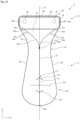
- FIG. 20 is a plan view from a front side showing the razor in a state after assembly according to the fourth modification of the embodiment.
- FIG. 21 is a plan view from the width direction showing the razor in a state after assembly according to the fourth modification of the embodiment.
- FIG. 22 is a plan view from a back side showing the razor in a state after assembly according to the fourth modification of the embodiment.
- FIG. 23 is a plan view from below showing the razor in a state after assembly according to the fourth modification of the embodiment.
- FIG. 24 is a perspective view showing the razor head according to the fourth modification of the embodiment.
- FIG. 25 is a plan view from a front side showing a razor according to a fifth modification of the embodiment.
- FIG. 26 is a plan view from a front side showing the razor in a state after assembly according to the fifth modification of the embodiment.
- FIG. 27 is a plan view from a back side showing the razor in a state after assembly according to the fifth modification of the embodiment.
- FIG. 28 is a plan view from a front side showing a razor according to a sixth modification of the embodiment.
- One of features of a razor according to one embodiment of the present invention is that, in order to contribute to fulfilment of the goals of the SDGs, the razor has an environmentally-friendly configuration satisfying the 3R.
- FIG. 1 is a plan view from a front side showing a razor being manufactured according to an embodiment.
- FIG. 2 is a plan view from a front side showing the razor at completion of manufacture according to the embodiment.
- FIG. 3 is an enlarged view showing an insertion part, an insertion hole part, and their vicinities of the razor shown in FIG. 1 .
- FIG. 4 is a perspective view showing the razor in a state after assembly according to the embodiment.
- FIG. 5 is a plan view from a width direction showing the razor in a state after assembly according to the embodiment.
- FIG. 6 is a plan view from a front side showing the razor in a state after assembly according to the embodiment.
- FIG. 7 is a plan view from a back side showing the razor in a state after assembly according to the embodiment.
- FIG. 8 is a plan view from above showing the razor in a state after assembly according to the embodiment.
- FIG. 9 is a plan view from below showing the razor in a state after assembly according to the embodiment.
- FIG. 10 is a plan view from a front side showing a razor head according to the embodiment.
- FIG. 11 is a plan view from a back side showing the razor head according to the embodiment.
- An x axis, a y axis, and a z axis are shown in each of the drawings.
- An axis pointed toward a direction vertical to a sheet of paper on a plane forming the razor is defined as the “z axis.”
- An axis vertical to the z axis is defined as the “y axis.”
- An axis vertical to both the y axis and the z axis is defined as the “x axis.”
- the x axis, the y axis, and the z axis form right-handed 3 D orthogonal coordinates.
- a direction of an arrow of the z axis may be called a z axis+side, and a direction opposite the arrow may be called a z axis ⁇ side.
- the z axis+side and the z axis ⁇ side may be called a “front side” and a “back side” respectively.
- An x axis+side and an x axis ⁇ side may be called a “right side” and a “left side” respectively.
- a y axis+side and a y axis ⁇ side may be called an “upper side” and a “lower side” respectively.
- the upper side and the lower side may be tilted mainly toward the z axis with respect to the y axis.
- the y axis direction may be called a longitudinal direction.
- the x axis direction may be called a width direction.
- the z axis direction may be called a thickness direction.
- a razor 1 of the embodiment has a configuration including a razor head 61 and a body 40 .
- the body 40 has a configuration including a holding part 11 , a folding part 14 a , a folding part 14 b , and a head supporting part 31 .
- the body 40 of a planar shape and the razor head 61 are manufactured separately, for example.
- the razor 1 shown in FIG. 1 is manufactured by connecting the body 40 and the razor head 61 manufactured separately. Then, the folding parts 14 a and 14 b of the body 40 are each folded to the back side to manufacture the razor 1 as a finished good shown in FIG. 2 .
- the razor 1 shown in FIG. 1 is the razor 1 in a state being manufactured
- the razor 1 shown in FIG. 2 is the razor 1 in a state at completion of manufacture at a factory.
- the razor 1 shown in FIG. 2 at completion of manufacture is assembled to become the razor 1 having a stereoscopic shape shown in FIGS. 4 to 9 .
- the body 40 is integrally formed of paper.
- the body is formed of a paper material having water resistance or a paper material having a surface with water-resistant coating.
- the body 40 is formed into a planar shape by cutting paper along the contour of the body 40 .
- the body 40 has a thickness of about 1 mm, for example.
- the body 40 extends parallel to the xy plane and has an outer shape bilaterally symmetrical with respect to a center line CL parallel to the y axis.
- a right end, a left end, an upper end, and a lower end of the planar body 40 are defined as a right end 40 a , a left end 40 b , an upper end 40 c , and a lower end 40 d respectively.
- an entire width W 1 from the right end 40 a to the left end 40 b is about 57 mm.
- An entire length L 1 from the upper end 40 c to the lower end 40 d is about 89 mm.
- the body 40 is provided with a center fold 41 , a connection fold 42 a , a connection fold 42 b , an inversion fold 43 a , and an inversion fold 43 to facilitate folding during manufacture and assembly of the razor 1 .
- the folds are creases or perforations formed on paper, for example.
- the center fold 41 is formed to extend upward along the center line CL from the lower end 40 d of the body 40 .
- the center fold 41 branches upward from a vertex 17 located on the center line CL into the connection fold 42 a and the connection fold 42 b.
- connection fold 42 b is formed to extend upward and leftward from the vertex 17 to the left end of the body 40 .
- the connection fold 42 b has a configuration including a curved fold 42 bc and a linear fold 42 bs .
- the curved fold 42 bc is connected to the vertex 17 and is curved in such a manner as to be convex rightward.
- the linear fold 42 bs is connected to the curved fold 42 bc on the left side of the curved fold 42 bc and extends substantially linearly to the left end of the body 40 .
- connection fold 42 a is formed to extend upward and rightward from the vertex 17 to the right end of the body 40 in such a manner as to be bilaterally symmetrical to the connection fold 42 b with respect to the center line CL.
- the connection fold 42 a has a configuration including a curved fold 42 ac and a linear fold 42 as .
- the curved fold 42 ac has a shape bilaterally symmetrical to the curved fold 42 bc with respect to the center line CL.
- the linear fold 42 as has a shape bilaterally symmetrical to the linear fold 42 bs with respect to the center line CL.
- connection folds 42 a and 42 b form a boundary between the holding part 11 and the head supporting part 31 .
- a part on the lower side of each of the connection folds 42 a and 42 b is the holding part 11
- a part on the upper side of each of the connection folds 42 a and 42 b is the head supporting part 31 .
- a part along the connection fold 42 a and a part along the connection fold 42 b may be called a connection part 46 a and a connection part 46 b respectively.
- the connection parts 46 a and 46 b connect the holding part 11 and the head supporting part 31 to each other.
- the inversion fold 43 a is formed at a boundary between a holding part 11 a and the folding part 14 a described later. Specifically, the inversion fold 43 a does not intersect the center fold 41 and the connection folds 42 a and 42 b but is formed to extend upward while approaching the center fold 41 on the right side of the center fold 41 .
- the inversion fold 43 b is formed at a boundary between a holding part 11 b and the folding part 14 b described later. Specifically, the inversion fold 43 b is formed to be bilaterally symmetrical to the inversion fold 43 a with respect to the center line CL.
- a part on the left side of the inversion fold 43 a is the holding part 11 and a part on the right side of the inversion fold 43 a is the folding part 14 a .
- a part on the right side of the inversion fold 43 b is the holding part 11 and a part on the left side of the inversion fold 43 b is the folding part 14 b .
- the inversion folds 43 a and 43 b are each formed into a linear shape.
- the head supporting part 31 has a configuration including a rectangular part 32 and a triangle part 33 .
- the rectangular part 32 has a substantially rectangular shape extending in the width direction, namely, in the x axis direction.
- the rectangular part 32 supports the razor head 61 at least at its both ends and is an example of a “both end supporting portion” of the present invention.
- the rectangular part 32 has a width W 4 in the x axis direction that is about 42 mm.
- the rectangular part 32 has a flat bonding surface 32 a formed on the z axis+side, namely, on the front side thereof.
- the bonding surface 32 a is coated with an adhesive 64 applied to each of the both ends and its vicinity thereof in the width direction to be adhered to the razor head 61 .
- the triangle part 33 is formed between the rectangular part 32 and the holding part 11 and has a substantially triangular shape downwardly sharpened.
- the lower vertex 17 of the triangle part 33 is located on the center line CL.
- the triangle part 33 is curved in such a manner as to be tapered toward the vertex 17 .
- a direction in which a part of one of these sides closer to the rectangular part 32 extends and a direction in which a part of the other side closer to the rectangular part 32 extends form an angle ⁇ that is from 80° to 120°.
- the angle ⁇ is from 90° to 110°.
- an extension line extending from the linear fold 42 as toward the vertex 17 and an extension line extending from the linear fold 42 bs toward the vertex 17 form the angle ⁇ of about 102°.
- the holding part 11 is formed to extend in the y axis direction and to be held by a user, for example.
- the holding part 11 is formed bilaterally symmetrical with respect to the center line CL and includes a narrow portion 11 c formed to be narrow in the width direction in the vicinity of the vertex 17 .
- the narrow portion 11 c has a width W 2 in the x axis direction that is about 22 mm.
- the holding part 11 includes a wide portion 11 d formed on the lower side of the narrow portion 11 c to be wide in the width direction from the narrow portion 11 c toward the lower end 40 d .
- the wide portion 11 d has a width W 3 in the x axis direction that is about 36 mm.
- the holding part 11 has a curved shape at a lower end and its vicinity.
- the holding part 11 is bilaterally symmetrical with respect to the center line CL in a range from the left end of the wide portion 11 d to the right end of the wide portion 11 d through the lower end 40 d and is curved in such a manner as to be convex downward.
- the holding part 11 has a configuration including the holding part 11 a located on the right side of the center fold 41 , and the holding part 11 b located on the left side of the center fold 41 and having a shape bilaterally symmetrical to the holding part 11 a with respect to the center line CL.
- the holding part 11 branches along a connection part 46 a and a connection part 46 b with the triangle part 33 to be tapered on the upper side of the vertex 17 . More specifically, the holding part 11 b is connected to the left side of the triangle part 33 of the head supporting part 31 through the connection part 46 b .
- the holding part 11 b has a shape extending upward and leftward while a left edge portion 12 b and the connection fold 42 b approach each other.
- the holding part 11 b has an upper end connected to the lower left corner of the rectangular part 32 of the head supporting part 31 .
- the holding part 11 a is connected to the right side of the triangle part 33 of the head supporting part 31 through the connection part 46 a .
- the holding part 11 a has a shape extending upward and rightward while a right edge portion 12 a and the connection fold 42 a approach each other.
- the holding part 11 a has an upper end connected to the lower right corner of the rectangular part 32 of the head supporting part 31 .
- the holding part 11 has a configuration including an insertion part 51 and an insertion hole part 52 .
- the insertion part 51 is formed on one side relative to the center line CL and is deformed by being pressed.
- the insertion hole part 52 is formed at a position on the opposite side relative to the center line CL at which the insertion hole part 52 faces the insertion part 51 in a state after assembly, and is deformed by being pressed.
- the insertion part 51 and the insertion hole part 52 are formed at the holding parts 11 a and 11 b respectively.
- the insertion part 51 and the insertion hole part 52 may be formed at the holding parts 11 b and 11 a respectively.
- the specific configurations of the insertion part 51 and the insertion hole part 52 are shown mainly in the enlarged view of FIG. 3 .
- the insertion part 51 has a shape vertically symmetrical with respect to a line of symmetry SL parallel to the x axis, and has a configuration including the wide portion 51 b and a root portion 51 c .
- the root portion 51 c is vertically symmetrical with respect to the line of symmetry SL and has a rectangular shape extending long in the y axis direction.
- the wide portion 51 b is vertically symmetrical with respect to the line of symmetry SL and is located on the right side of the root portion 51 c .
- An upper side and a lower side of the wide portion 51 b have shapes projecting upward and downward respectively in triangular shapes.
- the insertion part 51 is formed of a cut 51 a vertically symmetrical with respect to the line of symmetry SL.
- the cut 51 a is formed at the holding part 11 a and has a configuration including an upper portion 51 aa , an upper projection 51 ab , a right portion 51 ac , a lower projection 51 ad , and a lower portion 51 ae in a plan view of the planar holding part 11 a from a front side.
- the upper portion 51 aa functions as an upper boundary (side) of the root portion 51 c and is a cut extending parallel to the x axis.
- the lower portion 51 ae functions as a lower boundary (side) of the root portion 51 c and is a cut vertically symmetrical to the upper portion 51 aa with respect to the line of symmetry SL.
- the upper projection 51 ab functions as an upper boundary of the wide portion 51 b and is a cut continuous with the right end of the upper portion 51 aa .
- the lower projection 51 ad functions as a lower boundary of the wide portion 51 b and is a cut continuous with the right end of the lower portion 51 ae .
- the right portion 51 ac functions as a right boundary (side) of the wide portion 51 b and is a cut extending parallel to the y axis.
- the upper end and the lower end of the right portion 51 ac are continuous with the right end of the upper projection 51 ab and with the right end of the lower projection 51 ad respectively.
- the insertion hole part 52 is formed of a cut 52 a vertically symmetrical with respect to the line of symmetry SL.
- the cut 52 a is formed at the holding part 11 b and has a configuration including an upper portion 52 aa , a vertically-long portion 52 ab , a lower portion 52 ac , and a horizontally-long portion 52 ad in a plan view of the planar holding part 11 b from a front side.
- the vertically-long portion 52 ab is a cut extending parallel to the y axis in such a manner as to be vertically symmetrical with respect to the line of symmetry SL.
- the upper portion 52 aa is a cut continuous with the upper end of the vertically-long portion 52 ab and extending upward and rightward.
- the lower portion 52 ac is a cut continuous with the lower end of the vertically-long portion 52 ab and extending downward and rightward while being vertically symmetrical to the upper portion 52 aa with respect to the line of symmetry SL.
- the horizontally-long portion 52 ad is a cut connected to a midpoint of the vertically-long portion 52 ab and extending leftward along the line of symmetry SL.
- a range surrounded by the right end and the left end of the upper portion 52 aa and the right end and the left end of the lower portion 52 ac is defined as a trapezoidal portion 52 b .
- a region on the upper side of the upper portion 52 aa is defined as an engagement region 52 c .
- a region on the lower side of the lower portion 52 ac is defined as an engagement region 52 d .
- a region on the left side of the vertically-long portion 52 ab and on the upper side of the horizontally-long portion 52 ad is defined as an upper rectangular portion 52 e .
- a region on the left side of the vertically-long portion 52 ab and on the lower side of the horizontally-long portion 52 ad is defined as a lower rectangular portion 52 f.
- the insertion part 51 and the insertion part 52 are located closer to the lower end 40 d with respect to the center of the holding part 11 in the y axis direction in a plan view of the planar holding part 11 from a front side. More specifically, the line of symmetry SL of each of the insertion part 51 and the insertion hole part 52 is located above the lower end 40 d and separated from the lower end 40 d by 19 mm.
- a distance R 24 at the insertion part 51 between the upper end of the upper projection 51 ab and the lower end of the lower projection 51 ad is substantially the same as a distance R 25 at the insertion hole part 52 between the upper end of the upper portion 52 aa and the lower end of the lower portion 52 ac .
- the distances R 24 and R 25 are both about 12 mm.
- a distance R 26 at the insertion part 51 between the upper portion 51 aa and the lower portion 51 ae is substantially the same as a distance R 27 at the insertion hole part 52 between the upper end and the lower end of the vertically-long portion 52 ab and is less than the distances R 24 and R 25 .
- the distances R 26 and R 27 are both about 9 mm.
- a distance R 21 between the center line CL and the right portion 51 ac of the insertion part 51 is greater than a distance R 22 between the center line CL and the vertically-long portion 52 ab of the insertion hole part 52 and is less than a distance R 23 between the center line CL and the left end of the horizontally-long portion 52 ad of the insertion hole part 52 .
- the distances R 21 , R 22 , and R 23 are about 8.5 mm, about 6 mm, and about 11 mm respectively.
- a distance R 28 at the insertion part 51 between the center line CL and the left end of the lower portion 51 ae is less than a distance R 29 at the insertion hole part 52 between the center line CL and the right end of the lower portion 52 ac .
- the distances R 28 and R 29 are about 3 mm and about 5 mm respectively.
- the folding part 14 b is formed to project outward along the left edge portion 12 b of the holding part 11 b .
- the folding part 14 b has a length in the width direction less than the length of the holding part 11 in the width direction.
- a value obtained by dividing the length of the folding part 14 b in the y axis direction (hereinafter may be called a folding part length L 3 ) by the length of the holding part 11 b in the y axis direction (hereinafter may be called a holding part length L 2 ) is equal to or greater than 0.25.
- the folding part length L 3 and the holding part length L 2 are about 46 mm and about 80 mm respectively.
- a value obtained by dividing the folding part length L 3 by the holding part length L 2 is about 0.58.
- the folding part 14 b is folded to the side of the center line CL.
- the folding part 14 b is folded along the inversion fold 43 b in such a manner that the folding part 14 b becomes located on the back side of the holding part 11 b .
- the folding part 14 a has a shape bilaterally symmetrical to the folding part 14 b with respect to the center line CL.
- the folding part 14 a is folded along the inversion fold 43 a in such a manner that the folding part 14 a becomes located on the back side of the holding part 11 b.
- an outer edge 16 b of the folding part 14 b is substantially parallel to the center line CL and is located on the left side of the center line CL while being separated from the center line CL by a distance with which the edge 16 b does not hinder folding of the holding part 11 along the center fold 41 .
- An outer edge 16 a of the folding part 14 a is bilaterally symmetrical to the edge 16 b with respect to the center line CL.
- the folding part 14 b includes a cut-out portion 15 b formed at a part where the insertion part 51 and the insertion hole part 52 are fitted to each other in a state after assembly.
- a value obtained by dividing the length of the cut-out portion 15 b in the y axis direction (hereinafter may be called a cut-out portion length L 4 ) by the folding part length L 3 is equal to or greater than 0.26 (see FIG. 1 ).
- the cut-out portion length L 4 is about 18 mm.
- a value obtained by dividing the cut-out portion length L 4 by the folding part length L 3 is about 0.39.
- the folding part 14 a includes a cut-out portion 15 a bilaterally symmetrical to the cut-out portion 15 b with respect to the center line CL.
- the entire of the razor head 61 is formed of metal, and has a configuration including a frame body and a blade body 62 .
- the frame body has a configuration including a front case 65 and a rear case 66 .
- the front case 65 and the rear case 66 are connected to each other to form the frame body into a box shape in which internal space is formed.
- the blade body 62 is housed in this internal space.
- the blade body 62 has a configuration including five blades extending in the x axis direction, and an elastic member (not shown in the drawings) biasing the five blades toward the z axis direction.
- the blade body 62 is formed of stainless steel that is an alloy of iron and chromium or an alloy of chromium and nickel, for example.
- the blade body 62 may be coated.
- the blade body 62 may have a configuration including four or less, or six or more blades.
- the blade body 62 may have a configuration formed of metal other than stainless steel.
- the front case 65 and the rear case 66 form the frame body together housing the blade body 62 .
- the front case 65 and the rear case 66 are formed of a tinplate prepared by surface treating iron with tin, for example.
- the front case 65 and the rear case 66 may be surface treated with other metal or may be formed of metal not surface treated.
- the razor head 61 can be recycled or disposed of under the category of “iron.”
- the front case 65 is formed into a box shape having an opening portion 65 a formed at a front-side surface and an open back side.
- the blade body 62 is exposed from the opening portion 65 a .
- the front case 65 has a configuration including a main plate 65 c , a long-side plate 65 d , a long-side plate 65 e , a short-side plate 65 f , and a short-side plate 65 g .
- the main plate 65 c extends substantially parallel to the xy plane and has a substantially rectangular surface extending long in the x axis direction.
- the substantially rectangular opening portion 65 a extending long in the x axis direction is formed at a substantially central position at a surface of the main plate 65 c .
- the long-side plates 65 d and 65 e are plates extending backward in the z axis direction (thickness direction) from the upper end and the lower end of the main plate 65 c respectively.
- Each of the long-side plates 65 d and 65 e includes two projections 65 b projecting from back-side ends. Namely, four projections 65 b are formed at the front case 65 .
- the short-side plates 65 f and 65 g are plates extending backward from the right end and the left end of the main plate 65 c respectively.
- the main plate 65 c , the long-side plates 65 d and 65 e , and the short-side plates 65 f and 65 g are formed integrally into a planar shape, for example.
- the front case 65 is formed into a shape with space formed on the back side of the main plate 65 c , enclosed at the left, right, top, and bottom, and allowing the rear case 66 to be housed therein by folding the long-side plates 65 d and 65 e and the short-side plates 65 f and 65 g relative to the main plate 65 c , for example.
- the long-side plates 65 d and 65 e are provided with a cut-out portion 65 h and a cut-out portion 65 i respectively (see FIGS. 6 and 8 ).
- the cut-out portions 65 h and 65 i are formed at positions including central positions of the long-side plates 65 d and 65 e in the x axis direction (long-axis direction) respectively, have fixed lengths in the x axis direction, and are formed in such a manner as to extend frontward from their back-side ends.
- These cut-out portions 65 h and 65 i have the function of causing body hairs cut by the blade body 62 to pass to reduce the likelihood that such body hairs will remain in the razor head 61 .
- the cut-out portions 65 h and 65 i each include a force point portion as a force point on which a user hooks a finger, a nail, or a jig for removing the razor head 61 from the head supporting part 31 .
- each of the cut-out portions 65 h and 65 i has both the function of facilitating recycling through sorted disposal and the function of allowing a razor to be used cleanly and comfortably by preventing cut body hairs from remaining in the razor head 61 .
- the rear case 66 has a configuration including a bottom plate 66 d , and a long-side plate 66 e and a long-side plate 66 f .
- the bottom plate 66 d extends substantially parallel to the xy plane and faces the main plate 65 c of the front case 65 .
- the bottom plate 66 d has a substantially rectangular surface extending long in the x axis direction.
- the bottom plate 66 d has a rear-side surface provided with a rectangular-planar part 66 a and a rectangular-planar part 66 b both rectangular and substantially planar and formed in the vicinities of both ends in the x axis direction.
- a substantially rectangular opening portion 66 c extending long in the x axis direction is formed at a substantially central position at the rear-side surface of the bottom plate 66 d .
- a rectangular-planar part 66 a and a rectangular-planar part 66 b to be coated with the adhesive 64 are formed on the right side and on the left side of the opening portion 66 c respectively.
- a region in the vicinity of the lower right corner on the back side of the bottom plate 66 d is defined as a protrusion 61 a .
- a region in the vicinity of the lower left corner on the back side of the bottom plate 66 d is defined as a protrusion 61 b .
- At least one of the rectangular-planar parts 66 a and 66 b may be provided with a recess of an extent not to cause hindrance to adhesion between the razor head 61 and the rectangular part 32 .
- the long-side plates 66 e and 66 f are plates extending frontward from the upper end and the lower end of the bottom plate 66 d respectively in the z axis direction (thickness direction).
- the bottom plate 66 d and the long-side plates 66 e and 66 f are formed integrally, for example.
- Space for housing the blade body 62 is formed between the long-side plate 66 e and the long-side plate 66 f.
- the rear case 66 With the blade body 62 housed in the space between the long-side plate 66 e and the long-side plate 66 f , the rear case 66 is connected to the front case 65 . Then, the two protrusions 65 b of the long-side plate 65 d and the two protrusions 65 b of the long-side plate 65 e of the front case 65 are folded toward the opening portion 66 c of the rear case 66 of the front case 65 , thereby fixing the rear case 66 to the front case 65 .
- the rectangular-planar parts 66 a and 66 b of the rear case 66 are adhered to the rectangular part 32 in such a manner that a part of the razor head 61 closer to the holding part 11 projects from the rectangular part 32 toward the holding part 11 . More specifically, the rectangular-planar parts 66 a and 66 b of the rear case 66 and the bonding surface 32 a of the rectangular part 32 are adhered to each other with the adhesive 64 in such a manner that the protrusion 61 a of the razor head 61 is located on the lower side of the connection fold 42 a and the protrusion 61 b of the razor head 61 is located on the lower side of the connection fold 42 b.
- a region in which the adhesive 64 is provided for adhesion to the rectangular part 32 of the head supporting part 31 is an adhesive region, and a region other than the adhesive region is an adhesion prohibited region.
- the adhesive region is provided at a position closer to the upper end of the razor head 61 , not at a central position in the y axis direction. This achieves a configuration where, when a user applies force to the cut-out portion 65 i with the intention of removing the razor head 61 from the head supporting part 31 , the force acting for the removal is transmitted easily.
- the adhesion prohibited region is provided as a given region other than the adhesive region such as a region of not smaller than 0.5 mm and not larger than 1 mm, for example, from a periphery portion of the rear case 66 forming the frame body. Providing this adhesion prohibited region prevents the periphery portion of the razor head 61 from being adhered to the head supporting part 31 , thereby achieving a configuration of facilitating removal of the razor head from the head supporting part.
- the adhesion prohibited region may be not smaller than 0.5 mm and not larger than 3 mm, for example, from the periphery portion of the rear case 66 .
- a user may apply force to the cut-out portion 65 h in removing the razor head 61 from the head supporting part 31 .
- the adhesive region may be provided at a position closer to the lower end of the razor head 61 , not to the upper end.
- the adhesive region may be provided at a position closer to either the upper end or the lower end.
- the adhesive region of the rear case 66 has a planar shape, even if the adhesive region is relatively small, it is still possible to adhere the razor head 61 to the head supporting part 31 stably to achieve a configuration that can be used comfortably while being sorted easily. Even if the adhesive region is planar not entirely but partially, certain effect is still fulfilled.
- the razor 1 in the manufacture completed state shown in FIG. 2 is folded by a user along the center fold 41 and the connection folds 42 a and 42 b in such a manner that the front side becomes convex.
- the user folds the holding part 11 along the center fold 41 .
- the holding part 11 can be folded with one hand, for example.
- folding along the connection folds 42 a and 42 b proceed naturally.
- the user can assemble the razor 1 with one hand.
- a part of the center line CL of the holding part 11 is a back part 21 and the edge portions 12 a and 12 b of the holding part 11 are a belly part 22 a and a belly part 22 b respectively.
- the head supporting part 31 continuous from the back part 21 is inclined to the back surface relative to the center line CL.
- the head supporting part 31 is bent toward the sides of the belly parts 22 a and 22 b .
- the razor head 61 is arranged at the bonding surface 32 a of the rectangular part 32 closer to the back part 21 .
- a direction in which the bonding surface 32 a of the rectangular part 32 extends and a direction in which the center line CL extends form an angle ⁇ that is from 35° to 55°.
- the angle ⁇ is from 40° to 50°. In the embodiment, the angle ⁇ is about 45°.
- the insertion part 51 is inserted into and fitted to the insertion hole part 52 to fix the holding part 11 in a state of being folded along the center fold 41 . More specifically, when a user presses the insertion part 51 while the holding part 11 is in a state of being folded along the center fold 41 , the cut 51 a at the holding part 11 a is cleaved to deform the insertion part 51 in such a manner as that the insertion part 51 approaches the holding part 11 b.
- the insertion hole part 52 at the holding part 11 b is pressed with the insertion part 51 to cleave the cut 52 a at the holding part 11 b .
- the trapezoidal portion 52 b , the upper rectangular portion 52 e , and the lower rectangular portion 52 f of the insertion hole part 52 curl up to form a hole (hereinafter may be called a “cleavage hole”).
- the cleavage hole has a length in the y axis direction of up to the distance R 25 to pass the insertion part 51 through the cleavage hole.
- the trapezoidal portion 52 b tries to restore its original shape by elasticity to press the insertion part 51 .
- the upper end and the lower end of the wide portion 51 b of the insertion part 51 are engaged with the engagement regions 52 c and 52 d of the holding part 11 b respectively. This makes the insertion part 51 unlikely to come off the cleavage hole to fix the holding part 11 in a state of being folded along the center fold 41 .
- the holding part 11 is configured to be held by the user during use.
- the head supporting part 31 and the holding part 11 are configured to be deformed elastically to bias the razor head 61 toward the skin of the user when the user brings the razor head 61 into contact with the skin.
- the razor head 61 is configured to be removable from the head supporting part 31 after use. More specifically, the user hooks fingers on the protrusions 61 a and 61 b and strips the razor head 61 from the rectangular part 32 , thereby separating the razor head 61 and the head supporting part 31 from each other.
- the razor 1 is wrapped individually with paper, for example. Two or more razors 1 may be wrapped together with paper. Wrapping the razor 1 with paper in this way facilitates carriage of the razor 1 for business trip or travel, for example. Wrapping paper and the body 40 can be disposed of together under the category of “paper.”
- FIG. 12 is a plan view from a front side showing a razor at completion of manufacture according to a first modification of the embodiment.
- a razor 2 according to the first modification of the embodiment has a different outer shape of the holding part 11 not including the folding parts 14 a and 14 b .
- the razor 2 as a finished good shown in FIG. 12 is formed by connecting the body 40 and the razor head 61 to each other.
- This configuration without the folding parts 14 a and 14 b reduces folding process to achieve simplified manufacture, allowing reduction in manufacturing cost for the razor 2 .
- the amount of use of paper can be reduced to allow reduction in material cost for manufacturing the razor 2 .
- the holding part 11 of the razor 2 is formed into an outer shape loosely curved on a lower side entirely. This configuration can lessen a stimulus to be applied to a hand of a user when the lower side of the holding part 11 abuts on the hand of the user. This makes it possible to reduce the likelihood that the user using the razor 2 will experience a feel of discomfort.
- FIG. 13 is a plan view from a front side showing a razor at completion of manufacture according to a second modification of the embodiment.
- FIG. 14 is an enlarged view showing a cut portion and its vicinity of the razor shown in FIG. 13 .
- a razor 3 according to the second modification of the embodiment has a different outer shape of the holding part 11 including a cut portion 71 provided instead of the folding parts 14 a and 14 b , the insertion part 51 , and the insertion hole part 52 .
- the razor 3 as a finished good shown in FIG. 13 is formed by connecting the body 40 and the razor head 61 to each other.
- This configuration without the folding parts 14 a and 14 b reduces folding process to achieve simplified manufacture, allowing reduction in manufacturing cost for the razor 3 .
- the amount of use of paper can be reduced to allow reduction in material cost for manufacturing the razor 3 .
- the holding part 11 of the razor 3 is formed into an outer shape loosely curved on a lower side entirely. This configuration can lessen a stimulus to be applied to a hand of a user when the lower side of the holding part 11 abuts on the hand of the user. This makes it possible to reduce the likelihood that the user using the razor 3 will experience a feel of discomfort.
- the cut portion 71 is formed to be bilaterally symmetrical with respect to the center line CL and to be vertically symmetrical with respect to the line of symmetry SL parallel to the x axis.
- the cut portion 71 has a configuration including a cut 71 a and a cut 71 b .
- the cut 71 a is bilaterally symmetrical with respect to the center line CL, has a shape projecting upward, and has a configuration including an upper right portion 71 aa and an upper left portion 71 ab .
- the upper right portion 71 aa is a cut formed at the holding part 11 a and extending downward and rightward from one point on the center line CL in a plan view of the planar body 40 from a front side.
- the upper left portion 71 ab is a cut formed at the holding part 11 b and bilaterally symmetrical to the upper right portion 71 aa with respect to the center line CL.
- the cut 71 b is bilaterally symmetrical with respect to the center line CL, has a shape vertically symmetrical to the cut 71 a with respect to a line of symmetry SL 2 , and has a configuration including a lower right portion 71 ba and a lower left portion 71 bb .
- the lower right portion 71 ba is a cut formed at the holding part 11 a and vertically symmetrical to the upper right portion 71 aa with respect to the line of symmetry SL 2 .
- the lower left portion 71 bb is a cut formed at the holding part 11 b and bilaterally symmetrical to the lower right portion 71 ba with respect to the center line CL.
- a region on the lower side of the cut 71 a and on the upper side of the cut 71 b is defined as a small piece part 71 c.
- FIG. 15 is an enlarged view from a back side showing the cut portion and its vicinity in a state where the small piece part is folded to the right according to the second modification of the embodiment.
- a user grasps the small piece part 71 c with a hand and folds the small piece part 71 c to the right.
- the cuts 71 a and 71 b are cleaved to form a body upper end 71 d as a cutting end resulting from the cut 71 a and a body lower end 71 e as a cutting end resulting from the cut 71 b at the holding part 11 .
- a small piece upper end 71 f as a cutting end resulting from the cut 71 a and a small piece lower end 71 g as a cutting end resulting from the cut 71 b are formed at the small piece part 71 c.
- the small piece part 71 c When the user releases the hand from the small piece part 71 c , the small piece part 71 c is retained in a folded state. In this state, even if the holding part 11 folded along the center fold 41 tries to restore its planar shape in response to elasticity of paper or external force, for example, physical interference is generated between the body upper end 71 d and the small piece upper end 71 f and between the body lower end 71 e and the small piece lower end 71 g . This inhibits the folded holding part 11 from restoring its planar shape to fix the holding part 11 in a state of being folded along the center fold 41 .
- the razor 3 of the second modification described above is configured not to include the folding parts 14 a and 14 b
- the razor 3 may be configured to include the folding parts 14 a and 14 b .
- the folding parts 14 a and 14 b may be configured not to include the cut-out portions 15 a and 15 b.
- FIG. 16 is a plan view from a front side showing a razor at completion of manufacture according to a third modification of the embodiment.
- a razor 4 according to the third modification of the embodiment has a different outer shape of the holding part 11 including a right projection 81 , an upper left projection 82 a , and a lower left projection 82 b instead of the folding parts 14 a and 14 b , the insertion part 51 , and the insertion hole part 52 .
- the razor 4 as a finished good shown in FIG. 16 is formed by connecting the body 40 and the razor head 61 to each other. This configuration without the folding parts 14 a and 14 b reduces folding process to achieve simplified manufacture, allowing reduction in manufacturing cost for the razor 4 .
- the amount of use of paper can be reduced to allow reduction in material cost for manufacturing the razor 4 .
- the holding part 11 of the razor 4 is formed into an outer shape loosely curved on a lower side entirely. This configuration can lessen a stimulus to be applied to a hand of a user when the lower side of the holding part 11 abuts on the hand of the user. This makes it possible to reduce the likelihood that the user using the razor 4 will experience a feel of discomfort.
- the right projection 81 is formed to project outward from the edge portion 12 a of the holding part 11 .
- the right projection 81 extends substantially parallel to the xy plane and is formed integrally with the body 40 . More specifically, in a plan view of the planar body 40 from a front side, the right projection 81 has a shape extending rightward from the edge portion 12 a while forming an upper convex part 81 a and a lower convex part 81 b.
- the upper convex part 81 a is located at an upper position of the right projection 81 and has a shape projecting upward.
- the lower convex part 81 b is located at a lower position of the right projection 81 and has a shape projecting downward.
- An upper recess 81 c having a shape recessed downward is formed between the upper convex part 81 a and the holding part 11 a .
- a lower recess 81 d having a shape recessed upward is formed between the lower convex part 81 b and the holding part 11 a .
- a fold 81 e between recesses is formed along the edge portion 12 a and between the upper recess 81 c and the lower recess 81 d.
- the upper left projection 82 a and the lower left projection 82 b extend substantially parallel to the xy plane and are formed integrally with the body 40 .
- a cut-out portion 82 is formed between the upper left projection 82 a and the lower left projection 82 b.
- the upper left projection 82 a has a shape extending leftward from the edge portion 12 b while forming an upper convex part 82 c .
- the upper convex part 82 c is located on the lower side of the upper left projection 82 a and has a shape projecting downward.
- An upper recess 82 e recessed upward is formed between the upper convex part 82 c and the holding part 11 b.
- the lower left projection 82 b has a shape extending leftward from the edge portion 12 b while forming a lower convex part 82 d .
- the lower convex part 82 d is located on the upper side of the lower left projection 82 b and has a shape projecting upward.
- a lower recess 82 f recessed downward is formed between the lower convex part 82 d and the holding part 11 b.
- a length between the upper end of the upper convex part 81 a and the lower end of the lower convex part 81 b of the right projection 81 is defined as a length L 41 between convex parts.
- a length between the lower end of the upper recess 81 c and the upper end of the lower recess 81 d is defined as a length L 42 between recesses.
- a length between the lower end of the upper convex part 82 c and the upper end of the lower convex part 82 d at the cut-out portion 82 (hereinafter may be called a length L 43 between convex parts) is slightly greater than the length L 42 between recesses and less than the length L 41 between convex parts.
- a length between the upper end of the upper recess 82 e and the lower end of the lower recess 82 f (hereinafter may be called a length L 44 between recesses) is greater than the length L 43 between convex parts and less than the length L 41 between convex parts.
- FIG. 17 is an enlarged view from the belly side showing the right projection 81 and its vicinity in a state where the right projection 81 is fitted to the cut-out portion 82 according to the third modification of the embodiment.
- a user folds the right projection 81 to the x axis ⁇ side along the fold 81 e between recesses.
- the upper recess 81 c and the lower recess 81 d of the right projection 81 are located between the upper left projection 82 a and the lower left projection 82 b of the cut-out portion 82 (more specifically, between the upper recess 82 e and the lower recess 82 f not shown in FIG. 17 ).
- the right projection 81 When the user releases a hand from the right projection 81 , the right projection 81 is retained in a folded state. In this state, even if the holding part 11 folded along the center fold 41 tries to restore its planar shape in response to elasticity of paper or external force, for example, physical interference is generated between the upper convex part 81 a of the right projection 81 and the holding part 11 b and between the lower convex part 81 b of the right projection 81 and the holding part 11 b . This inhibits the folded holding part 11 from restoring its planar shape to fix the holding part 11 in a state of being folded along the center fold 41 .
- the right projection 81 can be fitted to the cut-out portion 82 by the simple operation of folding the right projection 81 . This allows the holding part 11 to be fixed simply in a state of being folded along the center fold 41 , compared to the configuration of the embodiment and those of the first modification and the second modification.
- the razor 4 may be configured to include the folding parts 14 a and 14 b .
- the folding parts 14 a and 14 b may be configured not to include the cut-out portions 15 a and 15 b.
- the razor 4 according to the third modification of the embodiment described above has a configuration where the right projection 81 projects outward from the edge portion 12 a and the cut-out portion 82 is formed at the edge portion 12 b .
- the razor 4 may have a configuration where the right projection 81 projects outward from the edge portion 12 b and the cut-out portion 82 is formed at the edge portion 12 a.
- FIG. 18 is a plan view from a front side showing a razor according to a fourth modification of the embodiment.
- FIG. 19 is a plan view from a front side showing the razor in a state where a razor head is detached according to the fourth modification of the embodiment.
- FIG. 20 is a plan view from a front side showing the razor in a state after assembly according to the fourth modification of the embodiment.
- FIG. 21 is a plan view from the width direction showing the razor in a state after assembly according to the fourth modification of the embodiment.
- FIG. 22 is a plan view from a back side showing the razor in a state after assembly according to the fourth modification of the embodiment.
- FIG. 23 is a plan view from below showing the razor in a state after assembly according to the fourth modification of the embodiment.
- FIG. 24 is a perspective view showing the razor head according to the fourth modification of the embodiment.
- a razor 5 according to the fourth modification of the embodiment differs from the razor 1 in that a holding part and a folding part form a tube in an assembled state, and the section of this tube viewed from the y axis direction is substantially triangular.
- the razor head 61 has a configuration differing from that of the razor 1 .
- the body 40 of the razor 5 has a configuration further including a head fixing part 100 .
- the head fixing part 100 has a configuration including a back lid 102 , and a mating part 103 a and a mating part 103 b .
- the head fixing part 100 is provided on the opposite side of the holding part 11 relative to the head supporting part 31 .
- the back lid 102 of the head fixing part 100 is connected to an upper side of the head supporting part 31 and has an outer shape bilaterally symmetrical with respect to the center line CL.
- the back lid 102 extends downward to a constriction 102 c while reducing slightly in the width in the width direction, and then extends downward while increasing the width largely in the width direction to be connected to the upper side of the head supporting part 31 .
- the back lid 102 has a shape slightly constricted at the constriction 102 c .
- a fold 101 extending in the width direction is formed at a boundary between the back lid 102 and the head supporting part 31 .
- the mating parts 103 a and 103 b are mated with the holding part 11 and the folding parts 14 a and 14 b when the head fixing part 100 is folded along the fold 101 . More specifically, the mating part 103 a has a shape projecting rightward from the right edge of the back lid 102 on the upper side of the constriction 102 a of the back lid 102 .
- the mating part 103 a and the back lid 102 are continuous with each other, and a fold 104 a is formed at a boundary between the mating part 103 a and the back lid 102 .
- the mating part 103 b has a shape symmetrical to the mating part 103 a with respect to the center line CL and has a shape projecting leftward from the left edge of the back lid 102 on the upper side of the constriction 102 a of the back lid 102 .
- the mating part 103 b and the back lid 102 are continuous with each other and a fold 104 b is formed at a boundary between the mating part 103 b and the back lid 102 .
- a long hole part 18 having a shape bilaterally symmetrical with respect to the center line CL and a shape extending long in the longitudinal direction in a state before assembly is formed on the lower side of the vertex 17 .
- the holding part 11 a includes a convex part 12 aa that is a part of the edge portion 12 a projecting in a direction of going away from the center line CL, namely, rightward.
- the convex part 12 aa is located between an upper inversion fold 43 aa and a lower inversion fold 43 ab .
- the convex part 12 aa has a length in the longitudinal direction that is greater than the length of the left end of the mating part 103 a in the longitudinal direction, namely, the length of the fold 104 a in the longitudinal direction.
- a distance between the convex part 12 aa and the fold 101 is substantially the same as a distance between the fold 104 a and the fold 101 .
- An upper edge, a right edge, and a lower edge of the convex part 12 aa form a cut 43 ac .
- the convex part 12 aa cannot be folded for the presence of the cut 43 ac while a recess 14 aa is formed between the inversion fold 43 aa and the inversion fold 43 ab at the folding part 14 a .
- a long hole 43 ad having a shape extending long in the longitudinal direction is formed between the recess 14 aa and the holding part 11 a (see FIGS. 22 and 23 ).
- the holding part 11 b includes a convex part 12 ba having a shape symmetrical to the convex part 12 aa with respect to the center line CL. Specifically, the convex part 12 ba projects in a direction of going away from the center line CL, namely, leftward.
- the convex part 12 ba is located between an upper inversion fold 43 ba and a lower inversion fold 43 bb.
- An upper edge, a left edge, and a lower edge of the convex part 12 ba form a cut 43 bc .
- the convex part 12 ba cannot be folded for the presence of the cut 43 bc while a recess 14 ba is formed between the inversion fold 43 ba and the inversion fold 43 bb at the folding part 14 b .
- a long hole 43 bd having a shape extending long in the longitudinal direction is formed between the recess 14 ba and the holding part 11 b (see FIGS. 22 and 23 ).
- the edge 16 a of the folding part 14 a is provided with a relief 16 aa recessed in a direction of approaching the center line CL.
- the relief 16 aa has a length in the longitudinal direction greater than the length of the convex part 12 ba in the longitudinal direction.
- the relief 16 aa has a length in the width direction greater than the length of the convex part 12 ba in the width direction.
- the relief 16 aa is formed at a position allowing the relief 16 aa to face the convex part 12 ba in a state where the holding part 11 a and the holding part 11 b are folded along the center fold 41 and then the holding part 11 a and the folding part 14 a are folded further along the inversion folds 43 aa and 43 ab.
- the edge 16 b of the folding part 14 b is provided with a relief 16 ba having a shape symmetrical to the relief 16 aa with respect to the center line CL.
- the relief 16 ba is formed at a position allowing the relief 16 ba to face the convex part 12 aa in a state where the holding part 11 a and the holding part 11 b are folded along the center fold 41 and then the holding part 11 b and the folding part 14 b are folded further along the inversion folds 43 ba and 43 bb.
- the head supporting part 31 has a configuration including the triangle part 33 , a right end supporting portion 35 a , and a left end supporting portion 35 b (mainly see FIGS. 18 and 19 ).
- the right end supporting portion 35 a and the left end supporting portion 35 b are an example of the “both end supporting portion” of the present invention that supports at least both ends of the razor head 61 .
- the triangle part 33 is located on the upper side of the connection folds 42 a and 42 b .
- the right end supporting portion 35 a is provided in such a manner as to be continuous with a part of the triangle part 33 on the upper right side and to sandwich the upper side of the holding part 11 a together with the triangle part 33 .
- the left end supporting portion 35 b is provided in such a manner as to be continuous with a part of the triangle part 33 on the upper left side and to sandwich the upper side of the holding part 11 b together with the triangle part 33 .
- the razor head 61 is adhered to three positions such as the right end supporting portion 35 a , the left end supporting portion 35 b , and the triangle part 33 to be fixed to the head supporting part 31 . More specifically, as shown in FIG.
- an adhesive 64 a , an adhesive 64 b , and an adhesive 64 c are provided and the razor head 61 is adhered to the head supporting part 31 at these positions.
- Regions between the razor head 61 and the head supporting part 31 where these adhesives 64 a , 64 b , and 64 c are arranged are adhesive regions, and a region other than the adhesive regions is an adhesion prohibited region.
- an adhesive region 66 m , an adhesive region 66 n , and an adhesive region 66 o are provided at a rear case 66 x of the frame body forming the razor head 61 .
- the adhesive regions 66 m , 66 n , and 66 o are each provided at a position closer to an upper end of the razor head 61 , not at a central position in the y axis direction. This achieves a configuration where, when a user applies force to the cut-out portion 65 i with the intention of removing the razor head 61 from the head supporting part 31 , the force acting for the removal is transmitted easily.
- the adhesion prohibited region is provided as a given region other than the adhesive regions 66 m , 66 n , and 66 o such as a region of not smaller than 0.5 mm and not larger than 1 mm, for example, from a periphery portion of the rear case 66 x forming the frame body.
- the adhesion prohibited region prevents the periphery portion of the razor head 61 from being adhered to the head supporting part 31 , thereby achieving a configuration of facilitating removal of the razor head from the head supporting part.
- the razor head 61 is fixed to the head supporting part 31 so as to prevent a part of the razor head 61 closer to the holding part 11 from projecting from the head supporting part 31 toward the holding part 11 .
- the adhesion prohibited region may be a region of not smaller than 0.5 mm and not larger than 3 mm from the periphery portion of a rear case 66 x.
- An L-shaped cut 34 a is formed at a boundary between the holding part 11 a and the right end supporting portion 35 a .
- the cut 34 a extends downward and rightward from a position 34 aa at the upper end of the connection fold 42 a , and then extends downward and leftward to a position 34 ab.
- a cut 34 b having a shape symmetrical to the cut 34 a with respect to the center line CL is formed at a boundary between the holding part 11 b and the left end supporting portion 35 b .
- the cut 34 b extends downward and leftward from a position 34 ba at the upper end of the connection fold 42 b , and then extends downward and rightward to a position 34 bb.
- the razor head 61 is similar to the razor head 61 of the embodiment, it has a configuration differing mainly in the following points.
- the razor head 61 includes the frame body formed of a front case 65 x and the rear case 66 x .
- the blade body 62 is housed in internal space of the frame body and exposed at an opening portion 65 a of the front case 65 x .
- the front case 65 has a configuration including a main plate 65 c , a long-side plate 65 j , a long-side plate 65 k , a short-side plate 65 l , and a short-side plate 65 m .
- the long-side plates 65 j and 65 k are plates extending backward in the z axis direction (thickness direction) from the upper end and the lower end of the main plate 65 c respectively.
- Each of the long-side plates 65 j and 65 k includes two projections 65 b projecting from back-side ends.
- the short-side plates 65 l and 65 m are plates extending backward from the left end and the right end of the main plate 65 c respectively.
- the long-side plates 65 j and 65 k are provided with a cut-out portion 65 h and a cut-out portion 65 i respectively (see FIGS. 20 and 24 to 26 ).
- the cut-out portions 65 h and 65 i are formed at positions including central positions of the long-side plates 65 j and 65 k in the x axis direction (long-axis direction) respectively, have fixed lengths in the x axis direction, and are formed in such a manner as to extend frontward from the back side.
- the head supporting part 31 does not position at least at a part of a position facing each of the cut-out portions 65 h and 65 i .
- cut-out portions 65 h and 65 i have the function of causing body hairs cut by the blade body 62 to pass to reduce the likelihood that such body hairs will remain in the razor head 61 .
- the cut-out portions 65 h and 65 i each include a force point portion as a force point on which a user hooks a finger, a nail, or a jig for removing the razor head 61 from the head supporting part 31 .
- each of the cut-out portions 65 h and 65 i has both the function of facilitating recycling through sorted disposal and the function of allowing a razor to be used cleanly and comfortably by preventing cut body hairs from remaining in the razor head 61 .
- the short-side plates 65 l and 65 m are provided with a cut-out portion 65 n and a cut-out portion 65 o respectively (see FIGS. 24 and 21 ).
- the cut-out portions 65 n and 65 o are formed at positions including central positions of the short-side plates 65 l and 65 m in the y axis direction (long-axis direction) respectively, have fixed lengths in the y axis direction, and are formed in such a manner as to extend frontward from the back side.
- these cut-out portions 65 n and 65 o each have the function of causing cut body hairs to pass and a function as a force point to act in removing the razor head 61 from the head supporting part 31 .
- the rear case 66 x has a configuration including a bottom plate 66 y , a long-side plate 66 g and a long-side plate 66 h , and a short-side plate 66 i and a short-side plat 66 j .
- the bottom plate 66 y has a similar shape to the bottom plate 66 d of the embodiment, it includes two opening portions 66 k and 661 instead of the opening portion 66 c of the embodiment. As shown in FIG. 23 , the opening portions 66 k and 661 are provided on a surface on the back side facing the head supporting part 31 and at positions on the surface not faced by the head supporting part 31 .
- the lower long-side plate 66 h of the rear case 66 x has a distance of not smaller than 0.5 mm and not larger than 1 mm from the lower long-side plate 65 k of the front case 65 x . This realizes a configuration that causes a user to touch the cut-out portion 65 i easily in removing the razor head 61 from the head supporting part 31 .
- the upper long-side plate 66 g of the rear case 66 x may have a distance of not smaller than 0.5 mm and not larger than 1 mm from the upper long-side plate 65 j of the front case 65 x . This configuration causes the user to touch the cut-out portion 65 h easily in removing the razor head 61 from the head supporting part 31 .
- a distance d from each of the long-side plates 66 h and 66 g of the rear case 66 x to a corresponding one of the long-side plates 65 k and 65 j of the front case 65 x may be not smaller than 0.5 mm and not larger than 3 mm.
- Only one of the cut-out portions 65 h and 65 i may be provided. Such a configuration still allows cut body hairs to pass and facilitates removal of the razor head 61 from the head supporting part 31 .
- a configuration with the cut-out portion 65 i is preferable as it provides higher convenience to a user.
- a configuration with both the cut-out portions 65 h and 65 i is preferable in terms of causing cut body hairs to pass more effectively.
- a distance from each of the long-side plates 66 h and 66 g of the rear case 66 x to a corresponding one of the long-side plates 65 k and 65 j of the front case 65 x is preferably defined in an area where the cut-out portion 65 h or 65 i is provided.
- a user may apply force to the cut-out portion 65 h in removing the razor head 61 from the head supporting part 31 .
- the adhesive region may be provided at a position closer to the lower end of the razor head 61 , not to the upper end.
- the adhesive region may be provided at a position closer to either the upper end or the lower end.
- a user folds the holding part 11 a and the folding part 14 a along the inversion folds 43 aa and 43 ab and folds the holding part 11 b and the folding part 14 b along the inversion fold 43 ba and 43 bb in such a manner that the front side becomes convex (first folding step).
- first folding step As described above, the long holes 43 ad and 43 bd are formed as a result of the first folding step.
- the user folds the holding parts 11 a and 11 b along the center fold 41 and the connection folds 42 a and 42 b in such a manner that the front side becomes convex (second folding step).
- the holding part 11 a is folded in such a manner as to be separated backward from a surface defined by the right end supporting portion 35 a , the triangle part 33 , and the left end supporting portion 35 b .
- the holding part 11 b is also folded in such a manner as to be separated backward from this surface.
- the folding part 14 a may be located on the back side of the folding part 14 b .
- the presence of the relief 16 ba at the folding part 14 b prevents the long hole 43 ad from being blocked with the folding part 14 b .
- the presence of the relief 16 aa at the folding part 14 a prevents the long hole 43 bd from being blocked with the folding part 14 a.
- the user folds the mating part 103 a backward along the fold 104 a and folds the mating part 103 b backward along the fold 104 b (third folding step).
- the user folds the back lid 102 backward along the fold 101 .
- the mating parts 103 a and 103 b are mated with the long holes 43 ad and 43 bd respectively formed in the first folding step to fit the head fixing part 100 and the holding part 11 to each other (fourth folding step).
- the mating parts 103 a and 103 b fix a distance between the long hole 43 ad and the long hole 43 bd to reduce the likelihood that the holding part 11 a and the holding part 11 b will stretch to restore their planar shapes. Furthermore, the back lid 102 presses the folding parts 14 a and 14 b to reduce the likelihood that the folding part 14 a and the holding part 11 a will stretch to restore their planar shapes and that the folding part 14 b and the holding part 11 b will stretch to restore their planar shapes.
- the holding parts 11 a and 11 b and the folding parts 14 a and 14 b in fixed states form a tube 23 extending in the y axis direction.
- the tube 23 has a section substantially triangular as viewed in the y axis direction (see FIG. 23 ).
- the razor 5 is finished through the first folding step to the fourth folding step.
- performing only the second folding step allows the razor 5 to be used like the razors 1 to 4 .
- the sectional shape of the tube 23 is not limited to a triangle but it may alternatively be a rectangle or a polygon having more than four corners such as a pentagon.
- the long hole part 18 in the above-described configuration has a shape symmetrical with respect to the center line CL.
- the shape of the long hole part 18 may be asymmetrical with respect to the center line CL.
- the long hole part 18 intersects the center line CL in a plan view from above.
- the mating parts 103 a and 103 b in the above-described configuration are fitted to the holding parts 11 a and 11 b and to the folding parts 14 a and 14 b . In one configuration, however, the mating parts 103 a and 103 b may be fitted to the head supporting part 31 .
- FIG. 25 is a plan view from a front side showing a razor according to a fifth modification of the embodiment.
- FIG. 26 is a plan view from a front side showing the razor in a state after assembly according to the fifth modification of the embodiment.
- FIG. 27 is a plan view from a back side showing the razor in a state after assembly according to the fifth modification of the embodiment.
- a razor 6 according to the fifth modification of the embodiment differs in a method of fixing the holding part 11 in an assembled state from a method of fixing the holding part 11 of the razor 5 of the fourth modification.
- a cut 12 ab is formed between the upper inversion fold 43 aa and the lower inversion fold 43 ab . Cuts are formed in the width direction at the upper end and the lower end of the cut 12 ab .
- a cut 12 bb having a shape symmetrical to the cut 12 ab with respect to the center line CL is formed.
- the folding part 14 a includes a convex part 16 ab that projects from the edge 16 a in a direction of going away from the center line CL, namely, rightward.
- the convex part 16 ab is formed at a position allowing the convex part 16 ab to face the cut 12 bb in a state where the holding part 11 a and the holding part 11 b are folded along the center fold 41 and then the holding part 11 a and the folding part 14 a are folded further along the inversion folds 43 aa and 43 ab .
- the convex part 16 ab has a length in the longitudinal direction less than the length of the cut 12 bb in the longitudinal direction.
- the folding part 14 b includes a convex part 16 bb that projects from the edge 16 b in a direction of going away from the center line CL, namely, leftward.
- the convex part 16 bb is formed at a position allowing the convex part 16 bb to face the cut 12 ab in a state where the holding part 11 a and the holding part 11 b are folded along the center fold 41 and then the holding part 11 b and the folding part 14 b are folded further along the inversion folds 43 ba and 43 bb .
- the convex part 16 bb has a length in the longitudinal direction less than the length of the cut 12 ab in the longitudinal direction.
- the convex part 16 bb has a length in the width direction less than the length of the convex part 16 ab in the width direction, for example.
- the head supporting part 31 has a configuration including the triangle part 33 , the right end supporting portion 35 a , and the left end supporting portion 35 b (see FIG. 27 ).
- the razor head 61 is adhered to the right end supporting portion 35 a and the left end supporting portion 35 b to be fixed to the head supporting part 31 .
- the razor head 61 is fixed to the head supporting part 31 in such a manner as to prevent a part of the razor head 61 closer to the holding part 11 from projecting from the head supporting part 31 toward the holding part 11 .
- a substantially linear cut 34 a is formed at a boundary between the holding part 11 a and the right end supporting portion 35 a (see FIG. 25 ).
- the cut 34 a extends downward and rightward from the position 34 aa at the upper end of the connection fold 42 a (see FIG. 27 ) to a position 34 ab.
- a substantially linear cut 34 b having a shape symmetrical to the cut 34 a with respect to the center line CL is formed at a boundary between the holding part 11 b and the left end supporting portion 35 b (see FIG. 25 ).
- the cut 34 b extends downward and leftward from the position 34 ba at the upper end of the connection fold 42 b to the position 34 bb.
- a user performs the first folding step.
- the user folds the holding parts 11 a and 11 b along the center fold 41 and the connection folds 42 a and 42 b in such a manner that the front side becomes convex.
- the holding parts 11 a and 11 b are folded in such a manner as to locate the folding part 14 a on the back side of the folding part 14 b and to insert the convex part 16 bb of the folding part 14 b into the cut 12 ab (second folding step).
- the user folds the convex part 16 ab along a fold 16 ac .
- the convex part 16 ab is folded in a direction that is a direction of approaching the cut 12 bb (third folding step).
- the user inserts the convex part 16 ab into the cut 12 bb to fit the convex part 16 ab and the holding part 11 b to each other (fourth folding step).
- Inserting the convex part 16 ab into the cut 12 bb reduces the likelihood that the holding part 11 a and the holding part 11 b will stretch to restore their planar shapes and the likelihood that the folding part 14 a and the holding part 11 a will stretch to restore their planar shapes. Furthermore, the folding part 14 b is pressed with the folding part 14 a to reduce the likelihood that the folding part 14 b and the holding part 11 b will stretch to restore their planar shapes.
- the holding parts 11 a and 11 b and the folding parts 14 a and 14 b in fixed states form the tube 23 extending in the y axis direction. While not shown in the drawings, the tube 23 has a section substantially triangular as viewed in the y axis direction.
- the razor 6 is finished through the first folding step to the fourth folding step.
- performing only the second folding step allows the razor 6 to be used like the razors 1 to 4 .
- FIG. 28 is a plan view from a front side showing a razor according to a sixth modification of the embodiment.
- the razor 5 is fitted into a mat 200 .
- the outer periphery of the razor 5 is defined by perforations, for example, to allow the razor 5 to be detached from the mat 200 to be available for use.
- fitting the razor 5 into the mat 200 allows the razor 6 to be wrapped through the simple operation of folding the mat 200 into a bag-like shape. This facilitates carriage and dispatch of the razor 6 .
- the shape of the mat 200 can be determined freely to facilitate display of the razor 5 on a store shelf or facilitate carriage of the razor 5 .
- the configuration described in this modification is such that the razor 5 is fitted into the mat 200 .
- the razor 1 , 2 , 3 , 4 , or 6 may be fitted into the mat 200 .
- the outer shape of the planar razor 1 is not formed into a rectangle but can be formed into a shape with rounded corners. This achieves reduction in the amount of use of paper. Avoiding a rectangular shape as the outer shape of the razor 1 increases a degree of freedom of design to achieve the compact body.
- the presence of the narrow portion 11 c can form a configuration that prevents the finger of the user from coming off the razor downward.
- connection folds 42 a and 42 b are formed along the connection parts 46 a and 46 b respectively, and a user makes folding along the connection folds 42 a and 42 b and the center fold 41 in assembly, folding the holding part 11 along the center fold 41 naturally achieves folding along the connection folds 42 a and 42 b further continuous with the center fold 41 .
- folding the holding part 11 along the connection folds 42 a and 42 b naturally achieves folding along the center fold 41 further continuous with the connection folds 42 a and 42 b .
- this allows the user to assemble the razor 1 through a single touch, for example, thereby reducing the number of steps required for assembling the razor 1 to facilitate assembly of the razor 1 .
- This achieves a configuration that eliminates the burdensome operation for the user to make the razor 1 ready to use.
- the head supporting part 31 In folding along the connection folds 42 a and 42 b , the head supporting part 31 can be bent smoothly toward the side of the belly parts 22 a and 22 b.
- the lower end 40 d and its vicinity are not formed into a linear shape but can be rounded in a state after assembly.
- a finger of a user touches the lower end 40 d and its vicinity or if the user unintentionally grasps the lower end 40 d and its vicinity depending on a way in which the user holds the razor 1 , for example, it is possible to lessen a feel of discomfort of the user.
- a razor avoiding giving of a feel of discomfort to the user can be provided.
- the razor head 61 includes, in the vicinities of both ends in the width direction, the rectangular and substantially planar rectangular-planar parts 66 a and 66 b , and these two rectangular-planar parts 66 a and 66 b are adhered to the bonding surface 32 a of the rectangular part 32 , it is possible to adhere the razor head 61 and the rectangular part 32 to each other with appropriate strength while consideration is given to ease of stripping. This makes it possible to separate the body 40 and the razor head 61 from each other easily without damaging the razor head 61 . This reduces the likelihood that the blade body 62 of the razor 1 will be exposed during the separation, making it possible to provide the razor 1 giving consideration to safety.
- the razor head 61 is arranged at the bonding surface 32 a of the rectangular part 32 closer to the back part 21 in a state after assembly. This allows a user to press the blade of the razor head 61 against a skin at an angle at which the blade comes into surface contact with the skin in operating the holding part 11 .
- the external force can be received along the bonding surface 32 a unlike in the conventional configuration where the external force is received in a direction substantially orthogonal to a surface of the rectangular part 32 closer to the back part 21 . This can reduce the likelihood that the razor head 61 will come off the head supporting part 31 or the body 40 will be damaged partially due to the external force.
- the folding parts 14 a and 14 b are formed to project outward along the edge portions 12 a and 12 b of the holding part 11 respectively and to be foldable to the side of the center line CL, and the folding part 14 a and 14 b each have a width smaller than a width of the holding part 11
- the belly parts 22 a and 22 b of the holding part 11 are given rounded shapes to make the shape of the holding part 11 easy to hold for a user.
- the belly parts 22 a and 22 b to which a finger of a user is likely to abut on are not given a sharp portion, making it possible to provide a razor giving consideration to safety.
- the head fixing part 100 is provided on the opposite side of the holding part 11 relative to the head supporting part 31 , and is folded to be fitted to the head fixing part 100 or the head supporting part 31 .
- the rigidity of the holding part 11 or the head supporting part 31 can be increased. This makes it possible to stabilize the position of the razor head 61 .
- the razor 5 is formed of paper, the razor 5 can be used with an operational feeling similar to that provided by a different high-rigidity razor using resin or metal, for example, for forming a part corresponding to the holding part 11 or the head supporting part 31 .
- the holding part 11 is assembled in such a manner that a section taken at a plane intersecting the longitudinal direction is fixed in a polygonal shape. This suppresses change in the shape of the holding part 11 occurring when the holding part 11 is held, making it possible to stabilize the shape of the holding part 11 . This makes the holding part 11 easy to grip. Furthermore, while the razors 5 and 6 are formed of paper, the razors 5 and 6 can be used with an operational feeling similar to that provided by a different high-rigidity razor using resin or metal, for example, for forming a part corresponding to the holding part 11 or the head supporting part 31 .
- the holding part 11 includes the long hole part 18 extending in the longitudinal direction.
- the protrusions 61 a and 61 b of the razor head 61 closer to the holding part 11 project from the rectangular part 32 of the head supporting part 31 toward the holding part 11 , and the razor head 61 is removable from the head supporting part 31 after use.
- tapered parts of the holding part 11 branching along the connection folds 42 a and 42 b go farther from the protrusions 61 a and 61 b to allow the protrusions 61 a and 61 b to be exposed.
- the razor head 61 As a result, it is possible to form a part at the razor head 61 on which a user is to hook a finger, so that the user can remove the razor head 61 from the razor 1 safely with fingers hooked on the protrusions 61 a and 61 b .
- the razor head 61 is entirely formed of metal and the holding part 11 and the head supporting part 31 are integrally formed of paper, it is possible to separate the razor 1 after use into the metal material and the paper material through a single operation of removing the razor head 61 from the razor 1 .
- This facilitates separation between materials and achieves implementation of recycling in a simple and economical way.
- the razor head 61 can be located near the vertex 17 of the triangle part 33 .
- the amount of deformation is reduced in the vicinity of the vertex 17 of the triangle part 33 .
- the head supporting part 31 and the holding part 11 are deformed elastically in such a manner that the razor head 61 is biased toward the skin of the user. This provides appropriate elasticity to the holding part 11 and the head supporting part 31 formed of paper to prevent application of excessive pressure to the skin.
- the insertion part 51 is formed on one side relative to the center line CL and is deformed by being pressed, and the insertion hole part 52 is formed at a position on the opposite side relative to the center line CL at which the insertion hole part 52 faces the insertion part 51 in a state after assembly and is deformed by being pressed.
- the insertion part 51 is inserted into and fitted to the insertion hole part 52 to fix the holding part 11 in a state of being folded along the center fold 41 .
- the fit between the insertion part 51 and the insertion hole part 52 makes it possible to reduce the likelihood that the holding part 11 will unintentionally stretch at the belly parts 22 a and 22 b in response to the elasticity of paper around the center fold 41 , so that the holding part 11 can be retained in a shape easy to hold for a user. It is also possible to reduce the likelihood that the bending of the head supporting part 31 will unintentionally return toward the back part 21 to allow the head supporting part 31 to be retained in a state bent appropriately relative to the holding part 11 .
- the cut portion 71 is formed in such a manner as to extend from the back part 21 toward the belly parts 22 a and 22 b , and the holding part 11 is fixed in a state of being folded along the center fold 41 by folding the cut portion 71 .
- the right projection 81 in a state before assembly, is formed in such a manner as to protrude outward from one edge portion that is one of the edge portions 12 a and 12 b , and the cut-out portion 82 is formed at the other edge portion.
- the right projection 81 is inserted into and fitted to the cut-out portion 82 to fix the holding part 11 in a state of being folded along the center fold 41 .
- the razor of the present invention is applied preferably as a razor contributing to environmental protection.
Abstract
Description
- Patent Document 1: British Patent Application Publication No. GB 2260927
- Patent Document 2: US Patent Publication No. 5033191
- Patent Document 3: Japanese Patent Application Publication No. S52-564
- Patent Document 4: Japanese Patent Application Publication No. H1-15086
- Patent Document 5: Japanese Registered Utility Model Publication No. 3018821
- Patent Document 6: Japanese Patent Application Publication No. 2006-263048
- Patent Document 7: Japanese Patent Application Publication No. 2000-157763
- Patent Document 8: US Patent Publication No. 5027510
- Patent Document 9: US Patent Publication No. 5274922
- Patent Document 10: Translation of PCT Application Publication No. 2017-520317
- Patent Document 11: Japanese Utility Model Application Publication No. H3-128065
- Patent Document 12: Japanese Patent Application Publication No. 2000-334184
the razor head includes, in each vicinity of both ends in the width direction, a rectangular and planar rectangular-planar part, and the rectangular-planar part is adhered to a front surface of the both end supporting portion, a folding part is formed to project outward along the edge portion of the holding part and to be foldable to the side of the center line,
the folding part has a width smaller than a width of the holding part,
in assembly, the user folds the holding part along the connection fold and the center fold, so that the head supporting part is inclined to a back surface side relative to the center line,
in a state after assembly,
a part of the center line of the holding part is a back part and the edge portion of the holding part is a belly part, and
the head supporting part continuous from the back part is bent toward the side of the belly part.
the razor head includes, in each vicinity of both ends in the width direction, a rectangular and substantially planar rectangular-planar part, and the rectangular-planar part is adhered to a front surface of the both end supporting portion,
a folding part is formed to project outward along the edge portion of the holding part and to be foldable to the side of the center line,
the folding part has a width smaller than a width of the holding part,
in assembly, the user folds the holding part along the connection fold and the center fold, so that the head supporting part is inclined to a back surface side relative to the center line,
in a state after assembly,
a part of the center line of the holding part is a back part and the edge portion of the holding part is a belly part, and
the head supporting part continuous from the back part is bent toward the side of the belly part.
-
- 1, 2, 3, 4, 5, 6 . . . Razor
- 11 a, 11 b . . . Holding part
- 11 c . . . Narrow portion
- 11 d . . . Wide portion
- 12 a, 12 b . . . Edge portion
- 14 a, 14 b . . . Folding part
- 15 a, 15 b . . . Cut-out portion
- 16 a, 16 b . . . Edge
- 17 . . . Vertex
- 18 . . . Long hole part
- 21 . . . Back part
- 22 a, 22 b . . . Belly part
- 31 . . . Head supporting part
- 32 . . . Rectangular part
- 32 a . . . Bonding surface
- 33 . . . Triangle part
- 35 a . . . Right end supporting portion
- 35 b . . . Left end supporting portion
- 40 . . . Body
- 40 d . . . Lower end
- 41 . . . Center fold
- 42 a, 42 b . . . Connection fold
- 43 a, 43 b Inversion fold
- 46 a, 46 b . . . Connection part
- 51 . . . Insertion part
- 52 . . . Insertion hole part
- 61 . . . Razor head
- 61 a, 61 b . . . Protrusion
- 62 . . . Blade body
- 64 . . . Adhesive
- 65, 65 x . . . Front case
- 65 h, 65 i . . . Cut-out portion
- 66, 66 x . . . Rear case
- 71 . . . Cut portion
- 81 . . . Right projection
- 82 . . . Cut-out portion
- 100 . . . Head fixing part
- 101 . . . Fold
- 102 . . . Back lid
- 102 a . . . Constriction
- 103 a, 103 b . . . Mating part
- 104 a, 104 b . . . Fold
- 200 . . . Mat
Claims (7)
Applications Claiming Priority (4)
| Application Number | Priority Date | Filing Date | Title |
|---|---|---|---|
| JP2020-183138 | 2020-10-30 | ||
| JPJP2020-183138 | 2020-10-30 | ||
| JP2020183138 | 2020-10-30 | ||
| PCT/JP2020/041257 WO2022091425A1 (en) | 2020-10-30 | 2020-11-04 | Razor |
Publications (2)
| Publication Number | Publication Date |
|---|---|
| US20220297324A1 US20220297324A1 (en) | 2022-09-22 |
| US11897155B2 true US11897155B2 (en) | 2024-02-13 |
Family
ID=75378125
Family Applications (1)
| Application Number | Title | Priority Date | Filing Date |
|---|---|---|---|
| US17/773,300 Active US11897155B2 (en) | 2020-10-30 | 2020-11-04 | Razor |
Country Status (8)
| Country | Link |
|---|---|
| US (1) | US11897155B2 (en) |
| EP (1) | EP4015170B1 (en) |
| JP (4) | JP6894054B1 (en) |
| KR (1) | KR102540000B1 (en) |
| CN (2) | CN114710953B (en) |
| BR (1) | BR112022009089B1 (en) |
| MX (1) | MX2022005479A (en) |
| WO (1) | WO2022091425A1 (en) |
Citations (57)
| Publication number | Priority date | Publication date | Assignee | Title |
|---|---|---|---|---|
| US375592A (en) * | 1887-12-27 | Safety-razor | ||
| US1480031A (en) * | 1922-05-11 | 1924-01-08 | Statham Noel | Pocket safety razor |
| US1875990A (en) | 1931-09-15 | 1932-09-06 | Christmas Burton | Safety razor |
| US1975365A (en) * | 1933-12-11 | 1934-10-02 | Levitt Ulmer Corp | Razor |
| US1985132A (en) | 1933-04-15 | 1934-12-18 | Ray D Lillibridge | Safety razor |
| US1991290A (en) | 1933-10-16 | 1935-02-12 | Theodore G Mcgirr | Safety razor |
| US2075007A (en) * | 1933-02-23 | 1937-03-30 | Christmas Burton | Razor and device embodying razor |
| US2407516A (en) * | 1944-08-07 | 1946-09-10 | Richard F Roberts | Safety razor |
| US2445528A (en) * | 1946-03-16 | 1948-07-20 | Jr Edward S Keogh | Razor |
| US2589327A (en) * | 1948-12-07 | 1952-03-18 | Evelyn M Biggs | Safety razor and protective casing |
| US2694857A (en) * | 1953-07-24 | 1954-11-23 | Daron Borian | Collapsible razor |
| US2699602A (en) * | 1954-06-17 | 1955-01-18 | Basic Improvements Inc | Safety razor |
| US2716810A (en) * | 1954-07-06 | 1955-09-06 | Walter C Koval | Paperbook razor |
| US2871560A (en) * | 1954-05-03 | 1959-02-03 | Robert M Eberbaugh | Disposable razor with reinforced head |
| US3340609A (en) * | 1965-10-20 | 1967-09-12 | Maurice H Sacharow | Collapsible safety razor |
| US3492723A (en) * | 1968-05-13 | 1970-02-03 | Michael J Mollica | Disposable razor |
| US3660893A (en) * | 1969-03-26 | 1972-05-09 | Norman C Welsh | Replaceable blade unit for a safety razor |
| US3750280A (en) * | 1972-05-01 | 1973-08-07 | C Lepaliscot | Multiple purpose foldable plastic handle for razors or the like |
| US3795979A (en) * | 1972-04-27 | 1974-03-12 | Gillette Co | Handle |
| JPS52564A (en) | 1975-06-20 | 1977-01-05 | Katsuro Takahashi | Portable handy razor |
| US4425705A (en) * | 1981-06-19 | 1984-01-17 | Warner-Lambert Company | Razor with lever operated blade cover |
| JPS5919071U (en) | 1982-07-30 | 1984-02-04 | 丸王電材株式会社 | safety razor |
| US4439920A (en) * | 1982-04-22 | 1984-04-03 | Nauheimer Vincent J | Disposable razor |
| USD281025S (en) * | 1983-02-15 | 1985-10-15 | Gabriel La Hood | Folding razor |
| US4554735A (en) * | 1984-05-04 | 1985-11-26 | Warner-Lambert Company | One-piece disposable razor |
| US4641429A (en) * | 1984-12-24 | 1987-02-10 | Abatemarco Michael R | Razor blade cartridge unit with dual blades |
| JPS62109069U (en) | 1985-12-27 | 1987-07-11 | ||
| US4712301A (en) * | 1983-07-18 | 1987-12-15 | Kai Cutlery Center Co., Ltd. | Safety razor |
| JPS6415086A (en) | 1987-07-09 | 1989-01-19 | Yoshio Kihara | Card shaver |
| USD306495S (en) * | 1987-08-11 | 1990-03-06 | Yoshio Kihara | Foldable razor |
| US4985994A (en) * | 1988-05-31 | 1991-01-22 | George Tavolieri | Folding handle for twin blade cartridge |
| US4993153A (en) * | 1989-10-27 | 1991-02-19 | Henry James G | Multiple blade stand up razor |
| US5027510A (en) * | 1989-11-27 | 1991-07-02 | Irad, Inc. | Disposable razor |
| US5033191A (en) * | 1989-04-04 | 1991-07-23 | Irad, Inc. | Disposable razor |
| JPH03128065U (en) | 1990-04-02 | 1991-12-24 | ||
| GB2260927A (en) | 1991-10-28 | 1993-05-05 | Jong Yi Dai | Disposable razor |
| US5274922A (en) * | 1992-09-10 | 1994-01-04 | Elliott Michael F | Shaving razor |
| US5384961A (en) * | 1992-04-27 | 1995-01-31 | Gregory; Harbert S. | Apparatus for shaving |
| JP3018821U (en) | 1994-12-28 | 1995-11-28 | 浩 加藤 | Card-type shaving device |
| US5819413A (en) * | 1996-01-04 | 1998-10-13 | Louisa Iberraken, Wife Idiri | Unfolding device for razor handle |
| JP2000157763A (en) | 1998-11-26 | 2000-06-13 | Kazuo Tomiyasu | Handy razor and connecting plate used therefor |
| US6082006A (en) * | 1997-06-18 | 2000-07-04 | Concept Devices Llc | Collapsible shaving implement |
| JP2000334184A (en) | 1999-05-27 | 2000-12-05 | Jujo Central Kk | Folding razor made of paper |
| US6263576B1 (en) * | 1998-10-09 | 2001-07-24 | Joseph Drapak | Angled hand-held razor |
| US6571476B1 (en) * | 2000-02-08 | 2003-06-03 | Snappy Shave Llc. | Folding disposable razor |
| JP2006263048A (en) | 2005-03-23 | 2006-10-05 | Kozo Design Studio:Kk | Simplified razor |
| JP2010131228A (en) | 2008-12-05 | 2010-06-17 | Kai R & D Center Co Ltd | Replacement blade razor |
| WO2010100634A1 (en) | 2009-03-05 | 2010-09-10 | Navon, Yoval | A razing apparatus |
| CN101848794A (en) | 2007-08-31 | 2010-09-29 | 知识与销售有限公司 | Shaving system comprising a razor handle |
| US8671577B2 (en) * | 2008-12-03 | 2014-03-18 | Thomas A. Brown | Razor with independent suspension |
| KR200478256Y1 (en) | 2015-04-09 | 2015-09-15 | 지다현 | razor |
| US20150352737A1 (en) | 2014-06-05 | 2015-12-10 | Stanley Lee Hickam | Double edge safety razor with razor blade alignment |
| JP2017520317A (en) | 2014-06-30 | 2017-07-27 | ザ ジレット カンパニー リミテッド ライアビリティ カンパニーThe Gillette Company Llc | Disposable fluid dispensing hair removal device |
| JP2018503454A (en) | 2015-02-01 | 2018-02-08 | マック−レイ インク | Double-sided razor |
| JP2019518570A (en) | 2016-06-24 | 2019-07-04 | ドルコ・カンパニー・リミテッドDorco Co., Ltd. | Razor equipped with a handle having a through hole |
| JP2019532731A (en) | 2016-10-25 | 2019-11-14 | ワンブレード,インコーポレイテッド | Single blade laser tool |
| US20220339809A1 (en) * | 2019-10-11 | 2022-10-27 | Kai R&D Center Co., Ltd. | Razor |
Family Cites Families (9)
| Publication number | Priority date | Publication date | Assignee | Title |
|---|---|---|---|---|
| JPS54148658A (en) * | 1978-05-12 | 1979-11-21 | Kai Cutlery Center Co | Safety razor |
| JPS56133761A (en) | 1980-03-25 | 1981-10-20 | Ricoh Co Ltd | Magnetic brush developing device |
| CN87208007U (en) * | 1987-05-16 | 1988-03-30 | 刘炳铸 | Integral foldable shaver frame |
| JPH03128065A (en) | 1989-10-14 | 1991-05-31 | Toray Ind Inc | Hemocatharsis device and monitoring of blood pressure |
| CN2093074U (en) * | 1990-04-06 | 1992-01-15 | 赵天平 | Portable safety razor |
| JPH115086A (en) | 1997-06-17 | 1999-01-12 | Toto Ltd | Circulation purifying system for bathtub water |
| JP4950507B2 (en) * | 2006-02-14 | 2012-06-13 | 株式会社貝印刃物開発センター | razor |
| JP6293464B2 (en) * | 2013-11-27 | 2018-03-14 | 株式会社貝印刃物開発センター | razor |
| ES2677238T3 (en) * | 2014-02-27 | 2018-07-31 | Bic-Violex S.A. | A replacement razor blade, a razor comprising said replacement razor blade and a method of manufacturing a replacement razor blade of this type |
-
2020
- 2020-11-04 KR KR1020227013810A patent/KR102540000B1/en active IP Right Grant
- 2020-11-04 BR BR112022009089-7A patent/BR112022009089B1/en active IP Right Grant
- 2020-11-04 MX MX2022005479A patent/MX2022005479A/en unknown
- 2020-11-04 CN CN202080067490.0A patent/CN114710953B/en active Active
- 2020-11-04 WO PCT/JP2020/041257 patent/WO2022091425A1/en unknown
- 2020-11-04 EP EP20952657.3A patent/EP4015170B1/en active Active
- 2020-11-04 US US17/773,300 patent/US11897155B2/en active Active
- 2020-11-04 CN CN202310989861.6A patent/CN116749245A/en active Pending
-
2021
- 2021-01-29 JP JP2021013056A patent/JP6894054B1/en active Active
- 2021-03-01 JP JP2021032145A patent/JP2022073878A/en active Pending
- 2021-03-05 JP JP2021035624A patent/JP6858478B1/en active Active
- 2021-04-15 JP JP2021069330A patent/JP2022073896A/en active Pending
Patent Citations (58)
| Publication number | Priority date | Publication date | Assignee | Title |
|---|---|---|---|---|
| US375592A (en) * | 1887-12-27 | Safety-razor | ||
| US1480031A (en) * | 1922-05-11 | 1924-01-08 | Statham Noel | Pocket safety razor |
| US1875990A (en) | 1931-09-15 | 1932-09-06 | Christmas Burton | Safety razor |
| US2075007A (en) * | 1933-02-23 | 1937-03-30 | Christmas Burton | Razor and device embodying razor |
| US1985132A (en) | 1933-04-15 | 1934-12-18 | Ray D Lillibridge | Safety razor |
| US1991290A (en) | 1933-10-16 | 1935-02-12 | Theodore G Mcgirr | Safety razor |
| US1975365A (en) * | 1933-12-11 | 1934-10-02 | Levitt Ulmer Corp | Razor |
| US2407516A (en) * | 1944-08-07 | 1946-09-10 | Richard F Roberts | Safety razor |
| US2445528A (en) * | 1946-03-16 | 1948-07-20 | Jr Edward S Keogh | Razor |
| US2589327A (en) * | 1948-12-07 | 1952-03-18 | Evelyn M Biggs | Safety razor and protective casing |
| US2694857A (en) * | 1953-07-24 | 1954-11-23 | Daron Borian | Collapsible razor |
| US2871560A (en) * | 1954-05-03 | 1959-02-03 | Robert M Eberbaugh | Disposable razor with reinforced head |
| US2699602A (en) * | 1954-06-17 | 1955-01-18 | Basic Improvements Inc | Safety razor |
| US2716810A (en) * | 1954-07-06 | 1955-09-06 | Walter C Koval | Paperbook razor |
| US3340609A (en) * | 1965-10-20 | 1967-09-12 | Maurice H Sacharow | Collapsible safety razor |
| US3492723A (en) * | 1968-05-13 | 1970-02-03 | Michael J Mollica | Disposable razor |
| US3660893A (en) * | 1969-03-26 | 1972-05-09 | Norman C Welsh | Replaceable blade unit for a safety razor |
| US3795979A (en) * | 1972-04-27 | 1974-03-12 | Gillette Co | Handle |
| US3750280A (en) * | 1972-05-01 | 1973-08-07 | C Lepaliscot | Multiple purpose foldable plastic handle for razors or the like |
| JPS52564A (en) | 1975-06-20 | 1977-01-05 | Katsuro Takahashi | Portable handy razor |
| US4425705A (en) * | 1981-06-19 | 1984-01-17 | Warner-Lambert Company | Razor with lever operated blade cover |
| US4439920A (en) * | 1982-04-22 | 1984-04-03 | Nauheimer Vincent J | Disposable razor |
| JPS5919071U (en) | 1982-07-30 | 1984-02-04 | 丸王電材株式会社 | safety razor |
| USD281025S (en) * | 1983-02-15 | 1985-10-15 | Gabriel La Hood | Folding razor |
| US4712301A (en) * | 1983-07-18 | 1987-12-15 | Kai Cutlery Center Co., Ltd. | Safety razor |
| US4554735A (en) * | 1984-05-04 | 1985-11-26 | Warner-Lambert Company | One-piece disposable razor |
| US4641429A (en) * | 1984-12-24 | 1987-02-10 | Abatemarco Michael R | Razor blade cartridge unit with dual blades |
| JPS62109069U (en) | 1985-12-27 | 1987-07-11 | ||
| JPS6415086A (en) | 1987-07-09 | 1989-01-19 | Yoshio Kihara | Card shaver |
| USD306495S (en) * | 1987-08-11 | 1990-03-06 | Yoshio Kihara | Foldable razor |
| US4985994A (en) * | 1988-05-31 | 1991-01-22 | George Tavolieri | Folding handle for twin blade cartridge |
| US5033191A (en) * | 1989-04-04 | 1991-07-23 | Irad, Inc. | Disposable razor |
| US4993153A (en) * | 1989-10-27 | 1991-02-19 | Henry James G | Multiple blade stand up razor |
| US5027510A (en) * | 1989-11-27 | 1991-07-02 | Irad, Inc. | Disposable razor |
| JPH0747091Y2 (en) | 1990-04-02 | 1995-11-01 | 石根 石田 | Sheet light razor |
| JPH03128065U (en) | 1990-04-02 | 1991-12-24 | ||
| GB2260927A (en) | 1991-10-28 | 1993-05-05 | Jong Yi Dai | Disposable razor |
| US5384961A (en) * | 1992-04-27 | 1995-01-31 | Gregory; Harbert S. | Apparatus for shaving |
| US5274922A (en) * | 1992-09-10 | 1994-01-04 | Elliott Michael F | Shaving razor |
| JP3018821U (en) | 1994-12-28 | 1995-11-28 | 浩 加藤 | Card-type shaving device |
| US5819413A (en) * | 1996-01-04 | 1998-10-13 | Louisa Iberraken, Wife Idiri | Unfolding device for razor handle |
| US6082006A (en) * | 1997-06-18 | 2000-07-04 | Concept Devices Llc | Collapsible shaving implement |
| US6263576B1 (en) * | 1998-10-09 | 2001-07-24 | Joseph Drapak | Angled hand-held razor |
| JP2000157763A (en) | 1998-11-26 | 2000-06-13 | Kazuo Tomiyasu | Handy razor and connecting plate used therefor |
| JP2000334184A (en) | 1999-05-27 | 2000-12-05 | Jujo Central Kk | Folding razor made of paper |
| US6571476B1 (en) * | 2000-02-08 | 2003-06-03 | Snappy Shave Llc. | Folding disposable razor |
| JP2006263048A (en) | 2005-03-23 | 2006-10-05 | Kozo Design Studio:Kk | Simplified razor |
| CN101848794A (en) | 2007-08-31 | 2010-09-29 | 知识与销售有限公司 | Shaving system comprising a razor handle |
| US8671577B2 (en) * | 2008-12-03 | 2014-03-18 | Thomas A. Brown | Razor with independent suspension |
| JP2010131228A (en) | 2008-12-05 | 2010-06-17 | Kai R & D Center Co Ltd | Replacement blade razor |
| WO2010100634A1 (en) | 2009-03-05 | 2010-09-10 | Navon, Yoval | A razing apparatus |
| US20150352737A1 (en) | 2014-06-05 | 2015-12-10 | Stanley Lee Hickam | Double edge safety razor with razor blade alignment |
| JP2017520317A (en) | 2014-06-30 | 2017-07-27 | ザ ジレット カンパニー リミテッド ライアビリティ カンパニーThe Gillette Company Llc | Disposable fluid dispensing hair removal device |
| JP2018503454A (en) | 2015-02-01 | 2018-02-08 | マック−レイ インク | Double-sided razor |
| KR200478256Y1 (en) | 2015-04-09 | 2015-09-15 | 지다현 | razor |
| JP2019518570A (en) | 2016-06-24 | 2019-07-04 | ドルコ・カンパニー・リミテッドDorco Co., Ltd. | Razor equipped with a handle having a through hole |
| JP2019532731A (en) | 2016-10-25 | 2019-11-14 | ワンブレード,インコーポレイテッド | Single blade laser tool |
| US20220339809A1 (en) * | 2019-10-11 | 2022-10-27 | Kai R&D Center Co., Ltd. | Razor |
Also Published As
| Publication number | Publication date |
|---|---|
| CN114710953A (en) | 2022-07-05 |
| US20220297324A1 (en) | 2022-09-22 |
| CN116749245A (en) | 2023-09-15 |
| CN114710953B (en) | 2023-10-03 |
| BR112022009089B1 (en) | 2023-02-28 |
| JP2022073896A (en) | 2022-05-17 |
| JP2022073874A (en) | 2022-05-17 |
| EP4015170A4 (en) | 2022-10-26 |
| JP6858478B1 (en) | 2021-04-14 |
| KR20220062418A (en) | 2022-05-16 |
| KR102540000B1 (en) | 2023-06-05 |
| EP4015170B1 (en) | 2024-03-06 |
| JP6894054B1 (en) | 2021-06-23 |
| JP2022073880A (en) | 2022-05-17 |
| EP4015170A1 (en) | 2022-06-22 |
| MX2022005479A (en) | 2022-06-02 |
| JP2022073878A (en) | 2022-05-17 |
| WO2022091425A1 (en) | 2022-05-05 |
| BR112022009089A2 (en) | 2022-07-26 |
Similar Documents
| Publication | Publication Date | Title |
|---|---|---|
| JP5518352B2 (en) | 3D face mask | |
| JP5717789B2 (en) | Packaging box with opening function | |
| CN101863042B (en) | Scissors | |
| US11897155B2 (en) | Razor | |
| JP3532183B2 (en) | Plastic sheet with folded crease and crease blade for plastic sheet | |
| JP5453635B2 (en) | scissors | |
| JP6202178B2 (en) | Cutting blade and tape dispenser | |
| JP2007112503A (en) | Carton for housing sanitary paper | |
| JP6825162B1 (en) | razor | |
| CN115431308A (en) | Razor | |
| JP2006036340A (en) | Sheet tearing structure and production method for the same | |
| JP3955354B2 (en) | Auxiliary tool for affixing affixing sheet, pattern for producing the same, and affixing method of affixing sheet using the same | |
| JP3087072U (en) | Synthetic resin case and synthetic resin case manufacturing device | |
| JP3119414U (en) | Roll paper cutter | |
| CN1326672C (en) | Two-sided safety razor-blade frame | |
| JP6548075B2 (en) | Chisel | |
| JP5504067B2 (en) | Corrugated cardboard hand cut prevention | |
| KR200387679Y1 (en) | Blade of razor by hand | |
| WO2012068011A2 (en) | Hang tab for packaging | |
| JP2006263048A (en) | Simplified razor | |
| JP2012006648A (en) | Prevention of hand scratch due to corrugated board | |
| JP2003265875A (en) | Safety scissors | |
| JP2016216110A (en) | Easily openable envelope | |
| JPH0623785U (en) | Fastener | |
| JPH0636875U (en) | Laminated book catalog card |
Legal Events
| Date | Code | Title | Description |
|---|---|---|---|
| FEPP | Fee payment procedure |
Free format text: ENTITY STATUS SET TO UNDISCOUNTED (ORIGINAL EVENT CODE: BIG.); ENTITY STATUS OF PATENT OWNER: LARGE ENTITY |
|
| AS | Assignment |
Owner name: KAI R&D CENTER CO., LTD., JAPAN Free format text: ASSIGNMENT OF ASSIGNORS INTEREST;ASSIGNORS:YAMAKOSE, HIROSHI;KADOKURA, MAI;SHIOYA, SHUNSUKE;AND OTHERS;SIGNING DATES FROM 20220326 TO 20220412;REEL/FRAME:059890/0412 |
|
| STPP | Information on status: patent application and granting procedure in general |
Free format text: DOCKETED NEW CASE - READY FOR EXAMINATION |
|
| STPP | Information on status: patent application and granting procedure in general |
Free format text: NON FINAL ACTION MAILED |
|
| STPP | Information on status: patent application and granting procedure in general |
Free format text: NON FINAL ACTION MAILED |
|
| STPP | Information on status: patent application and granting procedure in general |
Free format text: RESPONSE TO NON-FINAL OFFICE ACTION ENTERED AND FORWARDED TO EXAMINER |
|
| STPP | Information on status: patent application and granting procedure in general |
Free format text: NOTICE OF ALLOWANCE MAILED -- APPLICATION RECEIVED IN OFFICE OF PUBLICATIONS |
|
| STPP | Information on status: patent application and granting procedure in general |
Free format text: PUBLICATIONS -- ISSUE FEE PAYMENT RECEIVED |
|
| STPP | Information on status: patent application and granting procedure in general |
Free format text: PUBLICATIONS -- ISSUE FEE PAYMENT VERIFIED |
|
| STCF | Information on status: patent grant |
Free format text: PATENTED CASE |