US11863500B2 - Communication apparatus, communications system, and communication method - Google Patents
Communication apparatus, communications system, and communication method Download PDFInfo
- Publication number
- US11863500B2 US11863500B2 US17/536,772 US202117536772A US11863500B2 US 11863500 B2 US11863500 B2 US 11863500B2 US 202117536772 A US202117536772 A US 202117536772A US 11863500 B2 US11863500 B2 US 11863500B2
- Authority
- US
- United States
- Prior art keywords
- packet
- application
- tdd time
- time slot
- applications
- Prior art date
- Legal status (The legal status is an assumption and is not a legal conclusion. Google has not performed a legal analysis and makes no representation as to the accuracy of the status listed.)
- Active, expires
Links
- 238000004891 communication Methods 0.000 title claims abstract description 139
- 238000000034 method Methods 0.000 title claims description 20
- 230000005540 biological transmission Effects 0.000 claims abstract description 95
- 238000012545 processing Methods 0.000 claims description 25
- 230000002093 peripheral effect Effects 0.000 claims description 19
- 238000012423 maintenance Methods 0.000 claims description 4
- 238000010276 construction Methods 0.000 description 38
- 238000010586 diagram Methods 0.000 description 18
- 230000008859 change Effects 0.000 description 8
- 238000005516 engineering process Methods 0.000 description 4
- 238000013461 design Methods 0.000 description 3
- 230000006870 function Effects 0.000 description 3
- 230000008901 benefit Effects 0.000 description 2
- 238000007792 addition Methods 0.000 description 1
- 230000003111 delayed effect Effects 0.000 description 1
- 238000012217 deletion Methods 0.000 description 1
- 230000037430 deletion Effects 0.000 description 1
- 230000000694 effects Effects 0.000 description 1
- 238000012986 modification Methods 0.000 description 1
- 230000004048 modification Effects 0.000 description 1
- 230000008520 organization Effects 0.000 description 1
- 230000001360 synchronised effect Effects 0.000 description 1
Images


Classifications
-
- H—ELECTRICITY
- H04—ELECTRIC COMMUNICATION TECHNIQUE
- H04L—TRANSMISSION OF DIGITAL INFORMATION, e.g. TELEGRAPHIC COMMUNICATION
- H04L5/00—Arrangements affording multiple use of the transmission path
- H04L5/14—Two-way operation using the same type of signal, i.e. duplex
- H04L5/1469—Two-way operation using the same type of signal, i.e. duplex using time-sharing
-
- H—ELECTRICITY
- H04—ELECTRIC COMMUNICATION TECHNIQUE
- H04L—TRANSMISSION OF DIGITAL INFORMATION, e.g. TELEGRAPHIC COMMUNICATION
- H04L5/00—Arrangements affording multiple use of the transmission path
- H04L5/14—Two-way operation using the same type of signal, i.e. duplex
-
- H—ELECTRICITY
- H04—ELECTRIC COMMUNICATION TECHNIQUE
- H04L—TRANSMISSION OF DIGITAL INFORMATION, e.g. TELEGRAPHIC COMMUNICATION
- H04L5/00—Arrangements affording multiple use of the transmission path
- H04L5/003—Arrangements for allocating sub-channels of the transmission path
- H04L5/0058—Allocation criteria
- H04L5/0064—Rate requirement of the data, e.g. scalable bandwidth, data priority
-
- H—ELECTRICITY
- H04—ELECTRIC COMMUNICATION TECHNIQUE
- H04L—TRANSMISSION OF DIGITAL INFORMATION, e.g. TELEGRAPHIC COMMUNICATION
- H04L5/00—Arrangements affording multiple use of the transmission path
- H04L5/003—Arrangements for allocating sub-channels of the transmission path
- H04L5/0078—Timing of allocation
- H04L5/0082—Timing of allocation at predetermined intervals
Definitions
- the present disclosure relates to a communication apparatus, a communications system, and a communication method.
- TDD Time Division Duplex
- serial communication standard There is not only one serial communication standard, and there are various standards such as SPI (Serial Peripheral Interface), GPIO (General Purpose Input/Output), and I2C (Inter-Integrated Circuit).
- SPI Serial Peripheral Interface
- GPIO General Purpose Input/Output
- I2C Inter-Integrated Circuit
- a packet including a serial signal is transmitted/received in units of TDD time slots in some cases.
- a communication apparatus capable of improving transmission efficiency while minimizing the transmission latency.
- a communication apparatus including:
- a communication unit that periodically transmits, with an interval assigned by TDD (Time Division Duplex) being one TDD time slot and a plurality of TDD time slots being one period, a plurality of application packets corresponding to a plurality of serial signals generated by a plurality of applications to a communication partner device; and a transmission control unit that changes, for every one period, a priority of part of application packets corresponding to part of two or more applications of the plurality of applications, the part of application packets being transmitted in at least one specific TDD time slot for transmitting the part of application packets, the plurality of TDD time slots including the at least one specific TDD time slot.
- TDD Time Division Duplex
- the transmission control unit may change, for every one period, the priority of the part of application packets in a preset order or in accordance with user's designation.
- the transmission control unit may change, for every one period, the priority of the part of application packets to be transmitted in the specific TDD time slot in order.
- the transmission control unit may preferentially transmit a packet corresponding to an application having a higher priority in the specific TDD time slot.
- the transmission control unit may check whether an application having a higher priority has prepared a packet to be transmitted in the specific TDD time slot, and check, if not prepared, whether or not an application having the next highest priority has prepared a packet to be transmitted in the specific TDD time slot.
- the transmission control unit may repeat processing of checking whether or not a packet to be transmitted is prepared in descending order of priority until a packet that can be transmitted in the specific TDD time slot is found.
- the transmission control unit may stop, where none of the part of applications have prepared a packet to be transmitted in the specific TDD time slot, transmitting a valid packet in the specific TDD time slot.
- the transmission control unit may cause the one period to include a dedicated TDD time slot for transmitting a packet including a serial signal generated by an application designated in advance separately from the specific TDD time slot.
- the application designated in advance may be an application other than the part of applications of the plurality of applications.
- the transmission control unit may increase the number of dedicated TDD time slots included in the plurality of periods to be larger than the number of specific TDD time slots.
- the part of applications may include at least one of an application that generates a packet of I2C (Inter-Integrated Circuit) communication or an application that generates a packet of GPIO (General Purpose Input/Output) communication, and the application designated in advance may include at least one of an application that generates a packet of SPI (Serial Peripheral Interface) communication or an application that generates a packet of OAM (Operation, Administration, Maintenance).
- I2C Inter-Integrated Circuit
- GPIO General Purpose Input/Output
- OAM Operaation, Administration, Maintenance
- the transmission control unit may change, for every one period, the priority of the part of applications by one level, and make, where the priority has reached the lowest or the highest, the priority the highest or the lowest in the next period.
- the transmission control unit may set, on the basis of at least one of a transmission frequency or a signal amount of a serial signal generated by each of the plurality of applications, whether to assign the dedicated TDD time slot to the corresponding application or share the specific TDD time slot with another application.
- the communication apparatus may further include:
- a plurality of encapsulators that is provided for each of the plurality of applications, generates a packet including a serial signal generated by the corresponding application, and outputs a ready signal indicating whether or not the packet has been generated;
- a frame construction unit that generates, on the basis of a plurality of packets generated by the plurality of encapsulators, a link frame to be transmitted to the communication partner device in the one period, in which
- the frame construction unit may include a scheduler that manages the priority of the specific TDD time slot and determines, on the basis of two or more ready signals generated by two or more encapsulators corresponding to the part of applications, the application that transmits a packet in the specific TDD time slot.
- the frame construction unit may include
- a plurality of container makers that generates a container including a container payload and a container header, the container payload including a packet generated by each of the plurality of encapsulators, and
- a multiplexer that selects, under control of the scheduler, a plurality of containers generated by the plurality of container makers one by one to generate the link frame.
- the number of the plurality of container makers may be the same as the number of TDD time slots in the one period.
- the communication apparatus may further include:
- the frame construction unit may include
- the number of the plurality of container makers may be less than the number of TDD time slots in the one period.
- a communications system including: a first communication apparatus that transmits/and receives a packet by TDD (Time Division Duplex) via a predetermined communication protocol; and a second communication apparatus, in which
- the first communication apparatus includes
- a communication method including:
- FIG. 1 is a block diagram showing a schematic configuration of a communications system
- FIG. 2 is a block diagram of a communications system embodying the internal configuration of a SerDes
- FIG. 3 is a diagram showing a configuration of a link frame and a transmission symbol transmitted by a PHY unit
- FIG. 4 is a block diagram showing an internal configuration of a frame construction unit in the SerDes in FIG. 2 ;
- FIG. 5 is a diagram showing a transmission timing of the SerDes in FIG. 2 ;
- FIG. 6 is a diagram showing a transmission timing in the case where an I2C signal has been input from an ECU to the SerDes.
- FIG. 7 is a block diagram of a frame construction unit according to a first embodiment of the present disclosure.
- FIG. 8 is a flowchart showing a processing operation of a scheduler in FIG. 7 ;
- FIG. 9 is a diagram showing a transmission timing in an UP Link according to this embodiment.
- FIG. 10 is a block diagram showing a configuration of a frame construction unit and the surroundings thereof according to a second embodiment.
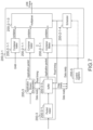
- FIG. 1 is a block diagram showing a schematic configuration of a communications system 1 including two SerDeses, i.e., a SerDes 200 (SerDes # 1 ) and a SerDes 400 (SerDes # 2 ).
- FIG. 1 shows an example in which the SerDes 200 and the SerDes 400 perform serial communication with each other.
- the SerDes 200 and the SerDes 400 which are high-speed serial interface devices, are connected to each other by a cable 300 having the length of several to ten and several meters.
- An ECU 100 is connected to the SerDes 200 , and a peripheral device 500 (Peripheral # 1 ) and a peripheral device 600 (Peripheral # 2 ) are connected to the SerDes 400 .
- the ECU 100 performs processing of receiving main data such as a video signal and transmitting the received data, and transmits/receives an SPI (Serial Peripheral Interface) signal, an I2C (Inter-Integrated Circuit) signal, a GPIO (general purpose IO) signal, or the like to control the whole system.
- SPI Serial Peripheral Interface
- I2C Inter-Integrated Circuit
- GPIO General purpose IO
- the peripheral device 500 connected to the SerDes 400 transmits high-speed and large-capacity main data such as a video signal, and transmits/receives a control signal by SPI or GPIO. Further, the peripheral device 600 connected to the SerDes 400 transmits/receives a low-speed signal such as observation data and a control signal by I2C or GPIO.
- the communications system including the two SerDeses 200 and 400 shown in FIG. 1 is provided in various apparatuses such as an in-vehicle camera module.
- FPD-LINK As an interface technology for serial communication between the two SerDeses 200 and 400 , FPD-LINK has been known.
- Automotive SerDes Alliance ASA
- ASA Automotive SerDes Alliance
- the difference between FPD-LINK and ASA is that ASA uses Time Division Duplex (TDD) while FPD-LINK uses Frequency Division Duplex (FDD) as a method for realizing two-way communication.
- TDD Time Division Duplex
- FDD Frequency Division Duplex
- the packet transmission timing and the frequency band of FDD are illustrated in the lower left of FIG. 1
- the packet transmission timing and the frequency band of ASA are illustrated in the lower right of FIG. 1 .
- a Down Link and an UP Link use difference frequency bands to transmit/receive packets in parallel during an overlapping period.
- a Down Link and an UP Link use an overlapping frequency band to transmit/receive packets in time division.
- FIG. 2 is a block diagram of the communications system 1 embodying the internal configuration of the SerDeses 200 and 400 .
- FIG. 2 shows an example in which an application includes an SPI signal, an I2C signal, and a GPIO signal.
- the SerDes 200 includes a PHY unit (PHY block) 200 - 1 , a LINK unit (LINK block) 200 - 2 , a plurality of encapsulators (Application Stream Encapsulators) 200 - 3 , a plurality of de-encapsulators (Application Stream De-encapsulators) 200 - 4 , and a control register (Control registers) 200 - 5 .
- the PHY unit 200 - 1 includes an UP Link transmission unit (UP Link Tx) 200 - 1 - 1 and a Down Link transmission unit (Down Link Rx) 200 - 1 - 2 .
- the LINK unit 200 - 2 includes a frame construction unit (Frame Constructor) 200 - 2 - 1 , a frame deconstruction unit (Frame De-constructor) 200 - 2 - 2 , and an OAM (Operation Administration Maintenance) unit 200 - 2 - 3 .
- the ECU 100 generates an SPI signal, an I2C signal, and a GPIO signal, which are control signals, as necessary for processing, and outputs the generated signal to the SerDes 200 .
- the plurality of encapsulators 200 - 3 in the SerDes 200 is provided for each application (e.g., each of the SPI signal, the I2C signal, and the GPIO signal). Each of the encapsulators 200 - 3 generates a corresponding application packet.
- the encapsulator 200 - 3 for an SPI signal receives an SPI signal from the ECU 100 and generates an application packet including the SPI signal.
- the encapsulator 200 - 3 for an I2C signal receives an I2C signal from the ECU 100 and generates an application packet including the I2C signal.
- the encapsulator 200 - 3 for a GPIO signal receives a GPIO signal from the ECU 100 and generates an application packet including the GPIO signal.
- the plurality of de-encapsulators 200 - 4 in the SerDes 200 is provided for each application.
- the de-encapsulator 200 - 4 for main data restores main data from the received application packet and transmits the restored main data to the ECU 100 .
- the de-encapsulator 200 - 4 for an SPI signal restores an SPI signal from the received application packet and transmits the restored SPI signal to the ECU 100 .
- the de-encapsulator 200 - 4 for an I2C signal restores an I2C signal from the received application packet and transmits the restored I2C signal to the ECU 100 .
- the de-encapsulator 200 - 4 for a GPIO signal restores a GPIO signal from the received application packet and transmits the restored GPIO signal to the ECU 100 .
- FIG. 3 is a diagram showing a configuration of an application packet generated by the plurality of encapsulators 200 - 3 , a link frame generated by the LINK unit 200 - 2 , and a transmission symbol to be transmitted by the PHY unit 200 - 1 .
- the application packet includes a packet header and application packet data.
- the LINK unit 200 - 2 generates a container for each of the plurality of encapsulators 200 - 3 , and generates a link frame including a plurality of containers.
- the container includes a container header and a container payload.
- the container header includes address information of a device on the reception side supplied from the control register 200 - 5 and address information of the de-encapsulator 200 - 4 .
- the link frame generated by the LINK unit 200 - 2 is supplied to the UP Link transmission unit 200 - 1 - 1 of the PHY unit 200 - 1 .
- the UP Link transmission unit 200 - 1 - 1 adds a sync header that is necessary for synchronization processing on the reception side to the link frame (( 3 - 3 ) in FIG. 3 ) to generate a transmission frame (( 3 - 4 ) in FIG. 3 ), and then performs modulation processing such as binary transmission (NRZ) and quadrature transmission (PAM4) to convert the transmission frame into a transmission symbol (( 3 - 5 ) in FIG. 3 ) and outputs the obtained transmission symbol to the cable 300 .
- modulation processing such as binary transmission (NRZ) and quadrature transmission (PAM4)
- One transmission frame (( 3 - 4 ) in FIG. 3 ) is transmitted within one TDD time slot of a TDD method.
- TDD method Down Link transmission and UP Link transmission are performed once at different timings within one TDD burst period.
- the above-mentioned transmission frame is transmitted within, for example, a Down Link transmission period.
- the UP Link transmits only a control signal and the Down Link transmits a video signal including a control signal, or the like
- the Down Link basically occupies a larger amount of time and the time ratio is 1:several tens.
- FIG. 4 is a block diagram showing the internal configuration of the frame construction unit 200 - 2 - 1 in the SerDes 200 in FIG. 2 .
- the frame construction unit 200 - 2 - 1 includes a plurality of container makers (container makers) 200 - 2 - 1 - 1 corresponding to the plurality of encapsulators 200 - 3 , a multiplexer 200 - 2 - 1 - 3 , and a scheduler 200 - 2 - 1 - 2 .
- Each of the encapsulators 200 - 3 includes a packet maker (Packet maker) 200 - 3 - 1 and a buffer 200 - 3 - 3 .
- Packet maker Packet maker
- the application packet generated by the packet maker 200 - 3 - 1 is once stored in the buffer 200 - 3 - 3 and then input to the corresponding container maker 200 - 2 - 1 - 1 in the frame construction unit 200 - 2 - 1 in accordance with an instruction from the scheduler 200 - 2 - 1 - 2 .
- Each of the container makers 200 - 2 - 1 - 1 receives a corresponding application packet from the corresponding encapsulator 200 - 3 or the OAM unit 200 - 2 - 3 to generate a corresponding container.
- the container generated by each of the container makers 200 - 2 - 1 - 1 is input to the multiplexer 200 - 2 - 1 - 3 .
- the scheduler 200 - 2 - 1 - 2 outputs a timing adjustment signal indicating at which timing each container is output.
- the multiplexer 200 - 2 - 1 - 3 generates a link frame including a plurality of containers on the basis of the timing adjustment signal from the scheduler 200 - 2 - 1 - 2 .
- a schedule according to the transmission band required by an application to be transmitted by the ECU 100 is transferred to the control register 200 - 5 by some means not shown in FIG. 2 .
- the control register 200 - 5 supplies the schedule to the scheduler 200 - 2 - 1 - 2 . Therefore, control is performed such that the container for transmitting wideband information such as a video signal is selected more often by the multiplexer 200 - 2 - 1 - 3 per unit time and a low-speed signal such as GPIO is selected less often.
- an OAM signal including the schedule generated by the ECU 100 is supplied also to the scheduler in a frame construction unit 400 - 2 - 1 of the SerDes 400 via the UP Link.
- the SerDes 400 includes a PHY unit (PHY block) 400 - 1 , a LINK unit (LINK block) 400 - 2 , a plurality of encapsulators (Application Stream Encapsulator) 400 - 3 , a plurality of de-encapsulators (Application Stream De-encapsulator) 400 - 4 , and a control register (Control registers) 400 - 5 .
- the PHY unit 400 - 1 includes a Down Link transmission unit (Down Link Tx) 400 - 1 - 1 and an UP Link reception unit (UP Link Rx) 400 - 1 - 2 .
- the LINK unit 400 - 2 includes a frame construction unit 400 - 2 - 1 , a frame deconstruction unit 400 - 2 - 2 , and an OAM unit 400 - 2 - 3 .
- the encapsulator 400 - 3 for main data receives main data from the peripheral device 500 and generates an application packet including the main data.
- the encapsulator 400 - 3 for an SPI signal receives an SPI signal from the peripheral device 500 and generates an application packet including the SPI signal.
- the encapsulator 400 - 3 for a GPIO signal receives a GPIO signal from the peripheral device 500 and generates an application packet including the GPIO signal.
- the de-encapsulator 400 - 4 for an I2C signal restores an I2C signal from the received packet and transmits the restored I2C signal to the peripheral device 600 .
- the de-encapsulator 400 - 4 for a GPIO signal restores a GPIO signal from the received packet and transmits the restored GPIO signal to the peripheral device 600 .
- the SerDes 400 generates a lock synchronized with a symbol frequency with the sync signal added to the top of the transmission symbol (( 3 - 5 ) in FIG. 3 ) received from the SerDes 200 to reproduce the transmission frame ((3-4) in FIG. 3 ).
- the sync header is removed from the reproduced transmission frame (( 3 - 4 ) in FIG. 3 ) to generate the link frame (( 3 - 3 ) in FIG. 3 ) and the generated link frame is input to the frame deconstruction unit 400 - 2 - 2 in the LINK unit 400 - 2 .
- the frame deconstruction unit 400 - 2 - 2 divides the link frame (( 3 - 3 ) in FIG. 3 ) into containers (( 3 - 2 ) in FIG. 3 ), acquires address information of the de-encapsulator 400 - 4 from the container header of each container, and outputs, to the corresponding de-encapsulator 400 - 4 , the application packet (( 3 - 1 ) in FIG. 3 ) included in the container payload of the container.
- Each of the de-encapsulators 400 - 4 reconstructs, on the basis of the packet header in the corresponding application packet, the application packet data in the application packet into the format of each application and outputs the obtained data to the corresponding peripheral device 500 or 600 .
- the number of times per unit time and the transmission order for transmitting a container (( 3 - 2 ) in FIG. 3 ) that stores each application to be transmitted are determined in advance at the time of system design.
- the latency for each application becomes substantially constant and problems such as transmission jitter of an application are avoided.
- This is very convenient in the case where large-capacity data such as a video signal is constantly transmitted.
- the transmission band required by each of an SPI signal, an I2C signal, and a GPIO signal for mainly controlling a peripheral device may be narrower than that of the video signal.
- FIG. 5 is a diagram showing the transmission timing of the SerDes 200 in FIG. 2 .
- FIG. 5 shows an example in which the frame construction unit 200 - 2 - 1 on the UP Link side sets the transmission schedule of each application packet With 6 TDD time slots as one period.
- one application packet is transmitted for each TDD time slot in the UP Link (( 5 - 1 ) in FIG. 5 ).
- the application packet including an OAM signal is transmitted once every 6 TDD time slots
- an application packet including an SPI signal is transmitted four times every 6 TDD time slots
- an application packet including a GPIO signal and an application packet including an I2C signal are transmitted once every 12 TDD time slots (( 5 - 2 ) in FIG. 5 ).
- the SPI signal, the I2C signal, and the GPIO signal to be input to the SerDes 200 are once input to the encapsulator 200 - 3 , converted into a corresponding application packet, and then, buffered and input to the frame construction unit 200 - 2 - 1 in accordance with the read timing of the scheduler 200 - 2 - 1 - 2 .
- the read timing determined by the scheduler 200 - 2 - 1 - 2 coincides with the transmission schedule of each application shown in Parts ( 5 - 1 ) and ( 5 - 2 ) of FIG. 5 .
- application packets SPI #m and #m+1 of an SPI signal are respectively transmitted in TDD time slots # 9 and # 10 (( 5 - 3 ) in FIG. 5 ), and application packets GPI #n and #n+1 of a GPIO signal (( 5 - 5 ) in FIG. 5 ) are respectively transmitted in TDD time slots # 14 and # 26 (( 5 - 2 ) in FIG. 5 ).
- FIG. 6 is a diagram showing the transmission timing in the case where an I2C signal has been input from the ECU 100 to the SerDes 200 .
- an application packet of an I2C signal is transmitted in a TDD time slot # 20 .
- the change in the GPI signal (( 5 - 6 ) in FIG. 5 ) input from the ECU 100 has occurred near TDD time slots # 2 to # 3 , but the timing at which this change is packetized and transmitted is a TDD time slot # 26 , which causes transmission latency. For example, in the case where 1 TDD burst period is approximately 30 usec, transmission latency of approximately 690 usec occurs.
- the communication apparatus and the communications system according to the embodiment of the present disclosure are characterized in that the transmission efficiency is improved while minimizing the transmission latency when transmitting, by a TDD transmission method, a plurality of applications to which a transmission schedule has been assigned in advance.
- FIG. 7 is a block diagram of the frame construction unit 200 - 2 - 1 according to a first embodiment of the present disclosure.
- the frame construction unit 200 - 2 - 1 in FIG. 7 includes a plurality of container makers (container makers) 200 - 2 - 1 - 1 corresponding to the plurality of encapsulators 200 - 3 , the multiplexer 200 - 2 - 1 - 3 , and a scheduler 200 - 2 - 1 - 4 .
- each of the encapsulators 200 - 3 shown in FIG. 7 stores, in the corresponding buffer 200 - 3 - 3 , an application packet generated by the corresponding packet maker 200 - 3 - 1 , and then outputs a data ready signal.
- the data ready signal is a signal indicating that a valid application packet is stored in the corresponding buffer 200 - 3 - 3 .
- the data ready signal from each of the encapsulators 200 - 3 is input to the scheduler 200 - 2 - 1 - 4 .
- the scheduler 200 - 2 - 1 - 4 controls, on the basis of the data ready signal from each of the encapsulators 200 - 3 , the order of causing the container generated by each of the container makers 200 - 2 - 1 - 1 to be included in the transmission frame.
- FIG. 8 is a flowchart showing the processing operation of the scheduler 200 - 2 - 1 - 4 in FIG. 7 .
- FIG. 9 is a diagram showing the transmission timing in the UP Link according to this embodiment.
- the processing operation of the communication apparatus and the communications system according to this embodiment will be described on the basis of FIG. 7 to FIG. 9 .
- the scheduler 200 - 2 - 1 - 4 in FIG. 7 determines in advance, before the communications system starts transmission, which application packet is assigned to which TDD time slot and transmitted by the schedule management from the ECU 100 via the control register 200 - 5 .
- the ECU 100 or the control register 200 - 5 prepares a specific TDD time slot (shared time slot) in the scheduler 200 - 2 - 1 - 4 , and assigns, to the shared time slot, not one application packet but a plurality of application packets.
- a signal such as a control signal, which has a relatively small transmission band and a low transmission frequency, is assigned to this application packet transmitted in the specific shared time slot.
- the ECU 100 or the control register 200 - 5 sets, for the scheduler 200 - 2 - 1 - 4 , the output priority of the application packet assigned to the shared time slot. How many shared time slots are prepared, which application packet is assigned, and how the priority is set are changed in accordance with the system and the operation situation.
- the priority may be determined at the time of system design, for example. That is, the order in which the priority is periodically changed may be determined at the time of system design and stored in a memory, a resister, or the like (not shown).
- a user may set the priority or the order in which the priority is changed using a, updatable value of a resister. In this case, the user can change the priority or the order in which the priority is changed by updating the value of the resister at an appropriate timing.
- the scheduler 200 - 2 - 1 - 4 determines whether or not the TDD time slot to be scheduled is the shared time slot (Step S 1 ). For example, TDD time slots # 2 , # 8 , # 14 , # 20 , and # 26 in FIG. 9 are determined to be the shared time slots.
- Step S 2 whether or not the application packet having the highest priority is stored in the corresponding buffer 200 - 3 - 3 is determined by the data ready signal (Step S 2 ).
- the application packet having the highest priority is stored in the buffer 200 - 3 - 3
- it is determined that the application packet has been prepared a container is generated by the container maker 200 - 2 - 1 - 1 corresponding to the application packet stored in the buffer 200 - 3 - 3 , and the generated container is selected by the multiplexer 200 - 2 - 1 - 3 to form a link frame (Step S 3 ).
- the priority of the shared time slot is changed by one level (Step S 4 ).
- the priority of each of five shared time slots # 2 , # 8 , # 14 , # 20 , and # 26 in FIG. 9 is changed as follows. Note that the following is just an example, and the order in which the priority is changed is arbitrary.
- Step S 1 and subsequent Steps is repeated. More specifically, for example, in FIG. 9 , the priority of the TDD time slot # 2 satisfies the relationship of GPIO>I2C, the priority of the next TDD time slot # 8 satisfies the relationship of I2C>GPIO, and the priority of the next TDD time slot # 14 satisfies the relationship of GPIO>I2C similarly to the original. As a result, it is possible to guarantee the transmission band originally assigned to the application packet. As described above, the priority of the shared time slot is switched in order for every one period.
- Step S 5 When it is determined in Step S 2 that the application packet is not stored in the buffer 200 - 3 - 3 , whether or not there is an application packet having the next highest priority is determined (Step S 5 ). When it is determined that there is an application packet having the next highest priority, whether or not the determined application packet is stored in the corresponding buffer 200 - 3 - 3 is determined by the data ready signal (Step S 6 ). When it is determined that the determined application packet is stored in the corresponding buffer 200 - 3 - 3 , the processing proceeds to Step S 3 . For example, although the application packet including an I2C signal has the highest priority in the TDD time slot # 8 in FIG.
- Step S 9 the I2C signal is null at this time point and the application packet including an I2C signal is not stored in the corresponding buffer 200 - 3 - 3 .
- the determination in Step S 2 in FIG. 8 is NO, the processing proceeds to Step S 5 , and whether or not there is an application packet having the next highest priority is determined.
- the GPIO signal has the next highest priority of the I2C signal.
- the application packet including a GPIO signal is stored in the corresponding buffer 200 - 3 - 3 (GPI #n+1 Part 9 - 5 of FIG. 9 ).
- the container maker 200 - 2 - 1 - 1 corresponding to this application packet generates a container including this application packet.
- Step S 5 the processing proceeds to Step S 4 .
- the application packet including a GPIO signal has the highest priority.
- an application to be transmitted is not stored in the buffer 200 - 3 - 3 in the encapsulator 200 - 3 for a GPIO signal.
- the determination is NO in Step S 2 in FIG. 8
- the processing proceeds to Step S 5 , and whether or not there is an application packet having the next highest priority is determined.
- the I2C signal has the next highest priority.
- Step S 5 the determination is NO in Step S 5 , and the priority of the shared time slot is switched in Step S 4 .
- Step S 1 When it is determined in Step S 1 that the TDD time slot to be scheduled is not the shared time slot, the scheduler 200 - 2 - 1 - 4 selects the designated application packet, a container corresponding to the selected application packet is generated by the container maker 200 - 2 - 1 - 1 , and the generated container is selected by the multiplexer 200 - 2 - 1 - 3 to form a link frame (Step S 7 ). When the processing of Step S 7 is finished, the processing of Step S 1 and subsequent Steps is repeated.
- one period including a plurality of TDD time slots includes a shared time slot capable of transmitting a packet including one of a plurality of types of serial signals. Since a plurality of types of application packets each including an application signal having a low transmission frequency is transmitted in the shared time slot and the priority when transmitting the plurality of types of application packets in the shared time slot is changed in order, it is possible to transmit the plurality of types of application packets with equal transmission latency.
- a second embodiment is different from the first embodiment in the configuration of the frame construction unit 200 - 2 - 1 in the LINK unit 200 - 2 and the surroundings thereof.
- FIG. 10 is a block diagram showing a configuration of the frame construction unit 200 - 2 - 1 according to the second embodiment and the surroundings thereof.
- a packet selector 200 - 6 is disposed between the plurality of encapsulators 200 - 3 and the frame construction unit 200 - 2 - 1 .
- the packet selector 200 - 6 executes part of functions of the scheduler 200 - 2 - 1 - 4 in FIG. 7 .
- the packet selector 200 - 6 is connected to two or more encapsulators 200 - 3 each transmitting an application packet in the shared time slot.
- Each of the two or more encapsulators 200 - 3 connected to the packet selector 200 - 6 includes the packet maker 200 - 3 - 1 and the buffer 200 - 3 - 3 .
- Each of the encapsulators 200 - 3 outputs the data ready signal when an application packet is stored in the corresponding buffer 200 - 3 - 3 .
- the data ready signal is input to the packet selector 200 - 6 .
- the packet selector 200 - 6 selects, on the basis of the data ready signal from the two or more encapsulators 200 - 3 each transmitting an application packet in the shared time slot, an application packet to be transmitted in the shared time slot.
- the data ready signal is a signal indicating that the corresponding application packet is stored in the corresponding buffer 200 - 3 - 3 , and is output from the corresponding encapsulator 200 - 3 .
- the application packet transmitted in the shared time slot is input to the frame construction unit 200 - 2 - 1 .
- the frame construction unit 200 - 2 - 1 in FIG. 10 includes a plurality of container makers 200 - 2 - 1 - 1 (Container makers) corresponding to the plurality of encapsulators 200 - 3 or the OAM unit 200 - 2 - 3 , the multiplexer 200 - 2 - 1 - 3 , and the scheduler 200 - 2 - 1 - 5 .
- the scheduler 200 - 2 - 1 - 5 in FIG. 10 is different from the scheduler 200 - 2 - 1 - 4 in FIG. 7 .
- the frame construction unit 200 - 2 - 1 in FIG. 7 includes the same number of the container makers 200 - 2 - 1 - 1 as the plurality of encapsulators 200 - 3
- the frame construction unit 200 - 2 - 1 in FIG. 10 includes the container makers 200 - 2 - 1 - 1 whose number is smaller than that of the plurality of encapsulators 200 - 3 . More specifically, one of a plurality of application packets to be transmitted in the shared time slot is selected by the packet selector 200 - 6 , and the selected application packet is input to the dedicated container maker 200 - 2 - 1 - 1 .
- a read timing signal informing the timing of the shared time slot is input from the scheduler 200 - 2 - 1 - 5 to the packet selector 200 - 6 .
- the packet selector 200 - 6 performs, when a read timing signal is input, the processing operation similar to that in the flowchart shown in FIG. 8 .
- the packet selector 200 - 6 transmits, when selecting an application packet to be transmitted in the shared time slot, the application packet to the corresponding container maker 200 - 2 - 1 - 1 together with packet information indicating which application the application corresponds to.
- the corresponding container maker 200 - 2 - 1 - 1 generates, on the basis of the received packet information, a container header together with a container payload including the received application packet to complete a container.
- the scheduler 200 - 2 - 1 - 5 in the frame construction unit 200 - 2 - 1 selects, setting information of the control register 200 - 5 , a plurality of containers generated by the plurality of container makers 200 - 2 - 1 - 1 one by one to generate a link frame.
- the packet selector 200 - 6 is provided between the plurality of encapsulators 200 - 3 and the frame construction unit 200 - 2 - 1 to select an application packet to be transmitted in the shared time slot, it is possible to reduce the number of the container makers 200 - 2 - 1 - 1 in the frame construction unit 200 - 2 - 1 . Further, since the packet selector 200 - 6 performs part of the processing of schedule management of the scheduler 200 - 2 - 1 - 5 , it is possible to reduce the processing load of the scheduler 200 - 2 - 1 - 5 and simplify the internal configuration of the frame construction unit 200 - 2 - 1 .
- a communication apparatus including:
Landscapes
- Engineering & Computer Science (AREA)
- Signal Processing (AREA)
- Computer Networks & Wireless Communication (AREA)
- Time-Division Multiplex Systems (AREA)
Priority Applications (6)
| Application Number | Priority Date | Filing Date | Title |
|---|---|---|---|
| US17/536,772 US11863500B2 (en) | 2021-02-25 | 2021-11-29 | Communication apparatus, communications system, and communication method |
| US18/546,982 US20240146494A1 (en) | 2021-02-25 | 2022-02-18 | Communication apparatus, communication system, and communication method |
| CN202280015971.6A CN116964965A (zh) | 2021-02-25 | 2022-02-18 | 通信装置、通信系统和通信方法 |
| PCT/JP2022/006610 WO2022181476A1 (ja) | 2021-02-25 | 2022-02-18 | 通信装置、通信システム及び通信方法 |
| KR1020237028139A KR20230151515A (ko) | 2021-02-25 | 2022-02-18 | 통신 장치, 통신 시스템 및 통신 방법 |
| JP2023502348A JPWO2022181476A1 (ja) | 2021-02-25 | 2022-02-18 |
Applications Claiming Priority (2)
| Application Number | Priority Date | Filing Date | Title |
|---|---|---|---|
| US202163153536P | 2021-02-25 | 2021-02-25 | |
| US17/536,772 US11863500B2 (en) | 2021-02-25 | 2021-11-29 | Communication apparatus, communications system, and communication method |
Related Child Applications (1)
| Application Number | Title | Priority Date | Filing Date |
|---|---|---|---|
| US18/546,982 Continuation US20240146494A1 (en) | 2021-02-25 | 2022-02-18 | Communication apparatus, communication system, and communication method |
Publications (2)
| Publication Number | Publication Date |
|---|---|
| US20220271910A1 US20220271910A1 (en) | 2022-08-25 |
| US11863500B2 true US11863500B2 (en) | 2024-01-02 |
Family
ID=82901043
Family Applications (2)
| Application Number | Title | Priority Date | Filing Date |
|---|---|---|---|
| US17/536,772 Active 2042-01-19 US11863500B2 (en) | 2021-02-25 | 2021-11-29 | Communication apparatus, communications system, and communication method |
| US18/546,982 Pending US20240146494A1 (en) | 2021-02-25 | 2022-02-18 | Communication apparatus, communication system, and communication method |
Family Applications After (1)
| Application Number | Title | Priority Date | Filing Date |
|---|---|---|---|
| US18/546,982 Pending US20240146494A1 (en) | 2021-02-25 | 2022-02-18 | Communication apparatus, communication system, and communication method |
Country Status (5)
| Country | Link |
|---|---|
| US (2) | US11863500B2 (ja) |
| JP (1) | JPWO2022181476A1 (ja) |
| KR (1) | KR20230151515A (ja) |
| CN (1) | CN116964965A (ja) |
| WO (1) | WO2022181476A1 (ja) |
Citations (17)
| Publication number | Priority date | Publication date | Assignee | Title |
|---|---|---|---|---|
| JPH06245250A (ja) | 1992-11-27 | 1994-09-02 | Nec Corp | 移動通信システム |
| JPH09116520A (ja) | 1995-10-20 | 1997-05-02 | Mitsubishi Electric Corp | 多重化装置 |
| JP2000209177A (ja) | 1999-01-11 | 2000-07-28 | Mitsubishi Electric Corp | 多重化装置 |
| US20070061433A1 (en) * | 2005-09-12 | 2007-03-15 | Scott Reynolds | Methods and apparatus to support dynamic allocation of traffic management resources in a network element |
| US20070237150A1 (en) * | 2006-04-06 | 2007-10-11 | Wood Samuel F | Self-Routed Layer 4 Packet Network System and Method |
| US20080109579A1 (en) * | 2006-11-08 | 2008-05-08 | Jinlei Liu | System and method for frequency offset testing |
| US20120201138A1 (en) * | 2011-02-07 | 2012-08-09 | Brocade Communications Systems, Inc. | Quality of service in a heterogeneous network |
| US20140181319A1 (en) * | 2012-12-26 | 2014-06-26 | Cortina Systems, Inc. | Communication traffic processing architectures and methods |
| US8860774B1 (en) * | 2013-06-11 | 2014-10-14 | New Vad, Llc | System and method for PC-based video conferencing and audio/video presentation |
| JP2015519799A (ja) | 2012-04-16 | 2015-07-09 | エントロピック・コミュニケーションズ・インコーポレイテッドEntropic Communications, Inc. | ダウンストリームアクセスのための順次変調 |
| US20150263916A1 (en) * | 2014-03-17 | 2015-09-17 | Ericsson Television Inc. | Bandwidth management in a content distribution network |
| US20150373075A1 (en) * | 2014-06-23 | 2015-12-24 | Radia Perlman | Multiple network transport sessions to provide context adaptive video streaming |
| US20170054688A1 (en) * | 2015-08-20 | 2017-02-23 | Cisco Technology, Inc. | Avc bi-directional correlation using an overlay fabric header |
| JP2019004216A (ja) | 2017-06-12 | 2019-01-10 | 日立ジョンソンコントロールズ空調株式会社 | 通信制御装置、および、設備通信システム |
| US20190057048A1 (en) * | 2017-08-16 | 2019-02-21 | Mediatek Inc. | Wireless communication method and system |
| US20210400709A1 (en) * | 2020-06-19 | 2021-12-23 | Qualcomm Incorporated | Uplink traffic prioritization across multiple links |
| US20220006883A1 (en) * | 2021-09-16 | 2022-01-06 | Intel Corporation | System, apparatus, and method for packet-based network transport including a unified adapter layer |
Family Cites Families (1)
| Publication number | Priority date | Publication date | Assignee | Title |
|---|---|---|---|---|
| JP5535753B2 (ja) | 2010-05-06 | 2014-07-02 | 株式会社日立国際電気 | 無線基地局装置 |
-
2021
- 2021-11-29 US US17/536,772 patent/US11863500B2/en active Active
-
2022
- 2022-02-18 US US18/546,982 patent/US20240146494A1/en active Pending
- 2022-02-18 JP JP2023502348A patent/JPWO2022181476A1/ja active Pending
- 2022-02-18 WO PCT/JP2022/006610 patent/WO2022181476A1/ja active Application Filing
- 2022-02-18 KR KR1020237028139A patent/KR20230151515A/ko unknown
- 2022-02-18 CN CN202280015971.6A patent/CN116964965A/zh active Pending
Patent Citations (17)
| Publication number | Priority date | Publication date | Assignee | Title |
|---|---|---|---|---|
| JPH06245250A (ja) | 1992-11-27 | 1994-09-02 | Nec Corp | 移動通信システム |
| JPH09116520A (ja) | 1995-10-20 | 1997-05-02 | Mitsubishi Electric Corp | 多重化装置 |
| JP2000209177A (ja) | 1999-01-11 | 2000-07-28 | Mitsubishi Electric Corp | 多重化装置 |
| US20070061433A1 (en) * | 2005-09-12 | 2007-03-15 | Scott Reynolds | Methods and apparatus to support dynamic allocation of traffic management resources in a network element |
| US20070237150A1 (en) * | 2006-04-06 | 2007-10-11 | Wood Samuel F | Self-Routed Layer 4 Packet Network System and Method |
| US20080109579A1 (en) * | 2006-11-08 | 2008-05-08 | Jinlei Liu | System and method for frequency offset testing |
| US20120201138A1 (en) * | 2011-02-07 | 2012-08-09 | Brocade Communications Systems, Inc. | Quality of service in a heterogeneous network |
| JP2015519799A (ja) | 2012-04-16 | 2015-07-09 | エントロピック・コミュニケーションズ・インコーポレイテッドEntropic Communications, Inc. | ダウンストリームアクセスのための順次変調 |
| US20140181319A1 (en) * | 2012-12-26 | 2014-06-26 | Cortina Systems, Inc. | Communication traffic processing architectures and methods |
| US8860774B1 (en) * | 2013-06-11 | 2014-10-14 | New Vad, Llc | System and method for PC-based video conferencing and audio/video presentation |
| US20150263916A1 (en) * | 2014-03-17 | 2015-09-17 | Ericsson Television Inc. | Bandwidth management in a content distribution network |
| US20150373075A1 (en) * | 2014-06-23 | 2015-12-24 | Radia Perlman | Multiple network transport sessions to provide context adaptive video streaming |
| US20170054688A1 (en) * | 2015-08-20 | 2017-02-23 | Cisco Technology, Inc. | Avc bi-directional correlation using an overlay fabric header |
| JP2019004216A (ja) | 2017-06-12 | 2019-01-10 | 日立ジョンソンコントロールズ空調株式会社 | 通信制御装置、および、設備通信システム |
| US20190057048A1 (en) * | 2017-08-16 | 2019-02-21 | Mediatek Inc. | Wireless communication method and system |
| US20210400709A1 (en) * | 2020-06-19 | 2021-12-23 | Qualcomm Incorporated | Uplink traffic prioritization across multiple links |
| US20220006883A1 (en) * | 2021-09-16 | 2022-01-06 | Intel Corporation | System, apparatus, and method for packet-based network transport including a unified adapter layer |
Also Published As
| Publication number | Publication date |
|---|---|
| CN116964965A (zh) | 2023-10-27 |
| US20240146494A1 (en) | 2024-05-02 |
| JPWO2022181476A1 (ja) | 2022-09-01 |
| US20220271910A1 (en) | 2022-08-25 |
| KR20230151515A (ko) | 2023-11-01 |
| WO2022181476A1 (ja) | 2022-09-01 |
Similar Documents
| Publication | Publication Date | Title |
|---|---|---|
| JP6602917B2 (ja) | Rat間二重接続性ue用のtdm伝送 | |
| EP2744290B1 (en) | Method and user device for sending data | |
| US6940831B1 (en) | Wireless communications system | |
| US11438919B2 (en) | TDD single Tx switched UL solution | |
| JP6998307B2 (ja) | 端末及び通信方法 | |
| US20050226198A1 (en) | Multiplex communication with slotted retransmission on demand | |
| JPH10257097A (ja) | 広帯域デジタル無線システムにおける通信方法及び広帯域デジタル無線通信端末 | |
| JPWO2006013641A1 (ja) | 集積回路装置及び信号伝送システム | |
| CN111817824B (zh) | 一种信息传输方法、终端设备和控制节点 | |
| US20170019220A1 (en) | Multiband Ethernet Over Coax System | |
| US7894415B2 (en) | Apparatus and method for transmitting/receiving resource allocation information in a communication system | |
| US11863500B2 (en) | Communication apparatus, communications system, and communication method | |
| WO2012034584A1 (en) | Method of and base station for configuring a data transmission scheme based on data frames in a communication network | |
| CN107493604A (zh) | 帧结构配置的方法与装置 | |
| KR20200098259A (ko) | 통신 시스템에서의 효율적인 프론트홀을 이용한 신호 전송 방법 및 장치 | |
| WO2013073918A1 (ko) | 시분할 이중화 통신 시스템에서 물리채널 송수신의 제어 방법 및 장치 | |
| CN110351046A (zh) | 通信方法、通信装置和系统 | |
| JP2006304011A (ja) | インタフェース回路 | |
| US20100014488A1 (en) | Mobile Communication System and Base Station Device | |
| CN112702797A (zh) | 无线电模块及其操作方法、无线电终端及其操作方法 | |
| CN102195705A (zh) | 下行基带数据发送方法和基站 | |
| CN115004809A (zh) | 一种确定侧链路时长的方法及其装置 | |
| US20240179713A1 (en) | Uplink control information transmission method and apparatus, and related device | |
| EP2207397B1 (en) | Method for efficient utilization of radio resources for transmission of video streams in a wireless communications system | |
| US6084861A (en) | Radio communication system |
Legal Events
| Date | Code | Title | Description |
|---|---|---|---|
| FEPP | Fee payment procedure |
Free format text: ENTITY STATUS SET TO UNDISCOUNTED (ORIGINAL EVENT CODE: BIG.); ENTITY STATUS OF PATENT OWNER: LARGE ENTITY |
|
| AS | Assignment |
Owner name: SONY SEMICONDUCTOR SOLUTIONS CORPORATION, JAPAN Free format text: ASSIGNMENT OF ASSIGNORS INTEREST;ASSIGNORS:HYAKUDAI, TOSHIHISA;OTA, SATOSHI;YAMADA, JUNYA;SIGNING DATES FROM 20210113 TO 20220106;REEL/FRAME:058647/0113 |
|
| STPP | Information on status: patent application and granting procedure in general |
Free format text: DOCKETED NEW CASE - READY FOR EXAMINATION |
|
| STPP | Information on status: patent application and granting procedure in general |
Free format text: NON FINAL ACTION MAILED |
|
| STPP | Information on status: patent application and granting procedure in general |
Free format text: RESPONSE TO NON-FINAL OFFICE ACTION ENTERED AND FORWARDED TO EXAMINER |
|
| STPP | Information on status: patent application and granting procedure in general |
Free format text: NOTICE OF ALLOWANCE MAILED -- APPLICATION RECEIVED IN OFFICE OF PUBLICATIONS |
|
| STPP | Information on status: patent application and granting procedure in general |
Free format text: PUBLICATIONS -- ISSUE FEE PAYMENT RECEIVED |
|
| STPP | Information on status: patent application and granting procedure in general |
Free format text: PUBLICATIONS -- ISSUE FEE PAYMENT VERIFIED |
|
| STCF | Information on status: patent grant |
Free format text: PATENTED CASE |