US11794442B2 - Superposition interior component - Google Patents
Superposition interior component Download PDFInfo
- Publication number
- US11794442B2 US11794442B2 US17/598,898 US201917598898A US11794442B2 US 11794442 B2 US11794442 B2 US 11794442B2 US 201917598898 A US201917598898 A US 201917598898A US 11794442 B2 US11794442 B2 US 11794442B2
- Authority
- US
- United States
- Prior art keywords
- protrusions
- base
- outer layer
- superposition
- interior component
- Prior art date
- Legal status (The legal status is an assumption and is not a legal conclusion. Google has not performed a legal analysis and makes no representation as to the accuracy of the status listed.)
- Active, expires
Links
- 229920003023 plastic Polymers 0.000 claims abstract description 15
- 239000004033 plastic Substances 0.000 claims abstract description 15
- 230000004308 accommodation Effects 0.000 claims description 48
- 230000008878 coupling Effects 0.000 claims description 14
- 238000010168 coupling process Methods 0.000 claims description 14
- 238000005859 coupling reaction Methods 0.000 claims description 14
- 230000000994 depressogenic effect Effects 0.000 description 13
- 239000000463 material Substances 0.000 description 10
- 238000000465 moulding Methods 0.000 description 5
- JOYRKODLDBILNP-UHFFFAOYSA-N Ethyl urethane Chemical compound CCOC(N)=O JOYRKODLDBILNP-UHFFFAOYSA-N 0.000 description 4
- 239000006260 foam Substances 0.000 description 4
- 229920000915 polyvinyl chloride Polymers 0.000 description 4
- 239000004800 polyvinyl chloride Substances 0.000 description 4
- 238000012986 modification Methods 0.000 description 3
- 230000004048 modification Effects 0.000 description 3
- 230000015572 biosynthetic process Effects 0.000 description 2
- 230000007547 defect Effects 0.000 description 2
- 229920001971 elastomer Polymers 0.000 description 2
- 239000000806 elastomer Substances 0.000 description 2
- 239000004743 Polypropylene Substances 0.000 description 1
- 229920000728 polyester Polymers 0.000 description 1
- -1 polypropylene Polymers 0.000 description 1
- 229920001155 polypropylene Polymers 0.000 description 1
- 239000002759 woven fabric Substances 0.000 description 1
Images


Classifications
-
- B—PERFORMING OPERATIONS; TRANSPORTING
- B32—LAYERED PRODUCTS
- B32B—LAYERED PRODUCTS, i.e. PRODUCTS BUILT-UP OF STRATA OF FLAT OR NON-FLAT, e.g. CELLULAR OR HONEYCOMB, FORM
- B32B3/00—Layered products comprising a layer with external or internal discontinuities or unevennesses, or a layer of non-planar shape; Layered products comprising a layer having particular features of form
- B32B3/26—Layered products comprising a layer with external or internal discontinuities or unevennesses, or a layer of non-planar shape; Layered products comprising a layer having particular features of form characterised by a particular shape of the outline of the cross-section of a continuous layer; characterised by a layer with cavities or internal voids ; characterised by an apertured layer
- B32B3/30—Layered products comprising a layer with external or internal discontinuities or unevennesses, or a layer of non-planar shape; Layered products comprising a layer having particular features of form characterised by a particular shape of the outline of the cross-section of a continuous layer; characterised by a layer with cavities or internal voids ; characterised by an apertured layer characterised by a layer formed with recesses or projections, e.g. hollows, grooves, protuberances, ribs
-
- B—PERFORMING OPERATIONS; TRANSPORTING
- B32—LAYERED PRODUCTS
- B32B—LAYERED PRODUCTS, i.e. PRODUCTS BUILT-UP OF STRATA OF FLAT OR NON-FLAT, e.g. CELLULAR OR HONEYCOMB, FORM
- B32B27/00—Layered products comprising a layer of synthetic resin
- B32B27/06—Layered products comprising a layer of synthetic resin as the main or only constituent of a layer, which is next to another layer of the same or of a different material
- B32B27/08—Layered products comprising a layer of synthetic resin as the main or only constituent of a layer, which is next to another layer of the same or of a different material of synthetic resin
-
- B—PERFORMING OPERATIONS; TRANSPORTING
- B32—LAYERED PRODUCTS
- B32B—LAYERED PRODUCTS, i.e. PRODUCTS BUILT-UP OF STRATA OF FLAT OR NON-FLAT, e.g. CELLULAR OR HONEYCOMB, FORM
- B32B27/00—Layered products comprising a layer of synthetic resin
- B32B27/12—Layered products comprising a layer of synthetic resin next to a fibrous or filamentary layer
-
- B—PERFORMING OPERATIONS; TRANSPORTING
- B32—LAYERED PRODUCTS
- B32B—LAYERED PRODUCTS, i.e. PRODUCTS BUILT-UP OF STRATA OF FLAT OR NON-FLAT, e.g. CELLULAR OR HONEYCOMB, FORM
- B32B27/00—Layered products comprising a layer of synthetic resin
- B32B27/30—Layered products comprising a layer of synthetic resin comprising vinyl (co)polymers; comprising acrylic (co)polymers
- B32B27/304—Layered products comprising a layer of synthetic resin comprising vinyl (co)polymers; comprising acrylic (co)polymers comprising vinyl halide (co)polymers, e.g. PVC, PVDC, PVF, PVDF
-
- B—PERFORMING OPERATIONS; TRANSPORTING
- B32—LAYERED PRODUCTS
- B32B—LAYERED PRODUCTS, i.e. PRODUCTS BUILT-UP OF STRATA OF FLAT OR NON-FLAT, e.g. CELLULAR OR HONEYCOMB, FORM
- B32B27/00—Layered products comprising a layer of synthetic resin
- B32B27/32—Layered products comprising a layer of synthetic resin comprising polyolefins
-
- B—PERFORMING OPERATIONS; TRANSPORTING
- B32—LAYERED PRODUCTS
- B32B—LAYERED PRODUCTS, i.e. PRODUCTS BUILT-UP OF STRATA OF FLAT OR NON-FLAT, e.g. CELLULAR OR HONEYCOMB, FORM
- B32B27/00—Layered products comprising a layer of synthetic resin
- B32B27/36—Layered products comprising a layer of synthetic resin comprising polyesters
-
- B—PERFORMING OPERATIONS; TRANSPORTING
- B32—LAYERED PRODUCTS
- B32B—LAYERED PRODUCTS, i.e. PRODUCTS BUILT-UP OF STRATA OF FLAT OR NON-FLAT, e.g. CELLULAR OR HONEYCOMB, FORM
- B32B3/00—Layered products comprising a layer with external or internal discontinuities or unevennesses, or a layer of non-planar shape; Layered products comprising a layer having particular features of form
- B32B3/02—Layered products comprising a layer with external or internal discontinuities or unevennesses, or a layer of non-planar shape; Layered products comprising a layer having particular features of form characterised by features of form at particular places, e.g. in edge regions
- B32B3/06—Layered products comprising a layer with external or internal discontinuities or unevennesses, or a layer of non-planar shape; Layered products comprising a layer having particular features of form characterised by features of form at particular places, e.g. in edge regions for securing layers together; for attaching the product to another member, e.g. to a support, or to another product, e.g. groove/tongue, interlocking
-
- B—PERFORMING OPERATIONS; TRANSPORTING
- B32—LAYERED PRODUCTS
- B32B—LAYERED PRODUCTS, i.e. PRODUCTS BUILT-UP OF STRATA OF FLAT OR NON-FLAT, e.g. CELLULAR OR HONEYCOMB, FORM
- B32B3/00—Layered products comprising a layer with external or internal discontinuities or unevennesses, or a layer of non-planar shape; Layered products comprising a layer having particular features of form
- B32B3/02—Layered products comprising a layer with external or internal discontinuities or unevennesses, or a layer of non-planar shape; Layered products comprising a layer having particular features of form characterised by features of form at particular places, e.g. in edge regions
- B32B3/08—Layered products comprising a layer with external or internal discontinuities or unevennesses, or a layer of non-planar shape; Layered products comprising a layer having particular features of form characterised by features of form at particular places, e.g. in edge regions characterised by added members at particular parts
- B32B3/085—Layered products comprising a layer with external or internal discontinuities or unevennesses, or a layer of non-planar shape; Layered products comprising a layer having particular features of form characterised by features of form at particular places, e.g. in edge regions characterised by added members at particular parts spaced apart pieces on the surface of a layer
-
- B—PERFORMING OPERATIONS; TRANSPORTING
- B32—LAYERED PRODUCTS
- B32B—LAYERED PRODUCTS, i.e. PRODUCTS BUILT-UP OF STRATA OF FLAT OR NON-FLAT, e.g. CELLULAR OR HONEYCOMB, FORM
- B32B3/00—Layered products comprising a layer with external or internal discontinuities or unevennesses, or a layer of non-planar shape; Layered products comprising a layer having particular features of form
- B32B3/26—Layered products comprising a layer with external or internal discontinuities or unevennesses, or a layer of non-planar shape; Layered products comprising a layer having particular features of form characterised by a particular shape of the outline of the cross-section of a continuous layer; characterised by a layer with cavities or internal voids ; characterised by an apertured layer
- B32B3/266—Layered products comprising a layer with external or internal discontinuities or unevennesses, or a layer of non-planar shape; Layered products comprising a layer having particular features of form characterised by a particular shape of the outline of the cross-section of a continuous layer; characterised by a layer with cavities or internal voids ; characterised by an apertured layer characterised by an apertured layer, the apertures going through the whole thickness of the layer, e.g. expanded metal, perforated layer, slit layer regular cells B32B3/12
-
- B—PERFORMING OPERATIONS; TRANSPORTING
- B32—LAYERED PRODUCTS
- B32B—LAYERED PRODUCTS, i.e. PRODUCTS BUILT-UP OF STRATA OF FLAT OR NON-FLAT, e.g. CELLULAR OR HONEYCOMB, FORM
- B32B5/00—Layered products characterised by the non- homogeneity or physical structure, i.e. comprising a fibrous, filamentary, particulate or foam layer; Layered products characterised by having a layer differing constitutionally or physically in different parts
- B32B5/02—Layered products characterised by the non- homogeneity or physical structure, i.e. comprising a fibrous, filamentary, particulate or foam layer; Layered products characterised by having a layer differing constitutionally or physically in different parts characterised by structural features of a fibrous or filamentary layer
- B32B5/024—Woven fabric
-
- B—PERFORMING OPERATIONS; TRANSPORTING
- B32—LAYERED PRODUCTS
- B32B—LAYERED PRODUCTS, i.e. PRODUCTS BUILT-UP OF STRATA OF FLAT OR NON-FLAT, e.g. CELLULAR OR HONEYCOMB, FORM
- B32B7/00—Layered products characterised by the relation between layers; Layered products characterised by the relative orientation of features between layers, or by the relative values of a measurable parameter between layers, i.e. products comprising layers having different physical, chemical or physicochemical properties; Layered products characterised by the interconnection of layers
- B32B7/02—Physical, chemical or physicochemical properties
- B32B7/022—Mechanical properties
-
- B—PERFORMING OPERATIONS; TRANSPORTING
- B32—LAYERED PRODUCTS
- B32B—LAYERED PRODUCTS, i.e. PRODUCTS BUILT-UP OF STRATA OF FLAT OR NON-FLAT, e.g. CELLULAR OR HONEYCOMB, FORM
- B32B7/00—Layered products characterised by the relation between layers; Layered products characterised by the relative orientation of features between layers, or by the relative values of a measurable parameter between layers, i.e. products comprising layers having different physical, chemical or physicochemical properties; Layered products characterised by the interconnection of layers
- B32B7/04—Interconnection of layers
- B32B7/05—Interconnection of layers the layers not being connected over the whole surface, e.g. discontinuous connection or patterned connection
-
- B—PERFORMING OPERATIONS; TRANSPORTING
- B60—VEHICLES IN GENERAL
- B60R—VEHICLES, VEHICLE FITTINGS, OR VEHICLE PARTS, NOT OTHERWISE PROVIDED FOR
- B60R21/00—Arrangements or fittings on vehicles for protecting or preventing injuries to occupants or pedestrians in case of accidents or other traffic risks
- B60R21/02—Occupant safety arrangements or fittings, e.g. crash pads
- B60R21/04—Padded linings for the vehicle interior ; Energy absorbing structures associated with padded or non-padded linings
-
- B—PERFORMING OPERATIONS; TRANSPORTING
- B32—LAYERED PRODUCTS
- B32B—LAYERED PRODUCTS, i.e. PRODUCTS BUILT-UP OF STRATA OF FLAT OR NON-FLAT, e.g. CELLULAR OR HONEYCOMB, FORM
- B32B2250/00—Layers arrangement
- B32B2250/03—3 layers
-
- B—PERFORMING OPERATIONS; TRANSPORTING
- B32—LAYERED PRODUCTS
- B32B—LAYERED PRODUCTS, i.e. PRODUCTS BUILT-UP OF STRATA OF FLAT OR NON-FLAT, e.g. CELLULAR OR HONEYCOMB, FORM
- B32B2250/00—Layers arrangement
- B32B2250/24—All layers being polymeric
-
- B—PERFORMING OPERATIONS; TRANSPORTING
- B32—LAYERED PRODUCTS
- B32B—LAYERED PRODUCTS, i.e. PRODUCTS BUILT-UP OF STRATA OF FLAT OR NON-FLAT, e.g. CELLULAR OR HONEYCOMB, FORM
- B32B2250/00—Layers arrangement
- B32B2250/24—All layers being polymeric
- B32B2250/246—All polymers belonging to those covered by groups B32B27/32 and B32B27/30
-
- B—PERFORMING OPERATIONS; TRANSPORTING
- B32—LAYERED PRODUCTS
- B32B—LAYERED PRODUCTS, i.e. PRODUCTS BUILT-UP OF STRATA OF FLAT OR NON-FLAT, e.g. CELLULAR OR HONEYCOMB, FORM
- B32B2250/00—Layers arrangement
- B32B2250/40—Symmetrical or sandwich layers, e.g. ABA, ABCBA, ABCCBA
-
- B—PERFORMING OPERATIONS; TRANSPORTING
- B32—LAYERED PRODUCTS
- B32B—LAYERED PRODUCTS, i.e. PRODUCTS BUILT-UP OF STRATA OF FLAT OR NON-FLAT, e.g. CELLULAR OR HONEYCOMB, FORM
- B32B2307/00—Properties of the layers or laminate
- B32B2307/50—Properties of the layers or laminate having particular mechanical properties
- B32B2307/56—Damping, energy absorption
-
- B—PERFORMING OPERATIONS; TRANSPORTING
- B32—LAYERED PRODUCTS
- B32B—LAYERED PRODUCTS, i.e. PRODUCTS BUILT-UP OF STRATA OF FLAT OR NON-FLAT, e.g. CELLULAR OR HONEYCOMB, FORM
- B32B2605/00—Vehicles
- B32B2605/003—Interior finishings
-
- B—PERFORMING OPERATIONS; TRANSPORTING
- B32—LAYERED PRODUCTS
- B32B—LAYERED PRODUCTS, i.e. PRODUCTS BUILT-UP OF STRATA OF FLAT OR NON-FLAT, e.g. CELLULAR OR HONEYCOMB, FORM
- B32B2605/00—Vehicles
- B32B2605/08—Cars
-
- B—PERFORMING OPERATIONS; TRANSPORTING
- B60—VEHICLES IN GENERAL
- B60R—VEHICLES, VEHICLE FITTINGS, OR VEHICLE PARTS, NOT OTHERWISE PROVIDED FOR
- B60R13/00—Elements for body-finishing, identifying, or decorating; Arrangements or adaptations for advertising purposes
- B60R13/02—Internal Trim mouldings ; Internal Ledges; Wall liners for passenger compartments; Roof liners
-
- B—PERFORMING OPERATIONS; TRANSPORTING
- B60—VEHICLES IN GENERAL
- B60R—VEHICLES, VEHICLE FITTINGS, OR VEHICLE PARTS, NOT OTHERWISE PROVIDED FOR
- B60R21/00—Arrangements or fittings on vehicles for protecting or preventing injuries to occupants or pedestrians in case of accidents or other traffic risks
- B60R21/02—Occupant safety arrangements or fittings, e.g. crash pads
- B60R21/04—Padded linings for the vehicle interior ; Energy absorbing structures associated with padded or non-padded linings
- B60R2021/0414—Padded linings for the vehicle interior ; Energy absorbing structures associated with padded or non-padded linings using energy absorbing ribs
Definitions
- the present invention relates to a superposition interior component.
- Patent Document 1 discloses an interior component that includes a first member and a second member.
- the second member includes multiple tapered protrusions, which protrude toward the first member and can be deformed to bend.
- the interior component thus provides the user with a tactile impression similar to that of an interior component having a foamed material, such as urethane foam, embedded therein.
- the length of the protrusions is increased in order to increase the depressible amount of the second member, the following drawbacks may be caused. Since the protrusions are tapered, an increase in the length of the protrusions would increase the cross-sectional size of the proximal ends of the protrusions. Accordingly, the outermost portion of the second member has differences in thickness between sections in which the proximal portions of the protrusions are provided and the remaining sections. This increases the difference in the amounts of thermal shrinkage. As a result, molding defects due to thermal shrinkage, which are called sink marks, are likely to form in the outermost portion of the second member. This may degrade the aesthetic appeal.
- the thickness of the outermost portion may be increased. This, however, results in another drawback of a hard tactile impression when the second member is depressed.
- sink marks are formed when the constant cross-sectional size of the protrusions is increased in correspondence with an increase in their length for increasing the depressible amount of the second member.
- a superposition interior component includes a base, an outer layer member that covers the base, and a middle member made of a soft plastic.
- the middle member is disposed between the base and the outer layer member.
- the base, the middle member, and the outer layer member are stacked together to form the superposition interior component.
- the middle member includes a plate-shaped body, first protrusions, and second protrusions.
- the first protrusions protrude from a first surface of the body, and face the base.
- the second protrusions protrude from a second surface of the body, and face the outer layer member.
- FIG. 1 is a cross-sectional view of a superposition interior component according to a first embodiment, schematically showing an interior component.
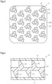
- FIG. 2 is a perspective view showing a second surface of a middle member of the first embodiment.
- FIG. 3 is a plan view showing the second surface of the middle member of the first embodiment.
- FIG. 4 is a cross-sectional view schematically showing a superposition interior component according to a second embodiment.
- FIG. 5 is a cross-sectional view schematically showing a superposition interior component according to a third embodiment.
- FIG. 6 is a cross-sectional view schematically showing a superposition interior component according to a fourth embodiment.
- FIGS. 7 A and 7 B are cross-sectional views schematically showing a superposition interior component according to a fifth embodiment.
- FIG. 8 is a perspective view showing a second surface of a middle member of a sixth embodiment.
- FIG. 9 is a plan view showing the second surface of the middle member of the sixth embodiment.
- FIGS. 10 A and 10 B are cross-sectional views schematically showing a superposition interior component according to the sixth embodiment.
- FIG. 11 is a plan view showing a second surface of a middle member of a seventh embodiment.
- FIGS. 12 A and 12 B are cross-sectional views schematically showing a superposition interior component according to the seventh embodiment.
- FIG. 13 is a cross-sectional view showing a molding apparatus for the middle member of the seventh embodiment.
- FIG. 14 is a plan view showing a second surface of a middle member of an eighth embodiment.
- FIGS. 15 A and 15 B are cross-sectional views schematically showing a superposition interior component according to the eighth embodiment.
- FIGS. 16 A to 16 C are cross-sectional views schematically showing a superposition interior component according to a ninth embodiment.
- FIG. 17 is a cross-sectional view showing a middle member of the ninth embodiment.
- FIG. 18 is a perspective view showing a second surface of a middle member of a tenth embodiment.
- FIG. 19 is a plan view showing the second surface of the middle member of the tenth embodiment.
- FIGS. 20 A to 20 C are cross-sectional views schematically showing a superposition interior component of the middle member of the tenth embodiment.
- FIGS. 1 to 3 A first embodiment will now be described with reference to FIGS. 1 to 3 .
- a superposition interior component (hereinafter, referred to as an interior component 10 ), which is a door rim for an automobile, includes a base 11 , an outer layer member 12 , which is a thin plate covering the base 11 , and a middle member 13 , which is made of a soft plastic and disposed between the base 11 and the outer layer member 12 .
- the base 11 , the middle member 13 , and the outer layer member 12 are stacked together to form the interior component 10 .
- the base 11 is made of a hard plastic such as polypropylene.
- the outer layer member 12 is made of a soft plastic such as soft polyvinyl chloride.
- the middle member 13 is made of a soft plastic such as soft polyvinyl chloride.
- the middle member 13 includes a plate-shaped body 20 , tapered first protrusions 21 , and tapered second protrusions 22 , which are molded integrally.
- the first protrusions 21 protrude from a first surface 20 a of the body 20 , which faces the base 11 .
- the second protrusions 22 protrude from a second surface 20 b of the body 20 , which faces the outer layer member 12 .
- the body 20 of the present embodiment has a uniform thickness, so that the first surface 20 a and the second surface 20 b are parallel with each other.
- the first protrusions 21 are shorter and greater in the cross-sectional size than the second protrusions 22 .
- the second protrusions 22 are each a quadrangular pyramid with all corners rounded.
- first protrusions 21 are each a quadrangular pyramid with all corners rounded, like the second protrusions 22 .
- the protruding direction of the first protrusions 21 and the second protrusions 22 are inclined in relation to the body 20 .
- the protruding direction of the first protrusions 21 is inclined by a predetermined angle ⁇ in relation to a line O normal to the first surface 20 a .
- the protruding direction of the second protrusions 22 is inclined by the predetermined angle ⁇ in relation to a line O normal to the second surface 20 b of the body 20 .
- the second protrusions 22 include sets of three second protrusions 22 located close to one another.
- the proximal portions of the three second protrusions 22 in each set are arranged at positions corresponding to the apexes of a regular triangle. These three second protrusions 22 project in different directions and are separated from one another.
- the arrangement pattern of the first protrusions 21 is the same as the above-described arrangement pattern of the second protrusions 22 .
- the present embodiment has the following advantages.
- the superposition interior component 10 includes the base 11 , the outer layer member 12 , which covers the base 11 , and the middle member 13 , which is made of a soft plastic and disposed between the base 11 and the outer layer member 12 .
- the superposition interior component 10 is formed by stacking the base 11 , the middle member 13 , and the outer layer member 12 together.
- the middle member 13 includes the plate-shaped body 20 , the first protrusions 21 , and the second protrusions 22 .
- the first protrusions 21 protrude from the first surface 20 a of the body 20 , which faces the base 11 .
- the second protrusions 22 protrude from the second surface 20 b of the body 20 , which faces the outer layer member 12 .
- the second protrusions 22 which protrude from the body 20 of the middle member 13 , are deformed to bend while being in contact with the outer layer member 12 .
- the first protrusions 21 which protrude from the body 20 , are deformed to bend while being in contact with the base 11 .
- the interior component thus provides the user with a tactile impression similar to that of an interior component having a foamed material, such as urethane foam, embedded therein.
- the outer layer member 12 does not need to include protrusions, it is possible to avoid drawbacks due to molding defects of the outer layer member 12 caused by molding protrusions.
- the thickness of the outer layer member 12 can be reduced, it is possible to avoid a hard tactile impression when the outer layer member 12 is depressed.
- the present embodiment increases the depressible amount and improves the aesthetic appeal of the superposition interior component 10 .
- the protruding direction of the first protrusions 21 and the second protrusions 22 are inclined in relation to the body 20 .
- the present embodiment reliably provides the user with a tactile impression similar to that of an interior component having a foamed material, such as urethane foam, embedded therein.
- the body 20 , the first protrusions 21 , and the second protrusions 22 are molded integrally.
- the body 20 , the first protrusions 21 , and the second protrusions 22 , which form the middle member 13 are molded integrally, the existence of the middle member 13 does not increase the number of components. This prevents the structure of the interior component 10 from being complicated.
- the middle member 13 is made of a soft plastic. This reduces the molding time as compared to a case in which a foamed material, such as urethane foam, is used.
- a second embodiment will now be described with reference to FIG. 4 . Differences from the first embodiment will mainly be discussed. Thus, the same or corresponding components as those in the first embodiment are given the same reference numerals, and detailed explanations are omitted.
- first protrusions 21 and second protrusions 22 have the same length.
- the first protrusions 21 and the second protrusions 22 have the same cross-sectional size.
- the superposition interior component 10 according to the above-described present embodiment has the advantages (1) to (4) of the first embodiment.
- a third embodiment will now be described with reference to FIG. 5 . Differences from the first embodiment will mainly be discussed. Thus, the same or corresponding components as those in the first embodiment are given the same reference numerals, and detailed explanations are omitted.
- a middle member 13 includes a first member 14 and a second member 15 , which are provided separately.
- the first member 14 includes a plate-shaped body segment 20 A and first protrusions 21 , which protrude from a first surface 20 a of the body segment 20 A.
- the second member 15 includes a plate-shaped body segment 20 B and second protrusions 22 , which protrude from a second surface 20 b of the body segment 20 B.
- the surface of the body segment 20 A of the first member 14 opposite from the first surface 20 a and the surface of the body segment 20 B of the second member 15 opposite from the second surface 20 b are in contact with each other.
- the superposition interior component 10 has the advantages (1), (2), and (4) of the first embodiment.
- a fourth embodiment will now be described with reference to FIG. 6 . Differences from the second embodiment will mainly be discussed. Thus, the same or corresponding components as those in the second embodiment are given the same reference numerals, and detailed explanations are omitted.
- the protruding direction of first protrusions 21 and the protruding direction of second protrusions 22 are both perpendicular to the body 20 .
- the superposition interior component according to the above-described present embodiment has the advantages (1), (3), and (4) of the first embodiment.
- a first member 14 is disposed between a base 11 and a middle member 13 .
- a second member 15 is disposed between an outer layer member 12 and the middle member 13 .
- the first member 14 and the second member 15 respectively have the same structures as the first member 14 and the second member 15 described in the third embodiment. That is, the first member 14 includes a plate-shaped body segment 20 A and protrusions 21 , which protrude from a first surface 20 a of the body segment 20 A, and the first surface 20 a faces the base 11 .
- the second member 15 includes a plate-shaped body segment 20 B and protrusions 22 , which protrude from a second surface 20 b of the body segment 20 B, and the second surface 20 b faces the outer layer member 12 .
- the distal ends of the first protrusions 21 of the middle member 13 are in contact with the body segment 20 A of the first member 14 .
- the distal ends of the second protrusions 22 of the middle member 13 are in contact with the body segment 20 B of the second member 15 .
- the distal ends of the protrusions 21 of the first member 14 are in contact with the base 11 .
- the distal ends of the protrusions 22 of the second member 15 are in contact with the outer layer member 12 .
- the protrusions 22 of the second member 15 are deformed to bend while being in contact with the outer layer member 12 .
- the second member 15 which is displaced toward the base 11 , depresses the middle member 13 , so that the second protrusions 22 and the first protrusions 21 of the middle member 13 are deformed to bend.
- the middle member 13 which is displaced toward the base 11 , depresses the first member 14 , so that the protrusions 21 of the first member 14 are deformed to bend while being in contact with the base 11 .
- the superposition interior component according to the above-described present embodiment has an advantage (5) in addition to the advantages (1) to (4) of the first embodiment.
- the present embodiment further increases the depressible amount of the superposition interior component 10 .
- a middle member 13 includes multiple pairs of a first protrusion 21 and a second protrusion 22 .
- a proximal end 21 a of the first protrusion 21 and a proximal end 22 a of the second protrusion 22 of each pair are disposed on the opposite sides of a body 20 . More specifically, the first protrusion 21 and the second protrusion 22 of each pair are symmetrical with respect to an imaginary plane parallel with the body 20 .
- the body 20 includes accommodation holes 23 .
- Each accommodation hole 23 extends from the proximal ends 21 a and 22 a of the corresponding pair of the first protrusion 21 and the second protrusion 22 .
- the protrusions 21 , 22 are inclined in relation to the body 20 so as to approach the adjacent accommodation holes 23 .
- each accommodation hole 23 accommodates a first protrusion 21 and a second protrusion 22 , which have been deformed to bend.
- the sum of the maximum value d 1 of the cross-sectional size of each first protrusion 21 and the maximum value d 2 of the cross-sectional size of each second protrusion 22 is set to be less than or equal to the thickness T of the body 20 (d 1 +d 2 ⁇ T).
- the superposition interior component according to the above-described present embodiment has the following advantage (6) in addition to the advantages (1) to (4) of the first embodiment.
- the present embodiment further increases the depressible amount of the superposition interior component 10 .
- a body 20 includes first accommodation holes 24 for accommodating first protrusions 21 and second accommodation holes 25 for accommodating second protrusions 22 .
- Each first accommodation hole 24 and each second accommodation hole 25 extend in opposite directions from the proximal ends 21 a and 22 a of the corresponding first protrusion 21 and the corresponding second protrusion 22 . More specifically, each first protrusion 21 is inclined in relation to the body 20 so as to approach the corresponding first accommodation hole 24 . Also, each second protrusion 22 is inclined in relation to the body 20 so as to approach the corresponding second accommodation hole 25 .
- the second protrusions 22 which protrude from the body 20 of the middle member 13 , are deformed to bend while being in contact with the outer layer member 12 as shown in FIG. 12 B .
- the first protrusions 21 which protrude from the body 20 , are deformed to bend while being in contact with the base 11 .
- the first protrusion 21 and the second protrusion 22 are accommodated in the different accommodation holes 24 , 25 .
- the superposition interior component according to the above-described present embodiment has the following advantage (7) in addition to the advantages (1) to (4) of the first embodiment.
- the above-described configuration aligns the protruding direction of each first protrusion 21 and the protruding direction of the corresponding second protrusion 22 with each other as shown in FIG. 12 A . Accordingly, when the middle member 13 is molded using a first mold half 50 and a second mold half 60 as shown in FIG. 13 , a projection 51 of the first mold half 50 forms a surface of the first protrusion 21 that faces the second accommodation hole 25 , the second accommodation hole 25 , and a surface of the second protrusion 22 that faces the second accommodation hole 25 .
- a projection 61 of the second mold half 60 forms a surface of the first protrusion 21 that faces the first accommodation hole 24 , the first accommodation hole 24 , and a surface of the second protrusion 22 that faces the first accommodation hole 24 .
- the use of the first mold half 50 and the second mold half 60 suppresses the formation of undercuts and allows the middle member 13 to be molded easily.
- a body 20 includes multiple accommodation holes 26 having a regular hexagonal shape in a plan view.
- the accommodation holes 26 are arranged such that the adjacent sides of every adjacent two of the accommodation holes 26 are parallel with each other, and distances between the accommodation holes 26 are constant.
- a pair of a first protrusion 21 and a second protrusion 22 is provided between every adjacent two of the accommodation holes 26 in the body 20 .
- the proximal ends 21 a and 22 a of the first protrusion 21 and the second protrusion 22 are provided with a section of the body 20 in between.
- the first protrusion 21 and the second protrusion 22 of each pair are respectively accommodated in adjacent two of the accommodation holes 26 .
- a pair of a first protrusion 21 and a second protrusion 22 corresponds to each side of each accommodation hole 26 . That is, six pairs of a first protrusion 21 and a second protrusion 22 are provided around each accommodation hole 26 .
- three second protrusions 22 are provided on three of the six sides (every other side of the six sides) of each accommodation hole 26 . These three second protrusions 22 are inclined in relation to the body 20 so as to approach the accommodation hole 26 , and are accommodated in the accommodation hole 26 .
- first protrusions 21 are provided on the three of the six sides of each accommodation hole 26 on which the second protrusions 22 are not provided. These three first protrusions 21 are inclined in relation to the body 20 so as to approach the accommodation hole 26 , and are accommodated in the accommodation hole 26 .
- the superposition interior component according to the above-described present embodiment has the following advantage (8) in addition to the advantages (1) to (4) of the first embodiment and the advantage (7) of the seventh embodiment.
- the distances between the accommodation holes 26 are constant.
- the thickness of the mold for forming the middle member 13 is prevented from being reduced locally. This reliably ensures the strength of the mold.
- a middle member 13 is held between a base 11 and an outer layer member 12 .
- the body 20 is shaped as a hollow plate.
- the body 20 is cylindrical when in a natural state, in which the body 20 is not held between the base 11 and the outer layer member 12 and not receiving an external force.
- the body 20 includes protrusions 21 , 22 on the outer circumferential surface.
- the protrusions 21 , 22 are separated from each other in the circumferential direction and the axial direction of the body 20 .
- the superposition interior component according to the above-described present embodiment has the following advantage (9) in addition to the advantages (1) to (4) of the first embodiment.
- the body 20 Since the body 20 is shaped as a hollow plate, the body 20 itself can be deformed in the thickness direction in addition to the first protrusions 21 and the second protrusions 22 . Thus, the present embodiment further increases the depressible amount of the superposition interior component 10 .
- a body 20 includes plate-shaped first body segments 20 A and plate-shaped second body segments 20 B.
- the first body segments 20 A are arranged in a plane in the body 20 while being separated from each other, and the second body segments 20 B are arranged in a plane in the body 20 while being separated from each other.
- Each first body segment 20 A substantially has the shape of a regular triangle in a plan view.
- Each second body segment 20 B substantially has the shape of a regular hexagon in a plan view.
- the second body segment 20 B are each located among the corresponding first body segments 20 A and are closer to the outer layer member 12 than the first body segments 20 A.
- a middle member 13 includes coupling portions 27 , which couple the first body segments 20 A and the second body segments 20 B to each other.
- the coupling portions 27 extend outward and toward the base 11 from three (every other apex) of the six apexes of each second body segment 20 B. Two of the first body segments 20 A are disposed between every adjacent two of the coupling portions 27 . These two first body segments 20 A are coupled to the coupling portions 27 with apexes opposed to each other.
- a lightening portion 28 is formed between every adjacent two of the coupling portions 27 and between the two first body segments 20 A located between these coupling portions 27 .
- the coupling portions 27 are thinner and thus weaker than the first body segments 20 A, the second body segments 20 B, the first protrusions 21 , and the second protrusions 22 .
- each first body segment 20 A includes a first protrusion 21 on a first surface 20 a , which faces the base 11 , and second protrusion 22 on a second surface 20 b , which faces the outer layer member 12 .
- Each second body segment 20 B includes a first protrusion 21 on a first surface 20 a , which faces the base 11 , and second protrusion 22 on a second surface 20 b , which faces the outer layer member 12 .
- the second protrusions 22 which protrude from the second body segments 20 B of the middle member 13 , are brought into contact with the outer layer member 12 as shown in FIG. 20 B .
- the coupling portions 27 are deformed to bend prior to the first body segments 20 A, the second body segments 20 B, the first protrusions 21 , and the second protrusions 22 .
- the second body segments 20 B are displaced to the same position as the first body segments 20 A.
- the second protrusions 22 of the first body segments 20 A are brought into contact with the outer layer member 12
- the first protrusions 21 of the second body segments 20 B are brought into contact with the base 11 .
- the superposition interior component according to the above-described present embodiment has the following advantage (10) in addition to the advantages (1) to (4) of the first embodiment.
- the coupling portions 27 can be deformed in the thickness direction in addition to the first protrusions 21 and the second protrusions 22 .
- the present embodiment further increases the depressible amount of the superposition interior component 10 .
- the material of the outer layer member 12 may be changed to other materials.
- the material may be a woven fabric or a soft plastic other than soft polyvinyl chloride.
- the soft plastic includes as an elastomer (Shore hardness in a range approximately from 30 D to 40 D).
- the material of the middle member 13 may be changed to other materials.
- the material may be a soft plastic other than soft polyvinyl chloride.
- the soft plastic includes a polyester-based elastomer.
- the arrangement pattern of the first protrusions 21 and the second protrusions 22 may be changed.
- first protrusions 21 and the second protrusions 22 may be changed.
- first protrusions 21 may be longer and have a smaller cross-sectional size than the second protrusions 22 .
- the inclination angle of the protruding direction of the first protrusions 21 in relation to the normal line O may be different from the inclination angle of the protruding direction of the second protrusions 22 in relation to the normal line O.
- each first protrusion is in contact with the base 11
- the distal end of each second protrusion is in contact with the outer layer member 12
- the present invention is not limited to this.
- a structure may be employed in which the distal ends of some or all of the first protrusions are not in contact with a base.
- a structure may be employed in which some or all of the second protrusions are not in contact with an outer layer member.
- the sixth to eighth embodiments describe structures in which the protrusions 21 , 22 are entirely accommodated in the accommodation holes 23 , 24 , 25 , 26 .
- the protrusions 21 , 22 may be partly accommodated in accommodation holes.
- the shape of the accommodation holes 26 in the eighth embodiment is not limited to a regular hexagon in a plan view, but may be a quadrilateral in a front view.
- the tenth embodiment describes the structure in which the coupling portions 27 are weaker than the first body segments 20 A, the second body segments 20 B, the first protrusions 21 , and the second protrusions 22 .
- the present invention is not limited to this.
- a structure may be employed in which the first protrusions 21 and the second protrusions 22 are deformed prior to the coupling portions 27 .
- the superposition interior components according to the present invention are not limited to door trims, but may be used for other interior components of a vehicle, such as an instrument panel and a glove compartment.
Landscapes
- Engineering & Computer Science (AREA)
- Mechanical Engineering (AREA)
- Textile Engineering (AREA)
- Vehicle Interior And Exterior Ornaments, Soundproofing, And Insulation (AREA)
- Laminated Bodies (AREA)
Applications Claiming Priority (3)
| Application Number | Priority Date | Filing Date | Title |
|---|---|---|---|
| JP2019065860 | 2019-03-29 | ||
| JP2019-065860 | 2019-03-29 | ||
| PCT/JP2019/043666 WO2020202626A1 (fr) | 2019-03-29 | 2019-11-07 | Composant à intérieur en superposition |
Publications (2)
| Publication Number | Publication Date |
|---|---|
| US20220152972A1 US20220152972A1 (en) | 2022-05-19 |
| US11794442B2 true US11794442B2 (en) | 2023-10-24 |
Family
ID=72667827
Family Applications (1)
| Application Number | Title | Priority Date | Filing Date |
|---|---|---|---|
| US17/598,898 Active 2040-02-09 US11794442B2 (en) | 2019-03-29 | 2019-11-07 | Superposition interior component |
Country Status (5)
| Country | Link |
|---|---|
| US (1) | US11794442B2 (fr) |
| EP (1) | EP3950296A4 (fr) |
| JP (1) | JP7111888B2 (fr) |
| CN (1) | CN113631361B (fr) |
| WO (1) | WO2020202626A1 (fr) |
Families Citing this family (3)
| Publication number | Priority date | Publication date | Assignee | Title |
|---|---|---|---|---|
| US11981268B2 (en) * | 2021-10-13 | 2024-05-14 | GM Global Technology Operations LLC | Energy absorbing material for a vehicle |
| JP7518054B2 (ja) * | 2021-10-22 | 2024-07-17 | 豊田鉄工株式会社 | 重ね合わせ内装部品及び重ね合わせ内装部品用のクッション部材 |
| JP7544946B1 (ja) | 2023-11-07 | 2024-09-03 | 豊田鉄工株式会社 | 重ね合わせ複合部品の製造方法 |
Citations (3)
| Publication number | Priority date | Publication date | Assignee | Title |
|---|---|---|---|---|
| JP2010143553A (ja) | 2008-12-22 | 2010-07-01 | Mitsubishi Motors Corp | 自動車用ドア |
| WO2013132677A1 (fr) | 2012-03-07 | 2013-09-12 | 豊田鉄工株式会社 | Élément composite superposé |
| US20160101743A1 (en) | 2013-05-15 | 2016-04-14 | Toyoda Iron Works Co., Ltd | Laminated Composite Interior Part |
Family Cites Families (10)
| Publication number | Priority date | Publication date | Assignee | Title |
|---|---|---|---|---|
| JP2000177468A (ja) * | 1998-12-15 | 2000-06-27 | T S Tec Kk | 車両用内装部品の緩衝構造 |
| CN2592375Y (zh) * | 2002-10-28 | 2003-12-17 | 陈猛 | 中间层有凹凸板的金属复合装饰板材 |
| JP5299055B2 (ja) * | 2009-04-21 | 2013-09-25 | 日産自動車株式会社 | 車両用内装部品 |
| WO2014077074A1 (fr) * | 2012-11-16 | 2014-05-22 | 日産自動車株式会社 | Matériau de revêtement |
| JP5851387B2 (ja) * | 2012-12-06 | 2016-02-03 | 豊田鉄工株式会社 | 重ね合わせ複合部品 |
| JP6046824B2 (ja) * | 2013-09-13 | 2016-12-21 | 豊田鉄工株式会社 | 重ね合わせ複合内装部品 |
| JP6131233B2 (ja) * | 2014-10-24 | 2017-05-17 | 豊田鉄工株式会社 | 重ね合わせ複合内装部品 |
| JP6339535B2 (ja) * | 2015-07-28 | 2018-06-06 | 豊田鉄工株式会社 | 重ね合わせ複合内装部品 |
| JP2017171158A (ja) * | 2016-03-24 | 2017-09-28 | 豊田鉄工株式会社 | 重ね合わせ複合内装部品 |
| JP2018058490A (ja) * | 2016-10-05 | 2018-04-12 | 豊田鉄工株式会社 | 車両用内装部品 |
-
2019
- 2019-11-07 EP EP19923441.0A patent/EP3950296A4/fr active Pending
- 2019-11-07 CN CN201980094722.9A patent/CN113631361B/zh active Active
- 2019-11-07 JP JP2021511093A patent/JP7111888B2/ja active Active
- 2019-11-07 US US17/598,898 patent/US11794442B2/en active Active
- 2019-11-07 WO PCT/JP2019/043666 patent/WO2020202626A1/fr unknown
Patent Citations (5)
| Publication number | Priority date | Publication date | Assignee | Title |
|---|---|---|---|---|
| JP2010143553A (ja) | 2008-12-22 | 2010-07-01 | Mitsubishi Motors Corp | 自動車用ドア |
| WO2013132677A1 (fr) | 2012-03-07 | 2013-09-12 | 豊田鉄工株式会社 | Élément composite superposé |
| US20150072105A1 (en) | 2012-03-07 | 2015-03-12 | Toyoda Iron Works Co., Ltd. | Superimposed composite interior component |
| US20170165939A1 (en) | 2012-03-07 | 2017-06-15 | Toyoda Iron Works Co., Ltd. | Superimposed composite interior component |
| US20160101743A1 (en) | 2013-05-15 | 2016-04-14 | Toyoda Iron Works Co., Ltd | Laminated Composite Interior Part |
Non-Patent Citations (1)
| Title |
|---|
| Extended European Search Report dated Nov. 28, 2022 issued in European Application No. 19923441.0, 7pages. |
Also Published As
| Publication number | Publication date |
|---|---|
| JP7111888B2 (ja) | 2022-08-02 |
| JPWO2020202626A1 (fr) | 2020-10-08 |
| EP3950296A1 (fr) | 2022-02-09 |
| WO2020202626A1 (fr) | 2020-10-08 |
| CN113631361B (zh) | 2023-08-29 |
| US20220152972A1 (en) | 2022-05-19 |
| EP3950296A4 (fr) | 2022-12-28 |
| CN113631361A (zh) | 2021-11-09 |
Similar Documents
| Publication | Publication Date | Title |
|---|---|---|
| US11794442B2 (en) | Superposition interior component | |
| US9815418B2 (en) | Laminated composite interior part | |
| EP3045305B1 (fr) | Composant intérieur composite multicouche | |
| EP3330133B1 (fr) | Composant d'intérieur composite empilé | |
| US20110287220A1 (en) | Surface structure of article | |
| US9573341B2 (en) | Multi-layer composite part | |
| EP3210770B1 (fr) | Partie intérieure de composite empilé | |
| US20150290904A1 (en) | Stacked composite component | |
| JP7041640B2 (ja) | 表皮係止用クリップ | |
| JP5950814B2 (ja) | 重ね合わせ複合部品 | |
| JP2000193090A (ja) | 防水パッキン | |
| EP3150441B1 (fr) | Composant intérieur composite à encastrement | |
| JP2022016782A (ja) | 重ね合わせ内装部品及び重ね合わせ内装部品用のクッション部材 | |
| JP2017171158A (ja) | 重ね合わせ複合内装部品 | |
| US11002357B2 (en) | Shift device | |
| JP7544946B1 (ja) | 重ね合わせ複合部品の製造方法 | |
| JP7518054B2 (ja) | 重ね合わせ内装部品及び重ね合わせ内装部品用のクッション部材 | |
| JP7541203B1 (ja) | 金型 |
Legal Events
| Date | Code | Title | Description |
|---|---|---|---|
| AS | Assignment |
Owner name: TOYODA IRON WORKS CO., LTD., JAPAN Free format text: ASSIGNMENT OF ASSIGNORS INTEREST;ASSIGNORS:YOSHIDA, KENICHI;MIYASHITA, OSAMU;SAKAI, HIDEAKI;AND OTHERS;REEL/FRAME:057616/0333 Effective date: 20210805 |
|
| FEPP | Fee payment procedure |
Free format text: ENTITY STATUS SET TO UNDISCOUNTED (ORIGINAL EVENT CODE: BIG.); ENTITY STATUS OF PATENT OWNER: LARGE ENTITY |
|
| STPP | Information on status: patent application and granting procedure in general |
Free format text: DOCKETED NEW CASE - READY FOR EXAMINATION |
|
| STPP | Information on status: patent application and granting procedure in general |
Free format text: RESPONSE TO NON-FINAL OFFICE ACTION ENTERED AND FORWARDED TO EXAMINER |
|
| STPP | Information on status: patent application and granting procedure in general |
Free format text: ALLOWED -- NOTICE OF ALLOWANCE NOT YET MAILED |
|
| STPP | Information on status: patent application and granting procedure in general |
Free format text: NOTICE OF ALLOWANCE MAILED -- APPLICATION RECEIVED IN OFFICE OF PUBLICATIONS |
|
| STPP | Information on status: patent application and granting procedure in general |
Free format text: PUBLICATIONS -- ISSUE FEE PAYMENT RECEIVED |
|
| STPP | Information on status: patent application and granting procedure in general |
Free format text: PUBLICATIONS -- ISSUE FEE PAYMENT VERIFIED |
|
| STCF | Information on status: patent grant |
Free format text: PATENTED CASE |