US11761899B2 - Inspection method and inspection system for cylindrical honeycomb structure made of ceramics - Google Patents
Inspection method and inspection system for cylindrical honeycomb structure made of ceramics Download PDFInfo
- Publication number
- US11761899B2 US11761899B2 US17/188,123 US202117188123A US11761899B2 US 11761899 B2 US11761899 B2 US 11761899B2 US 202117188123 A US202117188123 A US 202117188123A US 11761899 B2 US11761899 B2 US 11761899B2
- Authority
- US
- United States
- Prior art keywords
- honeycomb structure
- cylindrical honeycomb
- end surface
- line sensor
- sensor camera
- Prior art date
- Legal status (The legal status is an assumption and is not a legal conclusion. Google has not performed a legal analysis and makes no representation as to the accuracy of the status listed.)
- Active, expires
Links
Images


Classifications
-
- G—PHYSICS
- G01—MEASURING; TESTING
- G01N—INVESTIGATING OR ANALYSING MATERIALS BY DETERMINING THEIR CHEMICAL OR PHYSICAL PROPERTIES
- G01N21/00—Investigating or analysing materials by the use of optical means, i.e. using sub-millimetre waves, infrared, visible or ultraviolet light
- G01N21/84—Systems specially adapted for particular applications
- G01N21/88—Investigating the presence of flaws or contamination
- G01N21/8851—Scan or image signal processing specially adapted therefor, e.g. for scan signal adjustment, for detecting different kinds of defects, for compensating for structures, markings, edges
-
- G—PHYSICS
- G01—MEASURING; TESTING
- G01N—INVESTIGATING OR ANALYSING MATERIALS BY DETERMINING THEIR CHEMICAL OR PHYSICAL PROPERTIES
- G01N21/00—Investigating or analysing materials by the use of optical means, i.e. using sub-millimetre waves, infrared, visible or ultraviolet light
- G01N21/84—Systems specially adapted for particular applications
- G01N21/88—Investigating the presence of flaws or contamination
- G01N21/95—Investigating the presence of flaws or contamination characterised by the material or shape of the object to be examined
- G01N21/956—Inspecting patterns on the surface of objects
- G01N21/95692—Patterns showing hole parts, e.g. honeycomb filtering structures
-
- G—PHYSICS
- G01—MEASURING; TESTING
- G01N—INVESTIGATING OR ANALYSING MATERIALS BY DETERMINING THEIR CHEMICAL OR PHYSICAL PROPERTIES
- G01N21/00—Investigating or analysing materials by the use of optical means, i.e. using sub-millimetre waves, infrared, visible or ultraviolet light
- G01N21/01—Arrangements or apparatus for facilitating the optical investigation
-
- G—PHYSICS
- G01—MEASURING; TESTING
- G01N—INVESTIGATING OR ANALYSING MATERIALS BY DETERMINING THEIR CHEMICAL OR PHYSICAL PROPERTIES
- G01N21/00—Investigating or analysing materials by the use of optical means, i.e. using sub-millimetre waves, infrared, visible or ultraviolet light
- G01N21/84—Systems specially adapted for particular applications
- G01N21/88—Investigating the presence of flaws or contamination
- G01N21/89—Investigating the presence of flaws or contamination in moving material, e.g. running paper or textiles
- G01N21/8914—Investigating the presence of flaws or contamination in moving material, e.g. running paper or textiles characterised by the material examined
-
- G—PHYSICS
- G01—MEASURING; TESTING
- G01N—INVESTIGATING OR ANALYSING MATERIALS BY DETERMINING THEIR CHEMICAL OR PHYSICAL PROPERTIES
- G01N21/00—Investigating or analysing materials by the use of optical means, i.e. using sub-millimetre waves, infrared, visible or ultraviolet light
- G01N21/84—Systems specially adapted for particular applications
- G01N21/88—Investigating the presence of flaws or contamination
- G01N21/95—Investigating the presence of flaws or contamination characterised by the material or shape of the object to be examined
- G01N21/952—Inspecting the exterior surface of cylindrical bodies or wires
-
- G—PHYSICS
- G06—COMPUTING OR CALCULATING; COUNTING
- G06T—IMAGE DATA PROCESSING OR GENERATION, IN GENERAL
- G06T7/00—Image analysis
- G06T7/0002—Inspection of images, e.g. flaw detection
- G06T7/0004—Industrial image inspection
- G06T7/0008—Industrial image inspection checking presence/absence
-
- H—ELECTRICITY
- H04—ELECTRIC COMMUNICATION TECHNIQUE
- H04N—PICTORIAL COMMUNICATION, e.g. TELEVISION
- H04N7/00—Television systems
- H04N7/18—Closed-circuit television [CCTV] systems, i.e. systems in which the video signal is not broadcast
- H04N7/183—Closed-circuit television [CCTV] systems, i.e. systems in which the video signal is not broadcast for receiving images from a single remote source
-
- G—PHYSICS
- G01—MEASURING; TESTING
- G01N—INVESTIGATING OR ANALYSING MATERIALS BY DETERMINING THEIR CHEMICAL OR PHYSICAL PROPERTIES
- G01N21/00—Investigating or analysing materials by the use of optical means, i.e. using sub-millimetre waves, infrared, visible or ultraviolet light
- G01N21/01—Arrangements or apparatus for facilitating the optical investigation
- G01N2021/0106—General arrangement of respective parts
- G01N2021/0112—Apparatus in one mechanical, optical or electronic block
-
- G—PHYSICS
- G06—COMPUTING OR CALCULATING; COUNTING
- G06T—IMAGE DATA PROCESSING OR GENERATION, IN GENERAL
- G06T2207/00—Indexing scheme for image analysis or image enhancement
- G06T2207/30—Subject of image; Context of image processing
- G06T2207/30108—Industrial image inspection
Definitions
- the present invention relates to an inspection method and an inspection system for inspecting a cylindrical honeycomb structure made of ceramics.
- Cylindrical honeycomb structures made of ceramics which are excellent in heat resistance, thermal shock resistance, and oxidation resistance, have been widely used as a filter for collecting particulate matter contained in the exhaust gas from an internal combustion engine, a boiler, etc. and as a catalyst carrier for exhaust gas purification catalysts.
- a cylindrical honeycomb structure made of ceramics comprises a side surface, and a plurality of partition walls disposed on the inner peripheral side of the side surface, the partition walls partitioning a plurality of cells extending in the height direction from a first end surface to a second end surface.
- the cylindrical honeycomb structure made of ceramics can be manufactured, for example, through a step of kneading a powder of ceramic raw material as the constituent material with an organic binder, water, etc. to and the like to obtain a clay-like green body and forming the green body into a cylindrical honeycomb formed body with an extrusion molding method, and a step of firing the cylindrical honeycomb formed body.
- defects such as cracks or foreign substances adhering to the side surface of the cylindrical honeycomb structure may occur.
- the occurrence of cracks and the adhesion of foreign substances may lead to a decrease in the strength of the cylindrical honeycomb structure, a decrease in filtration performance when the cylindrical honeycomb structure is used as a filter, and a decrease in exhaust gas purification performance when it is used as a catalyst carrier. Therefore, it is necessary to inspect the presence or absence of defects on the side surface of the cylindrical honeycomb structure.
- Patent Literature 1 discloses a method for surface inspection that can determine the presence or absence of cracks formed on the side surface of the honeycomb structure with a simple method comprising imaging with two illumination lights with different irradiation directions and wavelength bands, and comparing two images for determination which are generated based on the imaging result.
- Patent Literature 1 WO 2017/061318
- Patent Literature 1 by imaging the side surface of a honeycomb structure using two illumination lights with different irradiation directions and wavelength bands, and comparing the two images for determination which are generated based on the imaging result, it is possible to distinguish between cracks and swells (surface undulations) that do not cause quality problems, and prevent excessive detection.
- the technique of Patent Literature 1 does not sufficiently deal withs fine cracks. Therefore, it is desirable to provide an inspection method capable of quickly inspecting the presence or absence of fine defects (for example, cracks having a width of about 5 to 25 ⁇ m) on the side surface of the cylindrical honeycomb structure made of ceramics.
- an object is to provide an inspection method capable of quickly inspecting the presence or absence of fine defects on the side surface of a cylindrical honeycomb structure made of ceramics. Further, according to another embodiment, an object is to provide an inspection system suitable for carrying out such an inspection method.
- the outer shape of a cylindrical honeycomb structure may be not a mathematically perfect cylinder, and dimensional errors may occur. Therefore, when the entire side surface is inspected with a line sensor camera while rotating the cylindrical honeycomb structure, the distance between the camera and the cylindrical honeycomb structure fluctuates slightly. If the fluctuation of the distance exceeds the depth of field, a focused image cannot be obtained. Therefore, it is necessary to increase the depth of field in order to cope with the dimensional errors. However, if the F value (aperture value) is increased in order to increase the depth of field, there is a problem that the diameter of the Airy disk becomes large and the inspection accuracy decreases.
- An inspection method for a cylindrical honeycomb structure comprising:
- the inspection method for a cylindrical honeycomb structure according to [1] or [2], wherein the step of determining the presence or absence of defects on the side surface based on the inspection image comprises determining presence or absence of cracks having a width of 5 to 25 ⁇ m.
- the inspection method for a cylindrical honeycomb structure according to any one of [1] to [3], wherein the rotation stage is capable of moving in X, Y, and Z directions, and the step of placing the cylindrical honeycomb structure on the rotation stage comprises:
- the inspection method for a cylindrical honeycomb structure according to any one of [1] to [6], wherein the step of repeatedly capturing the reflected light from the side surface with the line sensor camera is carried out while rotating the cylindrical honeycomb structure at an average peripheral speed of 100 to 1000 mm/sec.
- the present invention it is possible to quickly inspect the presence or absence of fine defects (for example, cracks having a width of about 5 to 25 ⁇ m) on the side surface of a cylindrical honeycomb structure made of ceramics.
- fine defects for example, cracks having a width of about 5 to 25 ⁇ m
- FIG. 1 is a perspective view schematically showing a wall-through type pillar-shaped honeycomb structure.
- FIG. 2 is a schematic cross-sectional view of a wall-through type pillar-shaped honeycomb structure observed in a cross-section parallel to the direction in which the cells extend.
- FIG. 3 is a perspective view schematically showing a wall-flow type pillar-shaped honeycomb structure.
- FIG. 4 is a schematic cross-sectional view of a wall-flow type pillar-shaped honeycomb structure observed in a cross-section parallel to the direction in which the cells extend.
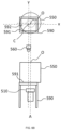
- FIG. 5 is a schematic side view for illustrating a configuration of an inspection system according to one embodiment of the present invention.
- FIG. 6 A is a schematic view showing a state when the position of the center of gravity O of the first end surface is measured based on the result of capturing the first end surface by the area camera.
- FIG. 6 B is a schematic view showing a state when the axis of rotation A of the rotation stage moves directly below the position of the center of gravity O of the first end surface based on the measured position of the center of gravity O of the first end surface.
- FIG. 6 C is a schematic view showing a state when the rotation stage rises relative to the cylindrical honeycomb structure and lifts the cylindrical honeycomb structure from the side of the second end surface.
- FIG. 6 D is a schematic view showing a state when the cylindrical honeycomb structure lifted by the rotation stage is moved to a predetermined inspection center C.
- FIG. 7 is a schematic view of a micrograph of a fine crack having a width of about 10 ⁇ m.
- the inspection target is a cylindrical honeycomb structure made of ceramics, which comprises a first end surface, a second end surface, and a side surface.
- ceramics constituting the cylindrical honeycomb structure though not limited to, but preferably, ceramic comprising at least one selected from the group consisting of cordierite, mullite, zircon, aluminum titanate, silicon carbide, silicon-silicon carbide composite, silicon nitride, zirconia, spinel, indialite, sapphirine, corundum, and titania may be mentioned for example.
- one type may be contained alone, or two or more types may be contained at the same time.
- FIGS. 1 and 2 illustrate a schematic perspective view and a cross-sectional view of a cylindrical honeycomb structure ( 100 ) that can be used as a wall through type exhaust gas filter and/or catalyst carrier for automobiles, respectively.
- the cylindrical honeycomb structure ( 100 ) comprises an outer peripheral side wall ( 102 ), and partition walls ( 112 ) disposed on an inner peripheral side of the outer peripheral side wall ( 102 ), the partition walls ( 112 ) partitioning a plurality of cells ( 108 ) forming flow paths for fluid from a first end surface ( 104 ) to a second end surface ( 106 ).
- the outer surface of the outer peripheral side wall ( 102 ) forms the side surface ( 103 ) of the cylindrical honeycomb structure ( 100 ).
- both ends of each cell ( 108 ) are open, and an exhaust gas flowing into each cell ( 108 ) from the first end surface ( 104 ) is purified while passing through the cell, and flows out of the second end surface ( 106 ).
- the first end surface ( 104 ) is on the upstream side of the exhaust gas and the second end surface ( 106 ) is on the downstream side of the exhaust gas, but this difference between the first end surface and the second end surface is for the sake of convenience, and the second end surface ( 106 ) may be on the upstream side of the exhaust gas, and the first end surface ( 104 ) may be on the downstream side of the exhaust gas.
- FIGS. 3 and 4 illustrate a schematic perspective view and a cross-sectional view of a cylindrical honeycomb structure ( 200 ) that can be used as a wall-flow type exhaust gas filter and/or catalyst carrier for automobiles, respectively.
- the cylindrical honeycomb structure ( 200 ) comprises an outer peripheral side wall ( 202 ) and partition walls ( 212 ) disposed on an inner peripheral side of the outer peripheral side wall ( 202 ), the partition walls ( 212 ) partitioning a plurality of cells ( 208 a , 208 b ) forming flow paths for fluid from a first end surface ( 204 ) to a second end surface ( 206 ).
- the outer surface of the outer peripheral side wall ( 202 ) forms the side surface ( 203 ) of the cylindrical honeycomb structure ( 200 ).
- the plurality of cells ( 208 a , 208 b ) can be classified into a plurality of first cells ( 208 a ) extending from the first end surface ( 204 ) to the second end surface ( 206 ), opening on the first end surface ( 204 ) and being sealed on the second end surface ( 206 ), and a plurality of second cells ( 208 b ) disposed on the inner peripheral side from the outer peripheral side wall ( 202 ), extending from the first end surface ( 204 ) to the second end surface ( 206 ), being sealed on the first end surface ( 204 ) and opening on the second end surface ( 206 ).
- the first cells ( 208 a ) and the second cells ( 208 b ) are alternately arranged adjacent to each other with the partition walls ( 212 ) interposed therebetween.
- the exhaust gas When an exhaust gas containing particulate matter such as soot is supplied to the first end surface ( 204 ) on the upstream side of the cylindrical honeycomb structure ( 200 ), the exhaust gas is introduced into the first cells ( 208 a ) and proceeds downstream in the first cells ( 208 a ). Because the first cells ( 208 a ) are sealed on the second end surface ( 206 ) on the downstream side, the exhaust gas passes through the porous partition walls ( 212 ) that partition the first cells ( 208 a ) and the second cells ( 208 b ) and flows into the second cells ( 208 b ). Since particulate matter cannot pass through the partition walls ( 212 ), it is collected and deposited in the first cells ( 208 a ).
- the cleaned exhaust gas that has flowed into the second cells ( 208 b ) proceeds downstream in the second cells ( 208 b ) and flows out of the second end surface ( 206 ) on the downstream side.
- the first end surface ( 204 ) is on the upstream side of the exhaust gas and the second end surface ( 206 ) is on the downstream side of the exhaust gas, but this difference between the first end surface and the second end surface is for the sake of convenience, and the second end surface ( 206 ) may be on the upstream side of the exhaust gas, and the first end surface ( 204 ) may be on the downstream side of the exhaust gas.
- Each end surface of the cylindrical honeycomb structure is circular, and the diameter thereof is not particularly limited, but can be, for example, 50 to 400 mm, and typically 50 to 200 mm.
- the shape of the cells in the cross-section perpendicular to the flow path direction of the cells is not limited, but is preferably a quadrangle, a hexagon, an octagon, or a combination thereof. Among these, square and hexagon are preferred.
- the cell density (number of cells per unit cross-sectional area) is also not particularly limited, but for example, it can be 6 to 2000 cells/square inch (0.9 to 311 cells/cm 2 ).
- the cell density is calculated by dividing the number of cells on one of the end surfaces (including the sealed cells) by the area of the one end surface excluding the outer peripheral side wall.
- the thickness of the partition walls is also not particularly limited, but may be, for example, 50 ⁇ m to 330 ⁇ m.
- the height of the cylindrical honeycomb structure (the length from the first end surface to the second end surface) is also not particularly limited, but may be, for example, 40 mm to 300 mm.
- the cylindrical honeycomb structure can be manufactured by a known manufacturing method, but will be described below as an example.
- a raw material composition containing a ceramic raw material, a dispersion medium, a pore former and a binder is kneaded to form a green body.
- a desired cylindrical honeycomb formed body is prepared.
- a cylindrical honeycomb structure is prepared by drying, degreasing, and firing the cylindrical honeycomb formed body. If sealing portions are to be formed, the cylindrical honeycomb formed body is dried, and then predetermined sealing portions are formed on both end surfaces of the cylindrical honeycomb formed body and then dried. After that, a cylindrical honeycomb structure is prepared by degreasing and firing the cylindrical honeycomb formed body having sealing portions.
- cylindrical honeycomb structure is not particularly limited. But for example, it is used in various industrial applications such as heat sinks, filters (for example, GPF, DPF), catalyst carriers, sliding parts, nozzles, heat exchangers, electrical insulation members and parts for semiconductor manufacturing devices.
- filters for example, GPF, DPF
- catalyst carriers for example, GPF, DPF
- sliding parts for example, nozzles, heat exchangers
- electrical insulation members for semiconductor manufacturing devices.
- an inspection method for a cylindrical honeycomb structure made of ceramics comprising a first end surface, a second end surface, and a side surface. Further, according to one embodiment of the present invention, there is provided an inspection system suitable for carrying out the inspection method.
- FIG. 5 shows a schematic side view for illustrating the configuration of an inspection system ( 500 ) suitable for carrying out the inspection method according to one embodiment of the present invention.
- the inspection system ( 500 ) may comprise a rotation stage ( 510 ) capable of moving in the X, Y, and Z directions for placing a cylindrical honeycomb structure ( 550 ); a light irradiator ( 520 ) for irradiating the side surface ( 553 ) of the cylindrical honeycomb structure ( 550 ) with light; a line sensor camera ( 530 ) for capturing the reflected light from the side surface ( 553 ) of the cylindrical honeycomb structure ( 550 ); and a screen ( 540 ) capable of displaying an inspection image.
- the inspection system ( 500 ) may comprise a light irradiator ( 520 ) capable of irradiating the side surface ( 553 ) of the cylindrical honeycomb structure ( 550 ) placed on the rotation stage ( 510 ) with light.
- the inspection system ( 500 ) may comprise an area camera ( 560 ) capable of capturing the first end surface ( 551 ) of the cylindrical honeycomb structure ( 550 ) placed on the rotation stage ( 510 ) from above.
- the inspection system ( 500 ) may comprise a light irradiator ( 580 ) capable of irradiating the first end surface ( 551 ) of the cylindrical honeycomb structure ( 550 ) placed on the rotation stage ( 510 ) with light from above.
- a light irradiator ( 580 ) capable of irradiating the first end surface ( 551 ) of the cylindrical honeycomb structure ( 550 ) placed on the rotation stage ( 510 ) with light from above.
- the inspection system ( 500 ) may comprise a displacement meter ( 585 ) capable of measuring the distance from any point on the side surface ( 553 ) of the cylindrical honeycomb structure ( 550 ) placed on the rotation stage ( 510 ) in the normal direction at the point.
- the inspection system ( 500 ) may comprise an X stage ( 532 ) capable of moving in the X direction with the line sensor camera ( 530 ) placed on it.
- the inspection system ( 500 ) may comprise a controller ( 570 ).
- the controller ( 570 ) is configured to be able to control the movement of each component constituting the inspection system ( 500 ).
- the details of control that can be performed by the controller ( 570 ) are exemplified as below.
- the controller ( 570 ) may be configured to control the operating conditions of the line sensor camera ( 530 ) (setting of various conditions, start and stop of capturing, and the like).
- the controller ( 570 ) may be configured to be able to display the inspection image on the screen ( 540 ) based on the image data obtained by the line sensor camera ( 530 ).
- the controller ( 570 ) may be configured to perform image processing on the image obtained by the line sensor camera ( 530 ) and determine the presence or absence of defects based on the result of image processing.
- the controller ( 570 ) may be configured to be able to control various operating conditions (start of rotation, stop of rotation, rotation speed, and the like) of the rotation stage ( 510 ).
- the controller ( 570 ) may be configured to be able to measure the position of the rotation stage ( 510 ) based on the imaging result of the area camera ( 560 ), and control the movement of the rotation stage ( 510 ) in the X, Y, and Z directions.
- the controller ( 570 ) may be configured to be able to control various operating conditions (ON/OFF, output, or the like) of the light irradiator ( 520 , 580 ).
- the controller ( 570 ) may be configured to be able to control various operating conditions (ON/OFF, or the like) of the displacement meter ( 585 ).
- the controller ( 570 ) may be configured to be able to control the movement of the X stage ( 532 ) in the X direction.
- the inspection system ( 500 ) may comprise an input unit ( 572 ) for inputting instructions and/or conditions for performing various controls executed by the controller ( 570 ).
- the input unit ( 572 ) may be composed of, for example, a keyboard, a touch panel, a numeric keypad, a mouse, or the like.
- the instructions and/or conditions input by the input unit ( 572 ) may also be configured to be displayed on the screen ( 540 ).
- a step of placing a cylindrical honeycomb structure ( 550 ) on a rotation stage ( 510 ) is carried out.
- the cylindrical honeycomb structure ( 550 ) is placed so that one of the end surfaces thereof is in contact with a placing surface ( 512 ) of the rotation stage ( 510 ).
- the cylindrical honeycomb structure ( 550 ) When the cylindrical honeycomb structure ( 550 ) is placed on the rotation stage ( 510 ), assuming that the end surface on the topside is the first end surface ( 551 ), it is desirable to place it so that the distance between the center of gravity O of the first end surface ( 551 ) and the axis of rotation A of the rotation stage ( 510 ) is 0.5 mm or less, preferably 0.2 mm or less, and more preferably 0.1 mm or less.
- the rotation stage ( 510 ) has a horizontal placing surface ( 512 ) on which the cylindrical honeycomb structure ( 550 ) can be placed.
- the placing surface ( 512 ) of the rotation stage ( 510 ) is preferably smaller than the size of the end surfaces ( 551 , 552 ) of the cylindrical honeycomb structure ( 550 ). This is to prevent the figures of the rotation stage ( 510 ) from being imaged when capturing with the line sensor camera ( 530 ).
- the rotation stage ( 510 ) has a ⁇ stage ( 510 a ) having an axis of rotation A extending in the vertical direction.
- the rotation stage ( 510 ) is configured to be rotatable at a predetermined rotation speed by a driving means such as a servomotor.
- the servomotor may be equipped with an encoder for detecting a displacement amount such as the rotation angle of the rotation stage ( 510 ) or the like.
- the rotation stage ( 510 ) is configured to be capable of moving in the X and Y directions (generally the horizontal direction) and the Z direction (generally the vertical direction) by a driving means such as a motor. More specifically, the rotation stage ( 510 ) comprises an X stage ( 510 b ) and a Y stage ( 510 c ) which enable horizontal movement, and a Z stage ( 510 d ) which enables vertical movement.
- the X stage, the Y stage, and the Z stage can be independently moved by a driving means such as a motor.
- the X stage, the Y stage, and the Z stage can each be configured by using an electric actuator such as a ROBO cylinder.
- the electric actuator can be composed of a linear guide, a ball screw, and a servomotor, etc.
- the servomotor may be equipped with an encoder for detecting the displacement amount of each stage.
- the positioning operation comprises:
- FIG. 6 A to 6 D schematically show an example of the procedure of the positioning operation.
- the cylindrical honeycomb structure ( 550 ) is placed on a frame ( 590 ).
- the frame ( 590 ) has a horizontal placing surface ( 591 ) on which the cylindrical honeycomb structure ( 550 ) can be placed.
- the placing surface ( 591 ) has an opening ( 592 ), and the rotation stage ( 510 ) is disposed below the opening ( 592 ).
- the controller ( 570 ) measures the position (typically, the values of the X and Y coordinates) of the center of gravity O of the first end surface ( 551 ) based on the imaging result of the first end surface ( 551 ) by the area camera ( 560 ) ( FIG. 6 A ).
- the position of the center of gravity O of the first end surface ( 551 ) can be specified by methods such as a method determining the center of gravity by obtaining the arithmetic mean of the coordinate values of all the pixels constituting the first end surface ( 551 ), or a method of performing circle fitting on the outer peripheral contour of the first end surface ( 551 ) and determining by setting the center of the circle as the center of gravity.
- the controller ( 570 ) is configured to be able to measure the position (typically, the values of the X and Y coordinates) of the axis of rotation A of the rotation stage ( 510 ).
- the controller ( 570 ) is able to move the axis of rotation A of the rotation stage ( 510 ) directly below the position of the center of gravity O of the first end surface based on the measured position of the center of gravity O of the first end surface ( 551 ) ( FIG. 6 B ).
- the controller ( 570 ) is able to move the rotation stage ( 510 ) in the Z direction whose axis of rotation A has been moved directly below the position of the center of gravity O of the first end surface ( 551 ). Therefore, the rotation stage ( 510 ) can be raised relative to the cylindrical honeycomb structure ( 550 ), thereby lifting the cylindrical honeycomb structure ( 550 ) from the side of the second end surface ( 552 ). ( FIG. 6 C ). By this operation, it is possible to match the position of the center of gravity O of the first end surface ( 551 ) with the position of the axis of rotation A of the rotation stage ( 510 ) with a high accuracy.
- the cylindrical honeycomb structure ( 550 ) lifted by the rotation stage ( 510 ) it is preferable to move the cylindrical honeycomb structure ( 550 ) to a predetermined inspection center C so that the axis of rotation A and the center of gravity O are on the center of the optical axis of the line sensor camera ( 530 ) ( FIG. 6 D ).
- the area camera ( 560 ) is preferably provided so that the normal direction of the placing surface ( 512 ) of the rotation stage ( 510 ) is parallel to the capturing direction in order to improve the positioning accuracy.
- the area camera ( 560 ) although it is not limited, for example, a monochrome area camera having a performance of 2 million pixels or more can be used.
- the area camera ( 560 ) In order to improve the positioning accuracy, it is preferable to carry out the capturing of the first end surface ( 551 ) by the area camera ( 560 ) while irradiating the first end surface ( 551 ) with light from a light irradiator ( 580 ) provided above the first end surface ( 551 ). Further, in order to improve the positioning accuracy, it is preferable that the light from the light irradiator ( 580 ) be isotropically applied to the first end surface ( 551 ) which is captured by the area camera ( 560 ). For example, a method of irradiating light from directly above the first end surface ( 551 ) with a ring illumination, a coaxial illumination, or the like as the light irradiator ( 580 ) is preferable.
- the light source of the light irradiator ( 580 ) is not particularly limited, and examples thereof include an LED, an incandescent light bulb, and a halogen lamp.
- the wavelength of the light to be irradiated is also not particularly limited as long as the area camera ( 560 ) has a light sensitivity to the wavelength. Therefore, it is also possible to irradiate white light.
- the output of the light to be irradiated is also not particularly limited, but in order to improve the positioning accuracy, the light may be irradiated at an output such that the illuminance of the first end surface ( 551 ) is 2,000 lx or more, preferably 5,000 lx or more.
- a step of irradiating the side surface ( 553 ) of the cylindrical honeycomb structure ( 550 ) placed on the rotation stage ( 510 ), preferably the side surface ( 553 ) of the cylindrical honeycomb structure ( 550 ) for which the positioning operation has been completed, with light having a wavelength of 300 to 500 nm is carried out.
- the side surface ( 553 ) with light having such a short wavelength the diameter of the Airy disk when the reflected light from the side surface ( 553 ) is captured by the line sensor camera ( 530 ) can be reduced.
- the upper limit of the wavelength of the light irradiated to the side surface ( 553 ) is preferably 500 nm or less, more preferably 450 nm or less, and even more preferably 400 nm or less. However, if the wavelength of the light irradiated to the side surface ( 553 ) is too short, the sensitivity of the line sensor camera is insufficient and an image with sufficient brightness may not be obtained. Therefore, the lower limit of the wavelength of the light irradiated to the side surface ( 553 ) is preferably 300 nm or more, more preferably 350 nm or more, and even more preferably 400 nm or more.
- the inspection system ( 500 ) comprises a light irradiator ( 520 ) capable of irradiating the side surface ( 553 ) of the cylindrical honeycomb structure ( 550 ) placed on the rotation stage ( 510 ) with light having such a short wavelength.
- the light source of the light irradiator ( 520 ) is not particularly limited, and examples thereof include an LED and a halogen lamp.
- the light irradiator ( 520 ) preferably illuminates the part of the side surface ( 553 ) of the cylindrical honeycomb structure ( 550 ) captured by the line sensor camera ( 530 ) with high illuminance. Specifically, it is desirable to adjust the intensity of the light to be irradiated so that the illuminance of the side surface ( 553 ) of the cylindrical honeycomb structure ( 550 ) is 500,000 lx or more, preferably 550,000 lx or more, and more preferably 600,000 lx or more.
- the illuminance of the side surface ( 553 ) of the cylindrical honeycomb structure ( 550 ) irradiated with the irradiation light is preferably 1 million lx or less.
- the side surface ( 553 ) of the cylindrical honeycomb structure ( 550 ) is captured by the line sensor camera ( 530 ). Therefore, when the side surface ( 553 ) of the cylindrical honeycomb structure ( 550 ) is captured by the line sensor camera ( 530 ), the range that can be captured in one shot is usually an elongated range extending linearly in the central axis direction of the cylindrical honeycomb structure ( 550 ). Therefore, it is preferable to use line illumination for the light irradiator ( 520 ) because it is efficient in increasing the illuminance.
- the light irradiated to the side surface ( 553 ) of the cylindrical honeycomb structure ( 550 ) is irradiated by a line illumination whose longitudinal direction extends in a direction parallel to the central axis direction of the cylindrical honeycomb structure ( 550 ). Further, for the line illumination, it is preferable to set the irradiation direction of the light so as to illuminate the imaging range of the line sensor camera ( 530 ).
- the line illumination is used as the light irradiator ( 520 ), as shown in FIG. 5 , it is preferable to arrange one or more pairs of the light irradiators ( 520 ) at symmetrical positions (typically, left and right positions) with respect to the center of the imaging range when the side surface ( 553 ) of the cylindrical honeycomb structure ( 550 ) is captured by the line sensor camera ( 530 ) and to irradiate the imaging range with light at the same time.
- symmetrical positions typically, left and right positions
- 0° to 10°).
- the irradiation angles ⁇ 1 and ⁇ 2 are not limited, but can be, for example, in the range of 5° to 30°.
- each pair of light irradiators ( 520 ) has similar irradiation distance and light intensity (Example: the ratio of the irradiation distance of one light irradiator to the irradiation distance of the other light irradiator constituting the pair is 0.9 to 1.1, and the ratio of the light intensity of one light irradiator to the light intensity of the other light irradiator constituting the pair is 0.9 to 1.1).
- a step of repeatedly capturing the reflected light from the side surface ( 553 ) with the line sensor camera ( 530 ) while the light from the light irradiator ( 520 ) is irradiated to the side surface ( 553 ) of the cylindrical honeycomb structure ( 550 ) and the cylindrical honeycomb structure ( 550 ) is rotated around the axis of rotation A of the rotation stage ( 510 ) is carried out.
- the image data obtained by the repeated capturing of the line sensor camera ( 530 ) can be stored in a storage in the controller ( 570 ) in association with the position data of the parts of the side surface ( 553 ) where the image data is captured.
- the encoder mounted on the rotation stage ( 510 ) emits pulses (encoder pulses) at predetermined time intervals.
- the encoder pulse is passed to the controller ( 570 ).
- the controller ( 570 ) gives a capturing instruction to the line sensor camera ( 530 ) to execute capturing in synchronization with the timing of receiving the encoder pulse.
- the capturing direction D by the line sensor camera ( 530 ) is not limited, but is preferably set to the direction of the normal line N or the vicinity of the direction of the normal line N at a given point on the side surface ( 553 ) from the viewpoint of improving the inspection accuracy.
- the angle between the normal line N of the side surface point located at the center of the imaging range captured by opening and closing the shutter once and the capturing direction D may be 0° to 10°, and is preferably set to 0° to 5°.
- the line sensor camera ( 530 ) may be a one-line camera in which a row of pixels is arranged in a straight line. However, from the viewpoint of high inspection accuracy, high sensitivity, and swiftness of inspection, it is preferable to use a multi-line camera or a TDI line camera in which a plurality of rows of pixels are linearly arranged. Further, the line sensor camera ( 530 ) may be either a color camera or a monochrome camera, but a monochrome camera is preferable from the viewpoint of obtaining high sensitivity.
- one row or a plurality of rows of pixels are linearly arranged. Therefore, by capturing with the longitudinal direction in which the pixels are lined up parallel to the extending direction of the central axis of the cylindrical honeycomb structure ( 550 ), it is easy to make the focus position uniform in the imaging range. Therefore, by repeatedly capturing the cylindrical honeycomb structure ( 550 ) with the line sensor camera ( 530 ) while rotating it around the axis of rotation A of the rotation stage ( 510 ), it becomes easy to generate an image covering the entire side surface in focus.
- the range of the side surface ( 553 ) captured by opening and closing the shutter of the line sensor camera ( 530 ) at one time covers the entire height of the cylindrical honeycomb structure ( 550 ) from the viewpoint of quick inspection. If the range of the side surface ( 553 ) captured by the line sensor camera ( 530 ) at one time covers the entire height of the cylindrical honeycomb structure ( 550 ), it is possible to generate an inspection image of the entire side surface only by rotating the cylindrical honeycomb structure ( 550 ) once.
- the step of capturing may be carried out while the cylindrical honeycomb structure ( 550 ) is rotated at an average peripheral speed of 100 to 1000 mm/sec.
- the lower limit of the average peripheral speed is preferably 100 mm/sec or more, more preferably 200 mm/sec or more, and even more preferably 314 mm/sec or more.
- the shutter speed of the line sensor camera ( 530 ) can be set, for example, from 10 microseconds to 100 milliseconds. If the average peripheral speed is too high, the shutter speed becomes slow with respect to the peripheral speed, and the inspection image tends to be blurred. From this viewpoint, the upper limit of the average peripheral speed is preferably 1000 mm/sec or less, more preferably 800 mm/sec or less, and even more preferably 700 mm/sec or less.
- a line sensor camera has an advantage that the resolution is high and a high-definition inspection image can be obtained. Specifically, it is preferable to use a line sensor camera having a pixel resolution of 1 to 25 ⁇ m/pix.
- the pixel resolution is preferably 25 ⁇ m/pix or less (25 ⁇ m/pix or finer), more preferably 20 ⁇ m/pix or less (20 ⁇ m/pix or finer), even more preferably 15 ⁇ m/pix or less (15 ⁇ m/pix or finer), and even more preferably 10 ⁇ m/pix or less (10 ⁇ m/pix or finer).
- the lower limit of pixel resolution is not set in particular, but due to the balance between availability and the field of view obtained by the line sensor, it is usually 1 ⁇ m/pix or more (1 ⁇ m/pix or coarser), and typically 5 ⁇ m/pix or more (5 ⁇ m/pix or coarser).
- the cylindrical honeycomb structure has a dimensional error
- the distance between the line sensor camera ( 530 ) and the side surface ( 553 ) fluctuates slightly.
- fine defects for example, cracks having a width of about 5 to 25 ⁇ m
- the depth of field is preferably 0.5 mm or more, more preferably 1 mm or more, and even more preferably 3 mm or more.
- the upper limit of the depth of field is preferably 5 mm or less, more preferably 3 mm or less, and even more preferably 2 mm or less.
- the depth of field is calculated by the following formula.
- the permissible circle of confusion diameter means the larger of the “pixel pitch” or the “Airy disk diameter”.
- the aperture value is also called the F value, which is the value obtained by dividing the focal length of the lens by the effective aperture. Therefore, in order to increase the depth of field, the F value (aperture value) may be increased.
- ⁇ means the wavelength of light
- the aperture value F of the line sensor camera is preferably set in the range of 8 to 16 from the viewpoint of obtaining an appropriate depth of field in combination with the light having a wavelength of 300 to 500 nm.
- the aperture value F of the line sensor camera is more preferably set in the range of 8 to 11, and even more preferably set in the range of 10 to 11.
- the focal distance is also affected by focal distance. As can be seen from the above formula, the shorter the focal distance is, the greater the depth of field becomes.
- the focal distance is advantageous in that it can be adjusted without affecting the Airy disk diameter.
- the focal distance is not limited, but can be, for example, 50 to 200 mm, preferably 100 to 150 mm.
- Depth of field is also affected by object distance. As can be seen from the above formula, the longer the object distance is, the larger the depth of field becomes, but as the object distance increases, the resolution of the inspection image decreases. Therefore, it is desirable to minimize controlling the depth of field by adjusting the object distance.
- the object distance may be set to 200 mm to 400 mm, and typically may be set to 250 to 300 mm.
- the object distance (distance from the front principal point of the lens to the object) and/or the imaging distance (distance from the object to the imaging element of the camera) can be adjusted by moving the X stage ( 532 ) on which the line sensor camera ( 530 ) is placed.
- the procedure for adjusting the object distance and the imaging distance will be exemplified as below. First, using a displacement meter ( 585 ), the distance between a given point on the side surface ( 553 ) of the cylindrical honeycomb structure on the rotation stage ( 510 ) after the positioning operation and the displacement meter ( 585 ) in the normal direction of the point.
- the controller ( 570 ) calculates the diameter or radius at the measurement point of the cylindrical honeycomb structure ( 550 ) based on the distance and the coordinate value of the position of the center of gravity O of the first end surface ( 551 ). Further, the controller ( 570 ) calculates the current object distance and/or imaging distance based on the coordinate values of the front principal point and/or the position of the imaging surface of the line sensor camera ( 530 ), the diameter or radius of the cylindrical honeycomb structure ( 550 ), and the position of the center of gravity O of the first end surface ( 551 ).
- the controller ( 570 ) moves the X stage ( 532 ) so that a desired object distance and/or imaging distance can be obtained.
- the moving direction of the X stage ( 532 ) is preferably the normal direction of the side surface ( 553 ) of the cylindrical honeycomb structure ( 550 ).
- the predetermined object distance and/or imaging distance can be input by the user, for example, via the input unit ( 572 ). After the predetermined object distance and/or imaging distance is obtained, it is preferable to carry out a step of capturing with the line sensor camera ( 530 ) so as to focus on the object distance and/or the imaging distance.
- the method for setting conditions of the line sensor camera ( 530 ) will be described by way of example.
- a condition of an inspection image having a pixel resolution of about 10 ⁇ m/pix is required. Under this condition, the case where the depth of field is set to about 1 mm is considered.
- a lens having a pixel pitch of about 5 ⁇ m/pix and a magnification of 0.5 times is required.
- the permissible circle of confusion diameter means the larger of the “pixel pitch” or the “Airy disk diameter”, it can be understood that the Airy disk diameter should be adjusted when using a camera having a sufficiently small pixel pitch.
- the Airy disk diameter 1.22 ⁇ F value. Therefore, for example, when using light having a wavelength of 380 nm, if the F value is selected to be 11, it can be understood that the Airy disk diameter is about 5 ⁇ m.
- the focal distance is 100 mm and the object distance is 300 mm
- the depth of field can be set to about 1 mm.
- the cylindrical honeycomb structure ( 550 ) may have a dimensional error. Therefore, when the cylindrical honeycomb structure ( 550 ) is rotated once around the axis of rotation A of the rotation stage ( 510 ), the object distance may fluctuate. Even if the depth of field is set so as to cope with normal dimensional error of the cylindrical honeycomb structure ( 550 ), the fluctuation of the object distance becomes large in some cases, and the amount of change in the distance may exceed the depth of field. In that case, an out-of-focus part occurs in the inspection image.
- the inspection method comprises:
- the step of determination can be carried out using the inspection system ( 500 ) as follows.
- the controller ( 570 ) of the inspection system ( 500 ) calculates the forward depth of field and the backward depth of field based on various conditions for carrying out the step of capturing.
- the relationship between the various conditions and the depth of field may be calculated in advance, and the calculation result may be registered in the storage of the controller ( 570 ).
- the controller ( 570 ) stores the forward displacement and the backward displacement of the side surface ( 553 ) respectively with respect to the focus plane in association with the point on the side surface ( 553 ) where these displacements were measured by the displacement meter ( 585 ).
- the point on the side surface ( 553 ) where the displacement was measured can be detected by using an encoder. However, the point on the side surface ( 553 ) where the displacement is measured may not be specified, and only the displacement may be stored.
- the controller ( 570 ) conducts a determination by comparing the forward depth of field with the forward displacement with respect to the focus plane of the side surface ( 553 ), and specifies the part of the side surface ( 553 ) captured with the forward displacement exceeding the forward depth of field.
- the controller ( 570 ) conducts a determination by comparing the backward depth of field with the backward displacement with respect to the focus plane of the side surface ( 553 ), and specifies the part of the side surface ( 553 ) captured with the backward displacement exceeding the backward depth of field.
- the point on the side surface ( 553 ) that serves as a reference for measuring the distance is preferably any point on the lower half of the side surface ( 553 ) of the cylindrical honeycomb structure ( 550 ). This is due to the following reasons.
- the positioning operation of the cylindrical honeycomb structure ( 550 ) is carried out based on the center of gravity of the first end surface ( 551 ) specified by using the camera ( 580 ) provided above the first end surface ( 551 ) on the topside of the cylindrical honeycomb structure ( 550 ). Therefore, when the squareness of the cylindrical honeycomb structure ( 550 ) is large, the lower half of the cylindrical honeycomb structure ( 550 ) has a large deviation from the axis of rotation A of the rotation stage ( 510 ). Therefore, when the cylindrical honeycomb structure ( 550 ) is rotated, the lower half is largely eccentric, and the measured value of the displacement meter becomes large.
- the displacement meter ( 585 ) when used to measure the distance from a given point on the side surface ( 553 ) of the cylindrical honeycomb structure ( 550 ) to the displacement meter ( 585 ) in the normal direction of the point, assuming that the lower end (second end surface ( 552 )) of the side surface ( 553 ) of the cylindrical honeycomb structure ( 550 ) has a height of 0 and the upper end (first end surface ( 551 )) has a height H, the point on the side surface ( 553 ) that serves as a reference for measuring the distance is more preferably set to any point in the range of 0 to 0.2H, and even more preferably set to any point in the range of 0 to 0.1H.
- the step of re-capturing can be carried out using the inspection system ( 500 ) as follows.
- the controller ( 570 ) of the inspection system ( 500 ) adjusts the imaging distance so that at least a part of the side surface ( 553 ) captured with the depth of field exceeded, that is, a part of the side surface captured with the forward depth of field and/or the backward depth of field exceeded, is within the range of the depth of field.
- the controller ( 570 ) operates the inspection system ( 500 ) to capture at least the part with the line sensor camera ( 530 ) while re-rotating the cylindrical honeycomb structure ( 550 ) around the axis of rotation A.
- the imaging range may be the entire side surface ( 553 ).
- the imaging range may be limited on a condition in which the part is included. It is preferable that the controller ( 570 ) operates the inspection system to repeat the adjustment of the imaging distance and capturing until the entire side surface ( 553 ) of the cylindrical honeycomb structures ( 550 ) is captured within the range of the depth of field.
- a step of generating an inspection image of the entire side surface ( 553 ) based on a result of the step of capturing the reflected light from the side surface ( 553 ) with the line sensor camera ( 530 ) is carried out.
- the controller ( 570 ) may be configured to generate the inspection image based on the image data obtained as a result of the step of capturing with the line sensor camera ( 530 ).
- the inspection image can be displayed on the screen ( 540 ) of a display device such as an LCD or an organic EL display.
- image processing such as filter processing may be executed as necessary in order to facilitate the determination of defects in the next step.
- filter processing include binarization processing, shading correction, contraction/expansion processing, and the like.
- Image processing may be configured to be performed by the controller ( 570 ).
- the image data obtained by capturing one round of the cylindrical honeycomb structure with the line sensor camera has a large volume. Therefore, if the image processing is performed after the step of capturing is completed, the image processing takes time and the inspection speed is lowered. Therefore, it is preferable to execute image processing in parallel with the step of capturing for every predetermined volume of image data (for example, every 5% to 30% of the volume of image data for capturing one round of the cylindrical honeycomb structure).
- a plurality of image data after image processing performed by division may be subject to integration processing.
- a step of determining presence or absence of defects on the side surface ( 553 ) of the cylindrical honeycomb structure ( 550 ) based on the inspection image is carried out.
- the step of determining the presence or absence of defects may be visually performed by an inspector, and it is also possible to have the controller ( 570 ) conduct the determination based on a preset criterion.
- the step of determining the presence or absence of defects on the side surface ( 553 ) based on the inspection image includes determining the presence or absence of cracks having a width of 5 to 25 ⁇ m.
- the width of a crack refers to the maximum value of the length in the direction orthogonal to the length direction of the crack.
- FIG. 7 shows a schematic diagram of a micrograph of a fine crack having a width of about 10 ⁇ m.
- a method of binarizing the inspection image so that the part with defects such as cracks can be distinguished from the other parts, and determining the presence or absence cracks having a width of 5 to 25 ⁇ m using the inspection image after the binarization can be mentioned.
- the obtained inspection image can have a high resolution suitable for detecting fine cracks, so that defects such as these fine cracks can be detected with a high inspection accuracy.
Landscapes
- General Physics & Mathematics (AREA)
- Physics & Mathematics (AREA)
- Engineering & Computer Science (AREA)
- Immunology (AREA)
- Health & Medical Sciences (AREA)
- Biochemistry (AREA)
- General Health & Medical Sciences (AREA)
- Chemical & Material Sciences (AREA)
- Life Sciences & Earth Sciences (AREA)
- Pathology (AREA)
- Analytical Chemistry (AREA)
- Computer Vision & Pattern Recognition (AREA)
- Signal Processing (AREA)
- Quality & Reliability (AREA)
- Theoretical Computer Science (AREA)
- Multimedia (AREA)
- Textile Engineering (AREA)
- Investigating Materials By The Use Of Optical Means Adapted For Particular Applications (AREA)
- Length Measuring Devices By Optical Means (AREA)
Applications Claiming Priority (2)
| Application Number | Priority Date | Filing Date | Title |
|---|---|---|---|
| JP2020-061297 | 2020-03-30 | ||
| JP2020061297A JP7206234B2 (ja) | 2020-03-30 | 2020-03-30 | セラミックス製の円柱状ハニカム構造体の検査方法及び検査装置 |
Publications (2)
| Publication Number | Publication Date |
|---|---|
| US20210302325A1 US20210302325A1 (en) | 2021-09-30 |
| US11761899B2 true US11761899B2 (en) | 2023-09-19 |
Family
ID=77659151
Family Applications (1)
| Application Number | Title | Priority Date | Filing Date |
|---|---|---|---|
| US17/188,123 Active 2041-10-23 US11761899B2 (en) | 2020-03-30 | 2021-03-01 | Inspection method and inspection system for cylindrical honeycomb structure made of ceramics |
Country Status (4)
| Country | Link |
|---|---|
| US (1) | US11761899B2 (https=) |
| JP (1) | JP7206234B2 (https=) |
| CN (1) | CN113466128B (https=) |
| DE (1) | DE102021001126A1 (https=) |
Cited By (1)
| Publication number | Priority date | Publication date | Assignee | Title |
|---|---|---|---|---|
| US20230052187A1 (en) * | 2021-08-11 | 2023-02-16 | Corning Incorporated | Systems and methods for visual inspection and 3d measurement |
Families Citing this family (4)
| Publication number | Priority date | Publication date | Assignee | Title |
|---|---|---|---|---|
| KR102725142B1 (ko) * | 2022-05-20 | 2024-11-01 | 주식회사 윈텍오토메이션 | 초경인서트 측면 코너부 검사를 위한 영상 획득시스템 |
| JP7733042B2 (ja) * | 2023-03-27 | 2025-09-02 | 日本碍子株式会社 | ハニカム成形体の外周形状を検査するシステム及び方法 |
| CN118464922B (zh) * | 2024-05-10 | 2025-09-19 | 冠捷电子科技(福建)有限公司 | 一种基于相机前后景深的面板快速检测方法 |
| CN118758967B (zh) * | 2024-07-17 | 2024-12-10 | 江苏赛立昂复合材料有限公司 | 一种陶瓷内部缺陷检测装置 |
Citations (13)
| Publication number | Priority date | Publication date | Assignee | Title |
|---|---|---|---|---|
| JPH11281321A (ja) | 1998-03-31 | 1999-10-15 | Copal Co Ltd | 部品認識装置 |
| WO2007105825A1 (ja) | 2006-03-16 | 2007-09-20 | Ngk Insulators, Ltd. | ハニカム構造体の外壁検査方法 |
| JP2008241529A (ja) | 2007-03-28 | 2008-10-09 | Yaskawa Electric Corp | 回転中心合わせ装置 |
| JP2008275496A (ja) | 2007-05-01 | 2008-11-13 | Canon Chemicals Inc | 発泡体ローラーの欠陥検出方法および装置 |
| US7627163B2 (en) * | 2002-12-03 | 2009-12-01 | Og Technologies, Inc. | Apparatus and method for detecting surface defects on a workpiece such as a rolled/drawn metal bar |
| US20100045975A1 (en) * | 2008-08-22 | 2010-02-25 | Zoeller Iii Leon Robert | Systems and methods for detecting defects in ceramic filter bodies |
| US20100238281A1 (en) * | 2009-03-23 | 2010-09-23 | Ngk Insulators, Ltd. | Inspection device of plugged honeycomb structure and inspection method of plugged honeycomb structure |
| US20100274525A1 (en) * | 2007-10-31 | 2010-10-28 | Corning Incorporated | Laser Scanning Measurement Systems And Methods For Surface Shape Measurement Of Hidden Surfaces |
| US20110116704A1 (en) * | 2009-11-13 | 2011-05-19 | Zoeller Iii Leon Robert | High-Resolution Large-Field Scanning Inspection System For Extruded Ceramic Honeycomb Structures |
| US20110128370A1 (en) * | 2009-11-30 | 2011-06-02 | Robertson Dewhurst Booth | Multi-Camera Skin Inspection System For Extruded Ceramic Honeycomb Structures |
| US20150268174A1 (en) * | 2014-03-18 | 2015-09-24 | Corning Incorporated | Skinning of ceramic honeycomb bodies |
| WO2017061318A1 (ja) | 2015-10-06 | 2017-04-13 | 日本碍子株式会社 | セラミックス体の表面検査方法 |
| US20170355102A1 (en) * | 2014-11-25 | 2017-12-14 | Corning Incorporated | Methods of in-line extrudate inspection and feedback control for honeycomb body manufacture |
Family Cites Families (7)
| Publication number | Priority date | Publication date | Assignee | Title |
|---|---|---|---|---|
| JPH0612253B2 (ja) * | 1989-03-01 | 1994-02-16 | 日本碍子株式会社 | ハニカム成形用口金の検査方法 |
| JP3840619B2 (ja) * | 1995-05-25 | 2006-11-01 | 株式会社キーエンス | 変位計 |
| GB0901040D0 (en) * | 2009-01-22 | 2009-03-11 | Renishaw Plc | Optical measuring method and system |
| CN201697882U (zh) * | 2010-06-03 | 2011-01-05 | 成都精密光学工程研究中心 | 光学元件亚表面缺陷的检测装置 |
| JP5963453B2 (ja) * | 2011-03-15 | 2016-08-03 | 株式会社荏原製作所 | 検査装置 |
| US11255663B2 (en) * | 2016-03-04 | 2022-02-22 | May Patents Ltd. | Method and apparatus for cooperative usage of multiple distance meters |
| WO2018225664A1 (ja) * | 2017-06-07 | 2018-12-13 | キヤノンマシナリー株式会社 | 欠陥検出装置、欠陥検出方法、ウェハ、半導体チップ、ダイボンダ、半導体製造方法、および半導体装置製造方法 |
-
2020
- 2020-03-30 JP JP2020061297A patent/JP7206234B2/ja active Active
-
2021
- 2021-03-01 US US17/188,123 patent/US11761899B2/en active Active
- 2021-03-02 DE DE102021001126.0A patent/DE102021001126A1/de active Pending
- 2021-03-04 CN CN202110238612.4A patent/CN113466128B/zh active Active
Patent Citations (16)
| Publication number | Priority date | Publication date | Assignee | Title |
|---|---|---|---|---|
| JPH11281321A (ja) | 1998-03-31 | 1999-10-15 | Copal Co Ltd | 部品認識装置 |
| US7627163B2 (en) * | 2002-12-03 | 2009-12-01 | Og Technologies, Inc. | Apparatus and method for detecting surface defects on a workpiece such as a rolled/drawn metal bar |
| WO2007105825A1 (ja) | 2006-03-16 | 2007-09-20 | Ngk Insulators, Ltd. | ハニカム構造体の外壁検査方法 |
| EP2006666A2 (en) | 2006-03-16 | 2008-12-24 | Ngk Insulators, Ltd. | Method of inspecting outer wall of honeycomb structure body |
| US8090143B2 (en) | 2006-03-16 | 2012-01-03 | Ngk Insulators, Ltd. | Method of inspecting outer wall of honeycomb structure body |
| JP2008241529A (ja) | 2007-03-28 | 2008-10-09 | Yaskawa Electric Corp | 回転中心合わせ装置 |
| JP2008275496A (ja) | 2007-05-01 | 2008-11-13 | Canon Chemicals Inc | 発泡体ローラーの欠陥検出方法および装置 |
| US20100274525A1 (en) * | 2007-10-31 | 2010-10-28 | Corning Incorporated | Laser Scanning Measurement Systems And Methods For Surface Shape Measurement Of Hidden Surfaces |
| US20100045975A1 (en) * | 2008-08-22 | 2010-02-25 | Zoeller Iii Leon Robert | Systems and methods for detecting defects in ceramic filter bodies |
| US20100238281A1 (en) * | 2009-03-23 | 2010-09-23 | Ngk Insulators, Ltd. | Inspection device of plugged honeycomb structure and inspection method of plugged honeycomb structure |
| US20110116704A1 (en) * | 2009-11-13 | 2011-05-19 | Zoeller Iii Leon Robert | High-Resolution Large-Field Scanning Inspection System For Extruded Ceramic Honeycomb Structures |
| US20110128370A1 (en) * | 2009-11-30 | 2011-06-02 | Robertson Dewhurst Booth | Multi-Camera Skin Inspection System For Extruded Ceramic Honeycomb Structures |
| US20150268174A1 (en) * | 2014-03-18 | 2015-09-24 | Corning Incorporated | Skinning of ceramic honeycomb bodies |
| US20170355102A1 (en) * | 2014-11-25 | 2017-12-14 | Corning Incorporated | Methods of in-line extrudate inspection and feedback control for honeycomb body manufacture |
| WO2017061318A1 (ja) | 2015-10-06 | 2017-04-13 | 日本碍子株式会社 | セラミックス体の表面検査方法 |
| US20170365050A1 (en) * | 2015-10-06 | 2017-12-21 | Ngk Insulators, Ltd. | Method of inspecting surface of ceramic body |
Non-Patent Citations (1)
| Title |
|---|
| Japanese Office Action (Application No. 2020-061297) dated Aug. 16, 2022 (with English translation). |
Cited By (2)
| Publication number | Priority date | Publication date | Assignee | Title |
|---|---|---|---|---|
| US20230052187A1 (en) * | 2021-08-11 | 2023-02-16 | Corning Incorporated | Systems and methods for visual inspection and 3d measurement |
| US12078574B2 (en) * | 2021-08-11 | 2024-09-03 | Corning Incorporated | Systems and methods for visual inspection and 3D measurement |
Also Published As
| Publication number | Publication date |
|---|---|
| CN113466128A (zh) | 2021-10-01 |
| US20210302325A1 (en) | 2021-09-30 |
| JP7206234B2 (ja) | 2023-01-17 |
| CN113466128B (zh) | 2024-09-13 |
| DE102021001126A1 (de) | 2021-09-30 |
| JP2021162348A (ja) | 2021-10-11 |
Similar Documents
| Publication | Publication Date | Title |
|---|---|---|
| US11761899B2 (en) | Inspection method and inspection system for cylindrical honeycomb structure made of ceramics | |
| US12385849B2 (en) | Inspection method and inspection system for pillar-shaped honeycomb structure made of ceramic | |
| CN107110791B (zh) | 陶瓷体的表面检查方法 | |
| CN101184545B (zh) | 用于鉴别和修复填塞蜂窝结构体中缺陷孔的方法和系统 | |
| US8537215B2 (en) | Multi-camera skin inspection system for extruded ceramic honeycomb structures | |
| EP2001576B1 (en) | Honeycomb filter defect detecting method and apparatus | |
| EP3224602B1 (en) | Apparatus and methods of inspecting ceramic honeycomb bodies | |
| JP2010249798A (ja) | 目封止ハニカム構造体の検査装置及び目封止ハニカム構造体の検査方法 | |
| CN1677099B (zh) | 陶瓷结构件的检查方法 | |
| US10801835B2 (en) | Method for inspecting end face and device for inspecting end face, of honeycomb structure | |
| CN109844506B (zh) | 对准、检查和制造陶瓷蜂窝体的设备和方法 | |
| JP2013024560A (ja) | ハニカム構造体の検査方法、ハニカム構造体の製造方法及びハニカム構造体の検査装置 | |
| JP4618532B2 (ja) | ハニカム体の検査装置 | |
| JP7372952B2 (ja) | 柱状ハニカム構造体の検査装置及び検査方法 | |
| WO2013008790A1 (ja) | ハニカム構造体の検査方法、ハニカム構造体の製造方法及びハニカム構造体の検査装置 | |
| JP5891323B2 (ja) | 目封止ハニカム構造体の検査装置及び目封止ハニカム構造体の検査方法 | |
| JP5035705B2 (ja) | ハニカム体の検査装置 | |
| JP7713984B2 (ja) | 柱状ハニカムフィルタの検査方法 | |
| JP2009500600A (ja) | 粒子フィルターのための非破壊試験方法および該方法を実施するための装置 | |
| CN120721010A (zh) | 垫板的检查方法以及蜂窝结构体的制造方法 |
Legal Events
| Date | Code | Title | Description |
|---|---|---|---|
| AS | Assignment |
Owner name: NGK INSULATORS, LTD., JAPAN Free format text: ASSIGNMENT OF ASSIGNORS INTEREST;ASSIGNORS:TERAHAI, TAKAFUMI;SATO, YOSHIHIRO;SIGNING DATES FROM 20210216 TO 20210217;REEL/FRAME:055443/0073 |
|
| FEPP | Fee payment procedure |
Free format text: ENTITY STATUS SET TO UNDISCOUNTED (ORIGINAL EVENT CODE: BIG.); ENTITY STATUS OF PATENT OWNER: LARGE ENTITY |
|
| STPP | Information on status: patent application and granting procedure in general |
Free format text: DOCKETED NEW CASE - READY FOR EXAMINATION |
|
| STPP | Information on status: patent application and granting procedure in general |
Free format text: NON FINAL ACTION MAILED |
|
| STPP | Information on status: patent application and granting procedure in general |
Free format text: NOTICE OF ALLOWANCE MAILED -- APPLICATION RECEIVED IN OFFICE OF PUBLICATIONS |
|
| STPP | Information on status: patent application and granting procedure in general |
Free format text: PUBLICATIONS -- ISSUE FEE PAYMENT VERIFIED |
|
| STCF | Information on status: patent grant |
Free format text: PATENTED CASE |