US11668420B2 - System and method for integrated flow supply line - Google Patents
System and method for integrated flow supply line Download PDFInfo
- Publication number
- US11668420B2 US11668420B2 US17/321,936 US202117321936A US11668420B2 US 11668420 B2 US11668420 B2 US 11668420B2 US 202117321936 A US202117321936 A US 202117321936A US 11668420 B2 US11668420 B2 US 11668420B2
- Authority
- US
- United States
- Prior art keywords
- diameter
- hydraulic fracturing
- electric powered
- plunger hydraulic
- powered multi
- Prior art date
- Legal status (The legal status is an assumption and is not a legal conclusion. Google has not performed a legal analysis and makes no representation as to the accuracy of the status listed.)
- Active
Links
- 238000000034 method Methods 0.000 title description 14
- 239000012530 fluid Substances 0.000 claims abstract description 46
- 230000015572 biosynthetic process Effects 0.000 claims abstract description 23
- 230000008878 coupling Effects 0.000 claims abstract description 17
- 238000010168 coupling process Methods 0.000 claims abstract description 17
- 238000005859 coupling reaction Methods 0.000 claims abstract description 17
- 239000002002 slurry Substances 0.000 claims abstract description 17
- 238000002347 injection Methods 0.000 claims abstract description 11
- 239000007924 injection Substances 0.000 claims abstract description 11
- 239000003638 chemical reducing agent Substances 0.000 claims description 14
- 238000009826 distribution Methods 0.000 claims description 8
- 238000009825 accumulation Methods 0.000 claims description 4
- 230000004323 axial length Effects 0.000 claims 1
- 238000005755 formation reaction Methods 0.000 description 12
- 239000007789 gas Substances 0.000 description 6
- 239000000243 solution Substances 0.000 description 6
- 239000004576 sand Substances 0.000 description 5
- 230000008901 benefit Effects 0.000 description 4
- 230000006872 improvement Effects 0.000 description 4
- 238000012986 modification Methods 0.000 description 4
- 230000004048 modification Effects 0.000 description 4
- 239000000654 additive Substances 0.000 description 3
- 238000006073 displacement reaction Methods 0.000 description 2
- 238000005516 engineering process Methods 0.000 description 2
- 229930195733 hydrocarbon Natural products 0.000 description 2
- 150000002430 hydrocarbons Chemical class 0.000 description 2
- VNWKTOKETHGBQD-UHFFFAOYSA-N methane Chemical compound C VNWKTOKETHGBQD-UHFFFAOYSA-N 0.000 description 2
- 238000005086 pumping Methods 0.000 description 2
- 239000004215 Carbon black (E152) Substances 0.000 description 1
- CYTYCFOTNPOANT-UHFFFAOYSA-N Perchloroethylene Chemical compound ClC(Cl)=C(Cl)Cl CYTYCFOTNPOANT-UHFFFAOYSA-N 0.000 description 1
- 229910000831 Steel Inorganic materials 0.000 description 1
- 230000000996 additive effect Effects 0.000 description 1
- 230000008859 change Effects 0.000 description 1
- 238000010276 construction Methods 0.000 description 1
- 238000013461 design Methods 0.000 description 1
- 238000011161 development Methods 0.000 description 1
- 230000018109 developmental process Effects 0.000 description 1
- 238000005553 drilling Methods 0.000 description 1
- 239000000428 dust Substances 0.000 description 1
- 230000007613 environmental effect Effects 0.000 description 1
- 238000002474 experimental method Methods 0.000 description 1
- 239000000446 fuel Substances 0.000 description 1
- 235000003642 hunger Nutrition 0.000 description 1
- 230000036571 hydration Effects 0.000 description 1
- 238000006703 hydration reaction Methods 0.000 description 1
- 230000010354 integration Effects 0.000 description 1
- 238000005304 joining Methods 0.000 description 1
- 238000004519 manufacturing process Methods 0.000 description 1
- 239000000463 material Substances 0.000 description 1
- 230000013011 mating Effects 0.000 description 1
- 239000000203 mixture Substances 0.000 description 1
- 239000003345 natural gas Substances 0.000 description 1
- 239000002245 particle Substances 0.000 description 1
- 230000002028 premature Effects 0.000 description 1
- 230000000135 prohibitive effect Effects 0.000 description 1
- 239000012925 reference material Substances 0.000 description 1
- 239000010959 steel Substances 0.000 description 1
- 239000000725 suspension Substances 0.000 description 1
- 230000007704 transition Effects 0.000 description 1
- XLYOFNOQVPJJNP-UHFFFAOYSA-N water Substances O XLYOFNOQVPJJNP-UHFFFAOYSA-N 0.000 description 1
Images


Classifications
-
- F—MECHANICAL ENGINEERING; LIGHTING; HEATING; WEAPONS; BLASTING
- F16—ENGINEERING ELEMENTS AND UNITS; GENERAL MEASURES FOR PRODUCING AND MAINTAINING EFFECTIVE FUNCTIONING OF MACHINES OR INSTALLATIONS; THERMAL INSULATION IN GENERAL
- F16L—PIPES; JOINTS OR FITTINGS FOR PIPES; SUPPORTS FOR PIPES, CABLES OR PROTECTIVE TUBING; MEANS FOR THERMAL INSULATION IN GENERAL
- F16L33/00—Arrangements for connecting hoses to rigid members; Rigid hose connectors, i.e. single members engaging both hoses
- F16L33/02—Hose-clips
-
- E—FIXED CONSTRUCTIONS
- E21—EARTH DRILLING; MINING
- E21B—EARTH DRILLING, e.g. DEEP DRILLING; OBTAINING OIL, GAS, WATER, SOLUBLE OR MELTABLE MATERIALS OR A SLURRY OF MINERALS FROM WELLS
- E21B43/00—Methods or apparatus for obtaining oil, gas, water, soluble or meltable materials or a slurry of minerals from wells
- E21B43/25—Methods for stimulating production
- E21B43/26—Methods for stimulating production by forming crevices or fractures
- E21B43/2607—Surface equipment specially adapted for fracturing operations
-
- F—MECHANICAL ENGINEERING; LIGHTING; HEATING; WEAPONS; BLASTING
- F04—POSITIVE - DISPLACEMENT MACHINES FOR LIQUIDS; PUMPS FOR LIQUIDS OR ELASTIC FLUIDS
- F04B—POSITIVE-DISPLACEMENT MACHINES FOR LIQUIDS; PUMPS
- F04B1/00—Multi-cylinder machines or pumps characterised by number or arrangement of cylinders
-
- F—MECHANICAL ENGINEERING; LIGHTING; HEATING; WEAPONS; BLASTING
- F04—POSITIVE - DISPLACEMENT MACHINES FOR LIQUIDS; PUMPS FOR LIQUIDS OR ELASTIC FLUIDS
- F04B—POSITIVE-DISPLACEMENT MACHINES FOR LIQUIDS; PUMPS
- F04B15/00—Pumps adapted to handle specific fluids, e.g. by selection of specific materials for pumps or pump parts
- F04B15/02—Pumps adapted to handle specific fluids, e.g. by selection of specific materials for pumps or pump parts the fluids being viscous or non-homogeneous
-
- F—MECHANICAL ENGINEERING; LIGHTING; HEATING; WEAPONS; BLASTING
- F04—POSITIVE - DISPLACEMENT MACHINES FOR LIQUIDS; PUMPS FOR LIQUIDS OR ELASTIC FLUIDS
- F04B—POSITIVE-DISPLACEMENT MACHINES FOR LIQUIDS; PUMPS
- F04B17/00—Pumps characterised by combination with, or adaptation to, specific driving engines or motors
- F04B17/03—Pumps characterised by combination with, or adaptation to, specific driving engines or motors driven by electric motors
-
- F—MECHANICAL ENGINEERING; LIGHTING; HEATING; WEAPONS; BLASTING
- F04—POSITIVE - DISPLACEMENT MACHINES FOR LIQUIDS; PUMPS FOR LIQUIDS OR ELASTIC FLUIDS
- F04B—POSITIVE-DISPLACEMENT MACHINES FOR LIQUIDS; PUMPS
- F04B23/00—Pumping installations or systems
- F04B23/04—Combinations of two or more pumps
-
- F—MECHANICAL ENGINEERING; LIGHTING; HEATING; WEAPONS; BLASTING
- F04—POSITIVE - DISPLACEMENT MACHINES FOR LIQUIDS; PUMPS FOR LIQUIDS OR ELASTIC FLUIDS
- F04B—POSITIVE-DISPLACEMENT MACHINES FOR LIQUIDS; PUMPS
- F04B53/00—Component parts, details or accessories not provided for in, or of interest apart from, groups F04B1/00 - F04B23/00 or F04B39/00 - F04B47/00
- F04B53/16—Casings; Cylinders; Cylinder liners or heads; Fluid connections
-
- F—MECHANICAL ENGINEERING; LIGHTING; HEATING; WEAPONS; BLASTING
- F16—ENGINEERING ELEMENTS AND UNITS; GENERAL MEASURES FOR PRODUCING AND MAINTAINING EFFECTIVE FUNCTIONING OF MACHINES OR INSTALLATIONS; THERMAL INSULATION IN GENERAL
- F16L—PIPES; JOINTS OR FITTINGS FOR PIPES; SUPPORTS FOR PIPES, CABLES OR PROTECTIVE TUBING; MEANS FOR THERMAL INSULATION IN GENERAL
- F16L33/00—Arrangements for connecting hoses to rigid members; Rigid hose connectors, i.e. single members engaging both hoses
- F16L33/20—Undivided rings, sleeves or like members contracted on the hose or expanded in the hose by means of tools; Arrangements using such members
- F16L33/207—Undivided rings, sleeves or like members contracted on the hose or expanded in the hose by means of tools; Arrangements using such members only a sleeve being contracted on the hose
-
- F—MECHANICAL ENGINEERING; LIGHTING; HEATING; WEAPONS; BLASTING
- F04—POSITIVE - DISPLACEMENT MACHINES FOR LIQUIDS; PUMPS FOR LIQUIDS OR ELASTIC FLUIDS
- F04B—POSITIVE-DISPLACEMENT MACHINES FOR LIQUIDS; PUMPS
- F04B2205/00—Fluid parameters
- F04B2205/09—Flow through the pump
-
- F—MECHANICAL ENGINEERING; LIGHTING; HEATING; WEAPONS; BLASTING
- F16—ENGINEERING ELEMENTS AND UNITS; GENERAL MEASURES FOR PRODUCING AND MAINTAINING EFFECTIVE FUNCTIONING OF MACHINES OR INSTALLATIONS; THERMAL INSULATION IN GENERAL
- F16L—PIPES; JOINTS OR FITTINGS FOR PIPES; SUPPORTS FOR PIPES, CABLES OR PROTECTIVE TUBING; MEANS FOR THERMAL INSULATION IN GENERAL
- F16L25/00—Constructive types of pipe joints not provided for in groups F16L13/00 - F16L23/00 ; Details of pipe joints not otherwise provided for, e.g. electrically conducting or insulating means
- F16L25/14—Joints for pipes of different diameters or cross-section
Definitions
- This disclosure relates generally to hydraulic fracturing and more particularly to systems and methods for fluid supply lines utilized in hydraulic fracturing.
- Hydraulic fracturing (fracturing) operations typically require powering numerous components in order to recover oil and gas resources from the ground.
- hydraulic fracturing usually includes pumps that inject fracturing fluid down the wellbore, blenders that mix proppant into the fluid, cranes, wireline units, and many other components that all must perform different functions to carry out fracturing operations.
- Hydraulic fracturing operations often try to increase flow rates through fracturing pumps in order to reduce operational times and save costs.
- typical fracturing systems have established component sizes and non-standard components are challenging to incorporate and may lead to errors, as operators may be unfamiliar with the new components.
- fluid flow lines e.g., hoses
- Many flow lines utilized in the industry have a 4 inch diameter.
- this flow diameter limits fluid inlet into the pumps, which may be undesirable, because pumps operating at lower flow rates and/or pressures than desired may experience premature wear and failures.
- merely increasing hose sizes is not practical because of component fittings on the pump and potential problems with flow rates, as flow rates that drop below a threshold may experience drop out of particulates, leading to blockages and other problems at the well site.
- Applicant recognized the problems noted above herein and conceived and developed embodiments of systems and methods, according to the present disclosure, for operating electric fracturing pumps.
- a hydraulic fracturing system for fracturing a subterranean formation includes an electric powered, multi-plunger pump having an inlet and an outlet, the outlet coupled to a well associated with the subterranean formation and powered by at least one electric motor, the electric powered pump configured to pump fluid into a wellbore associated with the well at a high pressure so that the fluid passes from the wellbore into the subterranean formation and fractures the subterranean formation.
- the system also includes a fluid source, coupled to the inlet of the electric powered pump, the fluid source providing a slurry for injection into the subterranean formation.
- the system further includes a hose extending between the fluid source and the electric powered pump, the hose being flexible and having a first diameter.
- the system includes a fitting between the hose and the electric powered pump, the fitting having a first end for receiving the hose at the first diameter and a second end for coupling to the electric powered pump at a second diameter, the second diameter being larger than the first diameter.
- the system also includes a distribution system, positioned between the wellbore and the electric powered pump, the distribution system collecting the slurry from electric powered pumps for injection into the subterranean formation.
- a hydraulic fracturing system for fracturing a subterranean formation includes an electric powered, multi-plunger pump having an inlet and an outlet, the outlet coupled to a well associated with the subterranean formation and powered by at least one electric motor, the electric powered pump configured to pump fluid into a wellbore associated with the well at a high pressure so that the fluid passes from the wellbore into the subterranean formation and fractures the subterranean formation.
- the system also includes a fluid source, coupled to the inlet of the electric powered pump, the fluid source providing a slurry for injection into the subterranean formation.
- the system includes a hose extending between the fluid source and the electric powered pump, the hose including a first end, for coupling to the fluid source, having a first diameter, a second end, for coupling to the inlet of the electric powered pump, having a second diameter, and a body between the first end and the second end having a third diameter, the third diameter being less than both the first diameter and the second diameter.
- the system further includes a pair of fittings, a first fitting forming the first end and a second fitting forming the second end, each fitting of the pair of fittings having a shank end for receiving at least a portion of the body and a union for engaging the respective fluid source and electric powered pump.
- a method for selecting a hose diameter for a flow line utilized in fracturing operations includes determining a first end connection size is a first diameter. The method also includes determining a second end connection size is a second diameter. The method further includes determining a first flow rate, associated with a first hose diameter, is below a threshold. The method includes determining a second flow rate, associated with a second hose diameter, exceeds the threshold. The method also includes forming the flow line using the second hose diameter.
- FIG. 1 is a schematic plan view of an embodiment of a fracturing operation, in accordance with embodiments of the present disclosure
- FIGS. 2 A and 2 B are side views of an embodiment of a fitting, in accordance with embodiments of the present disclosure
- FIG. 3 is a schematic perspective view of an embodiment of a flow line, in accordance with embodiments of the present disclosure.
- FIG. 4 is a graphical representation of suction pipe flow rates, in accordance with embodiments of the present disclosure.
- Embodiments of the present disclosure include specialty-sized hoses developed in order to allow greater flow/supply to frac pumps (e.g., positive displacement, multi plunger pumps). This increased flow capability reduces cavitation events and prolongs equipment life.
- Specially selecting a 5′′ (0.127 m) diameter hose allows for fluid velocity to be maintained above a threshold at which sand particles would begin to fall out and eventually cause a blockage (sand off) the hose itself.
- a connection point was developed to enable use of standard 6′′ (0.1524 m) components, such as but not limited to hammer unions, butterfly valves, and other 6′′ steel pipe components.
- Embodiments include a hybrid of 5′′ hose and 6′′ end connectors. This then results in an improvement to existing methods of supplying fluid to a positive displacement pump.
- Embodiments of the present disclosure present an improvement over existing systems by removing the standard 4′′ (0.1016 m) supply hoses while maintaining standard 6′′ connection types by utilizing a particularly designed ferrule.
- the standard 4′′ supply hose provides an insufficient volume of fracturing fluid to a pump utilizing in hydraulic fracturing operation. These problems may be compounded when 4′′ connections are also used. Using a 5′′ diameter hose supplies more volume, reduces pressure drop, and reduces cavitation and other poor conditions pumps can experience when not supplied adequately.
- FIG. 1 is a plan schematic view of an embodiment of a hydraulic fracturing system 10 positioned at a well site 12 .
- pump units 14 which make up a pumping system 16 , are used to pressurize a slurry solution for injection into a wellhead 18 .
- An optional hydration unit 20 receives fluid from a fluid source 22 via a line, such as a tubular, and also receives additives from an additive source 24 .
- the fluid is water and the additives are mixed together and transferred to a blender unit 26 where proppant from a proppant source 28 may be added to form the slurry solution (e.g., fracturing slurry) which is transferred to the pumping system 16 .
- a blender unit 26 where proppant from a proppant source 28 may be added to form the slurry solution (e.g., fracturing slurry) which is transferred to the pumping system 16 .
- the pump units 14 may receive the slurry solution at a first pressure (e.g., 80 psi to 160 psi) and boost the pressure to around 15,000 psi for injection into the wellhead 18 .
- a first pressure e.g. 80 psi to 160 psi
- the pump units 14 are powered by electric motors.
- a distribution system 30 receives the slurry solution for injection into the wellhead 18 .
- the distribution system 30 consolidates the slurry solution from each of the pump units 14 and includes discharge piping 32 coupled to the wellhead 18 . In this manner, pressurized solution for hydraulic fracturing may be injected into the wellhead 18 .
- one or more sensors 34 , 36 are arranged throughout the hydraulic fracturing system 10 to measure various properties related to fluid flow, vibration, and the like.
- Hybrid options may include two or more of the following electric generation options: Gas turbine generators with fuel supplied by field gas, CNG, and/or LNG, diesel turbine generators, diesel engine generators, natural gas engine generators, batteries, electrical grids, and the like.
- these electric sources may include a single source type unit or multiple units. For example, there may be one gas turbine generator, two gas turbines generators, two gas turbine generators coupled with one diesel engine generator, and various other configurations.
- equipment at the well site may utilize 3-phase, 60 Hz, 690V electrical power.
- different power specifications may be utilized, such as 4160V or at different frequencies, such as 50 Hz. Accordingly, discussions herein with a particular type of power specification should not be interpreted as limited only the particularly discussed specification unless otherwise explicitly stated.
- systems described herein are designed for use in outdoor, oilfield conditions with fluctuations in temperature and weather, such as intense sunlight, wind, rain, snow, dust, and the like.
- the components are designed in accordance with various industry standards, such as NEMA, ANSI, and NFPA.
- FIG. 2 A is a side view of an embodiment of a fitting 200 (e.g., ferrule) that may be utilized with embodiments of the present disclosure to incorporate 5′′ hoses into systems using 4′′ hoses and 6′′ fittings.
- the fitting 200 includes a cutaway region 202 illustrating a coupling location 204 between a union 206 and a stem assembly 208 .
- the union 206 is configured to couple to a 6′′ coupling, for example on a pump.
- the stem assembly 208 includes a reducer 210 and a shank end 212 to receive a 5′′ hose (not pictured).
- 5′′ hoses may be utilized in embodiments that include 6′′ fittings without significantly overhauling and/or modifying existing equipment.
- 5′′ hoses provide numerous advantages including reduced pressure drop, greater capacity, and flow velocities greater than a threshold level corresponding to particulate drop out.
- various rigid couplings 214 are included along the fitting 200 , for example, as welds utilizing to secure one or more components together.
- there is a rigid coupling 214 between the union 206 and the reducer 210 as well as a rigid coupling 214 between the reducer 210 and the shank end 214 .
- the components forming the fitting 200 may be particularly selected, based on one or more properties, for use with fracturing operations.
- different fittings 200 may include different components.
- the union 206 may be replaced with a flanged end connection or the like.
- Embodiments of the present disclosure that utilize the fitting 200 provide improved operations at a well site at least because greater volumes of fluid may be provided to fracturing pumps while maintaining flow rates above a threshold amount where particulates begin to drop out of the flow. For example, a 5′′ hose may meet rate demands while maintaining flow velocities at sufficient levels to reduce the likelihood of drop out. In contrast, a 4′′ hose may not meet rate demands and a 6′′ hose may not maintain flow velocities above the threshold for drop out.
- the fitting 200 provides easy integration into existing systems without overhauling expensive equipment. For example, it may be costly to overhaul inlet piping on a fracturing pump, so much so, that it may be cost prohibitive to do so.
- existing field equipment may be configured with certain specifications and include sunk costs, leading producers and operators to be reluctant to change. However, utilizing the fitting 200 enables existing equipment to remain in operation while providing improved operations.
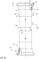
- FIG. 2 B is a side view of an embodiment of a hose assembly 220 (e.g., hose) that may incorporate one or more features of FIGS. 1 and 2 A .
- the hose assembly 220 may form at least a portion of a flow line, such as a flow line between a source and a pump, a pump and a manifold, or the like.
- This example illustrates fittings 200 from FIG. 2 A and further includes a body 222 (e.g., hose, hose portion), which is noted in FIG.
- first fitting 200 A is coupled at and/or at least partially forms a first end 224 and the second fitting 200 B is coupled at and/or at least partially forms a second end 226 .
- diameters associated with portions of the fittings 200 A, 200 B may be different from diameters associated with portions of the body 222 .
- the first fitting 200 A at the first end 224 includes a first diameter 228 and the second fitting 200 B at the second end 226 includes a second diameter 230 .
- the first diameter 228 and the second diameter 230 may be equal in various embodiments. As noted herein, the first diameter 228 and/or the second diameter 230 may be approximately 6′′. In at least one embodiment, the first diameter 228 is greater than the second diameter 230 . In at least one embodiment, the first diameter 228 is less than the second diameter 230 .
- a third diameter 232 is associated with the body 222 . In this embodiment, the third diameter 232 is smaller than the first diameter 228 and the second diameter 230 .
- the third diameter 232 may be approximately 5′′ while the first diameter 228 and/or the second diameter 230 is approximately 6′′. In at least one embodiment, the third diameter 232 may be equal to and/or greater than the first diameter 228 . In at least one embodiment, the third diameter 232 may be equal to and/or greater than the second diameter 230 .
- FIG. 3 is a schematic perspective view of an embodiment of a portion of a flow line 300 including the fitting 200 .
- the flow line 300 includes connections 302 for coupling to mating 6′′ connections.
- a 5′′ flow line may be incorporated into the design.
- the fitting 200 as noted above includes a transition from the 5′′ line to a 6′′ connection, thereby enabling use with the illustrated flow line 300 .
- the flow line 300 may continue to be used in wellbore operations without modifications, which may reduce costs to operators with respect to obtaining new equipment for jobs.
- embodiments of the present disclosure provide advantages over existing systems that either utilize flow lines having diameters that are too small to provide sufficient capacity or are too large to maintain fluid velocities above threshold levels.
- Embodiments of the present disclosure overcome these problems by providing more volume, reducing drop in pressure, and reducing a likelihood of cavitation and other unhealthy pump conditions, such as starving.
- frac slurry often consists of sand media also known as proppant, at low fluid velocities this proppant can begin to fall out of suspension.
- proppant Some industry data notes that sand fall out begins at 2.21 ft/sec, which equates to 3.2 BPM in a 5′′ hose.
- Sand fall out is substantial at 1.72 ft/sec, which equates to 2.2 BPM in a 5′′ hoses.
- systems may be deployed to ensure that flow rates are maintained above these levels (which may be set as the thresholds) during operation.
- embodiments of the present disclosure improve existing systems by reducing damage accumulation rates due to the improved flow characteristics associated with the 5′′ hose when compared to the 4′′ hose of existing systems.
- a damage accumulate rate associated with the 5′′ hose may be less than the 4′′ hose and may increase at a lower rate as flow rate increases. Damage accumulation may be a factor, at least in part, on flow velocities, where a small diameter pipe will have greater velocities than a larger diameter pipe.
- FIG. 4 is a graphical representation 400 illustrating pump flow rates and respective suction piping sizes.
- the x-axis 402 corresponds to suction pipe diameter (in inches) and the y-axis 404 corresponds to flow rate (in BPM).
- An operational window 406 is provided indicative of typical ranges where fracturing operations may occur. In this embodiment, the operational widow 406 extends from approximately 1 BPM to approximately 7 BPM.
- Each respective suction pipe diameter includes a threshold flow rate, which may be obtained through experimental procedures and/or reference materials.
- a 4′′ suction pipe illustrated at 408 has a threshold 410 of approximately 4.3 BPM
- a 5′′ suction pipe illustrated at 412 has a threshold 414 of approximately 5.5 BPM
- a 6′′ suction pipe illustrated at 416 has a threshold 418 of approximately 6.5 BPM.
- the operational window 406 includes a portion that exceeds each of the illustrated thresholds 410 , 414 , 418 .
- Operations using the 4′′ suction pipe 408 include an operating range that is approximately 40% larger than the threshold 410 . As a result, there is a high likelihood that operations will exceed the threshold due to demands to supply additional fluid for fracturing operations. Similarly, operations using the 5′′ suction pipe 412 and the 6′′ suction pipe 416 also exceed threshold 414 , 418 by approximately 22% and 7%, respectively.
- the instant application has identified that while the 6′′ suction pipe 416 enables the largest flow rate, that problems associated with fluid velocities and drop out make the 6′′ suction pipe 416 undesirable. Accordingly, embodiments may incorporate the 5′′ suction pipe 412 , which provides significant improvements over the 4′′ suction pipe 408 while also reducing the likelihood of drop out.
- the 5′′ suction pipe 412 also has less pressure drop, when compared to the 4′′ suction pipe 408 , providing an additional improvement over existing configurations.
Abstract
Description
Claims (20)
Priority Applications (2)
| Application Number | Priority Date | Filing Date | Title |
|---|---|---|---|
| US17/321,936 US11668420B2 (en) | 2019-12-27 | 2021-05-17 | System and method for integrated flow supply line |
| US18/206,313 US20240019057A1 (en) | 2019-12-27 | 2023-06-06 | System and method for integrated flow supply line |
Applications Claiming Priority (2)
| Application Number | Priority Date | Filing Date | Title |
|---|---|---|---|
| US16/728,359 US11009162B1 (en) | 2019-12-27 | 2019-12-27 | System and method for integrated flow supply line |
| US17/321,936 US11668420B2 (en) | 2019-12-27 | 2021-05-17 | System and method for integrated flow supply line |
Related Parent Applications (1)
| Application Number | Title | Priority Date | Filing Date |
|---|---|---|---|
| US16/728,359 Continuation US11009162B1 (en) | 2019-12-27 | 2019-12-27 | System and method for integrated flow supply line |
Related Child Applications (1)
| Application Number | Title | Priority Date | Filing Date |
|---|---|---|---|
| US18/206,313 Continuation US20240019057A1 (en) | 2019-12-27 | 2023-06-06 | System and method for integrated flow supply line |
Publications (2)
| Publication Number | Publication Date |
|---|---|
| US20220107039A1 US20220107039A1 (en) | 2022-04-07 |
| US11668420B2 true US11668420B2 (en) | 2023-06-06 |
Family
ID=75910393
Family Applications (3)
| Application Number | Title | Priority Date | Filing Date |
|---|---|---|---|
| US16/728,359 Active US11009162B1 (en) | 2019-12-27 | 2019-12-27 | System and method for integrated flow supply line |
| US17/321,936 Active US11668420B2 (en) | 2019-12-27 | 2021-05-17 | System and method for integrated flow supply line |
| US18/206,313 Pending US20240019057A1 (en) | 2019-12-27 | 2023-06-06 | System and method for integrated flow supply line |
Family Applications Before (1)
| Application Number | Title | Priority Date | Filing Date |
|---|---|---|---|
| US16/728,359 Active US11009162B1 (en) | 2019-12-27 | 2019-12-27 | System and method for integrated flow supply line |
Family Applications After (1)
| Application Number | Title | Priority Date | Filing Date |
|---|---|---|---|
| US18/206,313 Pending US20240019057A1 (en) | 2019-12-27 | 2023-06-06 | System and method for integrated flow supply line |
Country Status (2)
| Country | Link |
|---|---|
| US (3) | US11009162B1 (en) |
| AR (1) | AR120897A1 (en) |
Families Citing this family (1)
| Publication number | Priority date | Publication date | Assignee | Title |
|---|---|---|---|---|
| US11955782B1 (en) | 2022-11-01 | 2024-04-09 | Typhon Technology Solutions (U.S.), Llc | System and method for fracturing of underground formations using electric grid power |
Citations (71)
| Publication number | Priority date | Publication date | Assignee | Title |
|---|---|---|---|---|
| US2976025A (en) | 1958-10-16 | 1961-03-21 | Air Placement Equipment Compan | Combined mixer and conveyor |
| US4411313A (en) | 1981-10-19 | 1983-10-25 | Liquid Level Lectronics, Inc. | Pump |
| US4538916A (en) | 1984-06-20 | 1985-09-03 | Zimmerman Harold M | Motor mounting arrangement on a mixing auger |
| US4601629A (en) | 1984-06-20 | 1986-07-22 | Zimmerman Harold M | Fine and coarse aggregates conveying apparatus |
| US4603887A (en) * | 1984-10-01 | 1986-08-05 | Halliburton Company | Rigid adjustable length assembly |
| US4768884A (en) | 1987-03-03 | 1988-09-06 | Elkin Luther V | Cement mixer for fast setting materials |
| US5114239A (en) | 1989-09-21 | 1992-05-19 | Halliburton Company | Mixing apparatus and method |
| US5334899A (en) | 1991-09-30 | 1994-08-02 | Dymytro Skybyk | Polyphase brushless DC and AC synchronous machines |
| US5486047A (en) | 1995-06-05 | 1996-01-23 | Zimmerman; Harold M. | Mixing auger for concrete trucks |
| US5798596A (en) | 1996-07-03 | 1998-08-25 | Pacific Scientific Company | Permanent magnet motor with enhanced inductance |
| US5813455A (en) | 1997-03-11 | 1998-09-29 | Amoco Coporation | Chemical dispensing system |
| US5950726A (en) | 1996-08-06 | 1999-09-14 | Atlas Tool Company | Increased oil and gas production using elastic-wave stimulation |
| US6035265A (en) | 1997-10-08 | 2000-03-07 | Reliance Electric Industrial Company | System to provide low cost excitation to stator winding to generate impedance spectrum for use in stator diagnostics |
| US6097310A (en) | 1998-02-03 | 2000-08-01 | Baker Hughes Incorporated | Method and apparatus for mud pulse telemetry in underbalanced drilling systems |
| US6121705A (en) | 1996-12-31 | 2000-09-19 | Hoong; Fong Chean | Alternating pole AC motor/generator with two inner rotating rotors and an external static stator |
| US20010000996A1 (en) | 1998-03-06 | 2001-05-10 | Grimland Kristian E. | Multiple tub mobile blender |
| US6273193B1 (en) | 1997-12-16 | 2001-08-14 | Transocean Sedco Forex, Inc. | Dynamically positioned, concentric riser, drilling method and apparatus |
| US6442942B1 (en) | 1999-06-10 | 2002-09-03 | Enhanced Turbine Output Holding, Llc | Supercharging system for gas turbines |
| US6585455B1 (en) | 1992-08-18 | 2003-07-01 | Shell Oil Company | Rocker arm marine tensioning system |
| US20040045703A1 (en) | 2002-09-05 | 2004-03-11 | Hooper Robert C. | Apparatus for positioning and stabbing pipe in a drilling rig derrick |
| US6788022B2 (en) | 2002-10-21 | 2004-09-07 | A. O. Smith Corporation | Electric motor |
| US20050201197A1 (en) | 2004-03-10 | 2005-09-15 | Duell Alan B. | System and method for mixing water and non-aqueous materials using measured water concentration to control addition of ingredients |
| US20060109141A1 (en) | 2002-09-06 | 2006-05-25 | Songming Huang | Noise attenuation apparatus for borehole telemetry |
| US20080164023A1 (en) | 2005-04-14 | 2008-07-10 | Halliburton Energy Services, Inc. | Method for Servicing a Well Bore Using a Mixing Control System |
| US20080257449A1 (en) | 2007-04-17 | 2008-10-23 | Halliburton Energy Services, Inc. | Dry additive metering into portable blender tub |
| US20090072645A1 (en) | 2007-09-13 | 2009-03-19 | Eric Stephane Quere | Composite electromechanical machines with gear mechanism |
| WO2009046280A1 (en) | 2007-10-05 | 2009-04-09 | Weatherford/Lanb, Inc. | Quintuplex mud pump |
| US7795830B2 (en) | 2005-07-06 | 2010-09-14 | Elckon Limited | Electric motor |
| US20110081268A1 (en) | 2009-08-13 | 2011-04-07 | Brian Ochoa | Pump body |
| US20110110793A1 (en) | 2009-11-06 | 2011-05-12 | Edward Leugemors | Suction stabilizer for pump assembly |
| US20120063936A1 (en) | 2010-09-10 | 2012-03-15 | Phoinix Global LLC | Modular fluid end for a multiplex plunger pump |
| US20120112757A1 (en) | 2010-11-10 | 2012-05-10 | Vrankovic Zoran V | Ground Fault Detection and Location System and Method for Motor Drives |
| US20120150455A1 (en) | 2009-08-18 | 2012-06-14 | Franklin Charles M | System and Method for Determining Leaks in a Complex System |
| US20130051971A1 (en) | 2011-08-29 | 2013-02-28 | Gene Wyse | Expandable Stowable Platform for Unloading Trucks |
| US20140174717A1 (en) | 2012-11-16 | 2014-06-26 | Us Well Services Llc | System for pumping hydraulic fracturing fluid using electric pumps |
| CN104117308A (en) | 2014-07-28 | 2014-10-29 | 丹阳市海信涂料化工厂 | Device for mixing and preparing coating |
| WO2014177346A1 (en) | 2013-05-03 | 2014-11-06 | Siemens Aktiengesellschaft | Power system for a floating vessel |
| US20150147194A1 (en) | 2012-10-17 | 2015-05-28 | Global Energy Services, Inc. | Segmented fluid end |
| US20150233530A1 (en) | 2014-02-20 | 2015-08-20 | Pcs Ferguson, Inc. | Method and system to volumetrically control additive pump |
| US9140105B2 (en) | 2011-10-11 | 2015-09-22 | Lance N. Pattillo | Temporary support device for oil well tubes and method of use |
| US20160006311A1 (en) | 2014-06-19 | 2016-01-07 | Turboroto Inc. | Electric motor, generator and commutator system, device and method |
| US9353593B1 (en) | 2015-03-13 | 2016-05-31 | National Oilwell Varco, Lp | Handler for blowout preventer assembly |
| US20160230660A1 (en) | 2015-02-10 | 2016-08-11 | Univ King Saud | Gas turbine power generator with two-stage inlet air cooling |
| US20170096889A1 (en) | 2014-03-28 | 2017-04-06 | Schlumberger Technology Corporation | System and method for automation of detection of stress patterns and equipment failures in hydrocarbon extraction and production |
| US20170204852A1 (en) | 2016-01-15 | 2017-07-20 | W.H. Barnett, JR. | Segmented fluid end |
| US20170218727A1 (en) * | 2012-11-16 | 2017-08-03 | Us Well Services Llc | System for fueling electric powered hydraulic fracturing equipment with multiple fuel sources |
| US9790858B2 (en) | 2013-03-26 | 2017-10-17 | Mitsubishi Hitachi Power Systems, Ltd. | Intake-air cooling device |
| US9945365B2 (en) | 2014-04-16 | 2018-04-17 | Bj Services, Llc | Fixed frequency high-pressure high reliability pump drive |
| US20180181830A1 (en) | 2015-06-05 | 2018-06-28 | Schlumberger Technology Corporation | Wellsite equipment health monitoring |
| US20180313677A1 (en) | 2015-12-22 | 2018-11-01 | Halliburton Energy Services ,Inc. | System and method for determining slurry sand concentration and continuous calibration of metering mechanisms for transferring same |
| US20180366950A1 (en) | 2015-12-07 | 2018-12-20 | Maersk Drilling A/S | Microgrid electric power generation systems and associated methods |
| US20180363640A1 (en) | 2015-12-19 | 2018-12-20 | Schlumberger Technology Corporation | Automated operation of wellsite pumping equipment |
| US20190040727A1 (en) | 2012-11-16 | 2019-02-07 | U.S. Well Services, LLC | System for reducing vibrations in a pressure pumping fleet |
| US20190128104A1 (en) | 2017-11-02 | 2019-05-02 | Caterpillar Inc. | Method of remanufacturing fluid end block |
| US20190145251A1 (en) | 2017-11-13 | 2019-05-16 | Shear Frac Inc | Hydraulic Fracturing |
| US20190257462A1 (en) | 2017-10-26 | 2019-08-22 | Performance Pulsation Control, Inc. | System pulsation dampener device(s) substituting for pulsation dampeners utilizing compression material therein |
| US10415332B2 (en) | 2017-06-29 | 2019-09-17 | Typhon Technology Solutions, Llc | Hydration-blender transport for fracturing operation |
| WO2019210417A1 (en) | 2018-05-01 | 2019-11-07 | David Sherman | Powertrain for wellsite operations and method |
| US10480300B2 (en) * | 2016-05-01 | 2019-11-19 | Cameron International Corporation | Fracturing system with flexible conduit |
| US20200040878A1 (en) | 2018-08-06 | 2020-02-06 | Typhon Technology Solutions, Llc | Engagement and disengagement with external gear box style pumps |
| US10648270B2 (en) | 2018-09-14 | 2020-05-12 | U.S. Well Services, LLC | Riser assist for wellsites |
| US10648311B2 (en) | 2017-12-05 | 2020-05-12 | U.S. Well Services, LLC | High horsepower pumping configuration for an electric hydraulic fracturing system |
| US10686301B2 (en) | 2012-11-16 | 2020-06-16 | U.S. Well Services, LLC | Switchgear load sharing for oil field equipment |
| US10731561B2 (en) | 2012-11-16 | 2020-08-04 | U.S. Well Services, LLC | Turbine chilling for oil field power generation |
| US10767561B2 (en) | 2014-10-10 | 2020-09-08 | Stellar Energy Americas, Inc. | Method and apparatus for cooling the ambient air at the inlet of gas combustion turbine generators |
| US10781752B2 (en) | 2016-03-23 | 2020-09-22 | Chiyoda Corporation | Inlet air cooling system and inlet air cooling method for gas turbine |
| US10794165B2 (en) | 2019-02-14 | 2020-10-06 | National Service Alliance—Houston LLC | Power distribution trailer for an electric driven hydraulic fracking system |
| US20200325760A1 (en) | 2019-04-12 | 2020-10-15 | The Modern Group, Ltd. | Hydraulic fracturing pump system |
| US20200350790A1 (en) | 2019-04-30 | 2020-11-05 | Alloy Energy Solutions Inc. | Modular, mobile power system for equipment operations, and methods for operating same |
| CN112196508A (en) | 2020-09-30 | 2021-01-08 | 中国石油天然气集团有限公司 | Full-automatic liquid adding device for fracturing construction and adding calibration method |
| US10988998B2 (en) | 2019-02-14 | 2021-04-27 | National Service Alliance—Houston LLC | Electric driven hydraulic fracking operation |
Family Cites Families (403)
| Publication number | Priority date | Publication date | Assignee | Title |
|---|---|---|---|---|
| US1656861A (en) | 1923-09-15 | 1928-01-17 | Doherty Res Co | Derrick |
| US1671436A (en) | 1926-11-10 | 1928-05-29 | John M Melott | Flexible coupling |
| US2004077A (en) | 1934-07-16 | 1935-06-04 | William J Mccartney | Coupling |
| US2183364A (en) | 1936-04-13 | 1939-12-12 | Thermal Engineering Company | Control means for a plurality of power units |
| US2220622A (en) | 1937-06-10 | 1940-11-05 | Homer Paul Aitken | Flexible insulated coupling |
| US2248051A (en) | 1938-12-28 | 1941-07-08 | Sun Oil Co | Offshore drilling rig |
| US2416848A (en) | 1943-02-23 | 1947-03-04 | Rothery James Stewart | Lifting jack |
| US2407796A (en) | 1943-08-17 | 1946-09-17 | Herbert E Page | Tripod jack |
| US2610741A (en) * | 1950-06-17 | 1952-09-16 | J A Zurn Mfg Company | Strainer |
| US2753940A (en) | 1953-05-11 | 1956-07-10 | Exxon Research Engineering Co | Method and apparatus for fracturing a subsurface formation |
| US3055682A (en) * | 1955-10-11 | 1962-09-25 | Aeroquip Corp | Adjustment fitting for reinforced hose in which a seal is maintained during adjustment |
| US3061039A (en) | 1957-11-14 | 1962-10-30 | Joseph J Mascuch | Fluid line sound-absorbing structures |
| US3066503A (en) | 1961-05-23 | 1962-12-04 | Gen Tire & Rubber Co | Formed tube coupling |
| GB1102759A (en) | 1964-06-25 | 1968-02-07 | Merz And Mclellan Services Ltd | Improvements relating to electric switchgear |
| US3334495A (en) | 1965-12-03 | 1967-08-08 | Carrier Corp | Breach-lock coupling |
| US3722595A (en) | 1971-01-25 | 1973-03-27 | Exxon Production Research Co | Hydraulic fracturing method |
| US3764233A (en) | 1971-11-15 | 1973-10-09 | Us Navy | Submersible motor-pump assembly |
| DE2211512A1 (en) | 1972-03-10 | 1973-10-18 | Barth Harald | ELASTIC CLAW COUPLING WITH TWO COUPLING DISCS IN ESSENTIAL DESIGN |
| US3773140A (en) | 1972-05-30 | 1973-11-20 | Continental Can Co | Noise attenuating kit |
| US3849662A (en) | 1973-01-02 | 1974-11-19 | Combustion Eng | Combined steam and gas turbine power plant having gasified coal fuel supply |
| US3878884A (en) | 1973-04-02 | 1975-04-22 | Cecil B Raleigh | Formation fracturing method |
| US3881551A (en) | 1973-10-12 | 1975-05-06 | Ruel C Terry | Method of extracting immobile hydrocarbons |
| JPS5325062Y2 (en) | 1975-05-20 | 1978-06-27 | ||
| US4100822A (en) | 1976-04-19 | 1978-07-18 | Allan Rosman | Drive system for a moving mechanism |
| US4151575A (en) | 1977-03-07 | 1979-04-24 | Hogue Maurice A | Motor protective device |
| US4226299A (en) | 1978-05-22 | 1980-10-07 | Alphadyne, Inc. | Acoustical panel |
| US4265266A (en) | 1980-01-23 | 1981-05-05 | Halliburton Company | Controlled additive metering system |
| JPS601236Y2 (en) | 1980-09-22 | 1985-01-14 | 日産自動車株式会社 | engine surface shielding plate |
| US4442665A (en) | 1980-10-17 | 1984-04-17 | General Electric Company | Coal gasification power generation plant |
| US4432064A (en) | 1980-10-27 | 1984-02-14 | Halliburton Company | Apparatus for monitoring a plurality of operations |
| US4506982A (en) | 1981-08-03 | 1985-03-26 | Union Oil Company Of California | Apparatus for continuously blending viscous liquids with particulate solids |
| US4512387A (en) | 1982-05-28 | 1985-04-23 | Rodriguez Larry A | Power transformer waste heat recovery system |
| FI86435C (en) | 1983-05-31 | 1992-08-25 | Siemens Ag | Medium load power plant with an integrated carbon gasification plant |
| US4529887A (en) | 1983-06-20 | 1985-07-16 | General Electric Company | Rapid power response turbine |
| DE3513999C1 (en) | 1985-04-18 | 1986-10-09 | Deutsche Gesellschaft für Wiederaufarbeitung von Kernbrennstoffen mbH, 3000 Hannover | Remote-controlled positioning and carrying device for remote handling devices |
| US5006044A (en) | 1987-08-19 | 1991-04-09 | Walker Sr Frank J | Method and system for controlling a mechanical pump to monitor and optimize both reservoir and equipment performance |
| US4793386A (en) | 1987-09-03 | 1988-12-27 | Sloan Pump Company, Inc. | Apparatus and method using portable pump |
| US4922463A (en) | 1988-08-22 | 1990-05-01 | Del Zotto Manufacturing Co. | Portable volumetric concrete mixer/silo |
| US4845981A (en) | 1988-09-13 | 1989-07-11 | Atlantic Richfield Company | System for monitoring fluids during well stimulation processes |
| US5004400A (en) | 1989-04-13 | 1991-04-02 | Halliburton Company | Automatic rate matching system |
| US5025861A (en) | 1989-12-15 | 1991-06-25 | Schlumberger Technology Corporation | Tubing and wireline conveyed perforating method and apparatus |
| US5050673A (en) | 1990-05-15 | 1991-09-24 | Halliburton Company | Lift through plug container for slant rig |
| US5130628A (en) | 1990-06-28 | 1992-07-14 | Southwest Electric Company | Transformer providing two multiple phase outputs out of phase with each other, and pumping system using the same |
| GB2250763B (en) | 1990-12-13 | 1995-08-02 | Ltv Energy Prod Co | Riser tensioner system for use on offshore platforms using elastomeric pads or helical metal compression springs |
| US5786642A (en) | 1991-01-08 | 1998-07-28 | Nextek Power Systems Inc. | Modular power management system and method |
| US5172009A (en) | 1991-02-25 | 1992-12-15 | Regents Of The University Of Minnesota | Standby power supply with load-current harmonics neutralizer |
| US5189388A (en) | 1991-03-04 | 1993-02-23 | Mosley Judy A | Oil well pump start-up alarm |
| US5131472A (en) | 1991-05-13 | 1992-07-21 | Oryx Energy Company | Overbalance perforating and stimulation method for wells |
| US5230366A (en) * | 1992-07-09 | 1993-07-27 | Griswold Controls | Automatic fluid flow control device |
| US5433243A (en) * | 1992-07-09 | 1995-07-18 | Griswold Controls | Fluid flow control device and method |
| US5422550A (en) | 1993-05-27 | 1995-06-06 | Southwest Electric Company | Control of multiple motors, including motorized pumping system and method |
| US5517822A (en) | 1993-06-15 | 1996-05-21 | Applied Energy Systems Of Oklahoma, Inc. | Mobile congeneration apparatus including inventive valve and boiler |
| JPH0763132A (en) | 1993-08-20 | 1995-03-07 | Toyoda Gosei Co Ltd | Muffling hose for air intake system of internal combustion engine |
| DE69318734D1 (en) | 1993-12-06 | 1998-06-25 | Thermo Instr Controls Ltd | SYSTEM AND METHOD FOR INJECTING CELLULOSE |
| US5469045A (en) | 1993-12-07 | 1995-11-21 | Dove; Donald C. | High speed power factor controller |
| US5439066A (en) | 1994-06-27 | 1995-08-08 | Fleet Cementers, Inc. | Method and system for downhole redirection of a borehole |
| EP0702141B1 (en) | 1994-09-14 | 2002-05-08 | Mitsubishi Jukogyo Kabushiki Kaisha | Wall assembly for an exhaust gas nozzle of a supersonic jet engine |
| US5716260A (en) | 1995-02-03 | 1998-02-10 | Ecolab Inc. | Apparatus and method for cleaning and restoring floor surfaces |
| US5590976A (en) | 1995-05-30 | 1997-01-07 | Akzo Nobel Ashpalt Applications, Inc. | Mobile paving system using an aggregate moisture sensor and method of operation |
| US5790972A (en) | 1995-08-24 | 1998-08-04 | Kohlenberger; Charles R. | Method and apparatus for cooling the inlet air of gas turbine and internal combustion engine prime movers |
| SE9602079D0 (en) | 1996-05-29 | 1996-05-29 | Asea Brown Boveri | Rotating electric machines with magnetic circuit for high voltage and a method for manufacturing the same |
| US5755096A (en) | 1996-07-15 | 1998-05-26 | Holleyman; John E. | Filtered fuel gas for pressurized fluid engine systems |
| US5879137A (en) | 1997-01-22 | 1999-03-09 | Jetec Corporation | Method and apparatus for pressurizing fluids |
| JP3202657B2 (en) | 1997-05-23 | 2001-08-27 | 日本電気株式会社 | Method for manufacturing semiconductor device |
| US5894888A (en) | 1997-08-21 | 1999-04-20 | Chesapeake Operating, Inc | Horizontal well fracture stimulation methods |
| US5907970A (en) | 1997-10-15 | 1999-06-01 | Havlovick; Bradley J. | Take-off power package system |
| US6208098B1 (en) | 1998-03-02 | 2001-03-27 | Yaskawa Electric America, Inc. | Variable frequency drive noise attenuation circuit |
| US6758231B1 (en) | 1998-06-17 | 2004-07-06 | Light Wave Ltd. | Redundant array control system for water rides |
| US6164910A (en) | 1998-09-22 | 2000-12-26 | Itt Manufacturing Enterprises, Inc. | Housing assembly for a fluid-working device such as a rotary pump |
| US6142878A (en) | 1998-11-23 | 2000-11-07 | Barin; Jose Florian B. | Flexible coupling with elastomeric belt |
| US6138764A (en) | 1999-04-26 | 2000-10-31 | Camco International, Inc. | System and method for deploying a wireline retrievable tool in a deviated well |
| US6271637B1 (en) | 1999-09-17 | 2001-08-07 | Delphi Technologies, Inc. | Diagnostic system for electric motor |
| US6529135B1 (en) | 1999-10-12 | 2003-03-04 | Csi Technology, Inc. | Integrated electric motor monitor |
| CA2294679C (en) | 2000-01-06 | 2007-10-09 | Shishiai-Kabushikigaisha | Acoustic damping pipe cover |
| US6315523B1 (en) | 2000-02-18 | 2001-11-13 | Djax Corporation | Electrically isolated pump-off controller |
| JP3750474B2 (en) | 2000-03-08 | 2006-03-01 | 株式会社日立製作所 | Cogeneration facility and operation method thereof |
| US8760657B2 (en) | 2001-04-11 | 2014-06-24 | Gas Sensing Technology Corp | In-situ detection and analysis of methane in coal bed methane formations with spectrometers |
| CA2406801C (en) | 2000-04-26 | 2007-01-02 | Pinnacle Technologies, Inc. | Treatment well tiltmeter system |
| US6484490B1 (en) | 2000-05-09 | 2002-11-26 | Ingersoll-Rand Energy Systems Corp. | Gas turbine system and method |
| MXPA02001430A (en) * | 2000-06-09 | 2004-07-16 | Agricultural Products Inc | An agricultural or industrial spin filter and a method of operation for same. |
| US6937923B1 (en) | 2000-11-01 | 2005-08-30 | Weatherford/Lamb, Inc. | Controller system for downhole applications |
| US6491098B1 (en) | 2000-11-07 | 2002-12-10 | L. Murray Dallas | Method and apparatus for perforating and stimulating oil wells |
| JP3746483B2 (en) | 2000-11-10 | 2006-02-15 | ジョン・カニンガム | Swivel support structure and vibration isolation structure |
| US6560131B1 (en) | 2001-02-13 | 2003-05-06 | Vonbrethorst William F. | Stored energy power system |
| US6757590B2 (en) | 2001-03-15 | 2004-06-29 | Utc Fuel Cells, Llc | Control of multiple fuel cell power plants at a site to provide a distributed resource in a utility grid |
| US6802690B2 (en) | 2001-05-30 | 2004-10-12 | M & I Heat Transfer Products, Ltd. | Outlet silencer structures for turbine |
| EP1270309B1 (en) | 2001-06-29 | 2012-09-12 | Ford Global Technologies, LLC | Device and method for supplying an electrical vehicle with electrical energy |
| WO2003012271A1 (en) | 2001-08-01 | 2003-02-13 | Pipeline Controls, Inc. | Modular fuel conditioning system |
| US6705398B2 (en) | 2001-08-03 | 2004-03-16 | Schlumberger Technology Corporation | Fracture closure pressure determination |
| US7336514B2 (en) | 2001-08-10 | 2008-02-26 | Micropulse Technologies | Electrical power conservation apparatus and method |
| US8413262B2 (en) | 2004-05-28 | 2013-04-09 | Matscitechno Licensing Company | Sound dissipating material |
| US6765304B2 (en) | 2001-09-26 | 2004-07-20 | General Electric Co. | Mobile power generation unit |
| CA2359441C (en) | 2001-10-19 | 2005-10-18 | Robert C. Rajewski | In-line gas compression system |
| US20030138327A1 (en) | 2002-01-18 | 2003-07-24 | Robert Jones | Speed control for a pumping system |
| CA2375565C (en) | 2002-03-08 | 2004-06-22 | Rodney T. Beida | Wellhead heating apparatus and method |
| US20030205376A1 (en) | 2002-04-19 | 2003-11-06 | Schlumberger Technology Corporation | Means and Method for Assessing the Geometry of a Subterranean Fracture During or After a Hydraulic Fracturing Treatment |
| US20080017369A1 (en) | 2002-07-18 | 2008-01-24 | Sarada Steven A | Method and apparatus for generating pollution free electrical energy from hydrocarbons |
| US6820702B2 (en) | 2002-08-27 | 2004-11-23 | Noble Drilling Services Inc. | Automated method and system for recognizing well control events |
| JP3661671B2 (en) | 2002-09-03 | 2005-06-15 | 日産自動車株式会社 | Vehicle drive control device |
| US20050061548A1 (en) | 2002-09-05 | 2005-03-24 | Hooper Robert C. | Apparatus for positioning and stabbing pipe in a drilling rig derrick |
| WO2004042887A2 (en) | 2002-09-18 | 2004-05-21 | Sure Power Corporation | Dc power system for marine vessels |
| US6882960B2 (en) | 2003-02-21 | 2005-04-19 | J. Davis Miller | System and method for power pump performance monitoring and analysis |
| JP3680061B2 (en) | 2003-02-28 | 2005-08-10 | 株式会社東芝 | Wall member |
| US6808303B2 (en) | 2003-03-18 | 2004-10-26 | Suzanne Medley | Ready mix batch hauler system |
| US7562025B2 (en) | 2003-09-19 | 2009-07-14 | Vesta Medical, Llc | Waste sorting system with query function, and method thereof |
| US7388303B2 (en) | 2003-12-01 | 2008-06-17 | Conocophillips Company | Stand-alone electrical system for large motor loads |
| US7170262B2 (en) | 2003-12-24 | 2007-01-30 | Foundation Enterprises Ltd. | Variable frequency power system and method of use |
| CA2501664A1 (en) | 2004-04-22 | 2005-10-22 | Briggs And Stratton Corporation | Engine oil heater |
| US7320374B2 (en) | 2004-06-07 | 2008-01-22 | Varco I/P, Inc. | Wellbore top drive systems |
| US7633772B2 (en) | 2004-09-20 | 2009-12-15 | Ullrich Joseph Arnold | AC power distribution system with transient suppression and harmonic attenuation |
| US20060065319A1 (en) * | 2004-09-24 | 2006-03-30 | Mikulas Csitari | QuickFlush valve kit for flushing of inboard/outboard marine engine cooling system |
| US7563076B2 (en) | 2004-10-27 | 2009-07-21 | Halliburton Energy Services, Inc. | Variable rate pumping system |
| JP4509742B2 (en) | 2004-11-04 | 2010-07-21 | 株式会社日立製作所 | Gas turbine power generation equipment |
| US7308933B1 (en) | 2004-11-10 | 2007-12-18 | Paal, L.L.C. | Power assisted lift for lubricator assembly |
| US7494263B2 (en) | 2005-04-14 | 2009-02-24 | Halliburton Energy Services, Inc. | Control system design for a mixing system with multiple inputs |
| US7173399B2 (en) | 2005-04-19 | 2007-02-06 | General Electric Company | Integrated torsional mode damping system and method |
| US7525264B2 (en) | 2005-07-26 | 2009-04-28 | Halliburton Energy Services, Inc. | Shunt regulation apparatus, systems, and methods |
| NO20055727L (en) | 2005-12-05 | 2007-06-06 | Norsk Hydro Produksjon As | Electric underwater compression system |
| US7370703B2 (en) | 2005-12-09 | 2008-05-13 | Baker Hughes Incorporated | Downhole hydraulic pipe cutter |
| EP1999492A4 (en) | 2006-01-20 | 2011-05-18 | Landmark Graphics Corp | Dynamic production system management |
| US7445041B2 (en) | 2006-02-06 | 2008-11-04 | Shale And Sands Oil Recovery Llc | Method and system for extraction of hydrocarbons from oil shale |
| US7807048B2 (en) | 2006-02-09 | 2010-10-05 | Collette Jerry R | Thermal recovery of petroleum crude oil from tar sands and oil shale deposits |
| US20070187163A1 (en) | 2006-02-10 | 2007-08-16 | Deere And Company | Noise reducing side shields |
| US20070201305A1 (en) | 2006-02-27 | 2007-08-30 | Halliburton Energy Services, Inc. | Method and apparatus for centralized proppant storage and metering |
| WO2011008716A2 (en) | 2009-07-11 | 2011-01-20 | Stephen Degaray | System and process for delivering building materials |
| US9738461B2 (en) | 2007-03-20 | 2017-08-22 | Pump Truck Industrial LLC | System and process for delivering building materials |
| US20070226089A1 (en) | 2006-03-23 | 2007-09-27 | Degaray Stephen | System and method for distributing building materials in a controlled manner |
| RU2008145876A (en) | 2006-04-21 | 2010-05-27 | Шелл Интернэшнл Рисерч Маатсхаппий Б.В. (NL) | HEATERS WITH RESTRICTION OF TEMPERATURE WHICH USE PHASE TRANSFORMATION OF FERROMAGNETIC MATERIAL |
| US7683499B2 (en) | 2006-04-27 | 2010-03-23 | S & W Holding, Inc. | Natural gas turbine generator |
| US7845413B2 (en) | 2006-06-02 | 2010-12-07 | Schlumberger Technology Corporation | Method of pumping an oilfield fluid and split stream oilfield pumping systems |
| JP4790801B2 (en) | 2006-06-19 | 2011-10-12 | 三菱電機株式会社 | Gas insulated power equipment |
| US20080041596A1 (en) | 2006-08-18 | 2008-02-21 | Conocophillips Company | Coiled tubing well tool and method of assembly |
| US7312593B1 (en) | 2006-08-21 | 2007-12-25 | Rockwell Automation Technologies, Inc. | Thermal regulation of AC drive |
| US20080217024A1 (en) | 2006-08-24 | 2008-09-11 | Western Well Tool, Inc. | Downhole tool with closed loop power systems |
| US20080137266A1 (en) | 2006-09-29 | 2008-06-12 | Rockwell Automation Technologies, Inc. | Motor control center with power and data distribution bus |
| US7642663B2 (en) | 2006-10-19 | 2010-01-05 | Bidell Equipment Limited Partnership | Mobile wear and tear resistant gas compressor |
| US7681399B2 (en) | 2006-11-14 | 2010-03-23 | General Electric Company | Turbofan engine cowl assembly and method of operating the same |
| ATE497244T1 (en) | 2007-02-02 | 2011-02-15 | Abb Research Ltd | SWITCHING DEVICE, USE THEREOF AND METHOD FOR SWITCHING |
| NZ580322A (en) | 2007-03-14 | 2012-11-30 | Zonit Structured Solutions Llc | Controlling electrical appliances using TCP/IP controlled outlets with power interruption or reduction functions |
| US8016041B2 (en) | 2007-03-28 | 2011-09-13 | Kerfoot William B | Treatment for recycling fracture water gas and oil recovery in shale deposits |
| US20080264625A1 (en) | 2007-04-26 | 2008-10-30 | Brian Ochoa | Linear electric motor for an oilfield pump |
| US20080264649A1 (en) | 2007-04-29 | 2008-10-30 | Crawford James D | Modular well servicing combination unit |
| BRPI0721568A8 (en) | 2007-05-04 | 2019-01-15 | Ericsson Telefon Ab L M | power supply station, and remote power system to provide electric power |
| US7806175B2 (en) | 2007-05-11 | 2010-10-05 | Stinger Wellhead Protection, Inc. | Retrivevable frac mandrel and well control stack to facilitate well completion, re-completion or workover and method of use |
| US8774972B2 (en) | 2007-05-14 | 2014-07-08 | Flowserve Management Company | Intelligent pump system |
| NL1034120C2 (en) | 2007-07-12 | 2009-01-13 | B B A Participaties B V | Soundproof housing for a pump and a drive motor for that pump. |
| US7675189B2 (en) | 2007-07-17 | 2010-03-09 | Baseload Energy, Inc. | Power generation system including multiple motors/generators |
| US20120205301A1 (en) | 2007-08-02 | 2012-08-16 | Mcguire Dennis | Apparatus for treating fluids |
| US20090045782A1 (en) | 2007-08-16 | 2009-02-19 | General Electric Company | Power conversion system |
| US8506267B2 (en) | 2007-09-10 | 2013-08-13 | Schlumberger Technology Corporation | Pump assembly |
| US7755310B2 (en) | 2007-09-11 | 2010-07-13 | Gm Global Technology Operations, Inc. | Method and apparatus for electric motor torque monitoring |
| AU2008299076B2 (en) | 2007-09-13 | 2012-05-17 | M-I Llc | Method and system for injecting a slurry downhole |
| US20090078410A1 (en) | 2007-09-21 | 2009-03-26 | David Krenek | Aggregate Delivery Unit |
| JP2009092121A (en) | 2007-10-05 | 2009-04-30 | Enplas Corp | Rotary shaft coupling |
| US7931082B2 (en) | 2007-10-16 | 2011-04-26 | Halliburton Energy Services Inc., | Method and system for centralized well treatment |
| US7717193B2 (en) | 2007-10-23 | 2010-05-18 | Nabors Canada | AC powered service rig |
| US8146665B2 (en) | 2007-11-13 | 2012-04-03 | Halliburton Energy Services Inc. | Apparatus and method for maintaining boost pressure to high-pressure pumps during wellbore servicing operations |
| US8333243B2 (en) | 2007-11-15 | 2012-12-18 | Vetco Gray Inc. | Tensioner anti-rotation device |
| US8154419B2 (en) | 2007-12-14 | 2012-04-10 | Halliburton Energy Services Inc. | Oilfield area network communication system and method |
| US8162051B2 (en) | 2008-01-04 | 2012-04-24 | Intelligent Tools Ip, Llc | Downhole tool delivery system with self activating perforation gun |
| US8037936B2 (en) | 2008-01-16 | 2011-10-18 | Baker Hughes Incorporated | Method of heating sub sea ESP pumping system |
| US20090188181A1 (en) | 2008-01-28 | 2009-07-30 | Forbis Jack R | Innovative, modular, highly-insulating panel and method of use thereof |
| WO2009101125A1 (en) | 2008-02-15 | 2009-08-20 | Shell Internationale Research Maatschappij B.V. | Method of producing hydrocarbons through a smart well |
| GB2458637A (en) | 2008-03-25 | 2009-09-30 | Adrian Bowen | Wiper ball launcher |
| WO2009129289A2 (en) | 2008-04-15 | 2009-10-22 | Schlumberger Canada Limited | Formation treatment evaluation |
| US8096354B2 (en) | 2008-05-15 | 2012-01-17 | Schlumberger Technology Corporation | Sensing and monitoring of elongated structures |
| CA2634861C (en) | 2008-06-11 | 2011-01-04 | Hitman Holdings Ltd. | Combined three-in-one fracturing system |
| GB2465505C (en) | 2008-06-27 | 2020-10-14 | Rasheed Wajid | Electronically activated underreamer and calliper tool |
| US20130189629A1 (en) | 2008-07-07 | 2013-07-25 | Ronald L. Chandler | Frac water heater and fuel oil heating system |
| US8534235B2 (en) | 2008-07-07 | 2013-09-17 | Ronald L. Chandler | Oil-fired frac water heater |
| US20100019574A1 (en) | 2008-07-24 | 2010-01-28 | John Baldassarre | Energy management system for auxiliary power source |
| US20100038907A1 (en) | 2008-08-14 | 2010-02-18 | EncoGen LLC | Power Generation |
| US20100051272A1 (en) | 2008-09-02 | 2010-03-04 | Gas-Frac Energy Services Inc. | Liquified petroleum gas fracturing methods |
| MX2011003461A (en) | 2008-10-03 | 2011-05-19 | Schlumberger Technology Bv | Configurable hydraulic system. |
| US8360152B2 (en) | 2008-10-21 | 2013-01-29 | Encana Corporation | Process and process line for the preparation of hydraulic fracturing fluid |
| JP2010107636A (en) | 2008-10-29 | 2010-05-13 | Kyocera Mita Corp | Image forming apparatus |
| EP2366066A2 (en) | 2008-12-03 | 2011-09-21 | Oasys Water, Inc. | Utility scale osmotic grid storage |
| US8692408B2 (en) | 2008-12-03 | 2014-04-08 | General Electric Company | Modular stacked subsea power system architectures |
| US9470149B2 (en) | 2008-12-11 | 2016-10-18 | General Electric Company | Turbine inlet air heat pump-type system |
| WO2010078350A1 (en) | 2008-12-30 | 2010-07-08 | Kirk Hobbs | Mobile platform for monitoring a wellsite |
| US8177411B2 (en) | 2009-01-08 | 2012-05-15 | Halliburton Energy Services Inc. | Mixer system controlled based on density inferred from sensed mixing tub weight |
| CA2689820A1 (en) | 2009-01-13 | 2010-07-13 | Miva Engineering Ltd. | Reciprocating pump |
| US8091928B2 (en) * | 2009-02-26 | 2012-01-10 | Eaton Corporation | Coupling assembly for connection to a hose |
| US8851860B1 (en) | 2009-03-23 | 2014-10-07 | Tundra Process Solutions Ltd. | Adaptive control of an oil or gas well surface-mounted hydraulic pumping system and method |
| US20100293973A1 (en) | 2009-04-20 | 2010-11-25 | Donald Charles Erickson | Combined cycle exhaust powered turbine inlet air chilling |
| US8054084B2 (en) | 2009-05-19 | 2011-11-08 | GM Global Technology Operations LLC | Methods and systems for diagnosing stator windings in an electric motor |
| US8807960B2 (en) | 2009-06-09 | 2014-08-19 | Halliburton Energy Services, Inc. | System and method for servicing a wellbore |
| US9556874B2 (en) | 2009-06-09 | 2017-01-31 | Pentair Flow Technologies, Llc | Method of controlling a pump and motor |
| US8354817B2 (en) | 2009-06-18 | 2013-01-15 | GM Global Technology Operations LLC | Methods and systems for diagnosing stator windings in an electric motor |
| WO2011005571A2 (en) | 2009-06-23 | 2011-01-13 | Weir Spm, Inc. | Readily removable pump crosshead |
| US8310272B2 (en) | 2009-07-29 | 2012-11-13 | GM Global Technology Operations LLC | Method and system for testing electric automotive drive systems |
| US8763387B2 (en) | 2009-08-10 | 2014-07-01 | Howard K. Schmidt | Hydraulic geofracture energy storage system |
| US10669471B2 (en) | 2009-08-10 | 2020-06-02 | Quidnet Energy Inc. | Hydraulic geofracture energy storage system with desalination |
| US8874383B2 (en) | 2009-09-03 | 2014-10-28 | Schlumberger Technology Corporation | Pump assembly |
| US8616005B1 (en) | 2009-09-09 | 2013-12-31 | Dennis James Cousino, Sr. | Method and apparatus for boosting gas turbine engine performance |
| US8834012B2 (en) | 2009-09-11 | 2014-09-16 | Halliburton Energy Services, Inc. | Electric or natural gas fired small footprint fracturing fluid blending and pumping equipment |
| US20110085924A1 (en) | 2009-10-09 | 2011-04-14 | Rod Shampine | Pump assembly vibration absorber system |
| US8232892B2 (en) | 2009-11-30 | 2012-07-31 | Tiger General, Llc | Method and system for operating a well service rig |
| US20130180722A1 (en) | 2009-12-04 | 2013-07-18 | Schlumberger Technology Corporation | Technique of fracturing with selective stream injection |
| US20110166046A1 (en) | 2010-01-06 | 2011-07-07 | Weaver Jimmie D | UV Light Treatment Methods and System |
| US20120018016A1 (en) | 2010-03-01 | 2012-01-26 | Robin Gibson | Basin flushing system |
| US20110005757A1 (en) | 2010-03-01 | 2011-01-13 | Jeff Hebert | Device and method for flowing back wellbore fluids |
| US8261528B2 (en) | 2010-04-09 | 2012-09-11 | General Electric Company | System for heating an airstream by recirculating waste heat of a turbomachine |
| WO2011137460A2 (en) | 2010-04-30 | 2011-11-03 | S.P.M. Flow Control, Inc. | Machines, systems, computer-implemented methods, and computer program products to test and certify oil and gas equipment |
| US8616274B2 (en) | 2010-05-07 | 2013-12-31 | Halliburton Energy Services, Inc. | System and method for remote wellbore servicing operations |
| US20110272158A1 (en) | 2010-05-07 | 2011-11-10 | Halliburton Energy Services, Inc. | High pressure manifold trailer and methods and systems employing the same |
| US7984757B1 (en) | 2010-08-23 | 2011-07-26 | Larry G. Keast | Drilling rig with a top drive with an air lift thread compensator and a hollow cylinder rod providing minimum flexing of conduit |
| US8604639B2 (en) | 2010-08-25 | 2013-12-10 | Omron Oilfield and Marine, Inc. | Power limiting control for multiple drilling rig tools |
| US8905056B2 (en) | 2010-09-15 | 2014-12-09 | Halliburton Energy Services, Inc. | Systems and methods for routing pressurized fluid |
| US20120085541A1 (en) | 2010-10-12 | 2012-04-12 | Qip Holdings, Llc | Method and Apparatus for Hydraulically Fracturing Wells |
| JP5636255B2 (en) | 2010-10-20 | 2014-12-03 | 株式会社ユーシン | Electric steering lock device |
| SE536618C2 (en) | 2010-10-22 | 2014-04-01 | Alfa Laval Corp Ab | Heat exchanger plate and plate heat exchanger |
| CN101977016A (en) | 2010-10-22 | 2011-02-16 | 天津理工大学 | Singlechip-based induction motor variable frequency speed regulation control system |
| US20120127635A1 (en) | 2010-11-18 | 2012-05-24 | Bruce William Grindeland | Modular Pump Control Panel Assembly |
| JP5211147B2 (en) | 2010-12-20 | 2013-06-12 | 株式会社日立製作所 | Switchgear |
| US9324049B2 (en) | 2010-12-30 | 2016-04-26 | Schlumberger Technology Corporation | System and method for tracking wellsite equipment maintenance data |
| US8474521B2 (en) | 2011-01-13 | 2013-07-02 | T-3 Property Holdings, Inc. | Modular skid system for manifolds |
| AU2011356582B2 (en) | 2011-01-17 | 2016-04-28 | Halliburton Energy Services, Inc. | Fracturing system and method for an underground formation using natural gas and an inert purging fluid |
| US8746349B2 (en) | 2011-03-01 | 2014-06-10 | Vetco Gray Inc. | Drilling riser adapter connection with subsea functionality |
| US8738268B2 (en) | 2011-03-10 | 2014-05-27 | The Boeing Company | Vehicle electrical power management and distribution |
| US8579034B2 (en) | 2011-04-04 | 2013-11-12 | The Technologies Alliance, Inc. | Riser tensioner system |
| US9140110B2 (en) | 2012-10-05 | 2015-09-22 | Evolution Well Services, Llc | Mobile, modular, electrically powered system for use in fracturing underground formations using liquid petroleum gas |
| EP3444431A1 (en) | 2011-04-07 | 2019-02-20 | Evolution Well Services, LLC | Electrically powered system for use in fracturing underground formations |
| US9628016B2 (en) | 2011-04-14 | 2017-04-18 | Craig Lamascus | Electrical apparatus and control system |
| US9513055B1 (en) * | 2011-04-28 | 2016-12-06 | Differential Engineering Inc. | Systems and methods for changing the chemistry in heaps, piles, dumps and components |
| US9119326B2 (en) | 2011-05-13 | 2015-08-25 | Inertech Ip Llc | System and methods for cooling electronic equipment |
| US9553452B2 (en) | 2011-07-06 | 2017-01-24 | Carla R. Gillett | Hybrid energy system |
| WO2013012984A2 (en) | 2011-07-20 | 2013-01-24 | Sbs Product Technologies, Llc | System and process for delivering building materials |
| US10309205B2 (en) | 2011-08-05 | 2019-06-04 | Coiled Tubing Specialties, Llc | Method of forming lateral boreholes from a parent wellbore |
| US9976351B2 (en) | 2011-08-05 | 2018-05-22 | Coiled Tubing Specialties, Llc | Downhole hydraulic Jetting Assembly |
| US8978763B2 (en) | 2011-09-23 | 2015-03-17 | Cameron International Corporation | Adjustable fracturing system |
| US9068450B2 (en) | 2011-09-23 | 2015-06-30 | Cameron International Corporation | Adjustable fracturing system |
| US9051923B2 (en) | 2011-10-03 | 2015-06-09 | Chang Kuo | Dual energy solar thermal power plant |
| US8800652B2 (en) | 2011-10-09 | 2014-08-12 | Saudi Arabian Oil Company | Method for real-time monitoring and transmitting hydraulic fracture seismic events to surface using the pilot hole of the treatment well as the monitoring well |
| CA2851290C (en) | 2011-10-24 | 2017-07-11 | Huntland Properties, Ltd. | Fracture sand silo system and methods of deployment and retraction of same |
| US10300830B2 (en) | 2011-10-24 | 2019-05-28 | Solaris Oilfield Site Services Operating Llc | Storage and blending system for multi-component granular compositions |
| US9533723B2 (en) | 2011-12-16 | 2017-01-03 | Entro Industries, Inc. | Mounting structure with storable transport system |
| US9467297B2 (en) | 2013-08-06 | 2016-10-11 | Bedrock Automation Platforms Inc. | Industrial control system redundant communications/control modules authentication |
| US8839867B2 (en) | 2012-01-11 | 2014-09-23 | Cameron International Corporation | Integral fracturing manifold |
| US20130204546A1 (en) | 2012-02-02 | 2013-08-08 | Ghd Pty Ltd. | On-line pump efficiency determining system and related method for determining pump efficiency |
| US9803457B2 (en) | 2012-03-08 | 2017-10-31 | Schlumberger Technology Corporation | System and method for delivering treatment fluid |
| US9863228B2 (en) | 2012-03-08 | 2018-01-09 | Schlumberger Technology Corporation | System and method for delivering treatment fluid |
| CN202832796U (en) | 2012-03-30 | 2013-03-27 | 通用电气公司 | Fuel supply system |
| US9706185B2 (en) | 2012-04-16 | 2017-07-11 | Canrig Drilling Technology Ltd. | Device control employing three-dimensional imaging |
| CA2813935C (en) | 2012-04-26 | 2020-09-22 | Ge Oil & Gas Pressure Control Lp | Delivery system for fracture applications |
| FR2990233B1 (en) | 2012-05-04 | 2014-05-09 | Snf Holding Company | IMPROVED POLYMER DISSOLUTION EQUIPMENT SUITABLE FOR IMPORTANT FRACTURING OPERATIONS |
| CA2816025C (en) | 2012-05-14 | 2021-01-26 | Gasfrac Energy Services Inc. | Hybrid lpg frac |
| US20130306322A1 (en) | 2012-05-21 | 2013-11-21 | General Electric Company | System and process for extracting oil and gas by hydraulic fracturing |
| US8905138B2 (en) | 2012-05-23 | 2014-12-09 | H2O Inferno, Llc | System to heat water for hydraulic fracturing |
| AU2013266252B2 (en) | 2012-05-25 | 2017-07-06 | Spm Oil & Gas Inc. | Evaluating systems associated with wellheads |
| US9249626B2 (en) | 2012-06-21 | 2016-02-02 | Superior Energy Services-North America Services, Inc. | Method of deploying a mobile rig system |
| US9062545B2 (en) | 2012-06-26 | 2015-06-23 | Lawrence Livermore National Security, Llc | High strain rate method of producing optimized fracture networks in reservoirs |
| US8997904B2 (en) | 2012-07-05 | 2015-04-07 | General Electric Company | System and method for powering a hydraulic pump |
| US9340353B2 (en) | 2012-09-27 | 2016-05-17 | Oren Technologies, Llc | Methods and systems to transfer proppant for fracking with reduced risk of production and release of silica dust at a well site |
| US9260253B2 (en) | 2012-08-07 | 2016-02-16 | Baker Hughes Incorporated | Apparatus and methods for assisting in controlling material discharged from a conveyor |
| WO2014028674A1 (en) | 2012-08-15 | 2014-02-20 | Schlumberger Canada Limited | System, method, and apparatus for managing fracturing fluids |
| US20170212535A1 (en) | 2012-08-17 | 2017-07-27 | S.P.M. Flow Control, Inc. | Field pressure test control system and methods |
| CA2787814C (en) | 2012-08-21 | 2019-10-15 | Daniel R. Pawlick | Radiator configuration |
| US9130406B2 (en) | 2012-08-24 | 2015-09-08 | Ainet Registry, Llc | System and method for efficient power distribution and backup |
| US8951019B2 (en) | 2012-08-30 | 2015-02-10 | General Electric Company | Multiple gas turbine forwarding system |
| DE102012018368A1 (en) | 2012-09-18 | 2014-03-20 | Cornelius Lungu | Hybrid sound-absorbing structures and their applications |
| US20140095114A1 (en) | 2012-09-28 | 2014-04-03 | Hubertus V. Thomeer | System And Method For Tracking And Displaying Equipment Operations Data |
| US20140124162A1 (en) | 2012-11-05 | 2014-05-08 | Andrew B. Leavitt | Mobile Heat Dispersion Apparatus and Process |
| US9322239B2 (en) | 2012-11-13 | 2016-04-26 | Exxonmobil Upstream Research Company | Drag enhancing structures for downhole operations, and systems and methods including the same |
| US9650871B2 (en) | 2012-11-16 | 2017-05-16 | Us Well Services Llc | Safety indicator lights for hydraulic fracturing pumps |
| US9410410B2 (en) | 2012-11-16 | 2016-08-09 | Us Well Services Llc | System for pumping hydraulic fracturing fluid using electric pumps |
| US9611728B2 (en) | 2012-11-16 | 2017-04-04 | U.S. Well Services Llc | Cold weather package for oil field hydraulics |
| US11449018B2 (en) | 2012-11-16 | 2022-09-20 | U.S. Well Services, LLC | System and method for parallel power and blackout protection for electric powered hydraulic fracturing |
| US9650879B2 (en) | 2012-11-16 | 2017-05-16 | Us Well Services Llc | Torsional coupling for electric hydraulic fracturing fluid pumps |
| US9840901B2 (en) | 2012-11-16 | 2017-12-12 | U.S. Well Services, LLC | Remote monitoring for hydraulic fracturing equipment |
| US11476781B2 (en) | 2012-11-16 | 2022-10-18 | U.S. Well Services, LLC | Wireline power supply during electric powered fracturing operations |
| US9745840B2 (en) | 2012-11-16 | 2017-08-29 | Us Well Services Llc | Electric powered pump down |
| US9970278B2 (en) | 2012-11-16 | 2018-05-15 | U.S. Well Services, LLC | System for centralized monitoring and control of electric powered hydraulic fracturing fleet |
| US10526882B2 (en) | 2012-11-16 | 2020-01-07 | U.S. Well Services, LLC | Modular remote power generation and transmission for hydraulic fracturing system |
| US10254732B2 (en) | 2012-11-16 | 2019-04-09 | U.S. Well Services, Inc. | Monitoring and control of proppant storage from a datavan |
| US10232332B2 (en) | 2012-11-16 | 2019-03-19 | U.S. Well Services, Inc. | Independent control of auger and hopper assembly in electric blender system |
| US10036238B2 (en) | 2012-11-16 | 2018-07-31 | U.S. Well Services, LLC | Cable management of electric powered hydraulic fracturing pump unit |
| US10407990B2 (en) | 2012-11-16 | 2019-09-10 | U.S. Well Services, LLC | Slide out pump stand for hydraulic fracturing equipment |
| WO2014099723A1 (en) | 2012-12-18 | 2014-06-26 | Schlumberger Canada Limited | Pump down conveyance |
| US9802459B2 (en) | 2012-12-21 | 2017-10-31 | Multitek North America, Llc | Self-contained flameless fluid heating system |
| US9018881B2 (en) | 2013-01-10 | 2015-04-28 | GM Global Technology Operations LLC | Stator winding diagnostic systems and methods |
| US20140219824A1 (en) | 2013-02-06 | 2014-08-07 | Baker Hughes Incorporated | Pump system and method thereof |
| US20140238683A1 (en) | 2013-02-27 | 2014-08-28 | Nabors Alaska Drilling, Inc. | Integrated Arctic Fracking Apparatus and Methods |
| US9322397B2 (en) | 2013-03-06 | 2016-04-26 | Baker Hughes Incorporated | Fracturing pump assembly and method thereof |
| US20150114652A1 (en) | 2013-03-07 | 2015-04-30 | Prostim Labs, Llc | Fracturing systems and methods for a wellbore |
| WO2014138468A1 (en) | 2013-03-07 | 2014-09-12 | Prostim Labs, Llc | Fracturing systems and methods for a wellbore |
| US20160281484A1 (en) | 2013-03-07 | 2016-09-29 | Prostim Labs, Llc | Fracturing system layouts |
| US20160230525A1 (en) | 2013-03-07 | 2016-08-11 | Prostim Labs, Llc | Fracturing system layouts |
| US9850422B2 (en) | 2013-03-07 | 2017-12-26 | Prostim Labs, Llc | Hydrocarbon-based fracturing fluid composition, system, and method |
| US9534604B2 (en) | 2013-03-14 | 2017-01-03 | Schlumberger Technology Corporation | System and method of controlling manifold fluid flow |
| US20140290768A1 (en) | 2013-03-27 | 2014-10-02 | Fts International Services, Llc | Frac Pump Isolation Safety System |
| US20130284278A1 (en) * | 2013-04-09 | 2013-10-31 | Craig V. Winborn | Chemical Tank Adapter and Method of Use |
| US9395049B2 (en) | 2013-07-23 | 2016-07-19 | Baker Hughes Incorporated | Apparatus and methods for delivering a high volume of fluid into an underground well bore from a mobile pumping unit |
| EP2830171A1 (en) | 2013-07-25 | 2015-01-28 | Siemens Aktiengesellschaft | Subsea switchgear |
| US9702247B2 (en) | 2013-09-17 | 2017-07-11 | Halliburton Energy Services, Inc. | Controlling an injection treatment of a subterranean region based on stride test data |
| US9322246B2 (en) | 2013-09-20 | 2016-04-26 | Schlumberger Technology Corporation | Solids delivery apparatus and method for a well |
| US9482086B2 (en) | 2013-09-27 | 2016-11-01 | Well Checked Systems International LLC | Remote visual and auditory monitoring system |
| WO2015054834A1 (en) | 2013-10-16 | 2015-04-23 | General Electric Company | Gas turbine system and method of operation |
| US10107455B2 (en) | 2013-11-20 | 2018-10-23 | Khaled Shaaban | LNG vaporization |
| US9728354B2 (en) | 2013-11-26 | 2017-08-08 | Electric Motion Company, Inc. | Isolating ground switch |
| WO2015081328A1 (en) | 2013-11-28 | 2015-06-04 | Data Automated Water Systems, LLC | Automated system for monitoring and controlling water transfer during hydraulic fracturing |
| US9428995B2 (en) | 2013-12-09 | 2016-08-30 | Freedom Oilfield Services, Inc. | Multi-channel conduit and method for heating a fluid |
| US9506333B2 (en) | 2013-12-24 | 2016-11-29 | Baker Hughes Incorporated | One trip multi-interval plugging, perforating and fracking method |
| US9528360B2 (en) | 2013-12-24 | 2016-12-27 | Baker Hughes Incorporated | Using a combination of a perforating gun with an inflatable to complete multiple zones in a single trip |
| CN105874164A (en) | 2013-12-26 | 2016-08-17 | 兰德马克绘图国际公司 | Real-time monitoring of health hazards during hydraulic fracturing |
| US10815978B2 (en) | 2014-01-06 | 2020-10-27 | Supreme Electrical Services, Inc. | Mobile hydraulic fracturing system and related methods |
| CN106574495B (en) | 2014-01-06 | 2020-12-18 | 莱姆仪器有限责任公司 | Hydraulic fracturing system |
| US20150211512A1 (en) | 2014-01-29 | 2015-07-30 | General Electric Company | System and method for driving multiple pumps electrically with a single prime mover |
| WO2015130785A1 (en) | 2014-02-25 | 2015-09-03 | Schlumberger Canada Limited | Wirelessly transmitting data representing downhole operation |
| US9683499B2 (en) | 2014-02-26 | 2017-06-20 | Halliburton Energy Services, Inc. | Optimizing diesel fuel consumption for dual-fuel engines |
| US20170159570A1 (en) | 2014-03-31 | 2017-06-08 | Siemens Aktiengesellschaft | Pressure regulating device for a gas supply system of a gas turbine plant |
| US10393108B2 (en) | 2014-03-31 | 2019-08-27 | Schlumberger Technology Corporation | Reducing fluid pressure spikes in a pumping system |
| US10436026B2 (en) | 2014-03-31 | 2019-10-08 | Schlumberger Technology Corporation | Systems, methods and apparatus for downhole monitoring |
| WO2015153621A1 (en) | 2014-04-03 | 2015-10-08 | Schlumberger Canada Limited | State estimation and run life prediction for pumping system |
| WO2015164230A1 (en) | 2014-04-25 | 2015-10-29 | Key Consultants, Llc | Liquid solids separator |
| WO2015167532A1 (en) | 2014-04-30 | 2015-11-05 | Halliburton Energy Services, Inc. | Equipment monitoring using enhanced video |
| US20150314225A1 (en) | 2014-05-02 | 2015-11-05 | Donaldson Company, Inc. | Fluid filter housing assembly |
| US10260327B2 (en) | 2014-05-30 | 2019-04-16 | Ge Oil & Gas Pressure Control Lp | Remote mobile operation and diagnostic center for frac services |
| US10816137B2 (en) | 2014-05-30 | 2020-10-27 | Ge Oil & Gas Pressure Control Lp | Remote well servicing systems and methods |
| US10008880B2 (en) | 2014-06-06 | 2018-06-26 | Bj Services, Llc | Modular hybrid low emissions power for hydrocarbon extraction |
| WO2015188313A1 (en) | 2014-06-10 | 2015-12-17 | General Electric Company | Gas turbine system and method |
| CA2951695A1 (en) | 2014-06-13 | 2015-12-17 | Lord Corporation | System and method for monitoring component service life |
| US9909398B2 (en) | 2014-06-17 | 2018-03-06 | Schlumberger Technology Corporation | Oilfield material mixing and metering system with auger |
| WO2016019219A1 (en) | 2014-08-01 | 2016-02-04 | Schlumberger Canada Limited | Monitoring health of additive systems |
| CA2954624C (en) | 2014-08-12 | 2018-10-23 | Halliburton Energy Services, Inc. | Methods and systems for routing pressurized fluid utilizing articulating arms |
| CN104196613A (en) | 2014-08-22 | 2014-12-10 | 中石化石油工程机械有限公司第四机械厂 | Cooling device of fracturing truck |
| US9982523B2 (en) | 2014-08-26 | 2018-05-29 | Gas Technology Institute | Hydraulic fracturing system and method |
| US9061223B2 (en) * | 2014-09-12 | 2015-06-23 | Craig V. Winborn | Multi-port valve device with dual directional strainer |
| US10400536B2 (en) | 2014-09-18 | 2019-09-03 | Halliburton Energy Services, Inc. | Model-based pump-down of wireline tools |
| US10597991B2 (en) | 2014-10-13 | 2020-03-24 | Schlumberger Technology Corporation | Control systems for fracturing operations |
| US10695950B2 (en) | 2014-10-17 | 2020-06-30 | Stone Table, Llc | Portable cement mixing apparatus with precision controls |
| US10337424B2 (en) | 2014-12-02 | 2019-07-02 | Electronic Power Design, Inc. | System and method for energy management using linear programming |
| US10530290B2 (en) | 2014-12-02 | 2020-01-07 | Electronic Power Design, Inc. | System and method for hybrid power generation |
| US10465717B2 (en) | 2014-12-05 | 2019-11-05 | Energy Recovery, Inc. | Systems and methods for a common manifold with integrated hydraulic energy transfer systems |
| CN105737916B (en) | 2014-12-08 | 2019-06-18 | 通用电气公司 | Ultrasonic fluid measuring system and method |
| US10392918B2 (en) | 2014-12-10 | 2019-08-27 | Baker Hughes, A Ge Company, Llc | Method of and system for remote diagnostics of an operational system |
| JP6689277B2 (en) | 2014-12-12 | 2020-04-28 | ドレッサー ランド カンパニーDresser−Rand Company | System and method for liquefying natural gas |
| US10378326B2 (en) | 2014-12-19 | 2019-08-13 | Typhon Technology Solutions, Llc | Mobile fracturing pump transport for hydraulic fracturing of subsurface geological formations |
| CA2970542C (en) | 2014-12-19 | 2018-09-04 | Evolution Well Services, Llc | Mobile electric power generation for hydraulic fracturing of subsurface geological formations |
| WO2016108872A1 (en) | 2014-12-31 | 2016-07-07 | Halliburton Energy Services, Inc. | Hydraulic fracturing apparatus, methods, and systems |
| US9587649B2 (en) | 2015-01-14 | 2017-03-07 | Us Well Services Llc | System for reducing noise in a hydraulic fracturing fleet |
| US10036233B2 (en) | 2015-01-21 | 2018-07-31 | Baker Hughes, A Ge Company, Llc | Method and system for automatically adjusting one or more operational parameters in a borehole |
| US20160221220A1 (en) | 2015-02-02 | 2016-08-04 | Omega Mixers, L.L.C. | Volumetric mixer with monitoring system and control system |
| US9822626B2 (en) | 2015-02-05 | 2017-11-21 | Baker Hughes, A Ge Company, Llc | Planning and performing re-fracturing operations based on microseismic monitoring |
| RU2017133921A (en) | 2015-03-04 | 2019-04-04 | СТЮАРТ ЭНД СТИВЕНСОН, ЭлЭлСи | ELECTRIC MOTOR HYDRAULIC RIGGING SYSTEMS AND METHOD OF USE |
| WO2016144939A1 (en) | 2015-03-09 | 2016-09-15 | Schlumberger Technology Corporation | Automated operation of wellsite equipment |
| WO2016160459A2 (en) | 2015-03-30 | 2016-10-06 | Schlumberger Technology Corporation | Automated operation of wellsite equipment |
| US9784411B2 (en) | 2015-04-02 | 2017-10-10 | David A. Diggins | System and method for unloading compressed natural gas |
| US20160326853A1 (en) | 2015-05-08 | 2016-11-10 | Schlumberger Technology Corporation | Multiple wellbore perforation and stimulation |
| US20160341281A1 (en) | 2015-05-18 | 2016-11-24 | Onesubsea Ip Uk Limited | Subsea gear train system |
| US9932799B2 (en) | 2015-05-20 | 2018-04-03 | Canadian Oilfield Cryogenics Inc. | Tractor and high pressure nitrogen pumping unit |
| US10569242B2 (en) | 2015-07-22 | 2020-02-25 | Halliburton Energy Services, Inc. | Blender unit with integrated container support frame |
| US10919428B2 (en) | 2015-08-07 | 2021-02-16 | Ford Global Technologies, Llc | Powered sliding platform assembly |
| CA2944980C (en) | 2015-08-12 | 2022-07-12 | Us Well Services Llc | Monitoring and control of proppant storage from a datavan |
| US10221856B2 (en) | 2015-08-18 | 2019-03-05 | Bj Services, Llc | Pump system and method of starting pump |
| EA201890528A1 (en) | 2015-08-20 | 2018-07-31 | Кобольд Корпорейшн | WELLS OPERATIONS WITH APPLICATION OF REMOTELY CONTROLLED CLUTCHES AND THEIR DEVICE |
| US11049051B2 (en) | 2015-09-14 | 2021-06-29 | Schlumberger Technology Corporation | Wellsite power mapping and optimization |
| WO2017053491A1 (en) | 2015-09-24 | 2017-03-30 | Schlumberger Technology Corporation | Field equipment model driven system |
| MX2018003477A (en) | 2015-10-02 | 2018-06-20 | Halliburton Energy Services Inc | Setting valve configurations in a manifold system. |
| US10563481B2 (en) | 2015-10-02 | 2020-02-18 | Halliburton Energy Services, Inc. | Remotely operated and multi-functional down-hole control tools |
| CA2945579C (en) | 2015-10-16 | 2019-10-08 | Us Well Services, Llc | Remote monitoring for hydraulic fracturing equipment |
| WO2017079058A1 (en) | 2015-11-02 | 2017-05-11 | Heartland Technology Partners Llc | Apparatus for concentrating wastewater and for creating custom brines |
| US10557482B2 (en) | 2015-11-10 | 2020-02-11 | Energy Recovery, Inc. | Pressure exchange system with hydraulic drive system |
| US20170145918A1 (en) | 2015-11-20 | 2017-05-25 | Us Well Services Llc | System for gas compression on electric hydraulic fracturing fleets |
| GB2544799A (en) | 2015-11-27 | 2017-05-31 | Swellfix Uk Ltd | Autonomous control valve for well pressure control |
| US10221639B2 (en) | 2015-12-02 | 2019-03-05 | Exxonmobil Upstream Research Company | Deviated/horizontal well propulsion for downhole devices |
| US10669804B2 (en) * | 2015-12-29 | 2020-06-02 | Cameron International Corporation | System having fitting with floating seal insert |
| WO2017136841A1 (en) | 2016-02-05 | 2017-08-10 | Ge Oil & Gas Pressure Control Lp | Remote well servicing systems and methods |
| BR112018068197B1 (en) | 2016-03-08 | 2022-12-20 | Typhon Technology Solutions, Llc | SYSTEM, METHOD AND COMPENSATION TANK FOR THE USE OF WET FRACTURING SAND TO CREATE FRACTURING FLUID |
| US10584698B2 (en) | 2016-04-07 | 2020-03-10 | Schlumberger Technology Corporation | Pump assembly health assessment |
| CA2964593C (en) | 2016-04-15 | 2021-11-16 | Us Well Services Llc | Switchgear load sharing for oil field equipment |
| US10882732B2 (en) | 2016-04-22 | 2021-01-05 | American Energy Innovations, Llc | System and method for automatic fueling of hydraulic fracturing and other oilfield equipment |
| GB2550862B (en) | 2016-05-26 | 2020-02-05 | Metrol Tech Ltd | Method to manipulate a well |
| GB201609286D0 (en) | 2016-05-26 | 2016-07-13 | Metrol Tech Ltd | An apparatus and method for pumping fluid in a borehole |
| GB201609285D0 (en) | 2016-05-26 | 2016-07-13 | Metrol Tech Ltd | Method to manipulate a well |
| US9920615B2 (en) | 2016-08-05 | 2018-03-20 | Caterpillar Inc. | Hydraulic fracturing system and method for detecting pump failure of same |
| WO2018031029A1 (en) | 2016-08-12 | 2018-02-15 | Halliburton Energy Services, Inc. | Fuel cells for powering well stimulation equipment |
| CN205986303U (en) | 2016-08-16 | 2017-02-22 | 镇江大全赛雪龙牵引电气有限公司 | Portable direct current emergency power source car |
| CA3219571A1 (en) | 2016-08-31 | 2018-03-08 | Typhon Technology Solutions, Llc | Mobile fracturing pump transport for hydraulic fracturing of subsurface geological formations |
| US11421673B2 (en) | 2016-09-02 | 2022-08-23 | Halliburton Energy Services, Inc. | Hybrid drive systems for well stimulation operations |
| US10305262B2 (en) | 2016-09-26 | 2019-05-28 | Bethel Idiculla Johnson | Medium voltage switchgear enclosure |
| CN109906305B (en) | 2016-10-14 | 2021-05-25 | 迪傲公司 | Electric hydraulic fracturing system |
| NO343276B1 (en) | 2016-11-30 | 2019-01-14 | Impact Solutions As | A method of controlling a prime mover and a plant for controlling the delivery of a pressurized fluid in a conduit |
| CA2987665C (en) | 2016-12-02 | 2021-10-19 | U.S. Well Services, LLC | Constant voltage power distribution system for use with an electric hydraulic fracturing system |
| US10914139B2 (en) | 2017-02-22 | 2021-02-09 | Weatherford Technology Holdings, Llc | Systems and methods for optimization of the number of diverter injections and the timing of the diverter injections relative to stimulant injection |
| US10627003B2 (en) | 2017-03-09 | 2020-04-21 | The E3 Company LLC | Valves and control systems for pressure relief |
| EP3376022A1 (en) | 2017-03-17 | 2018-09-19 | GE Renewable Technologies | Method for operating hydraulic machine and corresponding installation for converting hydraulic energy into electrical energy |
| US20180284817A1 (en) | 2017-04-03 | 2018-10-04 | Fmc Technologies, Inc. | Universal frac manifold power and control system |
| US10711576B2 (en) | 2017-04-18 | 2020-07-14 | Mgb Oilfield Solutions, Llc | Power system and method |
| US10415348B2 (en) | 2017-05-02 | 2019-09-17 | Caterpillar Inc. | Multi-rig hydraulic fracturing system and method for optimizing operation thereof |
| US10184465B2 (en) | 2017-05-02 | 2019-01-22 | EnisEnerGen, LLC | Green communities |
| CA2967921A1 (en) | 2017-05-23 | 2018-11-23 | Rouse Industries Inc. | Drilling rig power supply management |
| US10280724B2 (en) | 2017-07-07 | 2019-05-07 | U.S. Well Services, Inc. | Hydraulic fracturing equipment with non-hydraulic power |
| US10371012B2 (en) | 2017-08-29 | 2019-08-06 | On-Power, Inc. | Mobile power generation system including fixture assembly |
| US20190063309A1 (en) | 2017-08-29 | 2019-02-28 | On-Power, Inc. | Mobile power generation system including integral air conditioning assembly |
| US11401929B2 (en) | 2017-10-02 | 2022-08-02 | Spm Oil & Gas Inc. | System and method for monitoring operations of equipment by sensing deformity in equipment housing |
| US10408031B2 (en) | 2017-10-13 | 2019-09-10 | U.S. Well Services, LLC | Automated fracturing system and method |
| AR114805A1 (en) | 2017-10-25 | 2020-10-21 | U S Well Services Llc | INTELLIGENT FRACTURING METHOD AND SYSTEM |
| WO2019108177A1 (en) | 2017-11-29 | 2019-06-06 | Halliburton Energy Services, Inc. | Automated pressure control system |
| CN108049999A (en) | 2018-01-25 | 2018-05-18 | 凯龙高科技股份有限公司 | A kind of methanol heater |
| CA3090408A1 (en) | 2018-02-05 | 2019-08-08 | U.S. Well Services, LLC | Microgrid electrical load management |
| US20190249527A1 (en) | 2018-02-09 | 2019-08-15 | Crestone Peak Resources | Simultaneous Fracturing Process |
| US11035207B2 (en) | 2018-04-16 | 2021-06-15 | U.S. Well Services, LLC | Hybrid hydraulic fracturing fleet |
-
2019
- 2019-12-27 US US16/728,359 patent/US11009162B1/en active Active
-
2020
- 2020-12-23 AR ARP200103642A patent/AR120897A1/en active IP Right Grant
-
2021
- 2021-05-17 US US17/321,936 patent/US11668420B2/en active Active
-
2023
- 2023-06-06 US US18/206,313 patent/US20240019057A1/en active Pending
Patent Citations (71)
| Publication number | Priority date | Publication date | Assignee | Title |
|---|---|---|---|---|
| US2976025A (en) | 1958-10-16 | 1961-03-21 | Air Placement Equipment Compan | Combined mixer and conveyor |
| US4411313A (en) | 1981-10-19 | 1983-10-25 | Liquid Level Lectronics, Inc. | Pump |
| US4538916A (en) | 1984-06-20 | 1985-09-03 | Zimmerman Harold M | Motor mounting arrangement on a mixing auger |
| US4601629A (en) | 1984-06-20 | 1986-07-22 | Zimmerman Harold M | Fine and coarse aggregates conveying apparatus |
| US4603887A (en) * | 1984-10-01 | 1986-08-05 | Halliburton Company | Rigid adjustable length assembly |
| US4768884A (en) | 1987-03-03 | 1988-09-06 | Elkin Luther V | Cement mixer for fast setting materials |
| US5114239A (en) | 1989-09-21 | 1992-05-19 | Halliburton Company | Mixing apparatus and method |
| US5334899A (en) | 1991-09-30 | 1994-08-02 | Dymytro Skybyk | Polyphase brushless DC and AC synchronous machines |
| US6585455B1 (en) | 1992-08-18 | 2003-07-01 | Shell Oil Company | Rocker arm marine tensioning system |
| US5486047A (en) | 1995-06-05 | 1996-01-23 | Zimmerman; Harold M. | Mixing auger for concrete trucks |
| US5798596A (en) | 1996-07-03 | 1998-08-25 | Pacific Scientific Company | Permanent magnet motor with enhanced inductance |
| US5950726A (en) | 1996-08-06 | 1999-09-14 | Atlas Tool Company | Increased oil and gas production using elastic-wave stimulation |
| US6121705A (en) | 1996-12-31 | 2000-09-19 | Hoong; Fong Chean | Alternating pole AC motor/generator with two inner rotating rotors and an external static stator |
| US5813455A (en) | 1997-03-11 | 1998-09-29 | Amoco Coporation | Chemical dispensing system |
| US6035265A (en) | 1997-10-08 | 2000-03-07 | Reliance Electric Industrial Company | System to provide low cost excitation to stator winding to generate impedance spectrum for use in stator diagnostics |
| US6273193B1 (en) | 1997-12-16 | 2001-08-14 | Transocean Sedco Forex, Inc. | Dynamically positioned, concentric riser, drilling method and apparatus |
| US6097310A (en) | 1998-02-03 | 2000-08-01 | Baker Hughes Incorporated | Method and apparatus for mud pulse telemetry in underbalanced drilling systems |
| US20010000996A1 (en) | 1998-03-06 | 2001-05-10 | Grimland Kristian E. | Multiple tub mobile blender |
| US6442942B1 (en) | 1999-06-10 | 2002-09-03 | Enhanced Turbine Output Holding, Llc | Supercharging system for gas turbines |
| US20040045703A1 (en) | 2002-09-05 | 2004-03-11 | Hooper Robert C. | Apparatus for positioning and stabbing pipe in a drilling rig derrick |
| US20060109141A1 (en) | 2002-09-06 | 2006-05-25 | Songming Huang | Noise attenuation apparatus for borehole telemetry |
| US6788022B2 (en) | 2002-10-21 | 2004-09-07 | A. O. Smith Corporation | Electric motor |
| US20050201197A1 (en) | 2004-03-10 | 2005-09-15 | Duell Alan B. | System and method for mixing water and non-aqueous materials using measured water concentration to control addition of ingredients |
| US20080164023A1 (en) | 2005-04-14 | 2008-07-10 | Halliburton Energy Services, Inc. | Method for Servicing a Well Bore Using a Mixing Control System |
| US7795830B2 (en) | 2005-07-06 | 2010-09-14 | Elckon Limited | Electric motor |
| US20080257449A1 (en) | 2007-04-17 | 2008-10-23 | Halliburton Energy Services, Inc. | Dry additive metering into portable blender tub |
| US20090072645A1 (en) | 2007-09-13 | 2009-03-19 | Eric Stephane Quere | Composite electromechanical machines with gear mechanism |
| WO2009046280A1 (en) | 2007-10-05 | 2009-04-09 | Weatherford/Lanb, Inc. | Quintuplex mud pump |
| US20110081268A1 (en) | 2009-08-13 | 2011-04-07 | Brian Ochoa | Pump body |
| US20120150455A1 (en) | 2009-08-18 | 2012-06-14 | Franklin Charles M | System and Method for Determining Leaks in a Complex System |
| US20110110793A1 (en) | 2009-11-06 | 2011-05-12 | Edward Leugemors | Suction stabilizer for pump assembly |
| US20120063936A1 (en) | 2010-09-10 | 2012-03-15 | Phoinix Global LLC | Modular fluid end for a multiplex plunger pump |
| US20120112757A1 (en) | 2010-11-10 | 2012-05-10 | Vrankovic Zoran V | Ground Fault Detection and Location System and Method for Motor Drives |
| US20130051971A1 (en) | 2011-08-29 | 2013-02-28 | Gene Wyse | Expandable Stowable Platform for Unloading Trucks |
| US9140105B2 (en) | 2011-10-11 | 2015-09-22 | Lance N. Pattillo | Temporary support device for oil well tubes and method of use |
| US20150147194A1 (en) | 2012-10-17 | 2015-05-28 | Global Energy Services, Inc. | Segmented fluid end |
| US20140174717A1 (en) | 2012-11-16 | 2014-06-26 | Us Well Services Llc | System for pumping hydraulic fracturing fluid using electric pumps |
| US20170218727A1 (en) * | 2012-11-16 | 2017-08-03 | Us Well Services Llc | System for fueling electric powered hydraulic fracturing equipment with multiple fuel sources |
| US10731561B2 (en) | 2012-11-16 | 2020-08-04 | U.S. Well Services, LLC | Turbine chilling for oil field power generation |
| US20190040727A1 (en) | 2012-11-16 | 2019-02-07 | U.S. Well Services, LLC | System for reducing vibrations in a pressure pumping fleet |
| US10686301B2 (en) | 2012-11-16 | 2020-06-16 | U.S. Well Services, LLC | Switchgear load sharing for oil field equipment |
| US9790858B2 (en) | 2013-03-26 | 2017-10-17 | Mitsubishi Hitachi Power Systems, Ltd. | Intake-air cooling device |
| WO2014177346A1 (en) | 2013-05-03 | 2014-11-06 | Siemens Aktiengesellschaft | Power system for a floating vessel |
| US20150233530A1 (en) | 2014-02-20 | 2015-08-20 | Pcs Ferguson, Inc. | Method and system to volumetrically control additive pump |
| US20170096889A1 (en) | 2014-03-28 | 2017-04-06 | Schlumberger Technology Corporation | System and method for automation of detection of stress patterns and equipment failures in hydrocarbon extraction and production |
| US9945365B2 (en) | 2014-04-16 | 2018-04-17 | Bj Services, Llc | Fixed frequency high-pressure high reliability pump drive |
| US20160006311A1 (en) | 2014-06-19 | 2016-01-07 | Turboroto Inc. | Electric motor, generator and commutator system, device and method |
| CN104117308A (en) | 2014-07-28 | 2014-10-29 | 丹阳市海信涂料化工厂 | Device for mixing and preparing coating |
| US10767561B2 (en) | 2014-10-10 | 2020-09-08 | Stellar Energy Americas, Inc. | Method and apparatus for cooling the ambient air at the inlet of gas combustion turbine generators |
| US20160230660A1 (en) | 2015-02-10 | 2016-08-11 | Univ King Saud | Gas turbine power generator with two-stage inlet air cooling |
| US9353593B1 (en) | 2015-03-13 | 2016-05-31 | National Oilwell Varco, Lp | Handler for blowout preventer assembly |
| US20180181830A1 (en) | 2015-06-05 | 2018-06-28 | Schlumberger Technology Corporation | Wellsite equipment health monitoring |
| US20180366950A1 (en) | 2015-12-07 | 2018-12-20 | Maersk Drilling A/S | Microgrid electric power generation systems and associated methods |
| US20180363640A1 (en) | 2015-12-19 | 2018-12-20 | Schlumberger Technology Corporation | Automated operation of wellsite pumping equipment |
| US20180313677A1 (en) | 2015-12-22 | 2018-11-01 | Halliburton Energy Services ,Inc. | System and method for determining slurry sand concentration and continuous calibration of metering mechanisms for transferring same |
| US20170204852A1 (en) | 2016-01-15 | 2017-07-20 | W.H. Barnett, JR. | Segmented fluid end |
| US10781752B2 (en) | 2016-03-23 | 2020-09-22 | Chiyoda Corporation | Inlet air cooling system and inlet air cooling method for gas turbine |
| US10480300B2 (en) * | 2016-05-01 | 2019-11-19 | Cameron International Corporation | Fracturing system with flexible conduit |
| US10415332B2 (en) | 2017-06-29 | 2019-09-17 | Typhon Technology Solutions, Llc | Hydration-blender transport for fracturing operation |
| US20190257462A1 (en) | 2017-10-26 | 2019-08-22 | Performance Pulsation Control, Inc. | System pulsation dampener device(s) substituting for pulsation dampeners utilizing compression material therein |
| US20190128104A1 (en) | 2017-11-02 | 2019-05-02 | Caterpillar Inc. | Method of remanufacturing fluid end block |
| US20190145251A1 (en) | 2017-11-13 | 2019-05-16 | Shear Frac Inc | Hydraulic Fracturing |
| US10648311B2 (en) | 2017-12-05 | 2020-05-12 | U.S. Well Services, LLC | High horsepower pumping configuration for an electric hydraulic fracturing system |
| WO2019210417A1 (en) | 2018-05-01 | 2019-11-07 | David Sherman | Powertrain for wellsite operations and method |
| US20200040878A1 (en) | 2018-08-06 | 2020-02-06 | Typhon Technology Solutions, Llc | Engagement and disengagement with external gear box style pumps |
| US10648270B2 (en) | 2018-09-14 | 2020-05-12 | U.S. Well Services, LLC | Riser assist for wellsites |
| US10794165B2 (en) | 2019-02-14 | 2020-10-06 | National Service Alliance—Houston LLC | Power distribution trailer for an electric driven hydraulic fracking system |
| US10988998B2 (en) | 2019-02-14 | 2021-04-27 | National Service Alliance—Houston LLC | Electric driven hydraulic fracking operation |
| US20200325760A1 (en) | 2019-04-12 | 2020-10-15 | The Modern Group, Ltd. | Hydraulic fracturing pump system |
| US20200350790A1 (en) | 2019-04-30 | 2020-11-05 | Alloy Energy Solutions Inc. | Modular, mobile power system for equipment operations, and methods for operating same |
| CN112196508A (en) | 2020-09-30 | 2021-01-08 | 中国石油天然气集团有限公司 | Full-automatic liquid adding device for fracturing construction and adding calibration method |
Non-Patent Citations (21)
| Title |
|---|
| Canadian Office Action issued in Canadian Application No. 3,094,768 dated Oct. 28, 2021. |
| Dan T. Ton & Merrill A. Smith, The U.S. Department of Energy's Microgrid Initiative, 25 The Electricity J. 84 (2012), pp. 84-94. |
| Final Office Action issued in U.S. Appl. No. 16/356,263 dated Oct. 7, 2021. |
| International Search Report and Written Opinion mailed in PCT/US20/67146 dated Mar. 29, 2021. |
| International Search Report and Written Opinion mailed in PCT/US20/67523 dated Mar. 22, 2021. |
| International Search Report and Written Opinion mailed in PCT/US20/67526 dated May 6, 2021. |
| International Search Report and Written Opinion mailed in PCT/US20/67528 dated Mar. 19, 2021. |
| International Search Report and Written Opinion mailed in PCT/US20/67608 dated Mar. 30, 2021. |
| International Search Report and Written Opinion mailed in PCT/US2020/066543 dated May 11, 2021. |
| Kroposki et al., Making Microgrids Work, 6 IEEE Power and Energy Mag. 40, 41 (2008). |
| Non-Final Office Action issued in U.S. Appl. No. 14/881,525 dated Jul. 21, 2021. |
| Non-Final Office Action issued in U.S. Appl. No. 16/404,283 dated Jul. 21, 2021. |
| Non-Final Office Action issued in U.S. Appl. No. 16/564,186, dated Oct. 15, 2021. |
| Non-Final Office Action issued in U.S. Appl. No. 16/871,328 dated Dec. 9, 2021. |
| Non-Final Office Action issued in U.S. Appl. No. 16/871,928 dated Aug. 25, 2021. |
| Non-Final Office Action issued in U.S. Appl. No. 16/901,774 dated Sep. 14, 2021. |
| Non-Final Office Action issued in U.S. Appl. No. 16/943,727 dated Aug. 3, 2021. |
| Non-Final Office Action issued in U.S. Appl. No. 16/943,935 dated Oct. 21, 2021. |
| Non-Final Office Action issued in U.S. Appl. No. 17/060,647 dated Sep. 20, 2021. |
| Notice of Allowance and Notice of Allowability issued in U.S. Appl. No. 15/829,419 dated Jul. 26, 2021. |
| Woodbury et al., "Electrical Design Considerations for Drilling Rigs," IEEE Transactions on Industry Applications, vol. 1A-12, No. 4, Jul./Aug. 1976, pp. 421-431. |
Also Published As
| Publication number | Publication date |
|---|---|
| AR120897A1 (en) | 2022-03-30 |
| US20240019057A1 (en) | 2024-01-18 |
| US11009162B1 (en) | 2021-05-18 |
| US20220107039A1 (en) | 2022-04-07 |
Similar Documents
| Publication | Publication Date | Title |
|---|---|---|
| US10934824B2 (en) | System for reducing vibrations in a pressure pumping fleet | |
| US11339637B2 (en) | Packaging and deployment of a frac pump on a frac pad | |
| US10480300B2 (en) | Fracturing system with flexible conduit | |
| US20110272158A1 (en) | High pressure manifold trailer and methods and systems employing the same | |
| US10808871B2 (en) | High pressure flowline union | |
| US20240019057A1 (en) | System and method for integrated flow supply line | |
| US8083501B2 (en) | Subsea pumping system including a skid with wet matable electrical and hydraulic connections | |
| US8622140B2 (en) | Jet pump and multi-string tubing system for a fluid production system and method | |
| CN104364465A (en) | System and process for extracting oil and gas by hydraulic fracturing | |
| GB2419924A (en) | Multiphase pumping system | |
| US20120181785A1 (en) | Integrated target hub flange for oilfield fracturing systems | |
| US8863827B2 (en) | Jet pump for use with a multi-string tubing system and method of using the same for well clean out and testing | |
| CN103334732B (en) | A kind of pressure break with double go out high pressure pipe joint | |
| US9784080B2 (en) | Tubless proppant blending system for high and low pressure blending | |
| CN207194872U (en) | One kind adopts well construction using high-pressure fluid dredging L-type coal bed gas | |
| CN110219610B (en) | Shale gas horizontal well high-pressure pumping bridge plug device | |
| CN203594432U (en) | Dual-discharge high-pressure pipe manifold for fracturing | |
| CN110242258B (en) | Underwater supercharging system | |
| CA2928704C (en) | System for reducing vibrations in a pressure pumping fleet | |
| US11261689B2 (en) | Subsea autonomous chemical injection system | |
| CN211314176U (en) | Underwater pressurization system | |
| CN106122033A (en) | A kind of energy-saving oil-submersible screw-pump oil production system | |
| US11959371B2 (en) | Suction and discharge lines for a dual hydraulic fracturing unit | |
| US20160319650A1 (en) | Suction and Discharge Lines for a Dual Hydraulic Fracturing Unit |
Legal Events
| Date | Code | Title | Description |
|---|---|---|---|
| AS | Assignment |
Owner name: U.S. WELL SERVICES, LLC, TEXAS Free format text: ASSIGNMENT OF ASSIGNORS INTEREST;ASSIGNORS:OEHRING, JARED;HINDERLITER, BRANDON;ROBINSON, LON;AND OTHERS;SIGNING DATES FROM 20200423 TO 20210208;REEL/FRAME:056259/0850 |
|
| FEPP | Fee payment procedure |
Free format text: ENTITY STATUS SET TO UNDISCOUNTED (ORIGINAL EVENT CODE: BIG.); ENTITY STATUS OF PATENT OWNER: LARGE ENTITY |
|
| AS | Assignment |
Owner name: WILMINGTON SAVINGS FUND SOCIETY, FSB, DELAWARE Free format text: SECURITY INTEREST;ASSIGNOR:U.S. WELL SERVICES, LLC;REEL/FRAME:057434/0429 Effective date: 20210624 |
|
| STPP | Information on status: patent application and granting procedure in general |
Free format text: DOCKETED NEW CASE - READY FOR EXAMINATION |
|
| AS | Assignment |
Owner name: PIPER SANDLER FINANCE LLC, NEW YORK Free format text: SECURITY INTEREST;ASSIGNOR:U.S. WELL SERVICES, LLC;REEL/FRAME:061875/0001 Effective date: 20221101 |
|
| STPP | Information on status: patent application and granting procedure in general |
Free format text: EX PARTE QUAYLE ACTION MAILED |
|
| AS | Assignment |
Owner name: JPMORGAN CHASE BANK, N.A., ILLINOIS Free format text: SECURITY INTEREST;ASSIGNORS:U.S. WELL SERVICE HOLDINGS, LLC;USWS HOLDINGS LLC;U.S. WELL SERVICES, LLC;AND OTHERS;REEL/FRAME:062142/0927 Effective date: 20221101 |
|
| STCF | Information on status: patent grant |
Free format text: PATENTED CASE |
|
| AS | Assignment |
Owner name: U.S. WELL SERVICES, LLC, TEXAS Free format text: RELEASE BY SECURED PARTY;ASSIGNOR:WILMINGTON SAVINGS FUND SOCIETY, FSB, AS COLLATERAL AGENT;REEL/FRAME:066091/0133 Effective date: 20221031 |
|
| AS | Assignment |
Owner name: U.S. BANK TRUST COMPANY, NATIONAL ASSOCIATION, AS COLLATERAL AGENT, TEXAS Free format text: INTELLECTUAL PROPERTY SECURITY AGREEMENT;ASSIGNORS:FTS INTERNATIONAL SERVICES, LLC;U.S. WELL SERVICES, LLC;PROFRAC SERVICES, LLC;AND OTHERS;REEL/FRAME:066186/0752 Effective date: 20231227 |