US1166727A - Folding stretcher. - Google Patents
Folding stretcher. Download PDFInfo
- Publication number
- US1166727A US1166727A US4970015A US4970015A US1166727A US 1166727 A US1166727 A US 1166727A US 4970015 A US4970015 A US 4970015A US 4970015 A US4970015 A US 4970015A US 1166727 A US1166727 A US 1166727A
- Authority
- US
- United States
- Prior art keywords
- frame
- portions
- bars
- folded
- stretcher
- Prior art date
- Legal status (The legal status is an assumption and is not a legal conclusion. Google has not performed a legal analysis and makes no representation as to the accuracy of the status listed.)
- Expired - Lifetime
Links
- 230000015572 biosynthetic process Effects 0.000 description 4
- 238000005755 formation reaction Methods 0.000 description 4
- 208000027418 Wounds and injury Diseases 0.000 description 1
- 238000010276 construction Methods 0.000 description 1
- 230000006378 damage Effects 0.000 description 1
- 208000014674 injury Diseases 0.000 description 1
- 238000004519 manufacturing process Methods 0.000 description 1
- 230000004048 modification Effects 0.000 description 1
- 238000012986 modification Methods 0.000 description 1
- 210000002105 tongue Anatomy 0.000 description 1
Images


Classifications
-
- A—HUMAN NECESSITIES
- A61—MEDICAL OR VETERINARY SCIENCE; HYGIENE
- A61G—TRANSPORT, PERSONAL CONVEYANCES, OR ACCOMMODATION SPECIALLY ADAPTED FOR PATIENTS OR DISABLED PERSONS; OPERATING TABLES OR CHAIRS; CHAIRS FOR DENTISTRY; FUNERAL DEVICES
- A61G1/00—Stretchers
- A61G1/013—Stretchers foldable or collapsible
Definitions
- This invention relates to certain new and useful improvements in folding stretchers.
- the primary object of the device is the provision of a stretcher adapted for army and hospital use and which may be readily folded into compact form whenever desired as for storage purposes.
- a further object of the invention is the provision of a foldable stretcher of the form embodying a frame and flexible mattress which is so constructed as to be readily folded and unfolded without removing the mattress from the frame.
- a still further object is the provision of a foldable stretcher frame arranged for supporting a flexible covering and designed to allow the parts of the frame to interengage for accommodating the same, the covering being so arranged as topermit a fold ing of the frame without removal or injury to the covering.
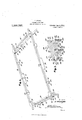
- Figure 1 is a top plan view of the device set up for use.
- Fig. 2 is a side elevation thereof.
- Fig. 3 is a perspective view of the frame of the device with the flexible covering removed.
- Fig. 4 is an inverted perspective view of a portion of the complete device with the leg members folded.
- Fig. 5 is a perspective view of the frame-work, with'the side portions thereof in their folded positions.
- FIG. 6 is a similar view of the frame-Work showing a further step inthe foldlng operation thereof, and, Fig. 7 1s a perspectlve View of p the frame-work completely folded.
- the device broadly consists of the fold-able frame 9 shown in Fig. 3 and a flexible covering' or mattress 10 that is adapted to be 1 permanently secured thereto at the time of manufacture.
- I lar. form having a projecting handle 11 at each corner thereof and being provided ad-
- the said frame. is rectangujacent each end with double leg members 12 if in the form of supporting yokes eachhav ingoppositely-arranged feet 13.
- the rectangular frame 9 is composed of'opposite side rails 14 terminating at each of their ends in corner portions 15,.the said handles 11 being formed integrally therewith-while the legs 12 are hinged to the inner sides of the corner portions 15 as at 16.
- the side rails 14 are provided centrally upon their under sides with blocks 17 pointed at their opposite ends 18 while the said rails and lower faces of the said lugs and whereby the opposite end portions of the rails 14 are hingedly connectedtogether.
- the end legs 12 being pivoted within the frame'9 are adapted for folding inwardly between the side rails '14 thereof as'best illustrated in Fig. 4 of the drawing.
- said frame 9 is provided with end bars 24 each'of which is severed adjacent its opposite endsas at 25 and the three portions of each bar thus formed are hingedly connected together by means of hinges 26 secured to the lower faces of the said bars at the points of severance thereof.
- the said legs l2 are each provided with'connecting bars 27 connecting the opposite sides 28 thereof, the
- said bars 27 being of substantially the same length as the frame bars 24 and being similarly transversely severed as at 29, the three portions of each of the bars 27 being connected together by means of suitable hinges 30 upon the outersides of the said bars 27.
- hinged end bars 24 and connecting bars 27 By means of this arrangement of hinged end bars 24 and connecting bars 27, it will be seen that the side rails 14 may be folded inwardly in contact with each other by folding the separate portions of the bars 24 and 27 together, such partial folding of the frame being best illustrated herein by Fig. 5 of the drawing.
- the handles 11 having outer curved cut-away portions or notches 31 provide end notches when the frame is so folded as shown in Fig.
- the notches 31 will receive and accommodate the tapered block ends 18 as best illustrated in Fig. 6, it being noted that the blocks 17 are of greater height than the hinged lugs 21 of the side rails.
- the aforementioned flexible covering 10 which forms the mattress or supporting member of the stretcher may be provided of any flexible material such as canvas and'is permanently secured to the side rails 1 1- and end members 24 by means of encircling side straps 32.
- the covering 10 is provided with substantially circular openings 33 at points adjacent the connecting bar hinges 30 and these openings accommodate the connecting bars so that the stretcher frame may be readily completely folded with the said covering 10 operatively attached thereto, it being understood that the folded over end portions, of the connecting bars 27 will slightly project through the openings 33 when the device is in its folded position.
- the structure therefore affords a serviceable stretcher that possesses the requisite strength for operative use while the same is capable of being quickly and easily folded into compact form whenever desired, it being seen that the inward positioning of the legs 12 when folded as well as the arrangement of the notch formations 31 and the block 17 received thereby forms a rigid interlocking arrangement when the complete structure is folded in its inoperative position.
- a rectangular stretcher frame comprising side rails and hinged end bars, tapered blocks centrally carried by the said rails and projecting lugs also carried by the same side thereof, the said side rails being transversely severed through the said blocks and lugs, hinged connections between the severed portions of the said blocks and lugs, and foldable sectional supporting legs arranged at the opposite ends of the said frame.
- a rectangular stretcher frame comprising side rails and hinged end bars, tapered blocks centrally carried by the said rails and projecting lugs also carried by the same side thereof, the said side rails being transversely severed through the said blocks and lugs, hinged connections between the severed portions of the said blocks and lugs, foldable sectional supporting legs arranged at the opposite ends of the said frame, the said blocks being of greater height than the said lugs, and terminal handles upon the said rails having cut-away outer portions adapted for the reception of the opposite ends of the said blocks when the device is in its folded formation.
- a stretcher comprising a rectangular frame having opposite side rails and end bars, yoke-shaped legs formed in hinged sections pivoted between the said rails, a flexible covering secured to the said rails and bars and provided with accommodating openings therein arranged adjacent the hinging points of the said legs, the said rails being formed in four substantially equal portions, hinged connections between the said rail portions, the said end bars being divided into three portions, and hinged connections between the said rail portions.
- a stretcher comprising a rectangular frame having side rails divided into four sections and end rails divided into three sections, hinges upon the lower side of the said frame connecting the said sections together, inwardly foldable leg yokes pivotally at tached adjacent the corners of the said frame and having connecting bars divided into three portions substantially corresponding to the portions of the said end bars of the frame, hinged connections between the said connecting bar portions, and a flexible covering carried by the said frame and pro vided with accommodating openings therethrough positioned adjacent the said hinges of the connecting bars when the device is in its folded position.
- a stretcher comprising a rectangular frame having side rails divided into four sections and end rails divided into three sections, hinges upon the lower side of the said frame connecting the said sections to-' gether, inwardly foldable leg yokes pivot ally attached adjacent the corners of the said frame and having connecting bars divided into three portions substantially corresponding to the portions of the said end bars of the frame, hinged connections between the said connecting bar portions, a flexible covering carried by the said frame and provided With accommodating openings therethrough positioned adjacent the said hinges of the connecting bars When the device is in its folded position, corner handles upon the said frame having cut-away portions upon their outersides cooperating in the formation of notches When the side rails JOHN WARGA.
Landscapes
- Health & Medical Sciences (AREA)
- Life Sciences & Earth Sciences (AREA)
- Animal Behavior & Ethology (AREA)
- General Health & Medical Sciences (AREA)
- Public Health (AREA)
- Veterinary Medicine (AREA)
- Mattresses And Other Support Structures For Chairs And Beds (AREA)
Description
J. WARGA.
FOLDING STRETCHER.
APPLICATION FILED SEPT. 9. 1915.
Patented Jan. 4, 1916.
' 3 sHEETs-sHEEI l.
Fig. 2.
COLUMBIA PLANODRAPH c0..wAsmNa'roN,n. c.
J. WARGA.
FOLDING STRETCHER.
APPL lCATl0N men SEPT. 9, 1915.
Patented Jan. 4, 1916.
3 SHEETSSHEET 2.
C MBIA FLANDURAPH COqVASHlNOTONrD. C
J. WARGA.
FOLDING STRETCHER.
APPLICATION FILED SEPT. 9, 1915.
Patented Jan. 4, 1916.
3 SHEETSSHEET 3.
cpLuMBlA PLANMRAPH C0 WASHINGTON, D. c.
* UNTTEED starts a ame JOHN WARGA, OF OHIO CITY, 01-110, ASSIGNOR OF ONE-HALF TO STEVE BUBENKO, OF OHIO-GITY ,.OHIO. j 1
FOLDING STRETCHER.
Specification of Letters Patent. Patented Jan. 4, 1 916.
Application filed September 9, 1915. Serial No. 49,700.
To all whom it may concern." I
Be it known that 1 JOHN VVARGA, a subject of the King of Hungary, residing at Ohio City, in the county, of Van Wert and State of Ohio, have invented certain new and useful Improvements in Folding Stretchers, of which the following is a specification.
This invention relates to certain new and useful improvements in folding stretchers.
The primary object of the device is the provision of a stretcher adapted for army and hospital use and which may be readily folded into compact form whenever desired as for storage purposes.
A further object of the invention is the provision of a foldable stretcher of the form embodying a frame and flexible mattress which is so constructed as to be readily folded and unfolded without removing the mattress from the frame.
A still further object is the provision of a foldable stretcher frame arranged for supporting a flexible covering and designed to allow the parts of the frame to interengage for accommodating the same, the covering being so arranged as topermit a fold ing of the frame without removal or injury to the covering. 7
With these general objects in view and others that will appear as the nature of the invention is better understood, the same consists in the novel construction, combination and arrangement of parts hereinafter more.
fully described, illustrated in the accompanying drawings, and then claimed.
In the drawings forming a part of this application and in which like designating characters refer to corresponding; parts throughout the several views, Figure 1 is a top plan view of the device set up for use.
Fig. 2 is a side elevation thereof. Fig. 3 is a perspective view of the frame of the device with the flexible covering removed. Fig. 4 is an inverted perspective view of a portion of the complete device with the leg members folded. Fig. 5 is a perspective view of the frame-work, with'the side portions thereof in their folded positions. Fig.
6 is a similar view of the frame-Work showing a further step inthe foldlng operation thereof, and, Fig. 7 1s a perspectlve View of p the frame-work completely folded.
Referring more in detail to the drawings, the device broadly consists of the fold-able frame 9 shown in Fig. 3 and a flexible covering' or mattress 10 that is adapted to be 1 permanently secured thereto at the time of manufacture. I lar. form having a projecting handle 11 at each corner thereof and being provided ad- The said frame. is rectangujacent each end with double leg members 12 if in the form of supporting yokes eachhav ingoppositely-arranged feet 13. The rectangular frame 9 is composed of'opposite side rails 14 terminating at each of their ends in corner portions 15,.the said handles 11 being formed integrally therewith-while the legs 12 are hinged to the inner sides of the corner portions 15 as at 16. The side rails 14 are provided centrally upon their under sides with blocks 17 pointed at their opposite ends 18 while the said rails and lower faces of the said lugs and whereby the opposite end portions of the rails 14 are hingedly connectedtogether.
The end legs 12 being pivoted within the frame'9 are adapted for folding inwardly between the side rails '14 thereof as'best illustrated in Fig. 4 of the drawing. The
said frame 9 is provided with end bars 24 each'of which is severed adjacent its opposite endsas at 25 and the three portions of each bar thus formed are hingedly connected together by means of hinges 26 secured to the lower faces of the said bars at the points of severance thereof. The said legs l2are each provided with'connecting bars 27 connecting the opposite sides 28 thereof, the
said bars 27 being of substantially the same length as the frame bars 24 and being similarly transversely severed as at 29, the three portions of each of the bars 27 being connected together by means of suitable hinges 30 upon the outersides of the said bars 27. By means of this arrangement of hinged end bars 24 and connecting bars 27, it will be seen that the side rails 14 may be folded inwardly in contact with each other by folding the separate portions of the bars 24 and 27 together, such partial folding of the frame being best illustrated herein by Fig. 5 of the drawing. The handles 11 having outer curved cut-away portions or notches 31 provide end notches when the frame is so folded as shown in Fig. 5 and upon fold ing together the portions of the end members of the rails 14 by moving the same upon their hinges 23, the notches 31 will receive and accommodate the tapered block ends 18 as best illustrated in Fig. 6, it being noted that the blocks 17 are of greater height than the hinged lugs 21 of the side rails.
lVhen the frame is partially folded as shown in Fig. 6, it will be seen that the frame will then be in a position to be fur ther folded by moving the end portions thereof upon the connecting hinges 20 and whereupon the frame will be completely folded, assuming thecompact form illustrated in Fig. 7. The aforementioned flexible covering 10 which forms the mattress or supporting member of the stretcher may be provided of any flexible material such as canvas and'is permanently secured to the side rails 1 1- and end members 24 by means of encircling side straps 32. The covering 10 is provided with substantially circular openings 33 at points adjacent the connecting bar hinges 30 and these openings accommodate the connecting bars so that the stretcher frame may be readily completely folded with the said covering 10 operatively attached thereto, it being understood that the folded over end portions, of the connecting bars 27 will slightly project through the openings 33 when the device is in its folded position. For affording additional strength at the hinged points hereinbefore noted, it is desirable to complementally form the adjacent ends of the members which are hinged together and such formation as herein carried out by means of tongues 3% adapted to be received within receiving slots 35 upon the end of the oppositely-arranged cooperating member. The structure therefore affords a serviceable stretcher that possesses the requisite strength for operative use while the same is capable of being quickly and easily folded into compact form whenever desired, it being seen that the inward positioning of the legs 12 when folded as well as the arrangement of the notch formations 31 and the block 17 received thereby forms a rigid interlocking arrangement when the complete structure is folded in its inoperative position.
lVhile the form of the invention herein shown and described is what is believed to be the preferred embodiment thereof, it is nevertheless to be understood that various forms, modifications and arrangements of the parts may be made without departing from the spirit and scope of the invention as claimed.
W hat I claim as new is I 1. A rectangular stretcher frame comprising side rails and hinged end bars, tapered blocks centrally carried by the said rails and projecting lugs also carried by the same side thereof, the said side rails being transversely severed through the said blocks and lugs, hinged connections between the severed portions of the said blocks and lugs, and foldable sectional supporting legs arranged at the opposite ends of the said frame.
2. A rectangular stretcher frame comprising side rails and hinged end bars, tapered blocks centrally carried by the said rails and projecting lugs also carried by the same side thereof, the said side rails being transversely severed through the said blocks and lugs, hinged connections between the severed portions of the said blocks and lugs, foldable sectional supporting legs arranged at the opposite ends of the said frame, the said blocks being of greater height than the said lugs, and terminal handles upon the said rails having cut-away outer portions adapted for the reception of the opposite ends of the said blocks when the device is in its folded formation.
3. A stretcher comprising a rectangular frame having opposite side rails and end bars, yoke-shaped legs formed in hinged sections pivoted between the said rails, a flexible covering secured to the said rails and bars and provided with accommodating openings therein arranged adjacent the hinging points of the said legs, the said rails being formed in four substantially equal portions, hinged connections between the said rail portions, the said end bars being divided into three portions, and hinged connections between the said rail portions.
4. A stretcher comprising a rectangular frame having side rails divided into four sections and end rails divided into three sections, hinges upon the lower side of the said frame connecting the said sections together, inwardly foldable leg yokes pivotally at tached adjacent the corners of the said frame and having connecting bars divided into three portions substantially corresponding to the portions of the said end bars of the frame, hinged connections between the said connecting bar portions, and a flexible covering carried by the said frame and pro vided with accommodating openings therethrough positioned adjacent the said hinges of the connecting bars when the device is in its folded position.
5. A stretcher comprising a rectangular frame having side rails divided into four sections and end rails divided into three sections, hinges upon the lower side of the said frame connecting the said sections to-' gether, inwardly foldable leg yokes pivot ally attached adjacent the corners of the said frame and having connecting bars divided into three portions substantially corresponding to the portions of the said end bars of the frame, hinged connections between the said connecting bar portions, a flexible covering carried by the said frame and provided With accommodating openings therethrough positioned adjacent the said hinges of the connecting bars When the device is in its folded position, corner handles upon the said frame having cut-away portions upon their outersides cooperating in the formation of notches When the side rails JOHN WARGA.
Copies of this patent may be obtained for five cents each, by addressing" the Commissioner of Patents, Washington, D. G.
Priority Applications (1)
| Application Number | Priority Date | Filing Date | Title |
|---|---|---|---|
| US4970015A US1166727A (en) | 1915-09-09 | 1915-09-09 | Folding stretcher. |
Applications Claiming Priority (1)
| Application Number | Priority Date | Filing Date | Title |
|---|---|---|---|
| US4970015A US1166727A (en) | 1915-09-09 | 1915-09-09 | Folding stretcher. |
Publications (1)
| Publication Number | Publication Date |
|---|---|
| US1166727A true US1166727A (en) | 1916-01-04 |
Family
ID=3234748
Family Applications (1)
| Application Number | Title | Priority Date | Filing Date |
|---|---|---|---|
| US4970015A Expired - Lifetime US1166727A (en) | 1915-09-09 | 1915-09-09 | Folding stretcher. |
Country Status (1)
| Country | Link |
|---|---|
| US (1) | US1166727A (en) |
-
1915
- 1915-09-09 US US4970015A patent/US1166727A/en not_active Expired - Lifetime
Similar Documents
| Publication | Publication Date | Title |
|---|---|---|
| US615476A (en) | Folding stool | |
| US769354A (en) | Table. | |
| US927738A (en) | Mosquito-bar frame. | |
| US1072060A (en) | Knockdown table. | |
| US1166727A (en) | Folding stretcher. | |
| US1044128A (en) | Adjustable folding hurdle. | |
| US1205186A (en) | Collapsible stretcher. | |
| US244217A (en) | Folding cradle | |
| US952214A (en) | Collapsible cot. | |
| US1229537A (en) | Foldable hammock-stand. | |
| US708869A (en) | Folding cot. | |
| US1023048A (en) | Covered folding cot. | |
| US505409A (en) | morrell | |
| US653762A (en) | Cooling-board. | |
| US627100A (en) | Combination tent-frame and cot | |
| US1136174A (en) | Foldable stretcher. | |
| US1057545A (en) | Collapsible table. | |
| US709332A (en) | Folding stretcher or cot. | |
| US1269641A (en) | Collapsible cot. | |
| US1146802A (en) | Foldable stretcher. | |
| US1021094A (en) | Combination step-ladder and bench. | |
| US556833A (en) | Cot or bed frame | |
| US921466A (en) | Convertible folding couch. | |
| US1120480A (en) | Combined bed and trunk. | |
| US318779A (en) | James c |