US11511368B2 - Electrically conductive tip member and method for producing the same - Google Patents
Electrically conductive tip member and method for producing the same Download PDFInfo
- Publication number
- US11511368B2 US11511368B2 US16/884,502 US202016884502A US11511368B2 US 11511368 B2 US11511368 B2 US 11511368B2 US 202016884502 A US202016884502 A US 202016884502A US 11511368 B2 US11511368 B2 US 11511368B2
- Authority
- US
- United States
- Prior art keywords
- periphery portion
- inner periphery
- phase
- electrically conductive
- raw material
- Prior art date
- Legal status (The legal status is an assumption and is not a legal conclusion. Google has not performed a legal analysis and makes no representation as to the accuracy of the status listed.)
- Active, expires
Links
- 238000004519 manufacturing process Methods 0.000 title claims description 23
- 229910017985 Cu—Zr Inorganic materials 0.000 claims abstract description 70
- 229910045601 alloy Inorganic materials 0.000 claims abstract description 63
- 239000000956 alloy Substances 0.000 claims abstract description 63
- 239000000203 mixture Substances 0.000 claims abstract description 44
- 239000000843 powder Substances 0.000 claims description 114
- 239000002994 raw material Substances 0.000 claims description 51
- 238000002490 spark plasma sintering Methods 0.000 claims description 33
- 238000000034 method Methods 0.000 claims description 23
- 238000005245 sintering Methods 0.000 claims description 21
- 229910000568 zirconium hydride Inorganic materials 0.000 claims description 21
- 238000003466 welding Methods 0.000 claims description 12
- 230000005496 eutectics Effects 0.000 claims description 11
- 230000002093 peripheral effect Effects 0.000 claims 10
- 150000001875 compounds Chemical class 0.000 abstract description 57
- 239000011159 matrix material Substances 0.000 abstract description 22
- 229910052751 metal Inorganic materials 0.000 abstract description 13
- 239000002184 metal Substances 0.000 abstract description 13
- 239000010949 copper Substances 0.000 description 102
- 239000002245 particle Substances 0.000 description 48
- 229910000881 Cu alloy Inorganic materials 0.000 description 21
- 238000004458 analytical method Methods 0.000 description 20
- 238000005259 measurement Methods 0.000 description 20
- RYGMFSIKBFXOCR-UHFFFAOYSA-N Copper Chemical compound [Cu] RYGMFSIKBFXOCR-UHFFFAOYSA-N 0.000 description 18
- 239000000463 material Substances 0.000 description 16
- 238000010298 pulverizing process Methods 0.000 description 11
- 229910052802 copper Inorganic materials 0.000 description 10
- 238000009792 diffusion process Methods 0.000 description 8
- 238000006243 chemical reaction Methods 0.000 description 7
- 238000002156 mixing Methods 0.000 description 6
- 238000005192 partition Methods 0.000 description 6
- 238000002441 X-ray diffraction Methods 0.000 description 5
- QVGXLLKOCUKJST-UHFFFAOYSA-N atomic oxygen Chemical compound [O] QVGXLLKOCUKJST-UHFFFAOYSA-N 0.000 description 5
- 239000013078 crystal Substances 0.000 description 5
- 239000001301 oxygen Substances 0.000 description 5
- 229910052760 oxygen Inorganic materials 0.000 description 5
- 102220043159 rs587780996 Human genes 0.000 description 5
- IHCCLXNEEPMSIO-UHFFFAOYSA-N 2-[4-[2-(2,3-dihydro-1H-inden-2-ylamino)pyrimidin-5-yl]piperidin-1-yl]-1-(2,4,6,7-tetrahydrotriazolo[4,5-c]pyridin-5-yl)ethanone Chemical compound C1C(CC2=CC=CC=C12)NC1=NC=C(C=N1)C1CCN(CC1)CC(=O)N1CC2=C(CC1)NN=N2 IHCCLXNEEPMSIO-UHFFFAOYSA-N 0.000 description 4
- 229910017805 Cu—Be—Co Inorganic materials 0.000 description 4
- MCMNRKCIXSYSNV-UHFFFAOYSA-N Zirconium dioxide Chemical compound O=[Zr]=O MCMNRKCIXSYSNV-UHFFFAOYSA-N 0.000 description 4
- 230000000052 comparative effect Effects 0.000 description 4
- 238000009826 distribution Methods 0.000 description 4
- 238000007373 indentation Methods 0.000 description 4
- 238000001878 scanning electron micrograph Methods 0.000 description 4
- 239000010959 steel Substances 0.000 description 4
- NIPNSKYNPDTRPC-UHFFFAOYSA-N N-[2-oxo-2-(2,4,6,7-tetrahydrotriazolo[4,5-c]pyridin-5-yl)ethyl]-2-[[3-(trifluoromethoxy)phenyl]methylamino]pyrimidine-5-carboxamide Chemical compound O=C(CNC(=O)C=1C=NC(=NC=1)NCC1=CC(=CC=C1)OC(F)(F)F)N1CC2=C(CC1)NN=N2 NIPNSKYNPDTRPC-UHFFFAOYSA-N 0.000 description 3
- 229910000831 Steel Inorganic materials 0.000 description 3
- 230000001133 acceleration Effects 0.000 description 3
- 230000000903 blocking effect Effects 0.000 description 3
- 239000011651 chromium Substances 0.000 description 3
- 239000002131 composite material Substances 0.000 description 3
- 238000005516 engineering process Methods 0.000 description 3
- 239000010419 fine particle Substances 0.000 description 3
- 238000002844 melting Methods 0.000 description 3
- 230000008018 melting Effects 0.000 description 3
- 150000002739 metals Chemical class 0.000 description 3
- 229910000838 Al alloy Inorganic materials 0.000 description 2
- XKRFYHLGVUSROY-UHFFFAOYSA-N Argon Chemical compound [Ar] XKRFYHLGVUSROY-UHFFFAOYSA-N 0.000 description 2
- IJGRMHOSHXDMSA-UHFFFAOYSA-N Atomic nitrogen Chemical compound N#N IJGRMHOSHXDMSA-UHFFFAOYSA-N 0.000 description 2
- 229910017526 Cu-Cr-Zr Inorganic materials 0.000 description 2
- 229910017813 Cu—Cr Inorganic materials 0.000 description 2
- 229910017810 Cu—Cr—Zr Inorganic materials 0.000 description 2
- 229910052581 Si3N4 Inorganic materials 0.000 description 2
- VYPSYNLAJGMNEJ-UHFFFAOYSA-N Silicium dioxide Chemical compound O=[Si]=O VYPSYNLAJGMNEJ-UHFFFAOYSA-N 0.000 description 2
- 229910001093 Zr alloy Inorganic materials 0.000 description 2
- 229910052782 aluminium Inorganic materials 0.000 description 2
- PNEYBMLMFCGWSK-UHFFFAOYSA-N aluminium oxide Inorganic materials [O-2].[O-2].[O-2].[Al+3].[Al+3] PNEYBMLMFCGWSK-UHFFFAOYSA-N 0.000 description 2
- 229910052790 beryllium Inorganic materials 0.000 description 2
- 229910052804 chromium Inorganic materials 0.000 description 2
- 239000011362 coarse particle Substances 0.000 description 2
- 230000001186 cumulative effect Effects 0.000 description 2
- 230000007423 decrease Effects 0.000 description 2
- 238000002003 electron diffraction Methods 0.000 description 2
- 238000011156 evaluation Methods 0.000 description 2
- 230000005284 excitation Effects 0.000 description 2
- 238000000227 grinding Methods 0.000 description 2
- 229910052735 hafnium Inorganic materials 0.000 description 2
- 229910052742 iron Inorganic materials 0.000 description 2
- BWHLPLXXIDYSNW-UHFFFAOYSA-N ketorolac tromethamine Chemical compound OCC(N)(CO)CO.OC(=O)C1CCN2C1=CC=C2C(=O)C1=CC=CC=C1 BWHLPLXXIDYSNW-UHFFFAOYSA-N 0.000 description 2
- 229910052745 lead Inorganic materials 0.000 description 2
- 229910052749 magnesium Inorganic materials 0.000 description 2
- 229910052748 manganese Inorganic materials 0.000 description 2
- 229910052759 nickel Inorganic materials 0.000 description 2
- 229910052758 niobium Inorganic materials 0.000 description 2
- 230000010355 oscillation Effects 0.000 description 2
- 229910052698 phosphorus Inorganic materials 0.000 description 2
- 229910052710 silicon Inorganic materials 0.000 description 2
- HQVNEWCFYHHQES-UHFFFAOYSA-N silicon nitride Chemical compound N12[Si]34N5[Si]62N3[Si]51N64 HQVNEWCFYHHQES-UHFFFAOYSA-N 0.000 description 2
- 229910001220 stainless steel Inorganic materials 0.000 description 2
- 238000012360 testing method Methods 0.000 description 2
- 229910052718 tin Inorganic materials 0.000 description 2
- 229910052719 titanium Inorganic materials 0.000 description 2
- WFKWXMTUELFFGS-UHFFFAOYSA-N tungsten Chemical compound [W] WFKWXMTUELFFGS-UHFFFAOYSA-N 0.000 description 2
- 229910052721 tungsten Inorganic materials 0.000 description 2
- 239000010937 tungsten Substances 0.000 description 2
- 229910052725 zinc Inorganic materials 0.000 description 2
- 229910052726 zirconium Inorganic materials 0.000 description 2
- 229910000851 Alloy steel Inorganic materials 0.000 description 1
- 229910000967 As alloy Inorganic materials 0.000 description 1
- -1 Cu5Zr) phases Chemical class 0.000 description 1
- 229910017060 Fe Cr Inorganic materials 0.000 description 1
- 229910002544 Fe-Cr Inorganic materials 0.000 description 1
- 229910001111 Fine metal Inorganic materials 0.000 description 1
- 239000004831 Hot glue Substances 0.000 description 1
- 229910009043 WC-Co Inorganic materials 0.000 description 1
- 238000002679 ablation Methods 0.000 description 1
- 229910052786 argon Inorganic materials 0.000 description 1
- 230000005540 biological transmission Effects 0.000 description 1
- 238000000369 bright-field scanning transmission electron microscopy Methods 0.000 description 1
- UPHIPHFJVNKLMR-UHFFFAOYSA-N chromium iron Chemical compound [Cr].[Fe] UPHIPHFJVNKLMR-UHFFFAOYSA-N 0.000 description 1
- 238000005097 cold rolling Methods 0.000 description 1
- 238000011109 contamination Methods 0.000 description 1
- 239000002826 coolant Substances 0.000 description 1
- 238000001816 cooling Methods 0.000 description 1
- 229910052593 corundum Inorganic materials 0.000 description 1
- 238000013461 design Methods 0.000 description 1
- 238000007865 diluting Methods 0.000 description 1
- 230000005611 electricity Effects 0.000 description 1
- 239000005350 fused silica glass Substances 0.000 description 1
- 238000009689 gas atomisation Methods 0.000 description 1
- 230000005484 gravity Effects 0.000 description 1
- 230000017525 heat dissipation Effects 0.000 description 1
- 238000010438 heat treatment Methods 0.000 description 1
- 238000000731 high angular annular dark-field scanning transmission electron microscopy Methods 0.000 description 1
- 239000000155 melt Substances 0.000 description 1
- 229910052757 nitrogen Inorganic materials 0.000 description 1
- 239000011148 porous material Substances 0.000 description 1
- 230000002265 prevention Effects 0.000 description 1
- 238000012545 processing Methods 0.000 description 1
- 238000000992 sputter etching Methods 0.000 description 1
- 239000010935 stainless steel Substances 0.000 description 1
- 239000007858 starting material Substances 0.000 description 1
- 238000010998 test method Methods 0.000 description 1
- 238000012546 transfer Methods 0.000 description 1
- XLYOFNOQVPJJNP-UHFFFAOYSA-N water Substances O XLYOFNOQVPJJNP-UHFFFAOYSA-N 0.000 description 1
- 229910001845 yogo sapphire Inorganic materials 0.000 description 1
Images


Classifications
-
- C—CHEMISTRY; METALLURGY
- C22—METALLURGY; FERROUS OR NON-FERROUS ALLOYS; TREATMENT OF ALLOYS OR NON-FERROUS METALS
- C22C—ALLOYS
- C22C1/00—Making non-ferrous alloys
- C22C1/04—Making non-ferrous alloys by powder metallurgy
- C22C1/0425—Copper-based alloys
-
- B—PERFORMING OPERATIONS; TRANSPORTING
- B22—CASTING; POWDER METALLURGY
- B22F—WORKING METALLIC POWDER; MANUFACTURE OF ARTICLES FROM METALLIC POWDER; MAKING METALLIC POWDER; APPARATUS OR DEVICES SPECIALLY ADAPTED FOR METALLIC POWDER
- B22F1/00—Metallic powder; Treatment of metallic powder, e.g. to facilitate working or to improve properties
- B22F1/17—Metallic particles coated with metal
-
- B—PERFORMING OPERATIONS; TRANSPORTING
- B22—CASTING; POWDER METALLURGY
- B22F—WORKING METALLIC POWDER; MANUFACTURE OF ARTICLES FROM METALLIC POWDER; MAKING METALLIC POWDER; APPARATUS OR DEVICES SPECIALLY ADAPTED FOR METALLIC POWDER
- B22F3/00—Manufacture of workpieces or articles from metallic powder characterised by the manner of compacting or sintering; Apparatus specially adapted therefor ; Presses and furnaces
- B22F3/10—Sintering only
- B22F3/105—Sintering only by using electric current other than for infrared radiant energy, laser radiation or plasma ; by ultrasonic bonding
-
- B—PERFORMING OPERATIONS; TRANSPORTING
- B22—CASTING; POWDER METALLURGY
- B22F—WORKING METALLIC POWDER; MANUFACTURE OF ARTICLES FROM METALLIC POWDER; MAKING METALLIC POWDER; APPARATUS OR DEVICES SPECIALLY ADAPTED FOR METALLIC POWDER
- B22F3/00—Manufacture of workpieces or articles from metallic powder characterised by the manner of compacting or sintering; Apparatus specially adapted therefor ; Presses and furnaces
- B22F3/12—Both compacting and sintering
- B22F3/14—Both compacting and sintering simultaneously
-
- B—PERFORMING OPERATIONS; TRANSPORTING
- B22—CASTING; POWDER METALLURGY
- B22F—WORKING METALLIC POWDER; MANUFACTURE OF ARTICLES FROM METALLIC POWDER; MAKING METALLIC POWDER; APPARATUS OR DEVICES SPECIALLY ADAPTED FOR METALLIC POWDER
- B22F7/00—Manufacture of composite layers, workpieces, or articles, comprising metallic powder, by sintering the powder, with or without compacting wherein at least one part is obtained by sintering or compression
- B22F7/06—Manufacture of composite layers, workpieces, or articles, comprising metallic powder, by sintering the powder, with or without compacting wherein at least one part is obtained by sintering or compression of composite workpieces or articles from parts, e.g. to form tipped tools
-
- B—PERFORMING OPERATIONS; TRANSPORTING
- B23—MACHINE TOOLS; METAL-WORKING NOT OTHERWISE PROVIDED FOR
- B23K—SOLDERING OR UNSOLDERING; WELDING; CLADDING OR PLATING BY SOLDERING OR WELDING; CUTTING BY APPLYING HEAT LOCALLY, e.g. FLAME CUTTING; WORKING BY LASER BEAM
- B23K11/00—Resistance welding; Severing by resistance heating
- B23K11/10—Spot welding; Stitch welding
- B23K11/11—Spot welding
-
- B—PERFORMING OPERATIONS; TRANSPORTING
- B23—MACHINE TOOLS; METAL-WORKING NOT OTHERWISE PROVIDED FOR
- B23K—SOLDERING OR UNSOLDERING; WELDING; CLADDING OR PLATING BY SOLDERING OR WELDING; CUTTING BY APPLYING HEAT LOCALLY, e.g. FLAME CUTTING; WORKING BY LASER BEAM
- B23K11/00—Resistance welding; Severing by resistance heating
- B23K11/30—Features relating to electrodes
- B23K11/3009—Pressure electrodes
-
- B—PERFORMING OPERATIONS; TRANSPORTING
- B23—MACHINE TOOLS; METAL-WORKING NOT OTHERWISE PROVIDED FOR
- B23K—SOLDERING OR UNSOLDERING; WELDING; CLADDING OR PLATING BY SOLDERING OR WELDING; CUTTING BY APPLYING HEAT LOCALLY, e.g. FLAME CUTTING; WORKING BY LASER BEAM
- B23K35/00—Rods, electrodes, materials, or media, for use in soldering, welding, or cutting
- B23K35/02—Rods, electrodes, materials, or media, for use in soldering, welding, or cutting characterised by mechanical features, e.g. shape
- B23K35/0205—Non-consumable electrodes; C-electrodes
-
- B—PERFORMING OPERATIONS; TRANSPORTING
- B23—MACHINE TOOLS; METAL-WORKING NOT OTHERWISE PROVIDED FOR
- B23K—SOLDERING OR UNSOLDERING; WELDING; CLADDING OR PLATING BY SOLDERING OR WELDING; CUTTING BY APPLYING HEAT LOCALLY, e.g. FLAME CUTTING; WORKING BY LASER BEAM
- B23K35/00—Rods, electrodes, materials, or media, for use in soldering, welding, or cutting
- B23K35/40—Making wire or rods for soldering or welding
- B23K35/402—Non-consumable electrodes; C-electrodes
-
- C—CHEMISTRY; METALLURGY
- C22—METALLURGY; FERROUS OR NON-FERROUS ALLOYS; TREATMENT OF ALLOYS OR NON-FERROUS METALS
- C22C—ALLOYS
- C22C9/00—Alloys based on copper
-
- B—PERFORMING OPERATIONS; TRANSPORTING
- B22—CASTING; POWDER METALLURGY
- B22F—WORKING METALLIC POWDER; MANUFACTURE OF ARTICLES FROM METALLIC POWDER; MAKING METALLIC POWDER; APPARATUS OR DEVICES SPECIALLY ADAPTED FOR METALLIC POWDER
- B22F3/00—Manufacture of workpieces or articles from metallic powder characterised by the manner of compacting or sintering; Apparatus specially adapted therefor ; Presses and furnaces
- B22F3/10—Sintering only
- B22F3/105—Sintering only by using electric current other than for infrared radiant energy, laser radiation or plasma ; by ultrasonic bonding
- B22F2003/1051—Sintering only by using electric current other than for infrared radiant energy, laser radiation or plasma ; by ultrasonic bonding by electric discharge
-
- B—PERFORMING OPERATIONS; TRANSPORTING
- B22—CASTING; POWDER METALLURGY
- B22F—WORKING METALLIC POWDER; MANUFACTURE OF ARTICLES FROM METALLIC POWDER; MAKING METALLIC POWDER; APPARATUS OR DEVICES SPECIALLY ADAPTED FOR METALLIC POWDER
- B22F2207/00—Aspects of the compositions, gradients
- B22F2207/01—Composition gradients
- B22F2207/07—Particles with core-rim gradient
-
- B—PERFORMING OPERATIONS; TRANSPORTING
- B22—CASTING; POWDER METALLURGY
- B22F—WORKING METALLIC POWDER; MANUFACTURE OF ARTICLES FROM METALLIC POWDER; MAKING METALLIC POWDER; APPARATUS OR DEVICES SPECIALLY ADAPTED FOR METALLIC POWDER
- B22F2301/00—Metallic composition of the powder or its coating
- B22F2301/10—Copper
-
- B—PERFORMING OPERATIONS; TRANSPORTING
- B22—CASTING; POWDER METALLURGY
- B22F—WORKING METALLIC POWDER; MANUFACTURE OF ARTICLES FROM METALLIC POWDER; MAKING METALLIC POWDER; APPARATUS OR DEVICES SPECIALLY ADAPTED FOR METALLIC POWDER
- B22F2998/00—Supplementary information concerning processes or compositions relating to powder metallurgy
- B22F2998/10—Processes characterised by the sequence of their steps
-
- B—PERFORMING OPERATIONS; TRANSPORTING
- B22—CASTING; POWDER METALLURGY
- B22F—WORKING METALLIC POWDER; MANUFACTURE OF ARTICLES FROM METALLIC POWDER; MAKING METALLIC POWDER; APPARATUS OR DEVICES SPECIALLY ADAPTED FOR METALLIC POWDER
- B22F2999/00—Aspects linked to processes or compositions used in powder metallurgy
-
- B—PERFORMING OPERATIONS; TRANSPORTING
- B22—CASTING; POWDER METALLURGY
- B22F—WORKING METALLIC POWDER; MANUFACTURE OF ARTICLES FROM METALLIC POWDER; MAKING METALLIC POWDER; APPARATUS OR DEVICES SPECIALLY ADAPTED FOR METALLIC POWDER
- B22F3/00—Manufacture of workpieces or articles from metallic powder characterised by the manner of compacting or sintering; Apparatus specially adapted therefor ; Presses and furnaces
- B22F3/004—Filling molds with powder
-
- B—PERFORMING OPERATIONS; TRANSPORTING
- B23—MACHINE TOOLS; METAL-WORKING NOT OTHERWISE PROVIDED FOR
- B23K—SOLDERING OR UNSOLDERING; WELDING; CLADDING OR PLATING BY SOLDERING OR WELDING; CUTTING BY APPLYING HEAT LOCALLY, e.g. FLAME CUTTING; WORKING BY LASER BEAM
- B23K2103/00—Materials to be soldered, welded or cut
- B23K2103/02—Iron or ferrous alloys
- B23K2103/04—Steel or steel alloys
-
- C—CHEMISTRY; METALLURGY
- C22—METALLURGY; FERROUS OR NON-FERROUS ALLOYS; TREATMENT OF ALLOYS OR NON-FERROUS METALS
- C22C—ALLOYS
- C22C1/00—Making non-ferrous alloys
- C22C1/04—Making non-ferrous alloys by powder metallurgy
- C22C1/045—Alloys based on refractory metals
- C22C1/0458—Alloys based on titanium, zirconium or hafnium
Definitions
- the present description discloses an electrically conductive tip member and a method for producing the same.
- Known conventional electrically conductive tip members used as welding electrodes are used to hold workpieces such as steel or aluminum alloy bodies and cause a large current to flow through the pressed workpieces in a short time in a pressured state to thereby melt and weld their contact interface.
- a heat transfer interference portion having lower thermal conductivity than its surrounding area is disposed in a central region of a holding surface of each of the facing electrodes (see, for example, PTL 1).
- a tip electrode formed of steel composed mainly of tungsten is embedded in a forward end of a shank (see, for example, PTL 2). It is stated that, with this welding electrode, high-tension coated steel sheets can be resistance-welded.
- the electrode body is formed of Cu or a Cu alloy, and the central region is formed of tungsten. Since different metals with different sintering temperatures are used, many steps are necessary to produce the electrode in some cases. Moreover, since each of these tip electrodes is formed using different metals, an interface may be formed between these metals. This has led to the desire for a novel electrically conductive tip member that can be produced using a simple production process and has no interface between its components.
- the invention disclosed in the present description has been made in view of the foregoing circumstances, and it is a principal object to provide a novel electrically conductive tip member having higher electrical conductivity and higher strength and a method for producing the electrically conductive tip member.
- an electrically conductive tip member disclosed in the present description includes:
- an inner periphery portion including a Cu matrix phase and a second phase that is dispersed in the Cu matrix phase and contains a Cu—Zr-based compound, the inner periphery portion having an alloy composition of Cu-xZr (where x is the atomic percentage of Zr and satisfies 0.5 ⁇ x ⁇ 16.7); and
- an outer periphery portion that is present on an outer circumferential side of the inner periphery portion, made of a metal containing Cu, and has higher electrical conductivity than the inner periphery portion.
- An electrically conductive tip member production method disclosed in the present description is a method for producing an electrically conductive tip member including an inner periphery portion and an outer periphery portion that is present on an outer circumferential side of the inner periphery portion and has higher electrical conductivity than the inner periphery portion,
- the method including a sintering step of: disposing a raw material of the outer periphery portion, the raw material containing Cu and having higher electrical conductivity than the inner periphery portion; disposing a raw material powder for the inner periphery portion on an inner circumferential side of the raw material of the outer periphery portion, the raw material powder having an alloy composition of Cu-xZr (where x is the atomic percentage of Zr and satisfies 0.5 ⁇ x ⁇ 16.7) obtained using a powder containing Cu and a Cu—Zr master alloy or a powder containing Cu and ZrH 2 ; pressurizing and holding the raw material powder in a prescribed pressure range at a prescribed temperature lower than a eutectic point temperature; and subjecting the raw material powder to spark plasma sintering.
- a sintering step of: disposing a raw material of the outer periphery portion, the raw material containing Cu and having higher electrical conductivity than the inner periphery portion; disposing a raw material
- the electrically conductive tip member and the method for producing the same disclosed in the present description can provide a novel product having higher electrical conductivity and also higher strength.
- the reason for this may be as follows.
- the outer periphery portion is formed of the metal containing Cu and having high electrical conductivity
- the inner periphery portion is formed of a high-strength material including the Cu matrix phase and the second phase containing the Cu—Zr-based compound. It is therefore inferred that the outer side provides the high electrical conductivity and the inner side provides the high strength and high hardness.
- the outer periphery portion and the inner periphery portion are formed of similar Cu-based materials, an unwanted interface, for example, is unlikely to be formed therebetween, so that problems are less likely to occur than in an electrically conductive tip member having an interface.
- some metal element powders are highly reactive.
- Zr powder is highly reactive with oxygen, so that extreme care is required when it is used as a raw material powder in air.
- Cu—Zr master alloy powder e.g., a Cu-50 mass % Zr master alloy
- ZrH 2 powder are relatively stable and can be handled with ease even in air.
- An inner periphery portion containing the Cu—Zr-based compound can be produced using relatively simple treatment in which any of these raw material powders is subjected to spark plasma sintering. Moreover, since the outer periphery portion and the inner periphery portion are formed of the Cu-based materials, their sintering temperatures do not differ significantly. This is advantageous in that the objective product can be obtained by one spark plasma sintering (SPS) operation.
- SPS spark plasma sintering
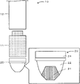
- FIG. 1 is an illustration showing an example of a welding arm 10 including a tip electrode 20 .
- FIGS. 2A and 2B show illustrations of other tip electrodes 20 B and 20 C.
- FIGS. 3A to 3C show SEM images of raw material powders in Experimental Examples 1-3, 3-3, and 4-3.
- FIG. 4 shows the results of X-ray diffraction measurement for raw material powders in Experimental Examples 1-3, 3-3, and 4-3.
- FIGS. 5A to 5D show SEM-BE images of cross sections in Experimental Examples 1 to 4.
- FIG. 6 shows the results of measurement of the electrical conductivity of copper alloys in Experimental Examples 1 to 4.
- FIGS. 7A and 7B show photographs of an electrically conductive tip member in Example 1.
- FIGS. 8A to 8D show SEM photographs of cross sections of boundary portions between an outer periphery portion and an inner periphery portion in Example 1.
- FIGS. 9A to 9F show enlarged SEM photographs of boundary portions in Example 1 and the results of elementary analysis.
- FIGS. 10A and 10B show photographs of an electrically conductive tip member in Example 2.
- FIGS. 11A to 11F show an enlarged SEM photograph of a boundary portion in Example 2 and the results of elementary analysis.
- FIGS. 12A to 12D show SEM photographs of cross sections of boundary portions between an outer periphery portion and an inner periphery portion in Example 5.
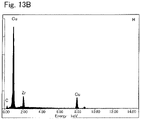
- FIGS. 13A to 13C show an enlarged SEM photograph of a boundary portion in Example 5 and the results of elementary analysis.
- FIGS. 14A and 14B show an SEM photograph of a cross section of a boundary portion between an outer periphery portion and an inner periphery portion in Example 6.
- FIGS. 15A to 15E show an enlarged SEM photograph of a boundary portion in Example 6 and the results of elementary analysis.
- FIG. 1 is an illustration showing an example of a welding arm 10 including a tip electrode 20 that is an example of an electrically conductive tip member in an embodiment.
- This welding arm 10 is used to weld workpieces such as steel sheets or aluminum alloy sheets and may be used, for example, for spot welding.
- the welding arm 10 includes: the tip electrode 20 that comes into contact with a workpiece and melts the workpiece; a holder 12 that is disposed in a base portion of a welding robot and receives electricity; and a shank 11 that is interposed between the tip electrode 20 and the holder 12 to supply electric power to the tip electrode 20 and hold the tip electrode 20 .
- the shank 11 is a member required to have high electrical conductivity, high strength, high hardness, etc.
- the shank 11 has an unillustrated connection portion to which the tip electrode 20 is connected and an unillustrated attachment portion attached to the holder 12 .
- the shank 11 may be formed of, for example, a Cu—Be—Co-based alloy.
- the shank 11 may have a hollow shape in which an internal space serving as a coolant channel such as a water cooling pipe is formed.
- the holder 12 is a member required to have high heat dissipation ability, high strength, high hardness, etc. and may be formed of, for example, a Cu—Ni—Be-based alloy.
- the tip electrode 20 is a member required to have electrical conductivity, high thermal stability, and hardness.
- the tip electrode 20 includes an inner periphery portion 21 , an outer periphery portion 22 , and a connection portion 24 .
- the connection portion 24 (socket) of the tip electrode 20 is required to have high hardness and may be formed of, for example, a Cu—Be—Co-based alloy.
- the inner periphery portion 21 may have higher hardness and mechanical strength (such as tensile strength) than the outer periphery portion 22 .
- the inner periphery portion 21 includes a Cu matrix phase and a second phase dispersed in the Cu matrix phase and containing a Cu—Zr-based compound and has an alloy composition of Cu-xZr (where x is the atomic percentage of Zr and satisfies 0.5 ⁇ x ⁇ 16.7).
- the inner periphery portion 21 has electrical conductivity and also has high mechanical strength.
- the Cu matrix phase and the second phase are separated from each other, and the second phase may contain Cu 5 Zr as the Cu—Zr-based compound.
- the inner periphery portion 21 may contain unavoidable components.
- the inner periphery portion 21 may have a composition obtained by diluting a composition shown in Table 1 such that the content of Zr is from 0.5 at % to 16.7 at % inclusive.
- Cu 5 Zr has a hardness of MHv 585 ⁇ 100 in terms Vickers hardness.
- x is preferably 1.0 or more, more preferably 3.0 or more, and still more preferably 5.0 or more. As x increases, i.e., the amount of Zr increases, the mechanical strength, the hardness, etc. are further improved, and this is preferable.
- x may be 15.2 or less and may be 8.6 or less.
- the inner periphery portion 21 has at least one of the following features (1) to (4).
- the average particle size D50 of the second phase in a cross section is in the range of 1 ⁇ m to 100 ⁇ m.
- the second phase includes a Cu—Zr-based compound phase in an outer shell and a Zr phase in a core, the Zr phase containing a larger amount of Zr than the outer shell.
- the Cu—Zr-based compound phase serving as the outer shell has a thickness of 40% to 60% of a particle radius that is the distance between a particle outermost circumference and a particle center.
- the Cu—Zr-based compound phase serving as the outer shell has a hardness of MHv 585 ⁇ 100 in terms of Vickers hardness, and the Zr phase serving as the core has a hardness of MHv 310 ⁇ 100 in terms of Vickers hardness.
- the Cu matrix phase is a phase containing Cu and may be a phase containing, for example, ⁇ -Cu.
- the Cu phase can increase the electrical conductivity and can also increase workability.
- the Cu phase contains no eutectic phase.
- the eutectic phase is a phase containing, for example, Cu and the Cu—Zr-based compound.
- the average particle diameter D50 of the second phase is determined as follows. First, a scanning electron microscope (SEM) is used to observe a backscattered electron image of a cross section of a sample at 100 ⁇ to 500 ⁇ , and the diameters of inscribed circles of particles contained in the image are determined and used as the diameters of the particles. The diameters of all particles present in the viewing area are determined.
- SEM scanning electron microscope
- the Cu—Zr-based compound phase contains Cu 5 Zr.
- the Cu—Zr-based compound phase may be a single phase or a phase containing two or more Cu—Zr-based compounds.
- the Cu—Zr-based compound phase may be a single Cu 51 Zr 14 phase, a single Cu 9 Zr 2 phase, a single Cu 5 Zr phase, or a single Cu 8 Zr 3 phase, may include a Cu 5 Zr phase as a main phase and another Cu—Zr-based compound (Cu 51 Zr 14 , Cu 9 Zr 2 , or Cu 8 Zr 3 ) as a subphase, or may include a Cu 9 Zr 2 phase as a main phase and another Cu—Zr-based compound (Cu 51 Zr 14 , Cu 5 Zr, or Cu 8 Zr 3 ) as a subphase.
- the main phase is one of the Cu—Zr-based compound phases that has the highest presence ratio (volume ratio or area ratio in the observation region), and the subphase is the Cu—Zr-based compound phase other than the main phase.
- Each Cu—Zr-based compound phase has, for example, a high Young's modulus and a high hardness, so that the presence of the Cu—Zr-based compound phase can further increase the mechanical strength of the tip electrode 20 .
- the Zr phase included in the second phase may contain Zr in an amount of, for example, 90 at % or more, 92 at % or more, or 94 at % or more.
- an oxide film may be formed as the outermost shell.
- the presence of the oxide film may prevent diffusion of Cu into the second phase.
- many constricted fine particles may form twins. These fine particles may be the Zr phase, and the phase formed in the constrictions may be the Cu—Zr-based compound phase. It is inferred that such a structure can further increase, for example, the electrical conductivity and can also further increase the mechanical strength.
- the inner periphery portion 21 may be formed by subjecting a copper powder and a Cu—Zr master alloy or the copper powder and a ZrH 2 powder to spark plasma sintering. The spark plasma sintering will be described later in detail.
- a hypo-eutectic composition may be a composition containing Zr in an amount of from 0.5 at % to 8.6 at % inclusive with the balance being Cu.
- the inner periphery portion 21 is preferably electrically conductive and has an electrical conductivity of, for example, preferably 20% IACS or more, more preferably 30% IACS or more, and still more preferably 40% IACS or more.
- the electrical conductivity is determined by the size and shape of the inner periphery portion 21 and the design of current concentration accuracy.
- the hardness of the Cu—Zr-based compound in the second phase is preferably 300 MHv or more, more preferably 500 MHv or more, and still more preferably 600 MHv or more in terms of Vickers hardness.
- the ratio of the radius of the inner periphery portion 21 to the radius of the outer periphery portion 22 may be 1:1 to 3:1.
- the inner periphery portion 21 and the outer periphery portion 22 may be joined together by diffusion of Cu during sintering.
- the outer periphery portion 22 is present on the outer circumferential side of the inner periphery portion 21 and has higher electrical conductivity than the inner periphery portion.
- the outer periphery portion 22 is formed of a metal containing Cu.
- the metal containing Cu may be, for example, metallic Cu, CuW, Al 2 O 3 —Cu (alumina-dispersed copper), a Cu—Cr-based alloy, or a Cu—Cr—Zr-based alloy and is preferably Cu.
- the outer periphery portion 22 may contain unavoidable components (such as a trace amount of oxygen).
- the content of oxygen is, for example, preferably 700 ppm or less and may be 200 ppm to 700 ppm.
- the unavoidable components include Be, Mg, Al, Si, P, Ti, Cr, Mn, Fe, Co, Ni, Zn, Sn, Pb, Nb, and Hf (see Table 1). These unavoidable components may be contained in an amount of 0.01% by mass or less with respect to the total mass.
- the electrical conductivity of the outer periphery portion 22 is preferably as high as possible and is preferably 60% IACS or more, more preferably 70% IACS or more, and still more preferably 80% IACS or more. The electrical conductivity is determined as follows.
- the volume resistivity of a copper alloy is measured according to JIS-H0505, and the ratio of the measured volume resistivity to the resistance value of annealed pure copper (0.017241 ⁇ m) is computed to convert the measured volume resistivity to the electrical conductivity (% IACS).
- the outer periphery portion 22 may have a hardness of about 50 to about 80 MHv in terms of Vickers hardness.
- the outer periphery portion 22 may have higher thermal conductivity than the inner periphery portion 21 .
- the outer periphery portion 22 may have a circular cylindrical outer shape, an elliptical cylindrical outer shape, or a polygonal prismatic outer shape (including rectangular and hexagonal prismatic outer shapes).
- the inner periphery portion 21 may be located at the center of the tip electrode 20 or at a position displaced from the center.
- the inner periphery portion and the outer periphery portion are in intimate contact with each other through a diffusion layer.
- a diffusion layer is, for example, a layer which is present between the inner periphery portion and the outer periphery portion and in which the ratio of the Cu compound phase to the Cu phase is inclined to a tendency to decrease from the inner periphery portion side toward the outer periphery portion.
- the tip electrode 20 may have a circular cylindrical outer shape, an elliptical cylindrical outer shape, or a polygonal prismatic outer shape (including rectangular and hexagonal prismatic outer shapes).
- the tip electrode 20 may have any shape suitable for its intended use etc.
- the tip electrode 20 may be formed such that a central region of the inner periphery portion 21 protrudes forward from the outer periphery portion 22 .
- its forward end may be a flat surface formed from the inner periphery portion 21 and the outer periphery portion 22 .
- the inner periphery portion 21 may have a shape extending to the connection portion 24 .
- the inner periphery portion 21 may have a shape with a step inside the outer periphery portion 22 .
- the tip electrode 20 may have an intermediate portion disposed between the inner periphery portion 21 and the outer periphery portion 22 and having properties intermediate between those of them, and the electrical conductivity, mechanical strength, hardness, etc. may change stepwise or gradually from the center toward the outer circumference.
- This production method is a method for producing an electrically conductive tip member including an inner periphery portion and an outer periphery portion present on the outer circumferential side of the inner periphery portion and having higher electrical conductivity than the inner periphery portion.
- the production method may include (a) a pulverization step of obtaining a powder mixture of raw materials and (b) a sintering step of subjecting the raw material powder to spark plasma sintering (SPS).
- SPS spark plasma sintering
- a copper powder and a Cu—Zr master alloy or the copper powder and a ZrH 2 powder are weighed so as to give an alloy composition of Cu-xZr (where x is the atomic percentage (hereinafter abbreviated as at %) of Zr and satisfies 0.5 ⁇ x ⁇ 16.7) and pulverized and mixed in an inert atmosphere until the average particle diameter D50 falls within the range of from 1 ⁇ m to 500 ⁇ m inclusive to thereby obtain a powder mixture.
- the raw materials (the copper powder and the Cu—Zr master alloy or the copper powder and the ZrH 2 powder) may be weighed to give an alloy composition of Cu-xZr (0.5 at % ⁇ x ⁇ 16.7 at %).
- the copper powder has an average particle diameter of, for example, preferably 180 ⁇ m or less, more preferably 75 ⁇ m or less, and still more preferably 5 ⁇ m or less.
- the average particle diameter is a D50 particle diameter measured using a laser diffraction particle size distribution analyzer.
- the copper powder is preferably composed of copper and unavoidable components and is more preferably oxygen-free copper (JIS C1020).
- the unavoidable components include Be, Mg, Al, Si, P, Ti, Cr, Mn, Fe, Co, Ni, Zn, Sn, Pb, Nb, and Hf.
- the unavoidable components may be contained in an amount of 0.01% by mass or less with respect to the total mass.
- a Cu—Zr master alloy containing 50% by mass of Cu is used as the raw material of Zr.
- This Cu—Zr alloy is preferable because it is relatively chemically stable and has good workability.
- the Cu—Zr master alloy may be in the form of an ingot or metal pieces but is preferably in the form of a fine metal powder because the pulverization and mixing can be easily performed.
- the Cu—Zr alloy has an average particle diameter of, for example, preferably 250 ⁇ m or less and more preferably 20 ⁇ m or less.
- a eutectic ZrH 2 powder as the raw material of Zr.
- This ZrH 2 powder is preferable because it is relatively chemically stable and has good workability in the atmosphere.
- the ZrH 2 powder has an average particle diameter of, for example, preferably 10 ⁇ m or less and more preferably 5 ⁇ m or less.
- the raw materials are mixed so as to give an alloy composition of Cu-xZr (0.5 at % ⁇ x ⁇ 16.7 at %).
- x may be within the range of 8.6 at % ⁇ x ⁇ 16.7 at %, 8.6 at % ⁇ x ⁇ 15.2 at %, 15.2 at % ⁇ x ⁇ 16.7 at %, or 5.0 at % ⁇ x ⁇ 8.6 at %.
- the alloy composition may be such that x is within the range of 0.5 at % ⁇ x ⁇ 5.0 at %.
- the electrical conductivity tends to increase.
- the raw materials are mixed so as to give an alloy composition of Cu 1-x Zr x (0.005 ⁇ X ⁇ 0.167), but X may be within the range of, for example, 0.05 ⁇ x ⁇ 0.086.
- the alloy composition may be such that X is within the range of 0.05 ⁇ x ⁇ 0.167.
- the copper powder, the Cu—Zr master alloy or the ZrH 2 powder, and a grinding medium may be sealed in a sealed container and then mixed and pulverized.
- it is preferable that the raw materials are mixed and pulverized using, for example, a ball mill.
- the grinding medium examples include, but not particularly limited to, agate (SiO 2 ), alumina (Al 2 O 3 ), silicon nitride (SiC), zirconia (ZrO 2 ), stainless steel (Fe—Cr—Ni), chromium steel (Fe—Cr), and cemented carbide (WC—Co). From the viewpoint of high hardness, high specific gravity, and prevention of contamination with foreign matter, Zr balls are used preferably.
- the atmosphere inside the sealed container is, for example, an inert atmosphere such as a nitrogen, He, or Ar atmosphere.
- the time of the mixing and pulverizing treatment may be empirically determined such that the average particle diameter D50 falls within the range of from 1 ⁇ m to 500 ⁇ m inclusive.
- the treatment time may be, for example, 12 hours or longer or 24 hours or longer.
- the average particle diameter D50 of the powder mixture is preferably within the range of 100 ⁇ m or less, more preferably 50 ⁇ m or less, and still more preferably 20 ⁇ m or less.
- the powder mixture obtained by the mixing and pulverization may contain, for example, Cu powder and Zr powder or may contain Cu—Zr alloy powder. At least part of the powder mixture obtained by the mixing and pulverization may be alloyed, for example, during the mixing and pulverization.
- the raw material of the outer periphery portion is disposed, and the raw material powder mixture for the inner periphery portion is disposed on the inner circumferential side of the raw material of the outer periphery portion. They are held and pressurized at a prescribed temperature lower than the eutectic point temperature within a prescribed pressure range to thereby subject the powder mixture to spark plasma sintering.
- the raw material of an intermediate portion having properties intermediate between those of the inner and outer periphery portions may be disposed therebetween and then sintered.
- the raw materials may be inserted into a graphite-made die and subjected to spark plasma sintering in a vacuum.
- the raw material of the outer periphery portion may be a powder, a compact (tubular body), or a sintered body but is preferably a powder. This is because this powder can be sintered together with the powder for the inner periphery portion.
- the raw material of the outer periphery portion may be a powder of metallic Cu, CuW, Al 2 O 3 —Cu (alumina-dispersed copper), a Cu—Cr-based alloy, or a Cu—Cr—Zr-based alloy.
- the powder for the inner periphery portion is charged into a space inside a partition having the shape of the inner periphery portion, and the raw material powder for the outer periphery portion is charged into a space outside the partition. Then the partition is removed, and the powders are subjected to SPS sintering treatment.
- the raw material of the inner periphery portion is a powder obtained in the pulverization step and having an alloy composition of Cu-xZr (0.5 at % ⁇ x ⁇ 16.7 at %).
- the raw material powder may be disposed such that a central region of the inner periphery portion to be formed protrudes from the outer periphery portion and then sintered.
- the tip electrode 20 having a shape with a protruding forward end shown in FIG. 1 can be obtained.
- the vacuum condition during sintering may be, for example, 200 Pa or less, 100 Pa or less, or 1 Pa or less.
- the spark plasma sintering may be performed at a temperature lower by 400° C. to 5° C. than the eutectic point temperature (e.g., 600° C. to 950° C.).
- the spark plasma sintering may be performed at a temperature lower by 272° C. to 12° C. than the eutectic point temperature.
- the spark plasma sintering may be performed at a temperature of 0.9 Tm° C. or lower (Tm(° C.) is the melting point of the alloy powder).
- the pressurizing condition for the raw materials may be within the range of from 10 MPa to 100 MPa inclusive or 60 MPa or less. This allows a dense copper alloy to be obtained.
- the holding time under pressurization is preferably 5 minutes or longer, more preferably 10 minutes or longer, and still more preferably 15 minutes or longer.
- the holding time under pressurization is preferably within the range of 100 minutes or shorter.
- a DC current of from 500 A to 5000 A inclusive is caused to flow between the die and a base plate.
- the electrically conductive tip member (the tip electrode 20 ) and the method for producing the same described in detail in the above embodiments can provide a novel product having higher electrical conductivity and higher strength.
- the reason for this may be as follows.
- the outer periphery portion is formed of the metal containing Cu and having high electrical conductivity
- the inner periphery portion is formed of a high-strength material including the Cu matrix phase and the second phase containing the Cu—Zr-based compound. It is therefore inferred that the outer side provides the high electrical conductivity and the inner side provides the high strength and high hardness.
- the outer periphery portion and the inner periphery portion are formed of similar Cu-based materials, an unwanted interface, for example, is unlikely to be formed therebetween, so that problems are less likely to occur than in an electrically conductive tip member having an interface.
- some metal element powders are highly reactive.
- Zr powder is highly reactive with oxygen, so that extreme care is required when it is used as a raw material powder in air.
- Cu—Zr master alloy powder e.g., a Cu-50 mass % Zr master alloy
- ZrH 2 powder are relatively stable and can be handled with ease even in air.
- An inner periphery portion containing the Cu—Zr-based compound can be produced using relatively simple treatment in which any of these raw material powders is subjected to spark plasma sintering. Moreover, since the outer periphery portion and the inner periphery portion are formed of the Cu-based materials, their sintering temperatures do not differ significantly. This is advantageous in that the objective product can be obtained by one spark plasma sintering (SPS) operation.
- SPS spark plasma sintering
- the electrically conductive tip member of the present disclosure and the method for producing the same are not limited to the embodiments described above. It will be appreciated that the electrically conductive tip member and the method for producing the same can be embodied in various forms so long as they fall within the technical scope of the disclosure.
- the shank 11 serving as an electrically conductive support member is formed of the Cu—Ni—Be-based alloy, but this is not a limitation.
- the shank 11 may include an outer periphery portion similar to the inner periphery portion of the tip electrode and an inner periphery portion similar to the outer periphery portion of the tip electrode.
- the electrically conductive support member may include: an outer periphery portion that includes a Cu matrix phase and a second phase dispersed in the Cu matrix phase and containing a Cu—Zr-based compound and has an alloy composition of Cu-xZr (where x is the atomic percentage of Zr and satisfies 0.5 ⁇ x ⁇ 16.7); and an inner periphery portion that is present on the inner circumferential side of the outer periphery portion, formed of a metal containing Cu, and has higher electrical conductivity than the outer periphery portion.
- the tip electrode and the shank can be formed from the same materials.
- Experimental Examples 3-1 to 3-3 and 4-1 to 4-3 correspond to Examples
- Experimental Examples 1-1 to 1-3 and 2-1 to 2-3 correspond to Reference Examples.
- Cu—Zr-based alloy powders produced by a high-pressure Ar gas atomizing method for pulverization were used.
- the average particle diameters D50 of these alloy powders were 20 to 28 ⁇ m.
- the contents of Zr in the Cu—Zr-based alloy powders were 1 at %, 3 at %, and 5 at %, and the Cu—Zr-based alloy powders were used as alloy powders in Experimental Examples 1-1 to 1-3.
- the particle size of each alloy powder was measured using a laser diffraction particle size distribution analyzer (SALD-3000J) manufactured by Shimadzu Corporation.
- the content of oxygen in each powder was 0.100% by mass.
- the SPS (spark plasma sintering) in the sintering step was performed using a spark plasma sintering apparatus (Model: SPS-210LX) manufactured by SPS SYNTEX INC. 40 g of one of the powders was placed in a graphite-made die having a cavity with a diameter of 20 mm ⁇ 10 mm. A DC pulse current of 3 kA to 4 kA was applied, and a copper alloy (SPS material) in one of Experimental Examples 1-1 to 1-3 was thereby produced under the conditions of a heating-up rate of 0.4 K/s, a sintering temperature of 1173K (about 0.9 Tm: Tm is the melting point of the alloy), a holding time of 15 minutes, and an applied pressure of 30 MPa.
- the copper alloys produced using this method are collectively referred to as “Experimental Examples 1.”
- the alloy powders were subjected to CIP forming under the conditions of 20° C. and 200 MPa and then subjected to the same process as in Experimental Examples 1, and the copper alloys obtained were used as Experimental Examples 2 (2-1 to 2-3). In Experimental Examples 2, the entire process was performed in an Ar atmosphere.
- a commercial Cu powder (average particle diameter D50 1 ⁇ m) and a commercial Cu-50 mass % Zr alloy were used and pulverized for 24 hours in a ball mill using Zr balls.
- the average particle diameter D50 of the powder obtained was 18.7 ⁇ m.
- the Cu powder and the Cu-50 mass % Zr alloy were mixed such that the content of Zr in the Cu—Zr-based alloy powder was 1 at %, 3 at %, or 5 at %, and the alloy powder obtained was used as an alloy powder in one of Experimental Examples 3-1 to 3-3. These powders were subjected to the same process as in Experimental Examples 1, and the copper alloys obtained were used as Experimental Examples 3 (3-1 to 3-3).
- the powder prepared such that the content of Zr in the Cu—Zr-based alloy powder was 1 at %, 3 at %, or 5 at % was used as an alloy powder in one of Experimental Examples 4-1 to 4-3. These powders were subjected to the same process as in Experimental Examples 1, and the copper alloys obtained were used as Experimental Examples 4 (4-1 to 4-3).
- Microstructures were observed using a scanning electron microscope (SEM), a scanning transmission electron microscope (STEM), and a nano-beam electron diffraction (NBD) method.
- SEM scanning electron microscope
- STEM scanning transmission electron microscope
- NBD nano-beam electron diffraction
- SEM scanning electron microscope
- STEM scanning transmission electron microscope
- NBD nano-beam electron diffraction
- S-5500 manufactured by Hitachi High-Technologies Corporation was used, and secondary electron images and backscattered electron images were taken at an acceleration voltage of 2.0 kV.
- JEM-2100F manufactured by JEOL Ltd. was used, and BF-STEM images and HAADF-STEM images were taken at an acceleration voltage of 200 kV, and nano-beam electron diffraction was performed.
- Elementary analysis using an EDX JED-2300T manufactured by JEOL Ltd.
- Measurement samples were prepared by ion milling using an SM-09010 cross-section polisher (CP) manufactured by JEOL Ltd. and using
- the electrical properties of the SPS materials obtained in the Experimental Examples were examined at room temperature by probe-type electrical conductivity measurement and electrical resistance measurement using a four-terminal method at a length of 500 mm.
- the Young's modulus E and the hardness H by the nanoindentation method were measured.
- the measurement device used was a Nano Indenter XP/DCM manufactured by Agilent Technologies.
- the indenter head used was XP, and the indenter used was a diamond-made Berkovich indenter.
- the analysis software used was Test Works 4 from Agilent Technologies.
- the measurement mode was a CSM (Continuous Stiffness Measurement) mode at an excitation oscillation frequency of 45 Hz, an excitation oscillation amplitude of 2 nm, a strain rate of 0.05 s ⁇ 1 , an indentation depth of 1000 nm, and a measurement temperature of 23° C.
- the number of measurement points N was 5, and the intervals between the measurement points were 5 ⁇ m.
- Fused silica was used as a standard sample.
- Each of the samples was subjected to cross-section processing using a cross-section polisher (CP). Using a hot-melt adhesive, the sample was fixed to a sample stage by heating the sample and the sample stage at 100° C. for 30 seconds.
- CP cross-section polisher
- the sample stage and the sample were attached to the measurement device to measure the Young's modulus E of the Cu—Zr-based compound phase and its hardness H by the nanoindentation method.
- the measurement was performed at five points, and average values were used as the Young's modulus E and the hardness H by the nanoindentation method.
- FIG. 3A shows an SEM image of a raw material powder in Experimental Example 1-3
- FIG. 3B shows an SEM image of a raw material powder in Experimental Example 3-3
- FIG. 3C shows an SEM image of a raw material powder in Experimental Example 4-3.
- the raw material powder in Experimental Example 1-3 was spherical
- the raw material powders in Experimental Examples 3-3 and 4-3 were each a mixture of a coarse teardrop-shaped Cu powder and a fine spherical CuZr or ZrH 2 powder.
- FIG. 4 shows the results of X-ray diffraction measurement on the raw material powders in Experimental Examples 1-3, 3-3, and 4-3.
- the raw material powder in Experimental Example 1-3 includes a Cu phase, a Cu 5 Zr compound phase, and an Unknown phase.
- the raw material powder in Experimental Example 3-3 includes the Cu phase, a CuZr compound phase, and the Cu 5 Zr compound phase.
- the raw material powder in Experimental Example 4-3 has a multi-phase structure including the Cu phase, a ZrH 2 phase, and an ⁇ -Zr phase. These powders were used to produce SPS materials examined below.
- FIGS. 5A to 5D show SEM-BE images of cross sections in Experimental Examples 1 to 4.
- the Cu and Cu—Zr-based compound mainly Cu 5 Zr
- the particle size of the Cu—Zr-based compound is small, and a relatively uniform structure is obtained.
- relatively large second phase domains are disposed in the ⁇ -Cu matrix phase.
- FIG. 6 shows the results of measurement of the electrical conductivity of the copper alloys in Experimental Examples 1 to 4.
- the copper alloys in Experimental Examples 1 to 4 differ in their structure as described above. However, no significant difference in the tendency of the electrical conductivity relative to the content of Zr was found between the copper alloys in Experimental Examples 1 to 4. This may be because the electrical conductivity of each of the copper alloys depends on its Cu phase and the structures of the Cu phases in the copper alloys do not differ from each other.
- the mechanical strength of each copper alloy may depend on the Cu—Zr-based compound phase. It is therefore inferred that, in Experimental Examples 2 to 4 also, the value of the mechanical strength is relatively high because the Cu—Zr-based compound phase is present. Experimental Examples 1-3, 3-3, and 4-3 were subjected to X-ray diffraction measurement.
- the average particle diameter D50 of the second phase in Experimental Example 3-3 was determined from an SEM-BE image of a cross section.
- the average particle diameter of the second phase was determined as follows. A backscattered electron image was observed at 100 ⁇ to 500 ⁇ , and the diameters of the inscribed circles of particles included in the image were determined and used as the diameters of these particles. The diameters of all the particles present in the viewing area were determined. This procedure was repeated for 5 different viewing areas. The particle diameters obtained were used to determine a cumulative distribution, and its median diameter was used as the average particle diameter D50. It was found that, in the cross sections of the copper alloys in Experimental Examples 3, the average particle diameter D50 of the second phase fell within the range of 1 ⁇ m to 100 ⁇ m.
- the second phase has an outer shell including a Cu—Zr-based compound phase containing Cu 5 Zr and a core including a Zr-rich Zr phase in which the content of Cu is 10 at % or less.
- the hardness H of the Zr phase and the hardness H of the Cu—Zr-based compound phase were measured by the nano-indentation method. As for the Young's modulus E and the hardness H, the measurement was performed at a plurality of points.
- the average particle diameter D50 of the second phase was determined from the SEM-BE image of the cross section in Experimental Example 4-3 in the same manner as described above.
- the average particle diameter D50 of the second phase in the cross section was found to fall within the range of 1 ⁇ m to 100 ⁇ m.
- the second phase was in the form of coarse particles each having an outer shell including a Cu—Zr-based compound phase containing Cu 5 Zr and a core including a Zr-rich Zr phase. It is inferred from the results of the elementary analysis that the core of the second phase is the Zr-rich Zr phase in which the amount of Cu is small and the amount of Zr is extremely large.
- the microstructure including twins was found also in the Cu 5 Zr compound phase.
- a punch was inserted into the graphite-made die, and SPS sintering was performed using a spark plasma sintering apparatus (Model: SPS-210LX) manufactured by SPS SYNTEX INC.
- the SPS sintering was performed under the conditions of a heating-up rate of 0.4 K/s, a sintering temperature of 1153K (about 0.9 Tm: Tm is the melting point of the alloy), a holding time of 15 minutes, and an applied pressure of 20 MPa, and the composite member obtained was used as Example 1.
- a cylindrical partition having a diameter of 10 mm was formed in a graphite-made die having a cavity with an inner diameter of 26 mm ⁇ a height of 30 mm.
- the partition was removed.
- the graphite-made die was subjected to the same treatment as in Example 1, and the composite member obtained was used as Example 2.
- a Cu—Be—Co-based alloy containing 1.90% by mass of Be and 0.20% by mass of Co with the balance being Cu was melted and cast, then subjected to cold rolling and solution treatment, and formed into the same shape as in Example 1, and the product was used as Comparative Example 1.
- the electrical conductivity of the inner periphery portion and the electrical conductivity of the outer periphery portion were measured.
- the hardness of Cu—Zr compound particles in the inner periphery portion and the hardness of Cu—Zr compound particles in the outer periphery portion were measured in the same manner as described above, and the hardness values in terms Vickers hardness were determined in the same manner as in the Experimental Examples described above.
- FIGS. 7A and 7B show photographs of the electrically conductive tip member in Example 1.
- FIG. 7A shows a photograph of the front side and an enlarged photograph
- FIG. 7B shows a photograph of the back side and an enlarged photograph.
- FIGS. 8A to 8D show SEM photographs of cross sections of boundary portions between the outer periphery portion and the inner periphery portion in Example 1.
- FIG. 8A is an SEM photograph
- FIG. 8B is an enlarged photograph of portion 1 - 1
- FIG. 8C is an enlarged photograph of portion 1 - 3
- FIG. 8D is an enlarged photograph of portion 1 - 4 .
- FIGS. 9A to 9F show enlarged SEM photographs of boundary portions in Example 1 and the results of elementary analysis.
- FIG. 9A to 9F show enlarged SEM photographs of boundary portions in Example 1 and the results of elementary analysis.
- FIG. 9A is an enlarged SEM photograph of 1 - 1 in FIG. 8A
- FIG. 9B is an enlarged SEM photograph of 1 - 4 in FIG. 8B
- FIG. 9C shows the results of the elementary analysis in portion A
- FIG. 9D shows the results of the elementary analysis in portion B
- FIG. 9E shows the results of the elementary analysis in portion C
- FIG. 9F shows the results of the elementary analysis in portion D.
- the structure of the inner periphery portion is the same as that examined in the above Experimental Examples and includes the Cu matrix phase and the second phase dispersed in the Cu matrix phase and containing the Cu—Zr-based compound.
- FIG. 12A to 12D show SEM photographs of cross sections of boundary portions between the outer periphery portion and the inner periphery portion in Example 5.
- FIG. 12A is an SEM-BE image
- FIG. 12B is an enlarged photograph of portion 2 - 2
- FIG. 12C is an enlarged photograph of portion 2 - 3
- FIG. 12D is an enlarged photograph of portion 2 - 4 .
- FIGS. 13A to 13C show an enlarged SEM photograph of a boundary portion in Example 5 and the results of elementary analysis.
- FIG. 13A is an enlarged SEM photograph of 2 - 3 in FIG. 12C .
- FIG. 13B shows the results of the elementary analysis in portion H
- FIG. 13C shows the results of the elementary analysis in portion I. As shown in FIGS.
- Example 5 the structure of the inner periphery portion is the same as that examined in the above Experimental Examples and includes the Cu matrix phase and the second phase dispersed in the Cu matrix phase and containing the Cu—Zr-based compound. Between the inner periphery portion and the outer periphery portion, no interface such as a reaction layer having a crystal structure different from those of the inner and outer periphery portions and blocking the flow of current was found, and the inner and outer periphery portions were found to be in intimate contact through a diffusion layer.
- FIGS. 14A and 14B show an SEM photograph of a cross section of a boundary portion between the outer periphery portion and the inner periphery portion in Example 6.
- FIG. 14A is an SEM-BE image
- FIG. 14B shows the results of elementary analysis in portion C.
- FIGS. 15A to 15E show an SEM photograph of a cross section of a boundary portion between the outer periphery portion and the inner periphery portion in Example 6.
- FIG. 15A is an SEM-BE image.
- FIG. 15B shows the results of the elementary analysis in portion D
- FIG. 15C shows the results of the elementary analysis in portion E.
- FIG. 15D shows the results of the elementary analysis in portion F
- FIG. 15E shows the results of the elementary analysis in portion G.
- Example 6 the structure of the inner periphery portion is the same as that examined in the above Experimental Examples and includes the Cu matrix phase and the second phase dispersed in the Cu matrix phase and containing the Cu—Zr-based compound. Between the inner periphery portion and the outer periphery portion, no interface such as a reaction layer having a crystal structure different from those of the inner and outer periphery portions and blocking the flow of current was found, and the inner and outer periphery portions were found to be in intimate contact through a diffusion layer.
- Table 2 summarizes the details of samples in Examples 2 to 5, the electrical conductivities (% IACS) of the inner and outer periphery portions, the hardness values (MHv), in terms of Vickers hardness, of the inner and outer periphery portions, and the Young's modulus (GPa) of the inner periphery portion.
- the electrical conductivities of the outer periphery portions in Examples 2 to 5 were each 99% IACS, and the outer periphery portions were found to be highly electrically conductive.
- the electrical conductivities of the inner periphery portions in Examples 2 to 5 were 72% IACS, 61% IACS, 51% IACS, and 44% IACS, respectively, and the inner periphery portions were found to be sufficiently electrically conductive.
- the hardness value, in terms of Vickers hardness, of the outer periphery portion in each of Example 2 to 5 was 67 to 76 MHv.
- the hardness of the Cu—Zr-based compound phase in the inner periphery portion in each of Example 2 to 5 was high, i.e., 585 MHv or more.
- the Young's modulus of the Cu—Zr-based compound phase in the inner periphery portion in each of Examples 2 to 5 was high, i.e., 159.5 GPa or more.
- the electrical conductivity, hardness, and strength of the inner periphery portion in each of Examples 2 to 5 were found to be higher than those of the Cu—Be—Co-based alloy in Comparative Example 1.
- the inner periphery portion is a phase including the Cu matrix phase and the second phase containing the Cu—Zr compound (Cu 5 Zr), and the outer periphery portion is the Cu phase.
- the amount of Zr added increases, the amount of the bright Cu 5 Zr compound phase observed in the inner periphery portion increases, and the state of the inner periphery portion is changed from an non-uniform dispersed state to an uneven intimate contact state.
- the amount of the Cu phase generated around the Cu 5 Zr compound phase decreases.
- marks that seemed to be oxides were found, but no pores were observed, so that the inner periphery portion was found to be dense.
- Example 4 also, the Cu phase was interspersed in the Cu 5 Zr compound phase in the inner periphery portion. No interface such as a reaction layer was found between the outer periphery portion and the inner periphery portion, and the outer and inner periphery portions were in intimate contact with each other through a diffusion layer. It is inferred that such a member is preferably used, for example, for tip electrodes attached to shanks of welding members required to have high electrical conductivity and high strength.
Landscapes
- Engineering & Computer Science (AREA)
- Mechanical Engineering (AREA)
- Chemical & Material Sciences (AREA)
- Materials Engineering (AREA)
- Manufacturing & Machinery (AREA)
- Metallurgy (AREA)
- Organic Chemistry (AREA)
- Composite Materials (AREA)
- Physics & Mathematics (AREA)
- Optics & Photonics (AREA)
- Powder Metallurgy (AREA)
Applications Claiming Priority (4)
| Application Number | Priority Date | Filing Date | Title |
|---|---|---|---|
| JPJP2017-227751 | 2017-11-28 | ||
| JP2017227751 | 2017-11-28 | ||
| JP2017-227751 | 2017-11-28 | ||
| PCT/JP2018/043147 WO2019107265A1 (ja) | 2017-11-28 | 2018-11-22 | 導電性先端部材及びその製造方法 |
Related Parent Applications (1)
| Application Number | Title | Priority Date | Filing Date |
|---|---|---|---|
| PCT/JP2018/043147 Continuation WO2019107265A1 (ja) | 2017-11-28 | 2018-11-22 | 導電性先端部材及びその製造方法 |
Publications (2)
| Publication Number | Publication Date |
|---|---|
| US20200316708A1 US20200316708A1 (en) | 2020-10-08 |
| US11511368B2 true US11511368B2 (en) | 2022-11-29 |
Family
ID=66663920
Family Applications (1)
| Application Number | Title | Priority Date | Filing Date |
|---|---|---|---|
| US16/884,502 Active 2039-05-23 US11511368B2 (en) | 2017-11-28 | 2020-05-27 | Electrically conductive tip member and method for producing the same |
Country Status (6)
| Country | Link |
|---|---|
| US (1) | US11511368B2 (ja) |
| EP (1) | EP3718665A4 (ja) |
| JP (1) | JP6943378B2 (ja) |
| KR (1) | KR102282785B1 (ja) |
| CN (1) | CN111405955B (ja) |
| WO (1) | WO2019107265A1 (ja) |
Families Citing this family (1)
| Publication number | Priority date | Publication date | Assignee | Title |
|---|---|---|---|---|
| CN114107713B (zh) * | 2021-10-13 | 2022-08-23 | 陕西斯瑞新材料股份有限公司 | 一种耐高温CuCrNb合金的制备方法 |
Citations (7)
| Publication number | Priority date | Publication date | Assignee | Title |
|---|---|---|---|---|
| US5914057A (en) | 1997-02-04 | 1999-06-22 | The Nippert Company | Resistance welding electrode and process for making |
| JP2007260686A (ja) | 2006-03-27 | 2007-10-11 | Shinko Kiki Kk | 抵抗溶接用電極 |
| JP2009220168A (ja) | 2008-03-18 | 2009-10-01 | Aisin Seiki Co Ltd | 抵抗溶接用電極 |
| JP2011212749A (ja) | 2011-06-22 | 2011-10-27 | Toyoaki Ishibachi | キャップ型抵抗溶接用複合電極 |
| WO2012089105A1 (zh) * | 2010-12-28 | 2012-07-05 | 联合非晶材料有限公司 | 放电等离子烧结装置及方法 |
| US20150255195A1 (en) * | 2012-11-29 | 2015-09-10 | Ngk Insulators, Ltd. | Voltage nonlinear resistive element |
| WO2016189929A1 (ja) | 2015-05-22 | 2016-12-01 | 日本碍子株式会社 | 銅合金の製造方法および銅合金 |
Family Cites Families (11)
| Publication number | Priority date | Publication date | Assignee | Title |
|---|---|---|---|---|
| JPH01263203A (ja) * | 1988-04-13 | 1989-10-19 | Sumitomo Light Metal Ind Ltd | 抵抗溶接用電極材料及びその製造方法 |
| JP3045460B2 (ja) * | 1995-04-19 | 2000-05-29 | 株式会社小松製作所 | 焼結接合方法およびその方法を用いる焼結複合部材 |
| US5895533A (en) * | 1996-02-16 | 1999-04-20 | Japan Atomic Energy Research Institute | Beryllium-copper bonding material |
| JP2001028303A (ja) * | 1999-07-15 | 2001-01-30 | Toshiba Corp | 電圧非直線抵抗体ユニットおよび避雷器ユニット |
| CN1120245C (zh) * | 2000-08-23 | 2003-09-03 | 中国科学院金属研究所 | 含有氧化物弥散强化铜的铬锆铜棒材生产工艺方法 |
| JPWO2004096468A1 (ja) * | 2003-04-30 | 2006-07-13 | 関西パイプ工業株式会社 | 複合棒およびその製造方法ならびに該複合棒よりなるアーク溶接用コンタクトチップおよび抵抗溶接用電極 |
| CA2507796C (en) * | 2005-05-17 | 2013-04-09 | Huys Industries Limited | Welding electrode and method |
| CN100495585C (zh) * | 2006-12-25 | 2009-06-03 | 苏州东金机械金属有限公司 | 氧化铝弥散铜与铬铜合金的组合材料的制造方法 |
| CN101811233B (zh) * | 2009-08-31 | 2012-10-24 | 朱明生 | 一种碳化钨焊条 |
| JP2017227751A (ja) | 2016-06-22 | 2017-12-28 | 京セラドキュメントソリューションズ株式会社 | 定着装置及び画像形成装置 |
| CN206105140U (zh) * | 2016-10-26 | 2017-04-19 | 天津维尔丁科技有限公司 | 一种新型氧化铝弥散强化铜电极帽 |
-
2018
- 2018-11-22 EP EP18882669.7A patent/EP3718665A4/en active Pending
- 2018-11-22 CN CN201880076857.8A patent/CN111405955B/zh active Active
- 2018-11-22 JP JP2019557191A patent/JP6943378B2/ja active Active
- 2018-11-22 KR KR1020207015051A patent/KR102282785B1/ko active IP Right Grant
- 2018-11-22 WO PCT/JP2018/043147 patent/WO2019107265A1/ja unknown
-
2020
- 2020-05-27 US US16/884,502 patent/US11511368B2/en active Active
Patent Citations (12)
| Publication number | Priority date | Publication date | Assignee | Title |
|---|---|---|---|---|
| US5914057A (en) | 1997-02-04 | 1999-06-22 | The Nippert Company | Resistance welding electrode and process for making |
| KR20000070471A (ko) | 1997-02-04 | 2000-11-25 | 더 니퍼트 캄파니 | 저항 용접 전극 및 그 제조 방법 |
| JP2007260686A (ja) | 2006-03-27 | 2007-10-11 | Shinko Kiki Kk | 抵抗溶接用電極 |
| JP2009220168A (ja) | 2008-03-18 | 2009-10-01 | Aisin Seiki Co Ltd | 抵抗溶接用電極 |
| WO2012089105A1 (zh) * | 2010-12-28 | 2012-07-05 | 联合非晶材料有限公司 | 放电等离子烧结装置及方法 |
| JP2011212749A (ja) | 2011-06-22 | 2011-10-27 | Toyoaki Ishibachi | キャップ型抵抗溶接用複合電極 |
| JP2013027919A (ja) | 2011-06-22 | 2013-02-07 | Toyoaki Ishibachi | キャップ型抵抗溶接用複合電極 |
| US20150255195A1 (en) * | 2012-11-29 | 2015-09-10 | Ngk Insulators, Ltd. | Voltage nonlinear resistive element |
| WO2016189929A1 (ja) | 2015-05-22 | 2016-12-01 | 日本碍子株式会社 | 銅合金の製造方法および銅合金 |
| EP3135780A1 (en) | 2015-05-22 | 2017-03-01 | NGK Insulators, Ltd. | Copper alloy manufacturing method and copper alloy |
| CN106661671A (zh) | 2015-05-22 | 2017-05-10 | 日本碍子株式会社 | 铜合金的制造方法以及铜合金 |
| US20170130299A1 (en) | 2015-05-22 | 2017-05-11 | Ngk Insulators, Ltd. | Method for manufacturing copper alloy and copper alloy |
Non-Patent Citations (8)
| Title |
|---|
| Chinese Office Action (Application No. 201880076857.8) dated Sep. 9, 2021 (with English translation). |
| English translation of the International Preliminary Report on Patentability (Chapter 1) (Application No. PCT/JP2018/043147) dated Jun. 11, 2020. |
| Extended European Search Report (Application No. 18882669.7) dated Jul. 26, 2021. |
| International Search Report and Written Opinion (Application No. PCT/JP2018/043147) dated Jan. 29, 2019. |
| Korean Office Action (Application No. 10-2020-7015051) dated Feb. 22, 2021 (with English translation). |
| Muramatsu, Naokuni, et al. "Development of high-electrical-conductivity and high-wear-resistance hypoeutectic Cu—Zr alloy SPS materials." Funtai Oyobi Fummatsu Yakin/Journal of the Japan Society of Powder and Powder Metallurgy 63.3 (2016): 132-138 (Year: 2016). * |
| WO-2012089105-A1 English language translation (Year: 2012). * |
| Young-Jin Yum, et al., "Mechanical Properties of Cu—TiB2 Nanocomposite by MA/SPS," Science and Technology, 2005, KORUS 2005. Proceedings. The 9th Russian-Korean International Symposium on Novosibirsk, Russia, Jun. 26-Jul. 2, 2005, Piscataway, NJ, USA, IEEE, US, Jun. 26, 2005, pp. 568-570. |
Also Published As
| Publication number | Publication date |
|---|---|
| KR102282785B1 (ko) | 2021-07-29 |
| CN111405955B (zh) | 2022-03-22 |
| WO2019107265A1 (ja) | 2019-06-06 |
| EP3718665A1 (en) | 2020-10-07 |
| JP6943378B2 (ja) | 2021-09-29 |
| KR20200074200A (ko) | 2020-06-24 |
| EP3718665A4 (en) | 2021-08-25 |
| CN111405955A (zh) | 2020-07-10 |
| JPWO2019107265A1 (ja) | 2020-12-10 |
| US20200316708A1 (en) | 2020-10-08 |
Similar Documents
| Publication | Publication Date | Title |
|---|---|---|
| US10557184B2 (en) | Method for manufacturing copper alloy and copper alloy | |
| JP6937491B2 (ja) | 合金部材、該合金部材の製造方法、および該合金部材を用いた製造物 | |
| JP6493561B2 (ja) | ハイエントロピー合金部材、該合金部材の製造方法、および該合金部材を用いた製造物 | |
| TWI763918B (zh) | 燒結鉬部件 | |
| EP4023355A1 (en) | Wc-based super-hard alloy powder, wc-based super-hard alloy member, and method for producing wc-based super-hard alloy member | |
| EP2656958A1 (en) | Rotary tool | |
| CA3057056A1 (en) | Copper alloy powder for lamination shaping, lamination shaped product production method, and lamination shaped product | |
| US11511368B2 (en) | Electrically conductive tip member and method for producing the same | |
| US11608545B2 (en) | Conductive supporting member and method for producing the same | |
| JP3935029B2 (ja) | 炭化タングステン系超硬質材料及びその製造方法 | |
| KR102010306B1 (ko) | 알루미늄-티타늄 이종 경사기능복합재료 및 이의 제조방법 | |
| IEPURE1a et al. | Effect of ZrO2 particles upon Cu-ZrO2 material used for the spot welding electrodes | |
| Šíma et al. | Fully Dense Fine Grained Feal-Based Intermetallics Prepared by Spark Plasma Sintering Method | |
| Vida-Simiti et al. | PM Lightweight & Porous Materials: Study of Composite Materials for Spot Welding Electrodes from Copper and Zirconia Powders |
Legal Events
| Date | Code | Title | Description |
|---|---|---|---|
| FEPP | Fee payment procedure |
Free format text: ENTITY STATUS SET TO UNDISCOUNTED (ORIGINAL EVENT CODE: BIG.); ENTITY STATUS OF PATENT OWNER: LARGE ENTITY |
|
| AS | Assignment |
Owner name: TOHOKU UNIVERSITY, JAPAN Free format text: ASSIGNMENT OF ASSIGNORS INTEREST;ASSIGNORS:MURAMATSU, NAOKUNI;NAKAJIMA, TAKANARI;GOTO, TAKASHI;SIGNING DATES FROM 20200423 TO 20200605;REEL/FRAME:053024/0124 Owner name: NGK INSULATORS, LTD., JAPAN Free format text: ASSIGNMENT OF ASSIGNORS INTEREST;ASSIGNORS:MURAMATSU, NAOKUNI;NAKAJIMA, TAKANARI;GOTO, TAKASHI;SIGNING DATES FROM 20200423 TO 20200605;REEL/FRAME:053024/0124 |
|
| STPP | Information on status: patent application and granting procedure in general |
Free format text: APPLICATION DISPATCHED FROM PREEXAM, NOT YET DOCKETED |
|
| STPP | Information on status: patent application and granting procedure in general |
Free format text: DOCKETED NEW CASE - READY FOR EXAMINATION |
|
| STPP | Information on status: patent application and granting procedure in general |
Free format text: NON FINAL ACTION MAILED |
|
| STPP | Information on status: patent application and granting procedure in general |
Free format text: RESPONSE TO NON-FINAL OFFICE ACTION ENTERED AND FORWARDED TO EXAMINER |
|
| STPP | Information on status: patent application and granting procedure in general |
Free format text: NOTICE OF ALLOWANCE MAILED -- APPLICATION RECEIVED IN OFFICE OF PUBLICATIONS |
|
| STPP | Information on status: patent application and granting procedure in general |
Free format text: PUBLICATIONS -- ISSUE FEE PAYMENT VERIFIED |
|
| STCF | Information on status: patent grant |
Free format text: PATENTED CASE |