US11505638B2 - Thermoplastic compositions, methods, apparatus, and uses - Google Patents
Thermoplastic compositions, methods, apparatus, and uses Download PDFInfo
- Publication number
- US11505638B2 US11505638B2 US16/904,819 US202016904819A US11505638B2 US 11505638 B2 US11505638 B2 US 11505638B2 US 202016904819 A US202016904819 A US 202016904819A US 11505638 B2 US11505638 B2 US 11505638B2
- Authority
- US
- United States
- Prior art keywords
- screening
- screen
- approximately
- tpu
- inch
- Prior art date
- Legal status (The legal status is an assumption and is not a legal conclusion. Google has not performed a legal analysis and makes no representation as to the accuracy of the status listed.)
- Active, expires
Links
- 0 N#CO*CC(=O)O[1*]OC(=O)C*N=C=O.O[1*]O.[C-]#[N+]O*N=C=O Chemical compound N#CO*CC(=O)O[1*]OC(=O)C*N=C=O.O[1*]O.[C-]#[N+]O*N=C=O 0.000 description 13
- GUMULFRCHLJNDY-UHFFFAOYSA-N CC(C)(C)CC(C)(C)C Chemical compound CC(C)(C)CC(C)(C)C GUMULFRCHLJNDY-UHFFFAOYSA-N 0.000 description 2
- JKJQSSSRSKPVEM-UHFFFAOYSA-N CC(C)(C)C(C)(C)C(C)(C)C Chemical compound CC(C)(C)C(C)(C)C(C)(C)C JKJQSSSRSKPVEM-UHFFFAOYSA-N 0.000 description 1
- OUJCAFPNSDLQJF-UHFFFAOYSA-N CC(C)(C)C.CC(C)(C)CCCCCC(=O)O Chemical compound CC(C)(C)C.CC(C)(C)CCCCCC(=O)O OUJCAFPNSDLQJF-UHFFFAOYSA-N 0.000 description 1
- VNIYMOLXYMYHHV-UHFFFAOYSA-N CC(C)(C)COC(=O)COC(C)(C)C Chemical compound CC(C)(C)COC(=O)COC(C)(C)C VNIYMOLXYMYHHV-UHFFFAOYSA-N 0.000 description 1
- VAHNUCFSRZLENO-UHFFFAOYSA-N CC(C)(C)COC(=O)OCC(C)(C)C Chemical compound CC(C)(C)COC(=O)OCC(C)(C)C VAHNUCFSRZLENO-UHFFFAOYSA-N 0.000 description 1
- KDDSBZXBIYIKCK-UHFFFAOYSA-N CC(C)(C)c1ccc(C(C)(C)C)cc1.CC(C)(C)c1cccc(C(C)(C)C)c1.CC(C)(C)c1ccccc1C(C)(C)C Chemical compound CC(C)(C)c1ccc(C(C)(C)C)cc1.CC(C)(C)c1cccc(C(C)(C)C)c1.CC(C)(C)c1ccccc1C(C)(C)C KDDSBZXBIYIKCK-UHFFFAOYSA-N 0.000 description 1
- XRNLRGGCSVEEAY-UHFFFAOYSA-N CC(C)(C)c1ccc(Cc2ccc(C(C)(C)C)cc2)cc1.CC(C)(C)c1ccc(Cc2ccccc2C(C)(C)C)cc1.CC(C)(C)c1ccccc1Cc1ccccc1C(C)(C)C Chemical compound CC(C)(C)c1ccc(Cc2ccc(C(C)(C)C)cc2)cc1.CC(C)(C)c1ccc(Cc2ccccc2C(C)(C)C)cc1.CC(C)(C)c1ccccc1Cc1ccccc1C(C)(C)C XRNLRGGCSVEEAY-UHFFFAOYSA-N 0.000 description 1
- CIBMHJPPKCXONB-UHFFFAOYSA-N CC(C)(O)O Chemical compound CC(C)(O)O CIBMHJPPKCXONB-UHFFFAOYSA-N 0.000 description 1
- NTHISFVYGVVPMM-UHFFFAOYSA-N CC(OC(C)(C)C)C(=O)OCC(C)(C)C Chemical compound CC(OC(C)(C)C)C(=O)OCC(C)(C)C NTHISFVYGVVPMM-UHFFFAOYSA-N 0.000 description 1
- GAWAJDXZQXFDET-UHFFFAOYSA-N CC.O=C(O)CCCCCO Chemical compound CC.O=C(O)CCCCCO GAWAJDXZQXFDET-UHFFFAOYSA-N 0.000 description 1
- YBCYPNWWPUECJI-UHFFFAOYSA-N CCOC(=O)OCO Chemical compound CCOC(=O)OCO YBCYPNWWPUECJI-UHFFFAOYSA-N 0.000 description 1
- HDIJPVYAQBRHMM-UHFFFAOYSA-N Cc1ccc(Cc2ccc(CCCCCCCCCCCCCCCCCCCCc3ccc(Cc4ccc(OC#N)cc4)cc3)cc2)cc1 Chemical compound Cc1ccc(Cc2ccc(CCCCCCCCCCCCCCCCCCCCc3ccc(Cc4ccc(OC#N)cc4)cc3)cc2)cc1 HDIJPVYAQBRHMM-UHFFFAOYSA-N 0.000 description 1
- ZICHXHRTBFGJFH-UHFFFAOYSA-N OCCC(CCO)CCO Chemical compound OCCC(CCO)CCO ZICHXHRTBFGJFH-UHFFFAOYSA-N 0.000 description 1
- LZCLXQDLBQLTDK-UHFFFAOYSA-N [H]OC(C)C(=O)OCC Chemical compound [H]OC(C)C(=O)OCC LZCLXQDLBQLTDK-UHFFFAOYSA-N 0.000 description 1
- GKNOFYAURJKRPM-UHFFFAOYSA-N [H]OCC(=O)OCO Chemical compound [H]OCC(=O)OCO GKNOFYAURJKRPM-UHFFFAOYSA-N 0.000 description 1
Images


Classifications
-
- C—CHEMISTRY; METALLURGY
- C08—ORGANIC MACROMOLECULAR COMPOUNDS; THEIR PREPARATION OR CHEMICAL WORKING-UP; COMPOSITIONS BASED THEREON
- C08G—MACROMOLECULAR COMPOUNDS OBTAINED OTHERWISE THAN BY REACTIONS ONLY INVOLVING UNSATURATED CARBON-TO-CARBON BONDS
- C08G18/00—Polymeric products of isocyanates or isothiocyanates
- C08G18/06—Polymeric products of isocyanates or isothiocyanates with compounds having active hydrogen
- C08G18/08—Processes
- C08G18/10—Prepolymer processes involving reaction of isocyanates or isothiocyanates with compounds having active hydrogen in a first reaction step
-
- B—PERFORMING OPERATIONS; TRANSPORTING
- B01—PHYSICAL OR CHEMICAL PROCESSES OR APPARATUS IN GENERAL
- B01D—SEPARATION
- B01D39/00—Filtering material for liquid or gaseous fluids
- B01D39/14—Other self-supporting filtering material ; Other filtering material
- B01D39/16—Other self-supporting filtering material ; Other filtering material of organic material, e.g. synthetic fibres
- B01D39/1607—Other self-supporting filtering material ; Other filtering material of organic material, e.g. synthetic fibres the material being fibrous
- B01D39/1623—Other self-supporting filtering material ; Other filtering material of organic material, e.g. synthetic fibres the material being fibrous of synthetic origin
-
- B—PERFORMING OPERATIONS; TRANSPORTING
- B07—SEPARATING SOLIDS FROM SOLIDS; SORTING
- B07B—SEPARATING SOLIDS FROM SOLIDS BY SIEVING, SCREENING, SIFTING OR BY USING GAS CURRENTS; SEPARATING BY OTHER DRY METHODS APPLICABLE TO BULK MATERIAL, e.g. LOOSE ARTICLES FIT TO BE HANDLED LIKE BULK MATERIAL
- B07B1/00—Sieving, screening, sifting, or sorting solid materials using networks, gratings, grids, or the like
- B07B1/46—Constructional details of screens in general; Cleaning or heating of screens
- B07B1/4609—Constructional details of screens in general; Cleaning or heating of screens constructional details of screening surfaces or meshes
- B07B1/4618—Manufacturing of screening surfaces
-
- B—PERFORMING OPERATIONS; TRANSPORTING
- B07—SEPARATING SOLIDS FROM SOLIDS; SORTING
- B07B—SEPARATING SOLIDS FROM SOLIDS BY SIEVING, SCREENING, SIFTING OR BY USING GAS CURRENTS; SEPARATING BY OTHER DRY METHODS APPLICABLE TO BULK MATERIAL, e.g. LOOSE ARTICLES FIT TO BE HANDLED LIKE BULK MATERIAL
- B07B1/00—Sieving, screening, sifting, or sorting solid materials using networks, gratings, grids, or the like
- B07B1/46—Constructional details of screens in general; Cleaning or heating of screens
- B07B1/4609—Constructional details of screens in general; Cleaning or heating of screens constructional details of screening surfaces or meshes
- B07B1/4645—Screening surfaces built up of modular elements
-
- B—PERFORMING OPERATIONS; TRANSPORTING
- B07—SEPARATING SOLIDS FROM SOLIDS; SORTING
- B07B—SEPARATING SOLIDS FROM SOLIDS BY SIEVING, SCREENING, SIFTING OR BY USING GAS CURRENTS; SEPARATING BY OTHER DRY METHODS APPLICABLE TO BULK MATERIAL, e.g. LOOSE ARTICLES FIT TO BE HANDLED LIKE BULK MATERIAL
- B07B1/00—Sieving, screening, sifting, or sorting solid materials using networks, gratings, grids, or the like
- B07B1/46—Constructional details of screens in general; Cleaning or heating of screens
- B07B1/4609—Constructional details of screens in general; Cleaning or heating of screens constructional details of screening surfaces or meshes
- B07B1/469—Perforated sheet-like material
-
- B—PERFORMING OPERATIONS; TRANSPORTING
- B29—WORKING OF PLASTICS; WORKING OF SUBSTANCES IN A PLASTIC STATE IN GENERAL
- B29B—PREPARATION OR PRETREATMENT OF THE MATERIAL TO BE SHAPED; MAKING GRANULES OR PREFORMS; RECOVERY OF PLASTICS OR OTHER CONSTITUENTS OF WASTE MATERIAL CONTAINING PLASTICS
- B29B7/00—Mixing; Kneading
- B29B7/80—Component parts, details or accessories; Auxiliary operations
- B29B7/88—Adding charges, i.e. additives
- B29B7/90—Fillers or reinforcements, e.g. fibres
-
- B—PERFORMING OPERATIONS; TRANSPORTING
- B29—WORKING OF PLASTICS; WORKING OF SUBSTANCES IN A PLASTIC STATE IN GENERAL
- B29B—PREPARATION OR PRETREATMENT OF THE MATERIAL TO BE SHAPED; MAKING GRANULES OR PREFORMS; RECOVERY OF PLASTICS OR OTHER CONSTITUENTS OF WASTE MATERIAL CONTAINING PLASTICS
- B29B9/00—Making granules
- B29B9/12—Making granules characterised by structure or composition
- B29B9/14—Making granules characterised by structure or composition fibre-reinforced
-
- B—PERFORMING OPERATIONS; TRANSPORTING
- B29—WORKING OF PLASTICS; WORKING OF SUBSTANCES IN A PLASTIC STATE IN GENERAL
- B29C—SHAPING OR JOINING OF PLASTICS; SHAPING OF MATERIAL IN A PLASTIC STATE, NOT OTHERWISE PROVIDED FOR; AFTER-TREATMENT OF THE SHAPED PRODUCTS, e.g. REPAIRING
- B29C45/00—Injection moulding, i.e. forcing the required volume of moulding material through a nozzle into a closed mould; Apparatus therefor
- B29C45/17—Component parts, details or accessories; Auxiliary operations
- B29C45/26—Moulds
- B29C45/2628—Moulds with mould parts forming holes in or through the moulded article, e.g. for bearing cages
-
- B—PERFORMING OPERATIONS; TRANSPORTING
- B29—WORKING OF PLASTICS; WORKING OF SUBSTANCES IN A PLASTIC STATE IN GENERAL
- B29D—PRODUCING PARTICULAR ARTICLES FROM PLASTICS OR FROM SUBSTANCES IN A PLASTIC STATE
- B29D28/00—Producing nets or the like, e.g. meshes, lattices
-
- C—CHEMISTRY; METALLURGY
- C08—ORGANIC MACROMOLECULAR COMPOUNDS; THEIR PREPARATION OR CHEMICAL WORKING-UP; COMPOSITIONS BASED THEREON
- C08G—MACROMOLECULAR COMPOUNDS OBTAINED OTHERWISE THAN BY REACTIONS ONLY INVOLVING UNSATURATED CARBON-TO-CARBON BONDS
- C08G18/00—Polymeric products of isocyanates or isothiocyanates
- C08G18/06—Polymeric products of isocyanates or isothiocyanates with compounds having active hydrogen
- C08G18/28—Polymeric products of isocyanates or isothiocyanates with compounds having active hydrogen characterised by the compounds used containing active hydrogen
- C08G18/30—Low-molecular-weight compounds
- C08G18/32—Polyhydroxy compounds; Polyamines; Hydroxyamines
- C08G18/3203—Polyhydroxy compounds
- C08G18/3206—Polyhydroxy compounds aliphatic
-
- C—CHEMISTRY; METALLURGY
- C08—ORGANIC MACROMOLECULAR COMPOUNDS; THEIR PREPARATION OR CHEMICAL WORKING-UP; COMPOSITIONS BASED THEREON
- C08G—MACROMOLECULAR COMPOUNDS OBTAINED OTHERWISE THAN BY REACTIONS ONLY INVOLVING UNSATURATED CARBON-TO-CARBON BONDS
- C08G18/00—Polymeric products of isocyanates or isothiocyanates
- C08G18/06—Polymeric products of isocyanates or isothiocyanates with compounds having active hydrogen
- C08G18/28—Polymeric products of isocyanates or isothiocyanates with compounds having active hydrogen characterised by the compounds used containing active hydrogen
- C08G18/30—Low-molecular-weight compounds
- C08G18/34—Carboxylic acids; Esters thereof with monohydroxyl compounds
- C08G18/348—Hydroxycarboxylic acids
-
- C—CHEMISTRY; METALLURGY
- C08—ORGANIC MACROMOLECULAR COMPOUNDS; THEIR PREPARATION OR CHEMICAL WORKING-UP; COMPOSITIONS BASED THEREON
- C08G—MACROMOLECULAR COMPOUNDS OBTAINED OTHERWISE THAN BY REACTIONS ONLY INVOLVING UNSATURATED CARBON-TO-CARBON BONDS
- C08G18/00—Polymeric products of isocyanates or isothiocyanates
- C08G18/06—Polymeric products of isocyanates or isothiocyanates with compounds having active hydrogen
- C08G18/28—Polymeric products of isocyanates or isothiocyanates with compounds having active hydrogen characterised by the compounds used containing active hydrogen
- C08G18/40—High-molecular-weight compounds
- C08G18/42—Polycondensates having carboxylic or carbonic ester groups in the main chain
- C08G18/4244—Polycondensates having carboxylic or carbonic ester groups in the main chain containing oxygen in the form of ether groups
- C08G18/4261—Polycondensates having carboxylic or carbonic ester groups in the main chain containing oxygen in the form of ether groups prepared by oxyalkylation of polyesterpolyols
-
- C—CHEMISTRY; METALLURGY
- C08—ORGANIC MACROMOLECULAR COMPOUNDS; THEIR PREPARATION OR CHEMICAL WORKING-UP; COMPOSITIONS BASED THEREON
- C08G—MACROMOLECULAR COMPOUNDS OBTAINED OTHERWISE THAN BY REACTIONS ONLY INVOLVING UNSATURATED CARBON-TO-CARBON BONDS
- C08G18/00—Polymeric products of isocyanates or isothiocyanates
- C08G18/06—Polymeric products of isocyanates or isothiocyanates with compounds having active hydrogen
- C08G18/28—Polymeric products of isocyanates or isothiocyanates with compounds having active hydrogen characterised by the compounds used containing active hydrogen
- C08G18/40—High-molecular-weight compounds
- C08G18/42—Polycondensates having carboxylic or carbonic ester groups in the main chain
- C08G18/4266—Polycondensates having carboxylic or carbonic ester groups in the main chain prepared from hydroxycarboxylic acids and/or lactones
- C08G18/4269—Lactones
- C08G18/4277—Caprolactone and/or substituted caprolactone
-
- C—CHEMISTRY; METALLURGY
- C08—ORGANIC MACROMOLECULAR COMPOUNDS; THEIR PREPARATION OR CHEMICAL WORKING-UP; COMPOSITIONS BASED THEREON
- C08G—MACROMOLECULAR COMPOUNDS OBTAINED OTHERWISE THAN BY REACTIONS ONLY INVOLVING UNSATURATED CARBON-TO-CARBON BONDS
- C08G18/00—Polymeric products of isocyanates or isothiocyanates
- C08G18/06—Polymeric products of isocyanates or isothiocyanates with compounds having active hydrogen
- C08G18/28—Polymeric products of isocyanates or isothiocyanates with compounds having active hydrogen characterised by the compounds used containing active hydrogen
- C08G18/40—High-molecular-weight compounds
- C08G18/42—Polycondensates having carboxylic or carbonic ester groups in the main chain
- C08G18/4266—Polycondensates having carboxylic or carbonic ester groups in the main chain prepared from hydroxycarboxylic acids and/or lactones
- C08G18/428—Lactides
-
- C—CHEMISTRY; METALLURGY
- C08—ORGANIC MACROMOLECULAR COMPOUNDS; THEIR PREPARATION OR CHEMICAL WORKING-UP; COMPOSITIONS BASED THEREON
- C08G—MACROMOLECULAR COMPOUNDS OBTAINED OTHERWISE THAN BY REACTIONS ONLY INVOLVING UNSATURATED CARBON-TO-CARBON BONDS
- C08G18/00—Polymeric products of isocyanates or isothiocyanates
- C08G18/06—Polymeric products of isocyanates or isothiocyanates with compounds having active hydrogen
- C08G18/28—Polymeric products of isocyanates or isothiocyanates with compounds having active hydrogen characterised by the compounds used containing active hydrogen
- C08G18/40—High-molecular-weight compounds
- C08G18/42—Polycondensates having carboxylic or carbonic ester groups in the main chain
- C08G18/44—Polycarbonates
-
- C—CHEMISTRY; METALLURGY
- C08—ORGANIC MACROMOLECULAR COMPOUNDS; THEIR PREPARATION OR CHEMICAL WORKING-UP; COMPOSITIONS BASED THEREON
- C08G—MACROMOLECULAR COMPOUNDS OBTAINED OTHERWISE THAN BY REACTIONS ONLY INVOLVING UNSATURATED CARBON-TO-CARBON BONDS
- C08G18/00—Polymeric products of isocyanates or isothiocyanates
- C08G18/06—Polymeric products of isocyanates or isothiocyanates with compounds having active hydrogen
- C08G18/28—Polymeric products of isocyanates or isothiocyanates with compounds having active hydrogen characterised by the compounds used containing active hydrogen
- C08G18/40—High-molecular-weight compounds
- C08G18/48—Polyethers
- C08G18/4825—Polyethers containing two hydroxy groups
-
- C—CHEMISTRY; METALLURGY
- C08—ORGANIC MACROMOLECULAR COMPOUNDS; THEIR PREPARATION OR CHEMICAL WORKING-UP; COMPOSITIONS BASED THEREON
- C08G—MACROMOLECULAR COMPOUNDS OBTAINED OTHERWISE THAN BY REACTIONS ONLY INVOLVING UNSATURATED CARBON-TO-CARBON BONDS
- C08G18/00—Polymeric products of isocyanates or isothiocyanates
- C08G18/06—Polymeric products of isocyanates or isothiocyanates with compounds having active hydrogen
- C08G18/28—Polymeric products of isocyanates or isothiocyanates with compounds having active hydrogen characterised by the compounds used containing active hydrogen
- C08G18/40—High-molecular-weight compounds
- C08G18/48—Polyethers
- C08G18/4833—Polyethers containing oxyethylene units
-
- C—CHEMISTRY; METALLURGY
- C08—ORGANIC MACROMOLECULAR COMPOUNDS; THEIR PREPARATION OR CHEMICAL WORKING-UP; COMPOSITIONS BASED THEREON
- C08G—MACROMOLECULAR COMPOUNDS OBTAINED OTHERWISE THAN BY REACTIONS ONLY INVOLVING UNSATURATED CARBON-TO-CARBON BONDS
- C08G18/00—Polymeric products of isocyanates or isothiocyanates
- C08G18/06—Polymeric products of isocyanates or isothiocyanates with compounds having active hydrogen
- C08G18/70—Polymeric products of isocyanates or isothiocyanates with compounds having active hydrogen characterised by the isocyanates or isothiocyanates used
- C08G18/72—Polyisocyanates or polyisothiocyanates
- C08G18/74—Polyisocyanates or polyisothiocyanates cyclic
- C08G18/76—Polyisocyanates or polyisothiocyanates cyclic aromatic
- C08G18/7614—Polyisocyanates or polyisothiocyanates cyclic aromatic containing only one aromatic ring
-
- C—CHEMISTRY; METALLURGY
- C08—ORGANIC MACROMOLECULAR COMPOUNDS; THEIR PREPARATION OR CHEMICAL WORKING-UP; COMPOSITIONS BASED THEREON
- C08G—MACROMOLECULAR COMPOUNDS OBTAINED OTHERWISE THAN BY REACTIONS ONLY INVOLVING UNSATURATED CARBON-TO-CARBON BONDS
- C08G18/00—Polymeric products of isocyanates or isothiocyanates
- C08G18/06—Polymeric products of isocyanates or isothiocyanates with compounds having active hydrogen
- C08G18/70—Polymeric products of isocyanates or isothiocyanates with compounds having active hydrogen characterised by the isocyanates or isothiocyanates used
- C08G18/72—Polyisocyanates or polyisothiocyanates
- C08G18/74—Polyisocyanates or polyisothiocyanates cyclic
- C08G18/76—Polyisocyanates or polyisothiocyanates cyclic aromatic
- C08G18/7657—Polyisocyanates or polyisothiocyanates cyclic aromatic containing two or more aromatic rings
- C08G18/7664—Polyisocyanates or polyisothiocyanates cyclic aromatic containing two or more aromatic rings containing alkylene polyphenyl groups
- C08G18/7671—Polyisocyanates or polyisothiocyanates cyclic aromatic containing two or more aromatic rings containing alkylene polyphenyl groups containing only one alkylene bisphenyl group
-
- C—CHEMISTRY; METALLURGY
- C08—ORGANIC MACROMOLECULAR COMPOUNDS; THEIR PREPARATION OR CHEMICAL WORKING-UP; COMPOSITIONS BASED THEREON
- C08G—MACROMOLECULAR COMPOUNDS OBTAINED OTHERWISE THAN BY REACTIONS ONLY INVOLVING UNSATURATED CARBON-TO-CARBON BONDS
- C08G18/00—Polymeric products of isocyanates or isothiocyanates
- C08G18/06—Polymeric products of isocyanates or isothiocyanates with compounds having active hydrogen
- C08G18/70—Polymeric products of isocyanates or isothiocyanates with compounds having active hydrogen characterised by the isocyanates or isothiocyanates used
- C08G18/72—Polyisocyanates or polyisothiocyanates
- C08G18/80—Masked polyisocyanates
- C08G18/8003—Masked polyisocyanates masked with compounds having at least two groups containing active hydrogen
- C08G18/8048—Masked polyisocyanates masked with compounds having at least two groups containing active hydrogen with compounds of C08G18/34
-
- C—CHEMISTRY; METALLURGY
- C08—ORGANIC MACROMOLECULAR COMPOUNDS; THEIR PREPARATION OR CHEMICAL WORKING-UP; COMPOSITIONS BASED THEREON
- C08L—COMPOSITIONS OF MACROMOLECULAR COMPOUNDS
- C08L75/00—Compositions of polyureas or polyurethanes; Compositions of derivatives of such polymers
- C08L75/04—Polyurethanes
-
- B—PERFORMING OPERATIONS; TRANSPORTING
- B29—WORKING OF PLASTICS; WORKING OF SUBSTANCES IN A PLASTIC STATE IN GENERAL
- B29K—INDEXING SCHEME ASSOCIATED WITH SUBCLASSES B29B, B29C OR B29D, RELATING TO MOULDING MATERIALS OR TO MATERIALS FOR MOULDS, REINFORCEMENTS, FILLERS OR PREFORMED PARTS, e.g. INSERTS
- B29K2075/00—Use of PU, i.e. polyureas or polyurethanes or derivatives thereof, as moulding material
-
- B—PERFORMING OPERATIONS; TRANSPORTING
- B29—WORKING OF PLASTICS; WORKING OF SUBSTANCES IN A PLASTIC STATE IN GENERAL
- B29K—INDEXING SCHEME ASSOCIATED WITH SUBCLASSES B29B, B29C OR B29D, RELATING TO MOULDING MATERIALS OR TO MATERIALS FOR MOULDS, REINFORCEMENTS, FILLERS OR PREFORMED PARTS, e.g. INSERTS
- B29K2221/00—Use of unspecified rubbers as reinforcement
- B29K2221/003—Thermoplastic elastomers
-
- B—PERFORMING OPERATIONS; TRANSPORTING
- B29—WORKING OF PLASTICS; WORKING OF SUBSTANCES IN A PLASTIC STATE IN GENERAL
- B29L—INDEXING SCHEME ASSOCIATED WITH SUBCLASS B29C, RELATING TO PARTICULAR ARTICLES
- B29L2031/00—Other particular articles
- B29L2031/737—Articles provided with holes, e.g. grids, sieves
- B29L2031/7374—Slotted
-
- C—CHEMISTRY; METALLURGY
- C08—ORGANIC MACROMOLECULAR COMPOUNDS; THEIR PREPARATION OR CHEMICAL WORKING-UP; COMPOSITIONS BASED THEREON
- C08K—Use of inorganic or non-macromolecular organic substances as compounding ingredients
- C08K2201/00—Specific properties of additives
- C08K2201/002—Physical properties
- C08K2201/003—Additives being defined by their diameter
-
- C—CHEMISTRY; METALLURGY
- C08—ORGANIC MACROMOLECULAR COMPOUNDS; THEIR PREPARATION OR CHEMICAL WORKING-UP; COMPOSITIONS BASED THEREON
- C08K—Use of inorganic or non-macromolecular organic substances as compounding ingredients
- C08K3/00—Use of inorganic substances as compounding ingredients
- C08K3/40—Glass
-
- C—CHEMISTRY; METALLURGY
- C08—ORGANIC MACROMOLECULAR COMPOUNDS; THEIR PREPARATION OR CHEMICAL WORKING-UP; COMPOSITIONS BASED THEREON
- C08K—Use of inorganic or non-macromolecular organic substances as compounding ingredients
- C08K5/00—Use of organic ingredients
- C08K5/0008—Organic ingredients according to more than one of the "one dot" groups of C08K5/01 - C08K5/59
- C08K5/005—Stabilisers against oxidation, heat, light, ozone
-
- C—CHEMISTRY; METALLURGY
- C08—ORGANIC MACROMOLECULAR COMPOUNDS; THEIR PREPARATION OR CHEMICAL WORKING-UP; COMPOSITIONS BASED THEREON
- C08K—Use of inorganic or non-macromolecular organic substances as compounding ingredients
- C08K7/00—Use of ingredients characterised by shape
- C08K7/02—Fibres or whiskers
- C08K7/04—Fibres or whiskers inorganic
- C08K7/14—Glass
Definitions
- FIG. 1 is an isometric top view of a screen element, according to an embodiment.
- FIG. 1A is a top view of the screen element shown in FIG. 1 , according to an embodiment.
- FIG. 1B is a bottom isometric view of the screen element shown in FIG. 1 , according to an embodiment.
- FIG. 1C is a bottom view of the screen element shown in FIG. 1 , according to an embodiment.
- FIG. 2 is an enlarged top view of a break out portion of the screen element shown in FIG. 1 , according to an embodiment.
- FIG. 3 is an isometric view of an end subgrid showing screen elements prior to attachment to the end subgrid, according to an embodiment.
- FIG. 3A is an exploded isometric view of the end subgrid shown in FIG. 3 having the screen elements attached thereto, according to an embodiment.
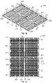
- FIG. 4 illustrates an example screening assembly that was generated from screening members and subgrid structures as described below with reference to FIGS. 1 to 3A , according to an embodiment.
- FIG. 5 illustrates results of actual field testing of screening assemblies, according to an embodiment.
- FIG. 6A illustrates a top view of a screen element that includes screening openings having rounded corners, according to an embodiment.
- FIG. 6B illustrates a side view of the screen element of FIG. 6A , according to an embodiment.
- FIG. 6C illustrates a top exploded view of a surface region of the screen element of FIG. 6A showing screening openings having rounded corners, according to an embodiment.
- FIG. 7A illustrates a top view of a screen element that includes transversely aligned screening openings, according to an embodiment.
- FIG. 7B illustrates an exploded top view of a portion of the screen element of FIG. 7A showing details of transversely aligned screening openings, according to an embodiment.
- FIG. 7C illustrates a top view of a screen element that includes longitudinally aligned screening openings, according to an embodiment.
- FIG. 7D illustrates an exploded top view of a portion of the screen element of FIG. 7C showing details of longitudinally aligned screening openings, according to an embodiment.
- FIG. 8A illustrates cross sectional view of a surface element having a thickness of approximately 0.007 inch, according to an embodiment.
- FIG. 8B illustrates cross sectional view of a first surface element having a thickness of approximately 0.005 inch, according to an embodiment.
- FIG. 8C illustrates cross sectional view of a second surface element having a thickness of approximately 0.005 inch, according to an embodiment.
- FIG. 9 illustrates a top view of a screen element and frame assembly with various regions that may be laser welded to an underlying subgrid, according to an embodiment.
- FIG. 10 illustrates a vibrational amplitude profile of a screen element that is partially bonded to a subgrid, according to an embodiment.
- TPU thermoplastic polyurethanes
- Disclosed embodiment TPU compositions may be used in injection molding processes to generate screening members for use in vibratory screening machines. Vibratory screening machines provide a capability to excite an installed screen such that materials placed upon the screen may be separated to a desired level. Oversized materials are separated from undersized materials.
- the disclosed compositions and screening members may be used in technology areas related to the oil industry, gas/oil separation, mining, water purification, and other related industrial applications.
- Disclosed embodiments provide screening members that satisfy demanding requirements, such as: fine openings of approximately 43 ⁇ m to approximately 100 ⁇ m that effectively screen similar-sized particles; large area screens on the order of several square feet having large open screening area on the order of 30% to 35%; screens that are thermally and mechanically stable that can withstand severe conditions during operation, such as compression loading (e.g. forces from 1,500 lbs. to 3,000 lbs. applied to edges of screening members and vibrational accelerations of up to 10 G) and loading of high temperature materials (e.g. between 37° C. and 94° C.), with significant weight loads and severe chemical and abrasive conditions of the materials being screened.
- demanding requirements such as: fine openings of approximately 43 ⁇ m to approximately 100 ⁇ m that effectively screen similar-sized particles; large area screens on the order of several square feet having large open screening area on the order of 30% to 35%; screens that are thermally and mechanically stable that can withstand severe conditions during operation, such as compression loading (e.g. forces from 1,500 lbs. to
- Disclosed embodiment materials and methods provide a hybrid approach in which small screen elements are micro-molded using disclosed TPU materials to reliably generate fine features on the order of 43 ⁇ m to approximately 100 ⁇ m to yield screen elements having large open screening area.
- the disclosed TPU materials include embodiments that feature optimized amounts of filler, heat stabilizer, and flow agent as additives to the appropriate thermoplastic polyurethane. These additives in turn allow for the small screen elements to be attached securely, such as via laser welding, to the subgrid structures to provide mechanical stability that may withstand the large mechanical loading and accelerations mentioned above.
- glass fibers may be used as filler material, which allow for strengthening of the TPU material and in turn allow the screen elements to be securely attached to the subgrid structures with increased structural stability.
- the amount of additives in the disclosed TPU compositions may also be varied based on the desired thickness T of the screen element surface elements, as discussed in detail in U.S. patent application Ser. No. 15/965,195 and U.S. patent application Ser. No. 62/648,771, which are hereby incorporated by reference herein.
- the thickness T of the screen element surface elements may be varied in an effort to maximize the percentage of open area on the overall screen assembly, which allows for increased effectiveness of the screening assembly when in use.
- a plurality of these optimized subgrid structures may then be assembled into screening structures having large surface areas, on the order of several square feet.
- the screen assemblies based on the disclosed TPU compositions may be utilized, for example, in the manner described in U.S. patent application Ser. No. 15/965,195 and U.s. patent application Ser. No. 62/648,771.
- the grid framework based upon the disclosed TPU compositions may provide the required durability against damage or deformation under the substantial vibratory load burdens it is subjected to when secured to a vibratory screening machine.
- the subgrids when assembled to form the complete screen assembly, are strong enough not only to withstand the forces required to secure the screen assembly to the vibratory screening machine, but also to withstand the extreme conditions that may be present in the vibratory loading.
- a method of securing the screen elements to the subgrid may include laser welding of the fusion bars arranged on the subgrids.
- the disclosed TPU compositions may therefore be utilized to create the referenced vibratory screening apparatus, capable of withstanding the extreme conditions discussed herein and in U.S. patent application Ser. No. 15/965,195.
- Screen assemblies based on disclosed TPU compositions may also be configured to be mounted on vibratory screening machines described in U.S. Pat. Nos. 7,578,394; 5,332,101; 6,669,027; 6,431,366; and 6,820,748.
- Such screen assemblies may include: side portions or binder bars including U-shaped members configured to receive over mount type tensioning members, as described in U.S. Pat. No. 5,332,101; side portions or binder bars including finger receiving apertures configured to receive under mount type tensioning, as described in U.S. Pat. No. 6,669,027; side members or binder bars for compression loading, as described in U.S. Pat. No. 7,578,394; or may be configured for attachment and loading on multi-tiered machines, such as the machines described in U.S. Pat. No. 6,431,366.
- Screen assemblies and/or screen elements based on disclosed TPU compositions may also be configured to include features described in U.S. Pat. No. 8,443,984, including the guide assembly technologies described therein and preformed panel technologies described therein. Still further, screen assemblies and screen elements based on disclosed TPU compositions may be configured to be incorporated into pre-screening technologies, compatible with mounting structures and screen configurations, described in U.S. Pat. Nos. 7,578,394; 5,332,101; 4,882,054; 4,857,176; 6,669,027; 7,228,971; 6,431,366; 6,820,748; 8,443,984; and 8,439,203.
- the disclosure of each of these patent documents, along with their related patent families and applications, and the patents and patent applications referenced in these documents, are expressly incorporated herein by reference in their entireties.
- FIGS. 1 to 3A illustrate example embodiment screening members generated by injection molding processes using disclosed TPU compositions.
- FIGS. 1 to 1C show an embodiment screen element 416 having substantially parallel screen element end portions 20 , and substantially parallel screen element side portions 22 , that are substantially perpendicular to the screen element end portions 20 .
- Screen element 416 may include a plurality of tapered counter bores 470 , which may facilitate extraction of screen element 416 from a mold, as described in greater detail in the above-referenced patent documents.
- Screen element 416 may further include location apertures 424 , which may be located at a center of screen element 416 and at each of the four corners of screen element 416 . Location apertures 424 are useful for attaching screen element 416 to subgrid structures, as described in greater detail below with reference to FIGS. 3 and 3A .
- screen element 416 has a screening surface 13 that includes solid surface elements 84 running parallel to the screen element end portions 20 and forming screening openings 86 , as also shown in the close-up view of FIG. 2 , as described in greater detail below.
- FIGS. 1B and 1C show a bottom view of screen element 416 having a first screen element support member 28 extending between the end portions 20 and being substantially perpendicular to the end portions 20 .
- FIG. 1B also shows a second screen element support member 30 perpendicular to the first screen element support member 28 extending between the side edge portions 22 , being approximately parallel to the end portions 20 and being substantially perpendicular to the side portions 22 .
- the screen element may further include a first series of reinforcement members 32 substantially parallel to the side edge portions 22 , and a second series of reinforcement members 34 substantially parallel to the end portions 20 .
- the end portions 20 , the side edge portions 22 , the first screen element support member 28 , the second screen element support member 30 , the first series reinforcement members 32 , and the second series of reinforcement members 34 structurally stabilize the screen surface elements 84 and screening openings 86 during various loadings, including distribution of a compression force and/or vibratory loading conditions.
- screen element 416 may include one or more adhesion arrangements 472 , which may include a plurality of extensions, cavities, or a combination of extensions and cavities.
- adhesion arrangement 472 is a plurality of cavity pockets.
- Adhesion arrangement 472 is configured to mate with complementary adhesion arrangements of a subgrid structure.
- subgrid structure 414 shown in FIGS. 3 and 3A ) has a plurality of fusion bars, 476 and 478 , that mate with cavity pockets 472 of screen element 416 , as described in greater detail below with reference to FIGS. 3 and 3A .
- the screening openings 86 may be elongated slots having a length L along a first direction, and width W along a second direction, separated by surface elements 84 have a thickness T along the second direction.
- Thickness T may be varied depending on the screening application and configuration of the screening openings 86 .
- Thickness T may be chosen to be approximately 0.003 inch to about 0.020 inch (i.e., about 76 ⁇ m to about 508 ⁇ m), depending on the open screening area desired, and the width W of screening openings 86 .
- the thickness T of the surface elements may be 0.015 inch (i.e., 381 ⁇ m).
- properties of disclosed TPU compositions allow formation of thinner surface elements, such as surface elements having a thickness T of 0.007 inch (i.e., 177.8 ⁇ m).
- T thickness of 0.007 inch
- a thickness T of 0.014 inch will provide a screen element that is about 10-15% open
- a thickness T of 0.003 inch will provide a screen element that is about 30-35% open, thus increasing open screening area.
- screening openings 86 have a width W.
- the width W may be approximately 38 ⁇ m to approximately 150 ⁇ m (i.e., about 0.0015 to about 0.0059 inch) between inner surfaces of each screen surface element 84 .
- the length-to-width ratios of the openings may be from 1:1 (i.e. corresponding to round pores) to 120:1 (i.e., long narrow slots).
- openings may preferably be rectangular and may have a length-to-width ratio of between about 20:1 (e.g. length 860 ⁇ m; width 43 ⁇ m) to about 30:1 (i.e., length about 1290 ⁇ m, and width about 43 ⁇ m).
- the screening openings are not required to be rectangular but may be thermoplastic injection molded to include any shape suitable to a particular screening application, including approximately square, circular, and/or oval.
- the screen surface elements 84 may include integral fiber materials (e.g., glass fibers) which may run substantially parallel to end portions 20 .
- Screen element 416 may be a single thermoplastic injection molded piece.
- Screen element 416 may also include multiple thermoplastic injection molded pieces, each configured to span one or more grid openings. Utilizing small thermoplastic injection molded screen elements 416 , which are attached to a grid framework as described below, provides substantial advantages over prior screen assemblies, as described in greater detail in the above-referenced patent documents.
- FIGS. 3 and 3A illustrate a process for attaching screen elements 416 to an end subgrid unit 414 , according to an embodiment.
- Screen elements 416 may be aligned with end subgrid unit 414 via elongated attachment members 444 (of subgrid 414 ) that engage with location apertures 424 on an underside of the screen element 416 (e.g., see FIGS. 1 to 1C ).
- elongated attachment members 444 of subgrid 414 pass into screen element location apertures 424 of screen element 416 .
- Elongated attachment members 444 of end subgrid 414 may then be melted to fill tapered bores of screen element attachment apertures 424 , to thereby secure screen element 416 to the subgrid unit 414 .
- Attachment via elongated attachment members 444 and screen element location apertures 424 is only one method for attaching screen member 416 to subgrid 414 .
- screen element 416 may be secured to end subgrid unit 414 using adhesives, fasteners and fastener apertures, laser welding, etc.
- fusion bars 476 and 478 , of subgrid 414 may be configured to fit into cavity pockets 472 of screen element 416 (e.g., see FIGS. 1 to 3C ).
- heat e.g., via laser welding, etc.
- fusion bars, 476 and 478 may be melted to form a bond between screen element 416 and subgrid 414 upon cooling.
- Arranging the screen elements 416 on subgrids allows for easy construction of complete screen assemblies with very fine screening openings. Arranging screen elements 416 on subgrids also allows for substantial variations in overall size and/or configuration of the screen assembly 10 , which may be varied by including greater or fewer subgrids or subgrids having different shapes, etc. Moreover, a screen assembly may be constructed having a variety of screening opening sizes or a gradient of screening opening sizes simply by incorporating screen elements 416 with the different size screening openings onto subgrids and joining the subgrids to form a desired configuration.
- subgrids e.g., subgrid 414
- Arranging screen elements 416 on subgrids also allows for substantial variations in overall size and/or configuration of the screen assembly 10 , which may be varied by including greater or fewer subgrids or subgrids having different shapes, etc.
- a screen assembly may be constructed having a variety of screening opening sizes or a gradient of screening opening sizes simply by incorporating screen elements 416 with the different size screening
- the screens described above with reference to FIGS. 1 to 3 , and disclosed in the above-reference patent documents, have small screening openings suitable for use as screening members.
- the disclosed TPU compositions additionally allow these screens to perform effectively in each of the following key areas: structural stability and durability; ability to withstand compression type loading; ability to withstand high temperatures; extended commercial life despite potential abrasion, cuts, or tearing; and fabrication methods that are not overly complicated, time consuming, or error-prone.
- TPU compositions having improved chemical properties that may be formed by injection molding into screening members and screening assemblies having improved physical properties.
- compositions generally include a TPU material, a heat stabilizer selected to optimize heat resistance of the composition, a flow agent selected to optimize use of the composition in injection molding, and a filler material selected to optimize rigidity of the resulting composite material.
- the filler may be included in an amount of less than about 10% by weight of the TPU. In one embodiment, the filler is provided in an amount of about 7% by weight of the TPU. In other exemplary embodiments, the filler is provided in amounts of less than about 7%, less than about 5%, or less than about 3%, of the weight of the TPU.
- One example of a filler material includes glass fibers. Glass fibers may be introduced in an amount that allows use of the composition in injection molding, improves rigidity of the composition upon hardening, increases temperature resistance of the final product, and yet does not preclude laser welding of the composition to other materials.
- An initial length of glass fibers may be between about 1.0 mm to about 4.0 mm.
- glass fibers may have an initial length of about 3.175 mm (i.e., 1 ⁇ 8 inch).
- Glass fibers may also have a diameter of less than about 20 ⁇ m, such as between about 2 ⁇ m and about 20 ⁇ m.
- the glass fibers have a diameter of between about 9 ⁇ m to about 13 ⁇ m.
- the glass fibers have a diameter of between about 10 ⁇ m to about 14 ⁇ m.
- glass fibers may have an initial length of 1 ⁇ 8 inch or less.
- glass fibers may have an initial length of 1 ⁇ 8 inch, 1/16 inch, 1/32 inch, 1/64 inch, etc. In other embodiments, glass fibers may have an initial length that is in a range from approximate 200 ⁇ m to approximately 800 ⁇ m. After processing, glass fibers may have a length that is considerably smaller than the starting length. For example, glass fibers may have a final length of less than 1 ⁇ m. In further embodiments, glass fibers may have an initial length of approximately 4 mm and may have a final length after processing of approximately 0.5 mm.
- the TPU material may be made from a low free isocyanate monomer prepolymer.
- the low free isocyanate monomer prepolymer may be chosen to be p-phenylene di-isocyanate.
- other prepolymers may be chosen.
- the TPU may first be generated by reacting a urethane prepolymer with a curing agent.
- the urethane prepolymer may be chosen to have a free polyisocyanate monomer content of less than 1% by weight.
- the TPU material may be a methylene diphenyl di-isocyanate (MDI) or a toluene di-isocyanate (TDI) modified polyester polyurethane.
- a modified polyester is a material in which side chains have been modified to increase hydrolysis resistance.
- the resulting material may then be thermally processed by extrusion at temperatures of 150° C., or higher, to form the TPU polymer.
- the urethane prepolymer may be prepared from a polyisocyanate monomer and a polyol including an alkane diol, polyether polyol, polyester polyol, polycaprolactone polyol, and/or polycarbonate polyol.
- the curing agent may include a diol, a triol, a tetrol, an alkylene polyol, a polyether polyol, a polyester polyol, a polycaprolactone polyol, a polycarbonate polyol, a diamine, or a diamine derivative.
- the heat stabilizer may be included in an amount of about 0.1% to about 5% by weight of the TPU.
- the heat stabilizer may be a sterically hindered phenolic antioxidant.
- the sterically hindered phenolic antioxidant may be pentaerythritol tetrakis (3-(3,5-di-tert-butyl-4-hydroxyphenyl)propionate) (CAS Registry No. 6683-19-8).
- an ultraviolet (UV) light stabilizer may be included.
- the heat stabilizer will also serve as a UV light stabilizer.
- the flow agent may be included in an amount of about 0.1% to about 5% by weight of the TPU.
- the flow agent may be chosen to be an ethylene steramide wax.
- the ethylene steramide wax may include octadecanamide, N,N′-1,2-ethanediylbis (CAS Registry No. 110-30-5) and stearic acid (CAS Registry No. 57-11-4). In other embodiments, other flow agents may be chosen.
- glass fibers may have a diameter or width between about 2 to about 20 ⁇ m, between about 9 to about 13 ⁇ m, or may have a diameter or width about 11 ⁇ m.
- the glass fibers may have an initial length of between about 3.1 mm to about 3.2 mm.
- a final average length of the glass fibers, in a hardened state after injection molding, may be less than about 1.5 mm due to breakage of fibers during processing.
- the fibers In a final hardened state after injection molding, the fibers may be characterized by a distribution of lengths ranging from about 1.0 mm to about 3.2 mm, with some fibers remaining unbroken.
- glass fibers may have initial and final lengths that are smaller.
- glass fibers after processing may have an initial length that is 1 ⁇ 8 inch, 1/16 inch, 1/32 inch, 1/64 inch, etc. In other embodiments, glass fibers may have an initial length that is in a range from approximate 200 ⁇ m to approximately 800 ⁇ m. After processing, glass fibers may have a length that is considerably smaller than the initial length. For example, glass fibers may have a final length of less than 1 mm, less than 1 ⁇ m, etc.
- Embodiment methods include reacting a TPU, a heat stabilizer, a flow agent, and a filler material, at a temperature greater than about 150° C., to generate a TPU composition.
- a material may be generated by incorporating fewer components.
- a composition may be generated that omits that heat stabilizer, omits the flow agent, omits the filler material, or that omits two or more of these components.
- the filler may include a glass fiber having a diameter of between about 2 ⁇ m to about 20 ⁇ m, in an amount selected to optimize rigidity of articles of manufacture molded from the TPU composition.
- the TPU may be polycarbonate TPU or may be a polyester or modified polyester TPU.
- the TPU may be a pre-polymer prior to the reacting step.
- the glass fiber may be present in an amount between about 1% to about 10% by weight of the TPU. In one embodiment, the glass fiber may be present in an amount of about 7% by weight of the TPU.
- Articles of manufacture molded from compositions disclosed herein are suitable to be joined by various methods including laser welding.
- the resulting articles may be laser welded to other articles, such as support structures.
- Example articles of manufacture include screening members for vibratory shaker screens, as described above.
- Disclosed TPU material described above, may then be used in an injection molding process to generate a screening member.
- the TPU material may be introduced/injected into a suitably designed mold at an elevated temperature.
- the temperature may be chosen to be a temperature at which the TPU material has a sufficiently reduced viscosity to allow the material to flow into the mold.
- the resulting solidified screening member may be removed from the mold.
- the resulting screening member may be designed to have a plurality of openings having opening widths ranging from about 38 ⁇ m to about 150 ⁇ m. Screens with such openings may be used for removing particles from various industrial fluids to thereby filter/clean the fluids. Particles that are larger than widths of screening openings may be effectively removed.
- the desirable thermal properties of the TPU material allows screening members made from the TPU material to effectively screen particles at elevated temperatures (e.g., service temperatures of up to about 82 to 94° C.).
- Characteristics of disclosed TPU compositions, and products generated therefrom include temperature and flow characteristics that facilitate production of very fine, high-resolution structures using techniques such as injection molding. Resulting end products also have excellent thermal stability at elevated operating temperatures (e.g. up to about 94° C.). Resulting structures also exhibit sufficient structural rigidity to withstand compression loading while maintaining small openings that allow for screening of micron-scale particulate matter. Structures generated from disclosed TPU materials also exhibit cut, tear, and abrasion resistance, as well as chemical resistance in hydrocarbon-rich environments (e.g. environments including hydrocarbons such as diesel fuel).
- thermoplastic compositions including polyurethanes, which are a class of macromolecular plastics known as polymers.
- polymers such as polyurethanes, include smaller, repeating units known as monomers.
- Monomers may be chemically linked end-to-end to form a primary long-chain backbone molecule with or without attached side groups.
- polyurethane polymers may be characterized by a molecular backbone including carbonate groups (—NHCO 2 ), for example.
- thermoplastic compositions While generally categorized as plastics, thermoplastic compositions include polymer chains that are not covalently bonded, or crossed linked, to one another. This lack of polymer chain crosslinking allows thermoplastic polymers to be melted when subjected to elevated temperatures. Moreover, thermoplastics are reversibly thermoformable, meaning that they may be melted, formed into a desired structure, and re-melted in whole or in part at a later time. The ability to re-melt thermoplastics allows optional downstream processing (e.g., recycling) of articles generated from thermoplastics. Such TPU based articles may also be melted at discrete locations by applying a heat source to a specific location on an article. In this regard, articles generated from disclosed TPU composition are amenable to joining using welding (e.g., laser welding) to effectively secure TPU-based screening members to suitable screening frames.
- welding e.g., laser welding
- TPU materials exhibit desirable properties under extreme conditions of temperature and harsh chemical environments.
- TPU materials may be made from a prepolymer.
- An example prepolymer may include a p-phenylene di-isocyanate (PPDI) with low free isocyanate content.
- PPDI p-phenylene di-isocyanate
- different suitable prepolymers may be used.
- thermoplastic polyurethanes suitable for use in fabricating the disclosed screen elements.
- the disclosed polyurethanes comprise hard and soft segments which can be artfully manipulated by the fabricator to produce final polyurethanes having the desired properties, for example, abrasion control, flowable during injection molding, anti-fracture properties and the like.
- the disclosed polyurethanes, as described herein have from a 85 Shore A to 59 Shore D.
- thermoplastic polyurethanes can be fabricated from a prepolymer and a curing agent.
- the prepolymer, as well as, the curing agent can be purchased from chemical suppliers or the prepolymer and curing agent can be synthesized by the fabricator.
- the disclosed prepolymer can comprise any urethane forming unit.
- the urethane forming units comprise two types: aryl diisocyanates and aliphatic diisocyanates.
- the urethane forming unit is reacted with a polyol that serves to connect two diisocyanate moieties.
- the prepolymer can be formed by the following reaction:
- R is a carbon skeleton of 2 to 15 carbon atoms, and/or a bivalent aromatic radical of 6 to 18 carbon atoms.
- R is an alkylene unit having 2 to 15 carbon atoms, i.e., from 2 to 15 methylene units, —(CH 2 ) 2 — to —(CH 2 ) 15 —.
- R can comprise from 2 to 15 methylene units, for example, 2, 3, 4, 5, 6, 7, 8, 9, 10, 11, 12, 13, 14, or 15 methylene units.
- ONC—R—NCO include 1,6-hexamethylene diisocyanate, 1-isocyanato-3-isocyanatomethyl-3,5,5-trimethyl-cyclohexane (isophorone diisocyanate, IPDI) and 4,4′-diisocyanato dicyclohexylmethane.
- R is a bivalent aromatic radical of 6 to 18 carbon atoms.
- R is formed from a methylene diphenyl diisocyanate (MDI) wherein R has the formula:
- R can be a 1,2-phenylene. 1,3-phenylene, of a 1,4-phenylene unit having the formula:
- the disclosed R 1 units can be alkylene unit having 2 to 10 carbon atoms, i.e., from 2 to 10 methylene units, —(CH 2 ) 2 — to —(CH 2 ) 10 —.
- R 1 can comprise from 2 to 10 methylene units, for example, 2, 3, 4, 5, 6, 7, 8, 9, or 10 methylene units.
- Non-limiting examples of HO—R—OH include 1,2-ethanediol, 1,3-propanediol, 1,4-butanediol, 1,5-pemtanediol, 1,6-hexanediol, 1,7-heptanediol, 1-8-octanediol, 1,9-nonanediol, and 1,10-decanediol.
- R 1 units can be derived from a caprolactone diol unit having the formula:
- a non-limiting example of a polycaprolactone diol prepolymer has the formula:
- the index x is from 2 to about 6
- the index n is from 2 to about 8.
- a further non-limiting example of a prepolymer derived from a polycaprolactone diol unit has the formula:
- index x is from 2 to about 6
- index n is from 2 to about 8.
- the disclosed R 1 units can be derived from a polyglycidyl diol having the formula:
- a non-limiting example of a polyglycidyl diol prepolymer has the formula:
- the index x is from 2 to about 6
- the index n is from 2 to about 8.
- a further non-limiting example of a prepolymer derived from a polyglycidyl diol unit has the formula:
- index x is from 2 to about 6
- index n is from 2 to about 8.
- the disclosed R 1 units can be derived from a polylactide diol having the formula:
- a non-limiting example of a polylactide diol prepolymer has the formula:
- the index x is from 2 to about 6
- the index n is from 2 to about 8.
- a further non-limiting example of a prepolymer derived from a polylactide diol unit has the formula:
- index x is from 2 to about 6
- index n is from 2 to about 8.
- the disclosed R 1 units can be derived from diols having the formula:
- a non-limiting example of a polycarbonate diol prepolymer has the formula:
- index x is from 2 to about 6
- index n is from 2 to about 8.
- the disclosed R 1 units can be derived from polyalkylene diols having the formula: HO—(CH 2 ) z —OH wherein the index z is from about 4 to about 25.
- a non-limiting example of a polyalkylene diol prepolymer has the formula:
- the disclosed R 1 units can be derived from a polyether diol.
- the R 1 comprises a polyethylene glycol having the formula: HO—[(CH 2 CH 2 O) y ]CH 2 CH 2 —OH wherein the index y is from about 4 to about 25.
- the following is a non-limiting embodiment of the disclosed PEG prepolymers:
- the disclosed R 1 units can be derived from a polyethylene glycol having the formula:
- thermoplastic polyurethanes having the formula:
- the curing agents are chosen from polycaprolactone diols, polyglycidyl diols, polylactide diols, polycarabonate diols, polyethylene glycols, polypropylene glycols, or polyalkylene diols.
- the disclosed R 2 units are chosen from:
- Polyester polyurethane forming unit ii) Polyester polyurethane forming unit:
- Polyester polyurethane forming unit iii) Polyester polyurethane forming unit:
- the curing agent can be a repeating or non-repeating polyol.
- a branched polyol having the formula:
- a non-stoichiometric amount of a first curing agent can be combined with a polyol in an amount that provides the necessary hydroxyl units to consume the available isocyanate groups.
- the disclosed polyurethanes have from a 85 Shore A to 59 Shore D durometer value.
- the desired hardness of the resulting thermoplastic polyurethanes can be achieved either by the artful selection of the disclosed R, R 1 and R 2 units together with the proper selection of the indices x, y, m and n.
- Another disclosed method is to select two polymers having different Shore D durometer values and to admix the two polymers to obtain an intermediary Shore D durometer hardness value between the values of the two polymers.
- a 95 Shore A could convert to a 45 Shore D which can be combined with a 56 Shore D to form a polymer having an intermediate hardness.
- a screen element comprising:
- thermoplastic polyurethane having a first hardness
- thermoplastic polyurethane having a second hardness
- thermoplastic polyurethane having a hardness of from approximately 85 Shore A to 59 Shore D;
- the screen element is a single injection molded piece having a plurality of openings from 43 ⁇ m to 100 ⁇ m;
- the amount of openings is from 10% to 35% of the screen element.
- the first polyurethane and the second polyurethane are formed by reacting a prepolymer having the formula chosen from:
- the index x is from 2 to about 6, the index y is from about 4 to about 25, index z is from about 4 to about 25, and the index n is from 2 to about 8; and wherein further the prepolymer contains less than 0.1% by weight of excess isocyanate moieties; with a curing agent, wherein the curing agent is chosen from polycaprolactone diols, polyglycidyl diols, polylactide diols, polycarabonate diols, polyethylene glycols, polypropylene glycols, or polyalkylene diols.
- Example TPU materials may be generated as follows.
- a TPU polymer may be produced by reacting a urethane prepolymer, having a free polyisocyanate monomer content of less than 1% by weight, with a curing agent. The resulting material may then be thermally processed by extrusion at temperatures of 150° C. (or higher) to form the TPU material.
- the urethane prepolymer may be prepared from a polyisocyanate monomer and a polyol including an alkane diol, a polyether polyol, a polyester polyol, a polycaprolactone polyol, and/or a polycarbonate polyol.
- the curing agent may include a diol, a triol, a tetrol, an alkylene polyol, a polyether polyol, a polyester polyol, a polycaprolactone polyol, a polycarbonate polyol, a diamine, or a diamine derivative.
- Disclosed TPU materials may then be combined with a heat stabilizer, a flow agent, and a filler material, according to various embodiments. In further embodiments, other additives may be included as needed.
- TPU compositions that may be formed by reacting a polyol with a polyisocyanate and polymer chain-extender.
- Example embodiments include synthetic production methods and processes for making TPU compositions.
- Disclosed methods may include reacting monomers, curing agents, and chain extenders in a reaction vessel to form pre-polymers.
- Disclosed methods may further include forming pre-polymers by reacting a di-isocyanate (OCN—R—NCO) with a diol (HO—R—OH). Formation of a pre-polymer includes chemically linking two reactant molecules to produce a chemical product having an alcohol (OH) at one position and an isocyanate (NCO) at another position of the product molecule.
- a disclosed pre-polymer includes both a reactive alcohol (OH) and a reactive isocyanate (NCO).
- Articles generated using the TPU compositions disclosed herein may be fully cured polymer resins that may be stored as a solid plastic.
- Non-limiting examples of curing agents may include ethane diol, propane diol, butane diol, cyclohexane dimethanol, hydroquinone-bis-hydroxyalkyl (e.g., hydroquinone-bis-hydroxyethyl ether), diethylene glycol, dipropylene glycol, dibutylene glycol, triethylene glycol, etc., dimethylthio-2,4-toluenediamine, di-p-aminobenzoate, phenyldiethanol amine mixture, methylene dianiline sodium chloride complex, etc.
- curing agents may include ethane diol, propane diol, butane diol, cyclohexane dimethanol, hydroquinone-bis-hydroxyalkyl (e.g., hydroquinone-bis-hydroxyethyl ether), diethylene glycol, dipropylene glycol, dibutylene glycol, triethylene glycol, etc., dimethylthio-2,4-
- a polyol may include an alkane diol, polyether polyol, polyester polyol, polycaprolactone polyol, and/or polycarbonate polyol.
- the polyol may include a polycarbonate polyol either, alone or in combination with other polyols.
- Disclosed heat/thermal stabilizers may include additives such as organosulfur compounds, which are efficient hydroperoxide decomposers that thermally stabilize polymers.
- Non-limiting example heat stabilizers include: organophosphites such as triphenyl phosphite, tris-(2,6-dimethylphenyl) phosphite, tris-(mixed mono- and di-nonylphenyl) phosphite etc.; phosphonates such as dimethylbenzene phosphonate, etc.; phosphates such as trimethyl phosphate, etc.; dihexylthiodiformate dicyclohexyl-10,10′-thiodidecylate dicerotylthiodiformate dicerotyl-10,10′-thiodidecylate dioctyl-4,4-thiodibutyrate diphenyl-2,2′-thiodiacetate (thiodiglycolate) dilauryl
- thermal stabilizers may be included in amounts of about 0.0001% to about 5% by weight, based on the weight of the base-polymer component used in the TPU composition. Inclusion of organosulfur compounds may also improve thermal stability of TPU compositions as well as articles produced therefrom.
- a heat stabilizer may be a sterically hindered phenolic antioxidant, such as Pentaerythritol Tetrakis (3-(3,5-di-tert-butyl-4-hydroxyphenyl)propionate) (CAS Registry No. 6683-19-8).
- the heat stabilizer may be included in amounts ranging from about 0.1% to about 5% by weight of the TPU.
- Flow agents are used to enhance flow characteristics of TPU materials so that such TPU materials may be easily injected into a mold.
- Injection times for disclosed TPU materials are preferably between about 1 to about 2 seconds. In an embodiment, flow times averaging about 1.6 seconds have been achieved. Flow agents are used to achieve such injection times.
- Disclosed TPU compositions may include flow agents that improve lubrication to increase the flow of melted polymer compositions relative to an external surface (i.e., to increase external flow). Flow agents may also increase the flow of individual polymer chains within a thermoplastic melt (i.e., to increase internal flow).
- TPU compositions may include an internal flow agent that may be readily compatible with the polymer matrix.
- the internal flow agent may have a similar polarity that improves the ease of flow of the melt by preventing internal friction between the individual particles of the polymer.
- TPU compositions including internal flow agents may improve molding characteristics.
- TPU compositions may be used to produce articles having small or very small openings.
- TPU compositions may be used to produce articles having very fine openings by injection molding.
- the improved flow of the TPU compositions allows production of high-resolution articles having small or very small openings.
- TPU compositions may include an external flow agent that may be more or less compatible with the polymer matrix of a TPU composition.
- an external flow agent may have a different polarity relative to the TPU composition polymer. Since external flow agents may not be compatible with the TPU polymer matrix of the composition, external flow agents may act as an external lubricating film between the polymer and hot metallic surfaces of processing machines. Thus, external lubricants may prevent a polymer melt from adhering to machine parts (e.g., such as an extruder), and may also reduce the force required to remove a cured polymer from a mold (i.e., may improve demolding) in the case of injection molding.
- machine parts e.g., such as an extruder
- Non-limiting, examples of flow agents that may be included in TPU compositions include amines (e.g., ethylene bisstearamide), waxes, lubricants, talc, and dispersants.
- Disclosed embodiments provide TPU compositions that may also include one or more inorganic flow agents such as hydrated silicas, amorphous alumina, glassy silicas, glassy phosphates, glassy borates, glassy oxides, titania, talc, mica, fumed silicas, kaolin, attapulgite, calcium silicates, alumina, and magnesium silicates.
- the amount of flow agent may vary with the nature and particle size of the particular flow agent selected.
- the flow agent may be a wax, such as an ethylene steramide wax.
- An ethylene steramide wax may include octadecanamide, N,N′-1,2-ethanediylbis (C 38 H 76 N 2 O 2 ; CAS Registry No. 100-30-5) and stearic acid [CH 3 (CH 2 ) 16 COOH; CAS Registry No. 57-11-4].
- the flow agent may be present in amounts from about 0.1% to about 5% by weight of the TPU.
- Improved flow characteristics of TPU compositions may be achieved by reducing or eliminating the presence of certain compounds, such as calcium stearate, for example.
- TPU compositions may also include fillers that may include inorganic materials. Fillers strengthen and stiffen the TPU based material, enhancing properties of objects injection molded from the TPU material. For example, fillers help to maintain shapes of small openings, holes, or pores, formed in objects injection molded from the TPU composition. In some embodiments, for example, the fibers allow transmission of light for use in laser welding of molded TPU components to support structures.
- glass fibers may be used as filler material, as described above.
- Glass fibers may take the form of solid or hollow glass tubes.
- glass tubes may have a diameter (or width, if not round) of between about 2 ⁇ m to about 20 ⁇ m.
- glass fibers may have a diameter (or width, if not round) of between about 9 ⁇ m to about 13 ⁇ m.
- glass fibers may have a 11 ⁇ m diameter or width.
- Glass fibers may have an initial length of between about 3.0 mm to about 3.4 mm. In an exemplary embodiment, glass fibers may have an initial length of 1 ⁇ 8 inch (i.e., 3.175 mm).
- glass fibers may have an initial length that is 1/16 inch, 1/32 inch, 1/64 inch, etc. During processing of the TPU material, however, glass fibers may break and thereby become shorter. In a hardened state after injection molding, glass fibers may have an average length of less than about 1.5 mm, with a range of most fibers being between about 1.0 mm to about 3.2 mm. After processing, glass fibers may have a length that is considerably smaller than the starting length. For example, glass fibers may have a final length of less than 1 ⁇ m. Some of the fibers retain their original length, but most are broken into smaller pieces.
- TPU composition To allow laser welding of the TPU composition, it is desirable to use as little glass fiber as possible. Too much glass fiber leads to an unacceptably high amount of reflection/refraction of laser light. Additionally, desired properties of the TPU composition may degrade with increasing glass fiber content. Glass fibers having a sufficiently large diameter may work better for laser weldable compositions. Such large diameter fibers may also provide desirable strengthening and stiffening properties. The diameter of glass fibers should not be too large, however, as desirable flow properties may degrade with increasing diameter of glass fibers, reducing the suitability of the resulting composition for injection molding.
- Glass fiber filler materials should not contain fibers having a diameter of greater than 50 ⁇ m, and should preferably have a diameter of less than 20 ⁇ m, in compositions developed for injection molding of structures having features on a sub-millimeter scale. Carbon fibers should be avoided in that they may not work for laser welding because they are not translucent.
- TPU based objects that are designed to be joinable via laser welding may have optical properties that allow laser light to pass through the TPU material. As such, laser light may pass through the TPU object and may hit an adjacent structure such as to a nylon subgrid.
- the nylon material of the subgrid is a thermoplastic having a dark color that absorbs laser light and may thereby be heated by the laser.
- the TPU and the adjacent nylon may be heated to a temperature above their respective melting temperatures. In this way, both materials may be melted, and upon cooling, a mechanical bond may be formed at an interface between the TPU and the nylon, thereby welding the components together.
- TPU compositions may also include particulate fillers, which may be of any configuration including, for example, spheres, plates, fibers, acicular (i.e., needle like) structures, flakes, whiskers, or irregular shapes.
- Suitable fillers may have an average longest dimension in a range from about 1 nm to about 500 ⁇ m.
- Some embodiments may include filler materials with average longest dimension in a range from about 10 nm to about 100 ⁇ m.
- Some fibrous, acicular, or whisker-shaped filler materials e.g., glass or wollastonite
- Plate-like filler materials may have a mean aspect ratio (i.e., mean diameter of a circle of the same area/mean thickness) that is greater than about 5.
- plate-like filter materials may have an aspect ratio in a range from about 10 to about 1000. In a further embodiment, such plate-like materials may have an aspect ratio in a range from about 10 to about 200. Bimodal, trimodal, or higher mixtures of aspect ratios may also be used. Combinations of fillers may also be used in certain embodiments.
- a TPU composition may include natural, synthetic, mineral, or non-mineral filler materials.
- suitable filler materials may be chosen to have sufficient thermal resistance so that a solid physical structure of the filler material may be maintained, at least at the processing temperature of the TPU composition with which it is combined.
- suitable fillers may include clays, nanoclays, carbon black, wood flour (with or without oil), and various forms of silica.
- Silica materials may be precipitated or hydrated, fumed or pyrogenic, vitreous, fused or colloidal.
- Such silica materials may include common sand, glass, metals, and inorganic oxides.
- Inorganic oxides may include oxides of metals in periods 2, 3, 4, 5 and 6 of groups IB, IIB, IIIA, IIIB, IVA, IVB (except carbon), VA, VIA, VIIA, and VIII, of the periodic table.
- Filler materials may also include oxides of metals, such as aluminum oxide, titanium oxide, zirconium oxide, titanium dioxide, nanoscale titanium oxide, aluminum trihydrate, vanadium oxide, magnesium oxide, antimony trioxide, hydroxides of aluminum, ammonium, or magnesium. Filler materials may further include carbonates of alkali and alkaline earth metals, such as calcium carbonate, barium carbonate, and magnesium carbonate. Mineral based materials may include calcium silicate, diatomaceous earth, fuller earth, kieselguhr, mica, talc, slate flour, volcanic ash, cotton flock, asbestos, and kaolin.
- Filler materials may further include alkali and alkaline earth metal sulfates, for example, sulfates of barium and calcium sulfate, titanium, zeolites, wollastonite, titanium boride, zinc borate, tungsten carbide, ferrites, molybdenum disulfide, cristobalite, aluminosilicates including vermiculite, bentonite, montmorillonite, Na-montmorillonite, Ca-montmorillonite, hydrated sodium calcium aluminum magnesium silicate hydroxide, pyrophyllite, magnesium aluminum silicates, lithium aluminum silicates, zirconium silicates, and combinations of the above-described filler materials.
- alkali and alkaline earth metal sulfates for example, sulfates of barium and calcium sulfate, titanium, zeolites, wollastonite, titanium boride, zinc borate, tungsten carbide, ferrites, molybdenum disulf
- TPU compositions may include fibrous fillers such as glass fibers (as described above), basalt fibers, aramid fibers, carbon fibers, carbon nanofibers, carbon nanotubes, carbon buckyballs, ultra-high molecular weight polyethylene fibers, melamine fibers, polyamide fibers, cellulose fiber, metal fibers, potassium titanate whiskers, and aluminum borate whiskers.
- fibrous fillers such as glass fibers (as described above), basalt fibers, aramid fibers, carbon fibers, carbon nanofibers, carbon nanotubes, carbon buckyballs, ultra-high molecular weight polyethylene fibers, melamine fibers, polyamide fibers, cellulose fiber, metal fibers, potassium titanate whiskers, and aluminum borate whiskers.
- TPU compositions may include glass fiber fillers, as described above.
- Glass fiber fillers may be of E-glass, S-glass, AR-glass, T-glass, D-glass and R-glass.
- the glass fiber diameter may be within a range from about 5 ⁇ m to about 35 ⁇ m. In other embodiments, the diameter of the glass fibers may be in a range from about 9 to about 20 ⁇ m. In further embodiments, glass fibers may have a length of about 3.2 mm or less.
- TPU compositions including glass fillers may confer improved thermal stability to the TPU compositions and articles produced them.
- Disclosed embodiments may include compositions containing a glass filler with concentrations in a range from about 0.1% to about 7% by weight. Embodiments may also include glass filler at concentrations ranging from about 1% to about 2%; about 2% to about 3%; 3% to about 4%; about 4% to about 5%; about 5% to about 6%; about 6% to about 7%; about 7% to about 8%; about 8% to about 9%; about 9% to about 10%; about 10% to about 11%; about 11% to about 12%; about 12% to about 13%; about 13% to about 14%; about 14% to about 15%; about 15% to about 16%; about 16% to about 17%; about 17% to about 18%; about 18% to about 19%; and about 19% to about 20%.
- a glass filler concentration may be about 1%. In certain embodiments a glass filler concentration may be about 3%. In certain embodiments a glass filler concentration may be about 5%. In certain embodiments a glass filler concentration may be about 7%. In certain embodiments a glass filler concentration may be about 10%.
- embodiments may include glass filler material wherein individual glass fibers may have a diameter or width in a range from about 1 ⁇ m to about 50 ⁇ m.
- the glass filler may be characterized by a narrow distribution of fiber diameters such that at least 90% of the glass fibers have a specific diameter or width.
- Other embodiments may include a glass filler having a broader distribution of diameters or widths spanning a range from about 1 ⁇ m to about 20 ⁇ m.
- Further embodiments may include glass filler having a glass fiber diameter or width distribution spanning a range: from about 1 ⁇ m to about 2 ⁇ m; from about 2 ⁇ m to about 3 ⁇ m; from about 3 ⁇ m to about 4 ⁇ m; from about 4 ⁇ m to about 5 ⁇ m; from about 5 ⁇ m to about 6 ⁇ m; from about 6 ⁇ m to about 7 ⁇ m; from about 7 ⁇ m to about 8 ⁇ m; from about 8 ⁇ m to about 9 ⁇ m; from about 9 ⁇ m to about 10 ⁇ m; from about 10 ⁇ m to about 11 ⁇ m; from about 11 ⁇ m to about 12 ⁇ m; from about 12 ⁇ m to about 13 ⁇ m; from about 13 ⁇ m to about 14 ⁇ m; from about 14 ⁇ m to about 15 ⁇ m; from about 15 ⁇ m to about 16 ⁇ m; from about 16 ⁇ m to about 17 ⁇ m; from about 17 ⁇ m to about 18 ⁇ m; from about 18 ⁇ m to about 19
- TPU compositions may include glass fiber fillers that include a surface treatment agent and optionally a coupling agent, according to an embodiment.
- a coupling agent many suitable materials may be used as a coupling agent. Examples include silane-based coupling agents, titanate-based coupling agents, or a mixture thereof.
- Applicable silane-based coupling agents for example, may include aminosilane, epoxysilane, amidesilane, azidesilane, and acrylsilane.
- TPU compositions may also include other suitable inorganic fibers such as: carbon fibers, carbon/glass hybrid fibers, boron fibers, graphite fibers, etc.
- suitable inorganic fibers such as: carbon fibers, carbon/glass hybrid fibers, boron fibers, graphite fibers, etc.
- Various ceramic fibers can also be utilized such as alumina-silica fibers, alumina fibers, silicon carbide fibers, etc.
- Metallic fibers such as aluminum fibers, nickel fibers, steel, stainless steel fibers, etc., may also be used.
- TPU compositions may be generated by a process in which TPU reactants may be combined with filler materials (e.g., fiber fillers) and other optional additives. The combination of materials may then be physically mixed in a mixing or blending apparatus.
- filler materials e.g., fiber fillers
- An example mixing or blending apparatus may include: a Banbury, a twin-screw extruder, a Buss Kneader, etc.
- filler and base TPU composition materials may be mixed or blended to generate a TPU composition blend having fibers incorporated therein.
- the resulting TPU composition having fillers (e.g., glass fibers), and optionally other additional additives, may be cooled to generate a solid mass.
- the resulting solid mass may then be pelletized or otherwise divided into suitable size particles (e.g., granulated) for use in an injection molding process.
- the injection molding process may be used to generate an article of manufacture such as a screen or screen element.
- Optional additives to TPU compositions may include dispersants.
- dispersants may help to generate a uniform dispersion of base TPU composition and additional components such as fillers.
- a dispersant may also improve mechanical and optical properties of a resulting TPU composition that includes fillers.
- waxes may be used as dispersants.
- wax dispersants suitable for use in disclosed TPU compositions, include: polyethylene waxes, amide waxes, and montan waxes.
- TPU compositions disclosed herein may include an amide wax dispersant, such as N,N-bis-stearyl ethylenediamine. The use of such a wax dispersant may increase thermal stability of the TPU composition yet may have little impact on polymer transparency.
- inclusion of dispersants in disclosed TPU compositions may have at least to desirable effects: (1) improved thermal stability of compositions and articles produced therefrom, and (2) desirable optical properties that are suitable for downstream processing including laser welding.
- Disclosed TPU compositions may further include antioxidants, according to an embodiment.
- Antioxidants may be used to terminate oxidation reactions, that may occur due to various weathering conditions, and/or may be used to reduce degradation of a TPU composition.
- articles formed of synthetic polymers may react with atmospheric oxygen when placed into service.
- articles formed of synthetic polymers may undergo auto-oxidization due to free-radical chain reactions.
- Oxygen sources e.g., atmospheric oxygen, alone or in combination with a free radical initiator
- Oxygen sources may react with substrates included in disclosed TPU compositions. Such reactions may compromise integrity of the TPU composition and articles produced therefrom.
- Inclusion of antioxidants therefore, may improve chemical stability of TPU compositions as well as improving chemical stability of articles generated therefrom.
- Embodiment TPU compositions may include Hydrogen-donating antioxidants (AH), such as hindered phenols and secondary aromatic amines.
- AH Hydrogen-donating antioxidants
- Such AH additives may inhibit oxidation of TPU compositions by competing with organic substrates for peroxy radicals. Such competition for peroxy radicals may terminate chain reactions and thereby stabilize or prevent further oxidation reactions.
- Inclusion of antioxidants in disclosed TPU compositions may inhibit formation of free radicals.
- AH being a light stabilizer
- AH may also provide thermal stability when included in disclosed TPU compositions.
- certain embodiments may include additives (e.g., AH) that enhance stability of polymers exposed to UV light and heat.
- additives e.g., AH
- Articles generated from disclosed TPU compositions having antioxidants may, therefore, be resistant to weathering and have improved function and/or lifespan, when deployed under high-temperature conditions, relative to articles generated from TPU compositions lacking antioxidants.
- Disclosed TPU compositions may further include UV absorbers, according to an embodiment.
- UV absorbers convert absorbed UV radiation to heat by reversible intramolecular proton transfer reactions.
- UV absorbers may absorb UV radiation that would otherwise be absorbed by the TPU composition.
- the resulting reduced absorption of UV rays by the TPU composition may help to reduce UV radiation induced weathering of the TPU composition.
- Non-limiting example UV-absorbers may include oxanilides for polyamides, benzophenones for polyvinyl chloride (PVC), and benzotriazoles and hydroxyphenyltriazines for polycarbonate materials.
- 2-(2′-Hydroxy-3′-sec-butyl-5′-tert-butylphenyl)benzotriazole may provide UV light stabilization for polycarbonate, polyester, polyacetal, polyamides, TPU materials, styrene-based homopolymers, and copolymers. These and other UV absorbers may improve the stability of disclosed TPU compositions and articles produced therefrom, according to various embodiments.
- TPU compositions may further include anti-ozonants which may prevent or slow degradation of TPU materials caused by ozone gas in the air (i.e., may reduce ozone cracking).
- antiozonates may include: p-Phenylenediamines, such as 6PPP (N-(1,3-dimethylbutyl)-N′-phenyl-p-phenylenediamine) or IPPD (N-isopropyl-N′-phenyl-p-phenylenediamine); 6-ethoxy-2,2,4-trimethyl-1,2-dihydroquinoline, (ETMQ) ethylene diurea (EDU), and paraffin waxes that may form a surface barrier.
- ETMQ 6-ethoxy-2,2,4-trimethyl-1,2-dihydroquinoline,
- ETMQ 6-ethoxy-2,2,4-trimethyl-1,2-dihydroquinoline
- ETMQ 6-ethoxy-2,2,4-trimethyl-1,2-dihydroquino
- an example mixture may be prepared as follows.
- the starting material may be chosen to be a polycarbonate-based thermoplastic polyurethane.
- a filler material may be chosen to be small diameter (as described above) glass fibers included in an amount from between about 3% and about 10% by weight.
- a flow agent may then be chosen to be included in an amount of between about 0.1% to about 5% by weight.
- the flow agent may be taken to be a mixture of octadecanamide, N,N′-1,2-ethanediylbis and stearic acid.
- a thermal-stabilizing agent may be chosen to be pentaerythritol tetrakis(3-(3,5-di-tert-butyl-4-hydroxyphenyl)propionate) included in an amount of between about 0.1% to about 5% by weight.
- the above-described thermoplastic mixture may then be injected into bulk thermoplastic rods then pelletized for downstream injection molding.
- Disclosed embodiments provide methods and processes for generating TPU compositions.
- Disclosed methods may include reacting (i.e., linking) pre-polymer units including an alcohol (OH) and an isocyanate (NCO) to effectively “grow” and/or extend a polymer chain or backbone.
- a TPU composition may be prepared by reacting a polyurethane pre-polymer and a curing agent, typically at temperatures from about 50° C. to about 150° C., for example, or from about 50° C. to about 100° C. Temperatures outside these ranges may also be employed in certain embodiments.
- Disclosed TPU compositions may be melted and formed into a desired shape, for example, by injection molding.
- Disclosed methods may further include a post curing step including heating the TPU material at temperatures from about 50° C. to about 200° C., or from about 100° C. to about 150° C., for a predetermined period of time. For example, TPU materials may be heated for about 1 hour to about 24 hours.
- various methods may include an extrusion step wherein a post-cured TPU composition may be extruded at temperatures from about 150° C. to about 270° C., or from about 190° C. or higher, to render the TPU composition in an intermediate form.
- the intermediate form may be suitable for downstream processing to generate a final form, such as a TPU based screen element.
- Disclosed methods may include a variety of additional processing operations.
- a disclosed method or process may include: reacting a polyurethane pre-polymer and a curing agent (i.e., polymerization); post curing the polyurethane; optionally grinding the material to generate a post cured polyurethane polymer in granulated form; extruding the post cured and/or optionally granulated polyurethane polymer; and optionally pelletizing the extruded TPU.
- a curing agent i.e., polymerization
- post curing the polyurethane optionally grinding the material to generate a post cured polyurethane polymer in granulated form
- extruding the post cured and/or optionally granulated polyurethane polymer optionally pelletizing the extruded TPU.
- the TPU composition may be generated by a process in which a pre-polymer is mixed with a curing agent at temperatures of from about 50° C. to about 150° C. to form a polymer.
- the method may then include heating the polymer at temperatures from about 50° C. to about 200° C. for about 1 to about 24 hours to obtain a post-cured polymer.
- the post-cured polymer may then optionally be ground to generate a granulated polymer.
- the method may further include processing either the post-cured polymer or the granulated polymer in an extruder at temperatures from about 150° C., or higher, to yield a TPU composition. Further operations may optionally include pelletizing the TPU composition, re-melting the pelletized TPU composition, and extruding the melted TPU composition.
- Disclosed methods may further include generating TPU compositions containing optional additives.
- optional additives may include antioxidants (including phenolics, phosphites, thioesters, and/or amines), antiozonants, thermal stabilizers, inert fillers, lubricants, inhibitors, hydrolysis stabilizers, light stabilizers, hindered amine light stabilizers, UV absorbers (e.g., benzotriazoles), heat stabilizers, stabilizers to prevent discoloration, dyes, pigments, inorganic and organic fillers, organosulfur compounds, thermal stabilizers, reinforcing agents, and combinations thereof.
- antioxidants including phenolics, phosphites, thioesters, and/or amines
- antiozonants including phenolics, phosphites, thioesters, and/or amines
- thermal stabilizers including phenolics, phosphites, thioesters, and/or amines
- Disclosed methods include generating TPU compositions containing optional additives in effective amounts customary for each respective additive.
- optional additional additives may be incorporated into the components of, or into the reaction mixture for, the preparation of the TPU composition.
- a base TPU composition lacking optional additives may be generated and optionally processed.
- Optional processing operations may include grinding TPU materials to generate a granulated material, or to form a powdered base TPU composition material to which optional additives may then be mixed prior to further processing.
- powdered mixtures including a base TPU composition and optional additives may be mixed, melted, and extruded to form a composition.
- the TPU composition may be prepared through a reactive extrusion process wherein pre-polymer, curing agent, and any optional additives are fed directly into an extruder, and then are mixed, reacted, and extruded at an elevated temperature.
- Various alternative combinations of these formulation operations may also be employed in various embodiments.
- Such additives may include an acid scavenger, an antiblock, an anti-fogging agent, an antioxidant/heat stabilizer, a blowing agent, a compatibilizer/adhesion promotor, a conductivity enhancer, a flame retardant, a fragrance, an impact modifier, a light diffuser, a nucleating/clarifying agent, an optical brightener, a pigment, a slip agent/lubricant/mold release/processing aid, a UV protector/light stabilizer, a filler, reinforcements/coupling agents, etc.
- an acid scavenger an antiblock, an anti-fogging agent, an antioxidant/heat stabilizer, a blowing agent, a compatibilizer/adhesion promotor, a conductivity enhancer, a flame retardant, a fragrance, an impact modifier, a light diffuser, a nucleating/clarifying agent, an optical brightener, a pigment, a slip agent/lubricant/mold release/processing aid, a UV
- An antioxidant/heat stabilizer helps to prevent degradation via oxidation, especially at elevated temps.
- An antistatic agent helps dissipate static electricity.
- Such additives may be advantageous for use in oilfield applications.
- a blowing agent creates a cellular (foamed) structure within the polymer which tends to reduce density, increases thermal and acoustic insulation, and increases stiffness.
- a compatibilizer/adhesion promotor helps to create more stable phase morphologies between blended polymers. Such a compatibilizer/adhesion promotor may be useful for embodiments in which a TPU is blended with another type of plastic.
- a slip agent/lubricant/mold release/processing aid helps the polymer flow into and release from the mold during processing.
- Such materials may include fluoropolymers which may be used for casting urethanes.
- a UV protector/light stabilizer helps prevent photodegradation from interaction of UV light with TPU materials.
- Fillers reinforcements/coupling agents are used for strengthening, stiffening, and increased processability of the TPU material.
- Fillers may include glass fibers, aramid fibers, carbon fibers, etc. Use of aramid and carbon fibers may affect the optical properties of the material and, as such, may influence to degree to which a particular material may be used for laser welding.
- Disclosed embodiments include apparatus, articles of manufacture, and products generated using TPU compositions.
- Non-limiting example embodiments may include coatings or adhesives, and/or articles having a predetermined three-dimensional structure upon curing after being cast or extruded into a mold.
- Disclosed embodiments provide TPU compositions that may exhibit significantly higher load bearing properties than other materials based on natural and synthetic rubber, for example.
- articles generated from disclosed TPU compositions may be thermostable.
- thermoplastics may generally be re-melted and reformed
- articles produced from disclosed TPU compositions may exhibit resistance to effects resulting from thermal strain at temperatures sufficiently lower than a melting temperature.
- articles generated from disclosed TPU compositions may retain their shape (i.e., they may exhibit modulus retention) at elevated temperatures corresponding to service conditions, including temperatures in a range from about 170° C. to about 200° C.
- Disclosed TPU compositions may be used to form articles that may retain their structure, mechanical strength, and overall performance at elevated temperatures.
- Disclosed TPU compositions may exhibit thermal stability in a temperature range from about 160° F. to about 210° F. Embodiment TPU compositions may also exhibit thermal stability for temperatures in a range from about 170° F. to about 200° F., while further embodiments may exhibit thermal stability for temperatures in a range from about 175° F. to about 195° F. Disclosed embodiments may also provide a TPU composition that may exhibit thermal stability for temperatures near 180° F. In one embodiment, the polymer compositions have a Vicat softening measured by ISO 306 or ASTM D1525 is above 220° F.
- TPU compositions having favorable mechanical properties, as characterized by cut/tear/abrasion resistance data, relative to known thermoplastic compositions.
- improved properties may include: greater tear strength, better modulus retention at high temperature, low compression set, improved retention of physical properties over time and upon exposure to harmful environments.
- Certain embodiments provide TPU compositions that may have a combination of improved characteristics such as superior thermal stability, abrasion resistance, and chemical resistance (e.g., to oils and grease).
- articles generated from disclosed TPU compositions may have characteristics that are highly desirable for oil, gas, chemical, mining, automotive, and other industries.
- an example TPU composition may be loaded into a cylinder of an injection press. Once loaded into the cylinder, the pellet may be heated for a period of time to thereby melt the TPU composition material. The injection press may then extrude the melted exemplary TPU composition material into a mold cavity according to a predetermined injection rate.
- the injection press may be adapted to include specialized tips and/or nozzles configured to achieve a desired injection output.
- Such parameters may include, but are not limited to, barrel temperature, nozzle temperature, mold temperature, injection pressure, injection speed, injection time, cooling temperature, and cooling time.
- barrel temperatures of an injection molding apparatus may be chosen to range from about 148° C. to about 260° C., from about 176° C. to about 233° C., from about 204° C. to about 233° C., from about 210° C. to about 227° C., and from about 215° C. to about 235° C.
- Nozzle temperatures of an injection molding apparatus may be chosen to range from about 204° C. to about 260° C., from about 218° C. to about 246° C., from about 234° C. to about 238° C., and from about 229° C. to about 235° C.
- injection pressure of an injection molding apparatus may be chosen to range from about 10,000 psi to about 15,000 psi. In further embodiments, injection pressures may be considerably higher. In still further embodiments the injection pressure is about 30,000 psi.
- Injection speed of an injection molding apparatus may be chosen to range from about 1.0 cubic inch/second to about 3.0 cubic inch/second, from about 1.5 cubic inch/second to about 2.5 cubic inch/second, from about 1.75 cubic inch/second to about 2.5 cubic inch/second, and from about 2.1 cubic inch/second to about 2.4 cubic inch/second. For fine mesh injection the speed is about 5.0 cubic inch/second to about 7.0 inch/second, from about 5.5 cubic inch/second to about 6.5 cubic inch/second, from about 5.0 cubic inch/second to about 6.0 cubic inch/second.
- injection time may be chosen to range from about 0.25 seconds to about 3.00 seconds, from about 0.50 second to about 2.50 seconds, from about 0.75 seconds to about 2.00 seconds, and from about 1.00 second to about 1.80 seconds.
- the injection time may be modified to include a “hold” for a certain period of time in which injection is paused. Hold periods may be any particular time. In an exemplary embodiment, the hold time may range from 0.10 seconds to 10.0 minutes. Other hold times may be use in other embodiments.
- mold temperatures may be chosen to range from about 37° C. to about 94° C., from about 43° C. to about 66° C., and from about 49° C. to about 60° C.
- Cooling temperatures may be gradually reduced to control curing of a disclosed TPU composition.
- the temperature may be gradually reduced from that of the mold temperature to ambient temperature over a period of time.
- the time period for cooling may be chosen to be virtually any time period ranging from second to hours. In an embodiment, the cooling time period may range from about 0.1 to about 10 minutes.
- TPU compositions may be formed as TPU pellets.
- the TPU composition material may first be injected into a mold that is designed to generate a screening member.
- the TPU composition may then be heated to a temperature suitable for injection molding to thereby melt the TPU material.
- the melted TPU material may then be loaded into an injection molding machine.
- the mold may be a two-cavity screening member mold.
- the mold containing the injected melted TPU material may then be allowed to cool.
- the TPU material solidifies into a screening member shape defined by the mold.
- the resulting screening members may then be removed from the mold for further processing.
- Embodiments of the present disclosure provide injection molded screen elements that are of a practical size and configuration for manufacture of vibratory screen assemblies and for use in vibratory screening applications.
- Screen elements are provided that: are of an optimal size (large enough for efficient assembly of a complete screen assembly structure yet small enough to injection mold (micro-mold in certain embodiments) extremely small structures forming screening openings while avoiding freezing (i.e., material hardening in a mold before completely filling the mold)); have optimal open screening area (the structures forming the openings and supporting the openings are of a minimal size to increase the overall open area used for screening while maintaining, in certain embodiments, very small screening openings necessary to properly separate materials to a specified standard); have durability and strength, can operate in a variety of temperature ranges; are chemically resistant; are structural stable; are highly versatile in screen assembly manufacturing processes; and are configurable in customizable configurations for specific applications.
- Embodiments of the present disclosure provide screen elements that are fabricated using extremely precise injection molding.
- the larger the screen element the easier it is to assemble a complete vibratory screen assembly. Simply put, the fewer pieces there are to put together, the easier the system will be to put together.
- the larger the screen element the more difficult it is to injection mold extremely small structures, i.e. the structures forming the screening openings. It is important to minimize the size of the structures forming the screening openings so as to maximize the number of screening openings on an individual screen element and thereby optimize the open screening area for the screening element and thus the overall screen assembly.
- screen elements are provided that are large enough (e.g., one inch by one inch, one inch by two inches, two inches by three inches, one inch by six inches etc.) to make it practical to assemble a complete screen assembly screening surface (e.g., two feet by three feet, three feet by four feet, etc.).
- the relatively “small size” e.g., one inch by one inch, one inch by two inches, two inches by three inches, etc.
- the size of the screen elements must be practical for screen assembly manufacture while at the same time small enough to eliminate problems such as freezing when micro-molding extremely small structures. Sizes of screening elements may vary based on the material being injection molded, the size of the screening openings required and the overall open screening area desired.
- thermoplastic is used to injection mold screen elements.
- thermoset type polymers which frequently include liquid materials that chemically react and cure under temperature
- use of thermoplastics is often simpler and may be provided, e.g., by melting a homogeneous material (often in the form of solid pellets) and then injection molding the melted material.
- thermoplastic liquids provides for easier manufacturing processes, especially when micro-molding parts as described herein.
- the use of thermoplastic materials in the present invention provides for excellent flexure and bending fatigue strength and is ideal for parts subjected to intermittent heavy loading or constant heavy loading as is encountered with vibratory screens used on vibratory screening machines.
- thermoplastic injection molded materials Because vibratory screening machines are subject to motion, the low coefficient of friction of the thermoplastic injection molded materials provides for optimal wear characteristics. Indeed, the wear resistance of certain thermoplastics is superior to many metals. Further, use of thermoplastics as described herein provides an optimal material when making “snap-fits” due to its toughness and elongation characteristics.
- the use of thermoplastics in embodiments of the present invention also provides for resistance to stress cracking, aging and extreme weathering.
- the heat deflection temperature of thermoplastics is in the range of 200° F. With the addition of glass fibers, this will increase from approximately 250° F. to approximately 300° F. or greater and increase rigidity, as measured by Flexural Modulus, from approximately 400,000 PSI to over approximately 1,000,000 PSI. All of these properties are ideal for the environment encountered when using vibratory screens on vibratory screening machines under the demanding conditions encounter in the field.
- screen elements are provided that: are of an optimal size (large enough for efficient assembly of a complete screen assembly structure yet small enough to injection mold (micro-mold in certain embodiments) extremely small structures forming screening openings while avoiding freezing (i.e., material hardening in a mold before completely filling the mold)); have optimal open screening area (the structures forming the openings and supporting the openings are of a minimal size to increase the overall open area used for screening while maintaining, in certain embodiments, very small screening openings necessary to properly separate materials to a specified standard); have durability and strength, can operate in a variety of temperature ranges; are chemically resistant; are structurally stable; are highly versatile in screen assembly manufacturing processes; and are configurable in customizable configurations for specific applications.
- screening elements, subgrids, and screen assemblies may have different shapes and sizes as long as structural support members of subgrids are provided to support corresponding reinforcement members of screening elements.
- Screens, subgrids, and screen assemblies are designed to withstand high vibratory forces (e.g., accelerations in a range of 3-9G), abrasive materials (e.g., fluids having several percent to up to 65 percent abrasive solids) and high load demands (e.g., fluids having specific gravity up to 3 pounds per gallon).
- Screen assemblies are also designed to withstand up to 2000-3000 lb compressive loading of screen assembly edges as described, for example, in U.S. Pat. Nos.
- TPU compositions expressed in ranges of the various components. Improved materials were obtained by varying the composition of TPU materials and percentages of fillers, flow agents, and other additives. Screening members were generated using injection molding processes based on the various compositions. The screening members were attached to subgrid structures and assembled into large-area screening assemblies that were used in field testing applications.
- FIG. 4 illustrates an example screening assembly that was generated from screening members and subgrid structures as described above with reference to FIGS. 1 to 3A , according to disclosed embodiments.
- FIG. 5 illustrates results of actual field testing of screening assemblies, accord to an embodiment.
- the data presented in FIG. 5 represents results of testing embodiment screening assemblies for screening materials produced during oil and gas exploration at depths extending to at least about 100,000 feet ⁇ 5,000 feet.
- the best performing composition BB had a glass fiber (10 ⁇ m diameter) content of about 7%, while the next-best performing composition BA had a glass fiber (10 ⁇ m diameter) content of about 5%.
- Each composition also had flow agent content of about 0.5%, and a heat stabilizer content of about 1.5%.
- the screen element surface elements 84 (e.g., see FIG. 2 ) had thickness T about 0.014 inch in all of the tests for which results are presented in FIG. 5 .
- screening members having surface elements 84 having smaller thicknesses including T 0.007 inch, 0.005 inch, and 0.03 inch, where generated.
- a small bar thickness for example, 0.003 inch, a small amount of filler is necessary.
- Tables 2, 3, 4, and 5 show filler percentages that were found to be advantageous for various screen opening widths W, for each of the four values of T shown above in Table 1.
- fiber length and diameter may be varied to determine optimal values of length and diameter as a function of T, L, and W.
- a presence of filler material may affect a materials' durability over time.
- a larger percentage of filler may lead to a shorter lifetime of the material.
- the improvement of mechanical properties must be weighed against the potential for the material to have a reduced lifetime due to the larger percentage of filler.
- filler material may change the materials' optical properties, which may affect the materials' suitability for use with laser welding.
- the choice of filler material may also affect the materials' optical properties. For example, use of carbon fibers may lead to greater optical absorption relative to a material in which glass fibers are used. Further, optical absorption is generally frequency/wavelength dependent. In this regard, darker materials (e.g., materials with carbon fibers) may require the use of longer wavelength laser radiation for laser welding in comparison to lighter materials (e.g., materials with glass fibers).
- compositions may be provided that do not include fillers, additional heat stabilizers, and/or flow agents. Further, hardness and other properties of the resulting composition may be controlled by appropriate mixing of various materials having different hardness values and other properties.
- a composition may be provided that includes a mixture of a first thermoplastic polyurethane having a first hardness, and a second thermoplastic polyurethane having a second hardness.
- the first and second thermoplastic polyurethanes may each include a modified ester and the first and second thermoplastic polyurethanes may be chosen to have different hardness values.
- the first thermoplastic polyurethane may have a hardness of approximately 59 Shore D durometer
- the second thermoplastic polyurethane may have a hardness of approximately 95 Shore A durometer.
- a composition having a mixture of the first and second thermoplastic polyurethanes may be generated that has a has a hardness in a range from approximately 95 Shore A durometer to 59 Shore D durometer.
- compositions may have a hardness in a range from approximately 48 to 53 Shore D durometer or may have a hardness in a range from approximately 54 to 58 Shore D durometer. Further embodiments may have a variety of hardness values depending on the hardness values of the materials in the mixture and the relative proportions of such materials. For example, a composition may be provided having a 50/50 mixture of the first and second polyurethanes or may have any suitable ratio of first and second polyurethanes depending on the desired properties of the resulting material.
- Each of the first and second thermoplastic polyurethanes may be obtained by a process in which a urethane prepolymer, having a free polyisocyanate monomer content of less than 1% by weight, is reacted with a curing agent, and then the resulting material is processed by extrusion at temperatures of 150° C. or higher.
- the resulting composition may be suitable for use in injection molding of articles that have pore sizes in a range from approximately 35 microns to approximately 150 microns.
- Such articles may include screen elements having an open screening area in a range from approximately 10% to approximately 35%.
- the urethane prepolymer may be prepared from a polyisocyanate monomer and a polyol comprising an alkane diol, polyether polyol, polyester polyol, polycaprolactone polyol and/or polycarbonate polyol, and the curing agent includes a diol, triol, tetrol, alkylene polyol, polyether polyol, polyester polyol, polycaprolactone polyol, polycarbonate polyol, diamine or diamine derivative.
- a disclosed method of manufacturing a screen element may include generating a composition having a thermoplastic polyurethane and injection molding the screen element using the generated composition.
- the screen element may be injection molded to have openings having a size in a range from approximately 35 microns to approximately 150 microns and to have an open screening area of the screen element in a range from approximately 10% to approximately 35%.
- the composition may be generated by reacting a first thermoplastic polyurethane having a first hardness with a second thermoplastic polyurethane having a second hardness at a temperature greater than about 150° C.
- the first and second polyurethanes may be chosen to each include a modified ester and to have a specific hardness value.
- the first thermoplastic polyurethane may have a hardness of approximately 59 Shore D durometer
- the second thermoplastic polyurethane may have a hardness of approximately 95 Shore A durometer.
- a composition having a mixture of the first and second thermoplastic polyurethanes may be generated that has a has a hardness in a range from approximately 95 Shore A durometer to 59 Shore D durometer.
- the resulting screen element may have openings having a shape that is approximately rectangular, square, circular, or oval shaped.
- the screen element may have openings that are elongated slots having a length L, and width W, separated by surface elements having a thickness T, as described above with reference to FIG. 2 , and with reference to Tables 6 to 9.
- the thickness T of the surface elements may be in a range from approximately 0.003 inch to 0.020 inch, or the thickness T may be approximately 0.014 inch, 0.007 inch, 0.005, inch, 0.003 inch, etc.
- the width W of the surface elements may be in a range from approximately 0.0015 inch to approximately 0.0059 inch in some embodiments, and in further embodiments, a length-to-width ratio L/W of the elongated slots may have a value in a range from approximately 1:1 to approximately 30:1.
- Further geometric parameters of screen elements may be varied, as described below with reference to FIGS. 6A to 8C and Table 10, and corresponding suitable compositions may be developed having properties that are tailored to specific geometries of articles to be injection molded.
- FIGS. 6A to 6C illustrate various views of a screen element 600 that includes screening openings having rounded corners, according to an embodiment.
- FIG. 6A illustrates a top view of screen element 600 and
- FIG. 6B illustrates a side view 604 of screen element 600 of FIG. 6A , according to an embodiment.
- a small portion 602 of screen element 600 of FIG. 6A is shown in an exploded view 606 in FIG. 6C , according to an embodiment.
- each of the screening openings 608 includes rounded corners.
- the rounded corners of screening openings 608 act to reduce local stress concentrations that typically form near sharp corners, such as corners of screening openings in other embodiments.
- sharp corners may create an increased stress concentration factor near intersection points of the screen surface elements and walls of the screen element. These stress concentration factors may cause premature panel failure. A common point of failure may occur when a surface element breaks away from a wall of the screen element.
- a fillet has been added to each of the sharp edges in the embodiments of FIGS. 6A to 6C to yield rounded corners, as shown. The presence of this added fillet reduces geometric discontinuities and leads to a decrease in the intensity of the local stress field where the bars connect to the walls. Additional advantages include improved ease of injection molding by allowing a wider path through which material may travel during filling.
- the reduction in sharp corners also promises to reduce material shear during injection molding, which may otherwise be a cause of premature material degradation.
- the advantages of embodiments having rounded corners may possibly be offset by disadvantages including slightly reduced open area caused by the fillets. There may also be a potential for increased blinding due to the decreased slot width due to the presence of the fillets.
- FIGS. 7A to 7D illustrate embodiments in which screening apertures may have different orientations, according to an embodiment.
- FIG. 7A illustrates a top view of a screen element 700 that includes transversely aligned screening openings, according to an embodiment.
- FIG. 7B illustrates an exploded top view of a portion of the screen element 700 of FIG. 7A showing details of transversely aligned screening openings, according to an embodiment.
- FIG. 7C illustrates a top view of a screen element 702 that includes longitudinally aligned screening openings
- FIG. 7D illustrates an exploded top view of a portion of the screen element 702 of FIG. 7C showing details of longitudinally aligned screening openings, according to an embodiment.
- FIGS. 8A to 8C illustrate cross-sectional views of several embodiment surface elements 84 (e.g., see FIG. 2 ).
- Each surface element 84 has a top flat surface 802 having a thickness T. While FIG. 2 presents a top view of a screen element having surface elements 84 , each of FIGS. 8A to 8C presents an edge cross-section view of a single surface element 84 viewed from a direction looking right-to-left in the plane of FIG. 2 . Thus, a bottom-to-up direction in each of FIGS. 8A to 8C corresponds to a direction perpendicular to the screen element surface of FIG. 2 .
- FIGS. 8A to 8C respectively have thicknesses T of 0.007 inch, 0.005 inch, and 0.005 inch.
- Surface elements 84 may have various geometries extending into the surface (i.e., downwardly in FIGS. 8A to 8C ).
- Surface elements 84 in each of FIGS. 8A to 8A have a tapered shape, although surface elements 84 may have many other shapes in other embodiments.
- Surface elements 84 in FIGS. 8A and 8B each have a tapered shape having flat side surfaces 804 that are inclined at an angle relative to a vertical direction (i.e., an up-down direction in FIGS. 8A, 8B, and 8C ).
- the surfaces 804 in FIG. 8A subtend an angle 806 of approximately 15 degrees
- surfaces 804 in FIG. 8B subtend an angle 806 of approximately 12 degrees.
- the surface thickness T and angle 806 of the surface element 84 side edges 804 determines a depth 808 of the surface elements 84 into the surface.
- FIGS. 8A and 8B extends to a depth 808 of approximately 0.015 inch, while surface element 84 of FIG. 8B extends to a depth 808 of approximately 0.009 inch.
- Bottom edges 810 of surface elements 84 in FIGS. 8A and 8B may have various geometries.
- surface elements 84 of FIGS. 8A and 8B each have a rounded shape characterized by a radius of curvature. The radius of curvature of surface elements 84 in FIGS. 8A and 8B is approximately 0.0018 inch.
- FIG. 8C illustrates a surface element having a different geometry from that of FIGS. 8A and 8B .
- side edges of surface element 84 in FIG. 8C may have a dual-taper design.
- a first portion 812 of side edges of surface element 84 in FIG. 8C may subtend a first angle 814
- a second portion 816 of side edges of surface element 84 in FIG. 8C may subtend a second angle 818 .
- first portion 812 may subtend an angle 814 of approximately 15 degrees and extend to a depth 820 of approximately 0.004 inch.
- second portion 816 may subtend an angle of approximately 4 degrees and extend to a depth 822 of approximately 0.008 inch.
- first 812 and second 816 portions together extend to a depth 824 of approximately 0.012 inch.
- surface element 84 of FIG. 8C may have a rounded bottom edge 810 characterized by a radius of curvature.
- bottom edge 810 of surface element 84 of FIG. 8C has a radius of curvature of approximately 0.0018 inch.
- FIGS. 8B and 8C show that surface element 84 of FIG. 8C extends to a greater depth (i.e., approximately 0.012 inch) than surface element 84 of FIG. 8B (i.e., extending to approximately 0.008 inch).
- the greater depth of surface element 84 of FIG. 8C may allow surface element 84 of FIG. 8C to have greater strength than surface element 84 of FIG. 8B .
- Second portion 816 has a smaller width than the width of first portion 812 .
- adjacent surface elements 84 having the dual-taper shape of FIG. 8C allow greater space between adjacent surface elements 84 relative to surface elements 84 of FIG. 8B .
- 8C may be stronger and may be less prone to blinding (i.e., blocking of screen openings 86 of FIG. 2 ) relative to a screen element having surface elements 84 of FIG. 8B , due to the additional space between adjacent surface elements 84 of FIG. 8C .
- a screen element 416 may be attached to a subgrid 414 .
- screen element 416 may be attached to subgrid 414 via laser welding.
- fusion bars 476 and 478 may engage with corresponding cavity pockets 472 (e.g., see FIGS. 1B and 1C ) of screen element 416 .
- Application of laser radiation may then be used to melt fusion bars 476 to thereby form a bond between screen element 416 and subgrid 414 .
- fusion bars 476 it may be advantageous to melt all of the fusion bars 476 to thereby form a tight connection between screen element 416 and subgrid 414 . In other embodiments, it may be advantageous to laser weld only a sub-set of fusion bars 476 to thereby form a less-tight connection between screen element 416 and subgrid 414 . Points at which fusion bars 476 are not laser welded to subgrid 414 allow motion of screen element 416 relative to subgrid 414 , as described in greater detail below.
- FIG. 9 illustrates a top view of a screen element and frame assembly 900 with various regions 901 to 920 that may be laser welded to an underlying subgrid, according to an embodiment.
- laser welding all of regions 901 to 920 leads to a strong binding between screen element 900 and subgrid.
- Such a fully-welded configuration allows little relative motion between screen element 900 and the underlying subgrid.
- some of the potential laser weld locations i.e., some of regions 901 to 920
- a screen element fully bonded to a subgrid would be desirable for a situation in which a screening operation is needed to be performed for dewatering of a high-solids slurry.
- screen element 900 may be laser welded to the underlying subgrid around a perimeter and across the middle of the screen element including laser welding all regions 901 to 920 .
- Such a configuration would allow the assembly (screen and subgrid) to move as a rigid unit in unison with vibrating motion of the vibrating screening machine. This is especially useful when dewatering heavy solids at high flow rates and at high accelerations (i.e., high G forces).
- a screen element that is not fully laser-welded to the underlying subgrid it may be desirable to have a screen element that is not fully laser-welded to the underlying subgrid.
- relative motion i.e., 2 nd order movement
- a 2 nd order movement or vibration of the screen element or surface relative to the subgrid may aid in de-blinding of the screen (i.e., removing particles that may in certain situations become stuck in screen openings).
- a slight vertical impact or force could be applied in order to dislodge particles that are transitionally retained in the tapered screen openings. Such a situation may occur, for example, in square or slotted screen openings.
- a partially bonded screen element in screen element and frame assembly 900 may be beneficial to generate a partially bonded screen element in screen element and frame assembly 900 (e.g., see FIG. 9 ) by bonding (e.g., via laser welding) regions 905 , 906 , 907 , 901 , 909 , 910 , 912 , 913 , 915 , 916 , 917 , and 920 , while leaving regions 902 , 903 , 904 , 908 , 911 , 914 , 918 , and 919 un-bonded.
- Such a configuration would allow vertical movement of the screen element surface and would aid in dislodging transitionally retained particles form screen element openings due to impacts between screen element 900 and a surface of the subgrid.
- FIG. 10 illustrates a vibrational amplitude profile of a screen element 900 that is partially bonded to a subgrid 1000 , according to an embodiment.
- screen element 900 is bonded to subgrid 1000 to allow movement in only one direction perpendicular to a surface of subgrid 1000 .
- vibrational motion of screen element 900 relative to subgrid 1000 occurs in a direction perpendicular to the surface of subgrid 1000 such that the amplitude has maxima at first 1002 a and second locations 1002 b , as shown in FIG. 10 .
- screen element 900 is bonded to have zero amplitude of relative motion at first 1004 a , second 1004 b , and third 1004 c locations such that screen element 900 moves rigidly with subgrid 1000 at these locations.
- vertical motion causes screen element 900 to pull away from subgrid 1000 on an up stoke and to impact subgrid 1000 on a down stroke. As described above, such motion may be useful in dry screening application to aid in de-blinding.
- subgrids 1000 may influence relative motion of screen 900 and subgrid.
- subgrids 1000 may be configured to be more or less rigid based on thickness and the types of materials used to construct subgrid 1000 .
- toughness of subgrid materials may influence relative motion of screen element 900 and subgrid 1000 due to the relative tendency of subgrid materials to absorb more/less vibrational energy for materials having greater/lesser toughness.
- the mechanical properties of screen elements may be varied as needed for a given embodiment.
- the hardness of the material used to generate screen elements may be chosen based on the composition. A harder material may be desirable for applications requiring the screen element to be tightly secured to the subgrid to prevent relative motion of the screen element.
- a softer material may be more suitable for applications in which the screen element is partially secured to the subgrid, thereby allowing relative motion between the screen element and the subgrid (e.g., see FIG. 10 ).
- a softer material may allow increased relative vibrational motion between the screen element and the subgrid relative to a harder material.
- a composition may be provided that includes a mixture of a first thermoplastic polyurethane having a first hardness, and a second thermoplastic polyurethane having a second hardness.
- the first thermoplastic polyurethane may have a hardness of approximately 59 Shore D durometer
- the second thermoplastic polyurethane may have a hardness of approximately 95 Shore A durometer.
- a composition having a mixture of the first and second thermoplastic polyurethanes may be generated that has a has a hardness in a range from approximately 95 Shore A durometer to 59 Shore D durometer.
- compositions may have a variety of hardness values depending on the hardness values of the materials in the mixture and the relative proportions of such materials.
- other compositions may have hardness in a range from approximately 48 to 53 Shore D durometer or may have a hardness in a range from approximately 54 to 58 Shore D durometer, as described above.
- conditional language such as, “can,” “could,” “might,” or “may,” unless specifically stated otherwise, or otherwise understood within the context as used, is generally intended to convey that certain implementations could include, while other implementations do not include, certain features, elements, and/or operations. Thus, such conditional language generally is not intended to imply that features, elements, and/or operations are in any way required for one or more implementations or that one or more implementations necessarily include logic for deciding, with or without user input or prompting, whether these features, elements, and/or operations are included or are to be performed in any particular implementation.
Abstract
Description

wherein R is a carbon skeleton of 2 to 15 carbon atoms, and/or a bivalent aromatic radical of 6 to 18 carbon atoms.


wherein the index x is from 2 to about 6, the index n is from 2 to about 8.
wherein the index x is from 2 to about 6, the index n is from 2 to about 8.
Polyglycidyl Diol Prepolymers

wherein the index x is from 2 to about 6, the index n is from 2 to about 8.
wherein the index x is from 2 to about 6, the index n is from 2 to about 8.
Polylactide Diol Prepolymers

wherein the index x is from 2 to about 6, the index n is from 2 to about 8.
wherein the index x is from 2 to about 6, the index n is from 2 to about 8.
Polycarbonate Prepolymers
wherein the index x is from 2 to about 6, the index n is from 2 to about 8.
Polyalkylene Diol Prepolymers
HO—(CH2)z—OH
wherein the index z is from about 4 to about 25.
Polyether Diol Prepolymers
HO—[(CH2CH2O)y]CH2CH2—OH
wherein the index y is from about 4 to about 25. The following is a non-limiting embodiment of the disclosed PEG prepolymers:
wherein the index y is from about 4 to about 25. The following is a non-limiting embodiment of the disclosed PPG prepolymers:
Curing Agents
wherein the index m is from 3 to 20. The curing agents are chosen from polycaprolactone diols, polyglycidyl diols, polylactide diols, polycarabonate diols, polyethylene glycols, polypropylene glycols, or polyalkylene diols.


or

can react with three prepolymer units thereby providing a means for crosslinking the polyurethane chains. In one iteration a non-stoichiometric amount of a first curing agent can be combined with a polyol in an amount that provides the necessary hydroxyl units to consume the available isocyanate groups.

wherein the index x is from 2 to about 6, the index y is from about 4 to about 25, index z is from about 4 to about 25, and the index n is from 2 to about 8;
and wherein further the prepolymer contains less than 0.1% by weight of excess isocyanate moieties;
with a curing agent, wherein the curing agent is chosen from polycaprolactone diols, polyglycidyl diols, polylactide diols, polycarabonate diols, polyethylene glycols, polypropylene glycols, or polyalkylene diols.
| TABLE 1 | ||||
| T = | T = | T = | T = | |
| 0.014 inch | 0.007 inch | 0.005 inch | 0.003 inch | |
| filler | 7% | 5% | 3% | 2% |
| heat | 1.5% | 1.5% | 1.13% | 0.85% |
| stabilizer | ||||
| flow agent | 0.5% | 0.5% | 0.38% | 0.28% |
| TABLE 2 | |||
| W > 0.0046 in | 0.0046 in > W > 0.0033 in | W < 0.0033 in | |
| filler | 0.0% | 0.0% | 0.0% |
| TABLE 3 | |||
| W > 0.0046 in | 0.0046 in > W > 0.0033 in | W < 0.0033 in | |
| filler | 0.0% | 2.5% or greater | 5.0% or greater |
| TABLE 4 | |||
| W > 0.0046 in | 0.0046 in > W > 0.0033 in | W < 0.0033 in | |
| filler | 0.0% | 2.5% or greater | 5.0% or greater |
| TABLE 5 | |||
| W > 0.0046 in | 0.0046 in > W > 0.0033 in | W < 0.0033 in | |
| filler | 5.0% or greater | 5.0% or greater | 5.0% or greater |
| TABLE 6 | ||||
| mesh | W (in) | T (in) | L (in) | % open area |
| 80 | 0.0071 | 0.014 | 0.076 | 23.3 |
| 100 | 0.0059 | 0.014 | 0.076 | 20.3 |
| 120 | 0.0049 | 0.014 | 0.076 | 17.6 |
| 140 | 0.0041 | 0.014 | 0.076 | 13.4 |
| 170 | 0.0035 | 0.014 | 0.076 | 12.2 |
| 200 | 0.0029 | 0.014 | 0.076 | 10.3 |
| 230 | 0.0025 | 0.014 | 0.076 | 9.1 |
| 270 | 0.0021 | 0.014 | 0.076 | 7.9 |
| 325 | 0.0017 | 0.014 | 0.076 | 6.2 |
| TABLE 7 | ||||
| mesh | W (in) | T (in) | L (in) | % open area |
| 80 | 0.0071 | 0.007 | 0.046 | 27.3 |
| 100 | 0.0059 | 0.007 | 0.046 | 25.2 |
| 120 | 0.0049 | 0.007 | 0.046 | 23.1 |
| 140 | 0.0041 | 0.007 | 0.046 | 20.5 |
| 170 | 0.0035 | 0.007 | 0.046 | 18.5 |
| 200 | 0.0029 | 0.007 | 0.046 | 16.5 |
| 230 | 0.0025 | 0.007 | 0.046 | 14.9 |
| 270 | 0.0021 | 0.007 | 0.046 | 12.8 |
| 325 | 0.0017 | 0.007 | 0.046 | 10.1 |
| TABLE 8 | ||||
| mesh | W (in) | T (in) | L (in) | % open area |
| 80 | 0.0071 | 0.005 | 0.032 | 31.4 |
| 100 | 0.0059 | 0.005 | 0.032 | 29.3 |
| 120 | 0.0049 | 0.005 | 0.032 | 27.0 |
| 140 | 0.0041 | 0.005 | 0.032 | 24.1 |
| 170 | 0.0035 | 0.005 | 0.032 | 22.0 |
| 200 | 0.0029 | 0.005 | 0.032 | 19.7 |
| 230 | 0.0025 | 0.005 | 0.032 | 16.4 |
| 270 | 0.0021 | 0.005 | 0.032 | 14.7 |
| 325 | 0.0017 | 0.005 | 0.032 | 12.1 |
| TABLE 9 | ||||
| mesh | W (in) | T (in) | L (in) | % open area |
| 80 | 0.0071 | 0.003 | 0.028 | 32.2 |
| 100 | 0.0059 | 0.003 | 0.028 | 30.1 |
| 120 | 0.0049 | 0.003 | 0.028 | 27.8 |
| 140 | 0.0041 | 0.003 | 0.028 | 25.2 |
| 170 | 0.0035 | 0.003 | 0.028 | 23.1 |
| 200 | 0.0029 | 0.003 | 0.028 | 20.1 |
| 230 | 0.0025 | 0.003 | 0.028 | 17.2 |
| 270 | 0.0021 | 0.003 | 0.028 | 15.3 |
| 325 | 0.0017 | 0.003 | 0.028 | 13.2 |
Claims (36)
Priority Applications (7)
| Application Number | Priority Date | Filing Date | Title |
|---|---|---|---|
| US16/904,819 US11505638B2 (en) | 2017-04-28 | 2020-06-18 | Thermoplastic compositions, methods, apparatus, and uses |
| CA3182802A CA3182802A1 (en) | 2020-06-18 | 2021-06-16 | Thermoplastic compositions, methods, apparatus, and uses |
| BR112022025876A BR112022025876A2 (en) | 2020-06-18 | 2021-06-16 | THERMOPLASTIC COMPOSITIONS, METHODS, APPARATUS AND USES |
| CN202180042875.6A CN115956101A (en) | 2020-06-18 | 2021-06-16 | Thermoplastic composition, method, device and use |
| NO20221312A NO20221312A1 (en) | 2020-06-18 | 2021-06-16 | Thermoplastic compositions, methods, apparatus, and uses |
| AU2021293105A AU2021293105B2 (en) | 2020-06-18 | 2021-06-16 | Thermoplastic compositions, methods, apparatus, and uses |
| PCT/US2021/037568 WO2021257662A1 (en) | 2020-06-18 | 2021-06-16 | Thermoplastic compositions, methods, apparatus, and uses |
Applications Claiming Priority (4)
| Application Number | Priority Date | Filing Date | Title |
|---|---|---|---|
| US201762492054P | 2017-04-28 | 2017-04-28 | |
| US201762500262P | 2017-05-02 | 2017-05-02 | |
| US15/965,363 US11203678B2 (en) | 2017-04-28 | 2018-04-27 | Thermoplastic compositions, methods, apparatus, and uses |
| US16/904,819 US11505638B2 (en) | 2017-04-28 | 2020-06-18 | Thermoplastic compositions, methods, apparatus, and uses |
Related Parent Applications (1)
| Application Number | Title | Priority Date | Filing Date |
|---|---|---|---|
| US15/965,363 Continuation-In-Part US11203678B2 (en) | 2017-04-28 | 2018-04-27 | Thermoplastic compositions, methods, apparatus, and uses |
Publications (2)
| Publication Number | Publication Date |
|---|---|
| US20200317849A1 US20200317849A1 (en) | 2020-10-08 |
| US11505638B2 true US11505638B2 (en) | 2022-11-22 |
Family
ID=72663375
Family Applications (1)
| Application Number | Title | Priority Date | Filing Date |
|---|---|---|---|
| US16/904,819 Active 2039-06-06 US11505638B2 (en) | 2017-04-28 | 2020-06-18 | Thermoplastic compositions, methods, apparatus, and uses |
Country Status (1)
| Country | Link |
|---|---|
| US (1) | US11505638B2 (en) |
Families Citing this family (6)
| Publication number | Priority date | Publication date | Assignee | Title |
|---|---|---|---|---|
| US10576502B2 (en) * | 2012-05-25 | 2020-03-03 | Derrick Corporation | Injection molded screening apparatuses and methods |
| US11505638B2 (en) | 2017-04-28 | 2022-11-22 | Derrick Corporation | Thermoplastic compositions, methods, apparatus, and uses |
| GB2595349B (en) * | 2020-04-01 | 2023-06-28 | Derrick Corp | Injection molded screening apparatuses and methods |
| NO20221312A1 (en) * | 2020-06-18 | 2022-12-07 | Derrick Corp | Thermoplastic compositions, methods, apparatus, and uses |
| CN113667290A (en) * | 2021-08-11 | 2021-11-19 | 沈阳化工大学 | Method for improving mechanical property of TPU (thermoplastic polyurethane) through physical blending adjustment of microphase separation structure |
| CN114316189B (en) * | 2022-01-11 | 2022-11-01 | 中国科学院长春应用化学研究所 | Impact-resistant protective thermoplastic polyurethane material and preparation method thereof |
Citations (185)
| Publication number | Priority date | Publication date | Assignee | Title |
|---|---|---|---|---|
| US3002623A (en) | 1959-03-27 | 1961-10-03 | Charles E Fontaine | Screen attachment for cement mixers |
| US3364503A (en) | 1965-10-21 | 1968-01-23 | Mustee & Sons E L | Laundry tub installation |
| US3377322A (en) | 1963-12-30 | 1968-04-09 | Du Pont | Thermoplastic polyurethane elastomers suitable for injection molding |
| US3390771A (en) | 1964-10-21 | 1968-07-02 | Wehner Albert | Oscillating screen frame |
| US3401800A (en) | 1965-10-04 | 1968-09-17 | Bird Machine Co | Centrifuge bowl |
| US3713541A (en) | 1971-05-10 | 1973-01-30 | Bird Machine Co | Screening machine with slotted screen |
| US4028230A (en) | 1975-04-02 | 1977-06-07 | Jesse Rosenblum | Vibratory separator screen and method of manufacture |
| US4100248A (en) | 1975-11-04 | 1978-07-11 | Birtley Engineering Limited | Manufacture of grading and dewatering screens |
| US4141821A (en) | 1976-05-21 | 1979-02-27 | Firma Steinhaus Gmbh | Screening deck assembly |
| US4184944A (en) | 1976-04-27 | 1980-01-22 | Jean Tytko | Rotary screen appliance |
| US4188208A (en) | 1978-05-22 | 1980-02-12 | Newmont Exploration Limited | Recovery of gold from carbonaceous gold-bearing ores |
| US4190527A (en) | 1976-11-10 | 1980-02-26 | Spiller Clifford M | Interlocking screen elements |
| US4222865A (en) | 1979-02-16 | 1980-09-16 | Irathane Systems Incorporated | Trommel screen unit |
| DE2924571A1 (en) | 1977-07-25 | 1981-01-22 | Herrmann Screens Manufacturing | SCREEN ELEMENT AND DEVICE CONTAINING THIS |
| US4361239A (en) | 1980-02-04 | 1982-11-30 | Kumandan Krishna R | Size grader for pod vegetables |
| US4383919A (en) | 1980-03-08 | 1983-05-17 | Hein, Lehmann Ag | Screen bottom system |
| US4452656A (en) | 1982-08-13 | 1984-06-05 | Uop Inc. | Method and apparatus for making plastic screen panels |
| US4526682A (en) | 1983-12-06 | 1985-07-02 | Ferrell-Ross, Inc. | Screen assembly for separating particulate material |
| US4569761A (en) | 1982-09-27 | 1986-02-11 | Sulzer-Escher Wyss Ag | Centrifuge sieve and method of producing the same |
| DE3542635C1 (en) | 1985-12-03 | 1987-02-19 | Steinhaus Gmbh | Screen component for system screen floors |
| GB2185698A (en) | 1985-12-17 | 1987-07-29 | Thule United Ltd | Improvements in or relating to filtering screens |
| GB2203061A (en) | 1987-04-10 | 1988-10-12 | Thule United Ltd | Filter screen assembly |
| US4819809A (en) | 1985-09-09 | 1989-04-11 | Derrick Manufacturing Corporation | Reinforced polyurethane vibratory screen |
| US4857176A (en) | 1986-08-04 | 1989-08-15 | Derrick Manufacturing Corporation | Reinforced molded polyurethane vibratory screen |
| US4882054A (en) | 1988-08-22 | 1989-11-21 | Derrick Manufacturing Corporation | Vibratory screening machine with tiltable screen frame and adjustable discharge weir |
| US4885040A (en) | 1987-05-16 | 1989-12-05 | Steinhaus Gmbh | Procedure for manufacturing a screen-mat as an in-lay for systematic screen fields |
| US4932112A (en) | 1988-10-06 | 1990-06-12 | Tim Tikkanen | Sieve plate and process for making it |
| SU1599133A1 (en) | 1988-07-06 | 1990-10-15 | Украинский научно-исследовательский и проектно-конструкторский институт по обогащению и брикетированию углей | Screen sieving surface |
| US4986900A (en) | 1989-04-04 | 1991-01-22 | A. Ahlstrom Corporation | Sectional screen cylinder |
| US5073254A (en) | 1989-08-16 | 1991-12-17 | Heinrich Fiedler Gmbh & Co. Kg | Cylindrical screening basket |
| US5149739A (en) | 1988-08-01 | 1992-09-22 | The Bfgoodrich Company | Fiber-reinforced thermoplastic elastomer polyurethane compositions with either modified and/or unmodified polyolefins |
| US5238117A (en) | 1991-12-20 | 1993-08-24 | Kemix(Proprietary) Limited | Mineral processing screen separator |
| US5282538A (en) | 1990-10-31 | 1994-02-01 | Multotec Cyclones (Proprietary) Limited | Flotation column |
| US5332101A (en) | 1992-05-06 | 1994-07-26 | Derrick Manufacturing Corporation | Screen aligning, tensioning and sealing structure for vibratory screening machine |
| US5372261A (en) | 1991-10-25 | 1994-12-13 | Western Wire Works, Inc. | System and method for screening or diverting particulate material |
| US5378364A (en) | 1992-09-14 | 1995-01-03 | Baker Hughes Incorporated | Conical screen basket centrifuge |
| US5385669A (en) | 1993-04-30 | 1995-01-31 | Environmental Procedures, Inc. | Mining screen device and grid structure therefor |
| US5437374A (en) | 1993-07-23 | 1995-08-01 | Osborn Engineering, Inc. | Adjustable orifice trommel |
| US5472096A (en) | 1994-07-15 | 1995-12-05 | Multotec Cyclones (Pty) Limited | Spiral concentrator |
| US5558042A (en) | 1994-06-01 | 1996-09-24 | Bradley; James E. | Aquaculture filtration system employing a rotating drum filter |
| US5575618A (en) | 1994-11-25 | 1996-11-19 | Brandon; Ronald E. | Steam turbine steam strainer |
| US5626234A (en) | 1994-03-03 | 1997-05-06 | United Wire Limited | Sifting screen |
| US5672267A (en) | 1995-06-06 | 1997-09-30 | Multotec Cyclones (Pty) Limited | Flotation column with constant feed arrangement |
| US5816413A (en) | 1995-09-08 | 1998-10-06 | W.S. Tyler, Canada | Wire screen deck having replaceable modular screen panels |
| US5868260A (en) | 1994-09-16 | 1999-02-09 | Multotec Cyclones (Pty) Limited | Cast iron hydrocyclone |
| US5876552A (en) | 1993-01-13 | 1999-03-02 | Derrick Manufacturing Corporation | Method of fabricating screen for vibratory screening machine |
| US5971159A (en) | 1993-04-30 | 1999-10-26 | Tuboscope I/P, Inc. | Screen assembly for a vibratory separator |
| US6033564A (en) | 1998-07-13 | 2000-03-07 | Phase, Inc. | Method of construction for density screening outer transport walls |
| US6046264A (en) | 1995-12-22 | 2000-04-04 | Emtec Magnetics Gmbh | Thermoplastic moulding materials based on polyethylene terephthalate for use in injection moulding of parts |
| US6050423A (en) | 1998-07-27 | 2000-04-18 | Terex Corporation | Trommel with quick change screen panels |
| US6092667A (en) | 1997-12-09 | 2000-07-25 | Multotec Process Equipment Limited | Method and apparatus for aeration of liquids or slurries |
| KR200191289Y1 (en) | 2000-02-19 | 2000-08-16 | 주식회사대현정수 | A screen for drum filter |
| WO2000053343A1 (en) | 1999-03-08 | 2000-09-14 | Ludowici Mineral Processing Equipment Pty Ltd | Screening apparatus |
| CA2269314A1 (en) | 1999-04-20 | 2000-10-20 | Neville P. Nixon | Wear resistant screen, screen panel or the like |
| NO309278B1 (en) | 1994-02-25 | 2001-01-08 | Bayer Ag | Powder coating and its application |
| US6253926B1 (en) | 1996-09-05 | 2001-07-03 | Lettela Pty Limited | Modular screen panel |
| US6267246B1 (en) | 2000-02-14 | 2001-07-31 | Western Wire Works, Inc. | Screening system for screening or diverting particulate material |
| US6318565B1 (en) | 1998-02-05 | 2001-11-20 | Seitzschenk Filtersystems Gmbh | Filtration member for solid-liquid separation |
| WO2001097947A1 (en) | 2000-06-17 | 2001-12-27 | Varco I/P, Inc. | A screen arrangement and a support structure for a vibratory separator |
| US20020033358A1 (en) | 1993-01-13 | 2002-03-21 | Bakula John J. | Method of screening material utilizing a plurality of undulating screen assemblies |
| EP1205265A2 (en) | 1997-03-01 | 2002-05-15 | United Wire Limited | Improved support frame for filtering screen |
| US6431366B2 (en) | 1999-06-16 | 2002-08-13 | Derrick Manufacturing Corporation | Vibratory screening machine with stacked and staggered screening units |
| US20020112998A1 (en) | 2000-11-09 | 2002-08-22 | Multotec Process Equipment (Proprietary) Limited | Hydro cyclone with elongate inlet |
| US6461499B1 (en) | 1999-02-22 | 2002-10-08 | Multotec Process Equipment (Proprietary) Limited | Hydrocyclone with removal of misplaced coarse fraction in overflow |
| US6530484B1 (en) | 1999-11-18 | 2003-03-11 | Multotec Process Equipment (Proprietary) Ltd. | Dense medium cyclone separator |
| TW524908B (en) | 1997-09-26 | 2003-03-21 | Owens Corning Fiberglass Corp | Sizing composition for glass fibers for reinforcement of engineered thermoplastic materials |
| US6565698B1 (en) | 1993-04-30 | 2003-05-20 | Varco I/P, Inc. | Method for making vibratory separator screens |
| US20030153402A1 (en) | 2001-12-04 | 2003-08-14 | Simonds Vincent J. | Molding processes and equipment for forming golf balls with deep dimples |
| US6669027B1 (en) | 1999-03-19 | 2003-12-30 | Derrick Manufacturing Corporation | Vibratory screening machine and vibratory screen and screen tensioning structure |
| US6715613B2 (en) | 1999-12-09 | 2004-04-06 | Usf Johnson Screens Pty Ltd. | Screening module and a screening assembly including such module |
| US20040211707A1 (en) | 2003-04-23 | 2004-10-28 | Lipa Anthony J. | Undulating molded plastic vibratory screen |
| RU2241550C1 (en) | 2003-03-31 | 2004-12-10 | Открытое акционерное общество "Уралгипромез" | Vibratory screen |
| TWM258183U (en) | 2004-06-01 | 2005-03-01 | Walrus Pump Co Ltd | Submergible pump with dual filtering device |
| US20050137376A1 (en) | 2002-12-23 | 2005-06-23 | Detlef Symietz | Polyurethane reactive composition |
| US20050133465A1 (en) | 2002-06-12 | 2005-06-23 | Derrick Corporation | Vibratory screen assembly and method of manufacture |
| US6915910B2 (en) | 2001-04-16 | 2005-07-12 | J&L Fiber Services, Inc. | Screen cylinder and method |
| US20050183991A1 (en) | 2002-02-11 | 2005-08-25 | Kriel Nigel P. | Screen deck |
| US20050274653A1 (en) | 2004-06-14 | 2005-12-15 | Action Equipment Company, Inc. | Flexible mat screening or conveying apparatus |
| US7000777B2 (en) | 1998-10-30 | 2006-02-21 | Varco I/P, Inc. | Vibratory separator screens |
| US7063214B2 (en) | 2003-02-04 | 2006-06-20 | Varco I/P, Inc. | Interlocking screens for vibratory separators |
| WO2006083265A2 (en) | 2004-05-06 | 2006-08-10 | Ut-Battelle, Llc | Marine asset security and tracking (mast) system |
| RU2296630C2 (en) | 2003-11-11 | 2007-04-10 | Юрий Сергеевич Мостыка | Jigging sieve |
| US7216768B2 (en) | 2001-08-10 | 2007-05-15 | Axiom Process Limited | Screen system |
| US20070151920A1 (en) | 2005-12-06 | 2007-07-05 | Kay Ronald J | System and method of micromolded filtration microstructure and devices |
| WO2007079270A2 (en) | 2005-10-17 | 2007-07-12 | Polyone Corporation | Thermoplastic polyurethane powder compostions and uses |
| US20070187302A1 (en) | 2005-09-22 | 2007-08-16 | Magnapower (Proprietary) Limited | Dewatering of aqueous magnetite concentrates |
| US20070195143A1 (en) | 2006-02-17 | 2007-08-23 | Xerox Corporation | Microfilter manufacture process |
| US20070232711A1 (en) | 2004-05-12 | 2007-10-04 | Hans Frei | Flexible Polyurethane Foam |
| TWM328904U (en) | 2007-09-13 | 2008-03-21 | Cheng You Machinery Co Ltd | Improved structure of roller screening machine |
| US20080078703A1 (en) | 2006-09-29 | 2008-04-03 | M-I Llc | Injection molded grid for saving screen frames |
| US20080121568A1 (en) | 2006-11-28 | 2008-05-29 | Johnson Screens (Australia) Pty Ltd. | Screening module retaining assembly |
| US7389882B2 (en) | 2005-05-13 | 2008-06-24 | M-I L.L.C. | Multi-hardness composite screen frame |
| TWM340860U (en) | 2008-03-10 | 2008-09-21 | Jun-Rong Chen | Mesh-adjustable cylindrical sieving device |
| WO2008115673A1 (en) | 2007-03-21 | 2008-09-25 | Derrick Corporation | Method and apparatuses for screening |
| JP2008255145A (en) | 2007-04-02 | 2008-10-23 | Nippon Carbide Ind Co Inc | Polyurethane-based master batch |
| WO2008141373A1 (en) | 2007-05-23 | 2008-11-27 | Ludowici Australia Pty Ltd | Vibrating screen panel |
| US7467715B2 (en) | 2005-04-20 | 2008-12-23 | Weatherford Australia Pty Limited | Support frame |
| US7484625B2 (en) | 2003-03-13 | 2009-02-03 | Varco I/P, Inc. | Shale shakers and screens with identification apparatuses |
| US20090139909A1 (en) | 2004-12-18 | 2009-06-04 | Graham Alexander Robertson | Sifting screens |
| TW200925535A (en) | 2007-12-06 | 2009-06-16 | Man Zai Ind Co Ltd | Refrigerant storing device for condenser |
| US20090166268A1 (en) | 2007-12-19 | 2009-07-02 | Sandvik Intellectual Property Ab | Vibrating screen having a wear protection |
| RU2361684C2 (en) | 2004-03-26 | 2009-07-20 | Сандвик Интеллекчуал Проперти Аб | Adapter |
| US20090301945A1 (en) | 2006-08-01 | 2009-12-10 | Michael Trench | Screen module for vibratory screening apparatus |
| US20090321328A1 (en) | 2007-03-21 | 2009-12-31 | Keith Wodjciechowski | Method and apparatus for screening |
| US7654395B2 (en) | 2003-11-25 | 2010-02-02 | Weatherford Australia Pty Limited | Screening module |
| CN101716573A (en) | 2008-10-09 | 2010-06-02 | 株式会社奥普特尼克斯精密 | Sieve, sieve device, solder ball and method for sieving spherical particles |
| US7735656B1 (en) | 2006-09-18 | 2010-06-15 | Bassler Alfred S | Self-clearing rotary screening system |
| WO2010066543A1 (en) | 2008-12-09 | 2010-06-17 | British American Tobacco (Investments) Limited | A package for tobacco products |
| WO2010069970A1 (en) | 2008-12-20 | 2010-06-24 | Stelex Construction Equipment Limited | Trommel screen |
| DE102009010684A1 (en) | 2009-02-27 | 2010-09-02 | Siebtechnik Gmbh | Sieve drum for use in sieving centrifuge, has sieving elements forming sieving surface, fixed on inner side of curved drum-segment box in form fit and detachable manner and covering inner side of segment-box |
| US7819255B2 (en) | 2006-09-29 | 2010-10-26 | M-I Llc | Screen for a vibratory separator |
| US20100270215A1 (en) | 2007-10-05 | 2010-10-28 | M-I L.L.C. | Vibratory separator screen attachment |
| US20100276343A1 (en) | 2009-05-01 | 2010-11-04 | Hukki Ari M | Screen Clamp |
| US7909172B2 (en) | 2006-09-29 | 2011-03-22 | M-I L.L.C. | Composite screen with integral inflatable seal |
| US20110094950A1 (en) | 2009-10-27 | 2011-04-28 | Optipro As | Shaker screen filter for a drilling fluid shaker |
| US7942353B2 (en) | 2006-10-26 | 2011-05-17 | Allegheny Paper Shredders Corporation | Adjustable screen for material destruction apparatus |
| US7959009B2 (en) | 2008-12-23 | 2011-06-14 | Polydeck Screen Corporation | System and apparatus for protecting a support frame used in a screening arrangement |
| US20110139688A1 (en) | 2006-09-29 | 2011-06-16 | M-I L.L.C. | Peripheral sealing system for pre-tensioned screens |
| US20110155653A1 (en) | 2008-07-10 | 2011-06-30 | United Wire Limited | Sifting Screen |
| EA015159B1 (en) | 2006-03-30 | 2011-06-30 | Эм-Ай ЭлЭлСи | A screen frame for a shale shaker and method of forming thereof |
| EA201170173A1 (en) | 2008-07-10 | 2011-06-30 | Юнайтед Уайр Лимитед | IMPROVED SITE FOR SEARCHING |
| FR2955330A1 (en) | 2010-01-19 | 2011-07-22 | Arkema France | THERMOPLASTIC POWDER COMPOSITION AND THREE-DIMENSIONAL ARTICLES MADE BY SINKING SUCH A COMPOSITION |
| US7992719B2 (en) | 2006-09-29 | 2011-08-09 | M-I L.L.C. | Composite hookstrip screen |
| US8025154B2 (en) | 2005-11-28 | 2011-09-27 | Multotec Manufacturing (Pty) Limited | Screen panel fastener and fastening arrangement |
| US20110306719A1 (en) | 2010-06-15 | 2011-12-15 | Basf Se | Process for producing blends made of polylactides (plas) and of thermoplastic polyurethanes (tpus) |
| US20120006735A1 (en) | 2008-07-10 | 2012-01-12 | United Wire Limited | Separating Screens |
| US8113357B2 (en) | 2006-01-13 | 2012-02-14 | Ludowici Australia Pty. Ltd. | Screening module |
| WO2012145645A1 (en) | 2011-04-20 | 2012-10-26 | Eau Technologies, Inc. | Independent production of electrolyzed acidic water and electrolyzed basic water |
| WO2012145465A1 (en) | 2011-04-21 | 2012-10-26 | Lubrizol Advanced Materials, Inc. | Electrostatic dissipative polycarbonate compositions |
| US8371450B2 (en) | 2005-04-20 | 2013-02-12 | Ludowici Australia Pty Ltd | Screening module |
| TWM447274U (en) | 2012-09-25 | 2013-02-21 | Yu-Lin Mao | Multi-functional sieving device |
| DE102011119344A1 (en) | 2011-10-11 | 2013-04-11 | Focke & Co. (Gmbh & Co. Kg) | Pack for cigarettes and method of making same |
| US8439203B2 (en) | 2007-03-21 | 2013-05-14 | Derrick Corporation | Method and apparatuses for pre-screening |
| CL2012002918A1 (en) | 2010-04-19 | 2013-05-17 | Derrick Corp | Vibrating screen comprising: a flexible molded polyurethane body having mainly parallel side edge portions at opposite ends of the body, a bottom edge portion disposed transversely between the side edge portions, an upper surface, a lower surface, a first integrally molded grid structure, a second and third structure; manufacturing method |
| GB2497873A (en) | 2013-02-05 | 2013-06-26 | Nat Oilwell Varco Lp | Method for making a screen support assembly |
| US20130164669A1 (en) | 2010-08-31 | 2013-06-27 | Hiroshi Yamashita | Toner, method for producing the toner, and image forming method |
| US20130168387A1 (en) | 2011-12-29 | 2013-07-04 | Eastman Chemical Company | Wood treatment method and apparatus employing multiple vessels and multiple wood-transporting carts |
| TWM459903U (en) | 2013-02-06 | 2013-08-21 | Univ Southern Taiwan Sci & Tec | Filter cartridge containing hollow fiber membrane |
| US20130240652A1 (en) | 2010-12-01 | 2013-09-19 | Vermeer Manufacturing Company | Grinder with adjustable screens |
| US20130277281A1 (en) | 2012-02-21 | 2013-10-24 | Guy L. McClung, III | Nanostrong vibratory screens & separators |
| US20130277282A1 (en) | 2010-04-19 | 2013-10-24 | Derrick Corporation | Polyurethane Vibratory Screen |
| US20130313168A1 (en) | 2012-05-25 | 2013-11-28 | Derrick Corporation | Injection molded screening apparatuses and methods |
| TWM468568U (en) | 2013-07-09 | 2013-12-21 | Aai Motorsports Co | Engine-oil filter heat sink |
| TWM470701U (en) | 2013-07-01 | 2014-01-21 | Tian-Fu Li | Improved filter core structure |
| WO2014024847A1 (en) | 2012-08-06 | 2014-02-13 | 株式会社クラレ | Thermoplastic polyurethane and a composition thereof |
| US20140106637A1 (en) | 2011-06-29 | 2014-04-17 | Dow Global Technologies Llc | Flame resistant composition, fiber reinforced polyurethane based composite comprising the flame resistant composition and the use thereof |
| CN103819891A (en) | 2014-03-16 | 2014-05-28 | 贵州省材料产业技术研究院 | High-performance long glass fiber-reinforced TPU (thermoplastic polyurethane) composite material and preparation method thereof |
| WO2014091351A1 (en) | 2012-12-14 | 2014-06-19 | Sabic Innovative Plastics Ip B.V. | Thermally conductive flame retardant polymer compositions and uses thereof |
| TWM481766U (en) | 2014-02-27 | 2014-07-11 | Deng-Zhao Jian | Improved filter core structure |
| US8827545B2 (en) | 2012-08-28 | 2014-09-09 | Sanyasi R. Kalidindi | Apparatus for alternately sifting and blending powders in the same operation |
| US20140262978A1 (en) | 2012-05-25 | 2014-09-18 | Derrick Corporation | Injection molded screening apparatuses and methods |
| US20140327171A1 (en) | 2011-10-25 | 2014-11-06 | Rhodia Operations | Method for preparing polyamide granules |
| US20140342110A1 (en) | 2013-05-15 | 2014-11-20 | Chemtura Corporation | Thermoplastic Polyurethane From Low Free Monomer Prepolymer |
| US9050607B2 (en) | 2008-12-23 | 2015-06-09 | Thomas Broadbent & Sons Ltd. | Decanting centrifuge with plural screen support sections |
| US9056335B2 (en) | 2007-03-21 | 2015-06-16 | Derrick Corporation | Method and apparatuses for screening |
| US20150197827A1 (en) | 2014-01-14 | 2015-07-16 | Derrick Corporation | Methods and systems of metal sorption using interstage screening |
| DE102014009702B3 (en) | 2014-07-02 | 2015-08-06 | Rhewum Gmbh | Plastic screen covering for a screening machine for classifying in particular fine-grained bulk material |
| US20150239014A1 (en) | 2010-04-19 | 2015-08-27 | Derrick Corporation | Polyurethane screen |
| US9149841B2 (en) | 2010-05-21 | 2015-10-06 | Tega Industries Limited | Screen panel |
| US20150283583A1 (en) | 2014-04-08 | 2015-10-08 | Lettela Pty Limited | Screening Panel and Method of Fixing |
| WO2015185375A1 (en) | 2014-06-02 | 2015-12-10 | Basf Se | Compact elastomer molded parts on the basis of polyurethane |
| TWM513735U (en) | 2015-07-16 | 2015-12-11 | Savant Electronics Inc | Filter core structure and secondary filter inner tube |
| US20160101377A1 (en) | 2013-12-10 | 2016-04-14 | M-I L.L.C. | High capacity filtering screen |
| US9327318B2 (en) | 2012-11-20 | 2016-05-03 | Tega Industries Limited | Snap fit screen panel and fixing system |
| US20160129477A1 (en) | 2013-05-09 | 2016-05-12 | Tega Industries Limited | Trommel assembly having a spiral assembly with decaying pitch |
| US9364864B2 (en) | 2012-08-06 | 2016-06-14 | Tega Industries Limited | Trommel assembly |
| US9375756B2 (en) | 2010-04-19 | 2016-06-28 | Derrick Corporation | Polyurethane vibratory screen |
| TWM527789U (en) | 2016-04-29 | 2016-09-01 | Air O Filter Environment Systems Inc | Double-layered air purifying filter device of oil fume and mist for cooking |
| TWM529549U (en) | 2016-06-24 | 2016-10-01 | Cong-Wei Chen | Filtering bucket |
| CL2015002761A1 (en) | 2013-03-15 | 2016-11-18 | Derrick Corp | Vibrating polyurethane sieve comprising reinforcing members and reinforcing bars integrally molded to respective members. |
| TWM532900U (en) | 2016-09-12 | 2016-12-01 | Jian-Hua Wang | Oil smoke air-purifying machine for teppanyaki |
| WO2017005924A1 (en) | 2015-07-08 | 2017-01-12 | Byk-Chemie Gmbh | Reaction products containing urethane groups and urea groups |
| EP3130633A1 (en) | 2015-08-13 | 2017-02-15 | Basf Se | Polyamides with good mechanics and shrinkage |
| TWM544259U (en) | 2017-01-23 | 2017-07-01 | Victory Marketing Corp | Filtering and brewing pot for preventing lid from dropping |
| US9744564B2 (en) | 2012-06-11 | 2017-08-29 | M-I L.L.C. | Vibratory separator screen |
| TWM556176U (en) | 2017-10-20 | 2018-03-01 | Air O Filter Environment Systems Inc | Oil mist collector capable of detecting clogging of filter |
| US20180185879A1 (en) | 2015-06-30 | 2018-07-05 | Aqseptence Group, Inc. | Trommel screen clamping apparatus |
| US20180243797A1 (en) | 2012-05-25 | 2018-08-30 | Derrick Corporation | Injection molded screening apparatuses and methods |
| US20180312667A1 (en) | 2017-04-28 | 2018-11-01 | Derrick Corporation | Thermoplastic compositions, methods, apparatus, and uses |
| US20180345319A1 (en) | 2017-06-06 | 2018-12-06 | Derrick Corporation | Method and apparatuses for screening |
| US20190076881A1 (en) | 2017-06-06 | 2019-03-14 | Derrick Corporation | Method and apparatus for screening |
| CO2018003980U1 (en) | 2016-10-14 | 2019-04-30 | Derrick Corp | Apparatus, methods, and systems for vibratory screening |
| US10363576B2 (en) | 2015-01-29 | 2019-07-30 | Oijense Bovendijk B.V. | Screening device and method for separating dry granular material |
| US20200190768A1 (en) | 2016-12-29 | 2020-06-18 | Cangini Benne S.R.L. | Screening bucket |
| US20200317849A1 (en) | 2017-04-28 | 2020-10-08 | Derrick Corporation | Thermoplastic compositions, methods, apparatus, and uses |
-
2020
- 2020-06-18 US US16/904,819 patent/US11505638B2/en active Active
Patent Citations (230)
| Publication number | Priority date | Publication date | Assignee | Title |
|---|---|---|---|---|
| US3002623A (en) | 1959-03-27 | 1961-10-03 | Charles E Fontaine | Screen attachment for cement mixers |
| US3377322A (en) | 1963-12-30 | 1968-04-09 | Du Pont | Thermoplastic polyurethane elastomers suitable for injection molding |
| US3390771A (en) | 1964-10-21 | 1968-07-02 | Wehner Albert | Oscillating screen frame |
| US3401800A (en) | 1965-10-04 | 1968-09-17 | Bird Machine Co | Centrifuge bowl |
| US3364503A (en) | 1965-10-21 | 1968-01-23 | Mustee & Sons E L | Laundry tub installation |
| US3713541A (en) | 1971-05-10 | 1973-01-30 | Bird Machine Co | Screening machine with slotted screen |
| US4028230A (en) | 1975-04-02 | 1977-06-07 | Jesse Rosenblum | Vibratory separator screen and method of manufacture |
| US4100248A (en) | 1975-11-04 | 1978-07-11 | Birtley Engineering Limited | Manufacture of grading and dewatering screens |
| US4184944A (en) | 1976-04-27 | 1980-01-22 | Jean Tytko | Rotary screen appliance |
| US4141821A (en) | 1976-05-21 | 1979-02-27 | Firma Steinhaus Gmbh | Screening deck assembly |
| US4190527A (en) | 1976-11-10 | 1980-02-26 | Spiller Clifford M | Interlocking screen elements |
| US4265742A (en) | 1977-07-25 | 1981-05-05 | Hermann Screens Manufacturing Company (Proprietary) Limited | Screen element |
| DE2924571A1 (en) | 1977-07-25 | 1981-01-22 | Herrmann Screens Manufacturing | SCREEN ELEMENT AND DEVICE CONTAINING THIS |
| US4188208A (en) | 1978-05-22 | 1980-02-12 | Newmont Exploration Limited | Recovery of gold from carbonaceous gold-bearing ores |
| US4222865A (en) | 1979-02-16 | 1980-09-16 | Irathane Systems Incorporated | Trommel screen unit |
| US4361239A (en) | 1980-02-04 | 1982-11-30 | Kumandan Krishna R | Size grader for pod vegetables |
| US4383919A (en) | 1980-03-08 | 1983-05-17 | Hein, Lehmann Ag | Screen bottom system |
| US4452656A (en) | 1982-08-13 | 1984-06-05 | Uop Inc. | Method and apparatus for making plastic screen panels |
| US4569761A (en) | 1982-09-27 | 1986-02-11 | Sulzer-Escher Wyss Ag | Centrifuge sieve and method of producing the same |
| US4526682A (en) | 1983-12-06 | 1985-07-02 | Ferrell-Ross, Inc. | Screen assembly for separating particulate material |
| US4819809A (en) | 1985-09-09 | 1989-04-11 | Derrick Manufacturing Corporation | Reinforced polyurethane vibratory screen |
| US4674251A (en) | 1985-12-03 | 1987-06-23 | Steinhaus Gmbh | Improved screen component for use in modular screening decks |
| DE3542635C1 (en) | 1985-12-03 | 1987-02-19 | Steinhaus Gmbh | Screen component for system screen floors |
| CA1293223C (en) | 1985-12-03 | 1991-12-17 | Kurt Wolff | Screen component for modular screening decks |
| GB2185698A (en) | 1985-12-17 | 1987-07-29 | Thule United Ltd | Improvements in or relating to filtering screens |
| US4857176A (en) | 1986-08-04 | 1989-08-15 | Derrick Manufacturing Corporation | Reinforced molded polyurethane vibratory screen |
| GB2203061A (en) | 1987-04-10 | 1988-10-12 | Thule United Ltd | Filter screen assembly |
| US4885040A (en) | 1987-05-16 | 1989-12-05 | Steinhaus Gmbh | Procedure for manufacturing a screen-mat as an in-lay for systematic screen fields |
| SU1599133A1 (en) | 1988-07-06 | 1990-10-15 | Украинский научно-исследовательский и проектно-конструкторский институт по обогащению и брикетированию углей | Screen sieving surface |
| US5149739A (en) | 1988-08-01 | 1992-09-22 | The Bfgoodrich Company | Fiber-reinforced thermoplastic elastomer polyurethane compositions with either modified and/or unmodified polyolefins |
| US4882054A (en) | 1988-08-22 | 1989-11-21 | Derrick Manufacturing Corporation | Vibratory screening machine with tiltable screen frame and adjustable discharge weir |
| US4932112A (en) | 1988-10-06 | 1990-06-12 | Tim Tikkanen | Sieve plate and process for making it |
| US4986900A (en) | 1989-04-04 | 1991-01-22 | A. Ahlstrom Corporation | Sectional screen cylinder |
| US5073254A (en) | 1989-08-16 | 1991-12-17 | Heinrich Fiedler Gmbh & Co. Kg | Cylindrical screening basket |
| US5282538A (en) | 1990-10-31 | 1994-02-01 | Multotec Cyclones (Proprietary) Limited | Flotation column |
| US5372261A (en) | 1991-10-25 | 1994-12-13 | Western Wire Works, Inc. | System and method for screening or diverting particulate material |
| US5238117A (en) | 1991-12-20 | 1993-08-24 | Kemix(Proprietary) Limited | Mineral processing screen separator |
| US5332101A (en) | 1992-05-06 | 1994-07-26 | Derrick Manufacturing Corporation | Screen aligning, tensioning and sealing structure for vibratory screening machine |
| US5378364A (en) | 1992-09-14 | 1995-01-03 | Baker Hughes Incorporated | Conical screen basket centrifuge |
| US20020033358A1 (en) | 1993-01-13 | 2002-03-21 | Bakula John J. | Method of screening material utilizing a plurality of undulating screen assemblies |
| US5876552A (en) | 1993-01-13 | 1999-03-02 | Derrick Manufacturing Corporation | Method of fabricating screen for vibratory screening machine |
| US6564947B2 (en) | 1993-01-13 | 2003-05-20 | Derrick Manufacturing Corporation | Method of screening material utilizing a plurality of undulating screen assemblies |
| US5385669A (en) | 1993-04-30 | 1995-01-31 | Environmental Procedures, Inc. | Mining screen device and grid structure therefor |
| US6565698B1 (en) | 1993-04-30 | 2003-05-20 | Varco I/P, Inc. | Method for making vibratory separator screens |
| US5971159A (en) | 1993-04-30 | 1999-10-26 | Tuboscope I/P, Inc. | Screen assembly for a vibratory separator |
| US5437374A (en) | 1993-07-23 | 1995-08-01 | Osborn Engineering, Inc. | Adjustable orifice trommel |
| NO309278B1 (en) | 1994-02-25 | 2001-01-08 | Bayer Ag | Powder coating and its application |
| US5626234A (en) | 1994-03-03 | 1997-05-06 | United Wire Limited | Sifting screen |
| US5558042A (en) | 1994-06-01 | 1996-09-24 | Bradley; James E. | Aquaculture filtration system employing a rotating drum filter |
| US5472096A (en) | 1994-07-15 | 1995-12-05 | Multotec Cyclones (Pty) Limited | Spiral concentrator |
| US5868260A (en) | 1994-09-16 | 1999-02-09 | Multotec Cyclones (Pty) Limited | Cast iron hydrocyclone |
| US5575618A (en) | 1994-11-25 | 1996-11-19 | Brandon; Ronald E. | Steam turbine steam strainer |
| US5672267A (en) | 1995-06-06 | 1997-09-30 | Multotec Cyclones (Pty) Limited | Flotation column with constant feed arrangement |
| US5816413A (en) | 1995-09-08 | 1998-10-06 | W.S. Tyler, Canada | Wire screen deck having replaceable modular screen panels |
| US6046264A (en) | 1995-12-22 | 2000-04-04 | Emtec Magnetics Gmbh | Thermoplastic moulding materials based on polyethylene terephthalate for use in injection moulding of parts |
| US6253926B1 (en) | 1996-09-05 | 2001-07-03 | Lettela Pty Limited | Modular screen panel |
| EP1205265A2 (en) | 1997-03-01 | 2002-05-15 | United Wire Limited | Improved support frame for filtering screen |
| US6759000B2 (en) | 1997-03-01 | 2004-07-06 | United Wire Ltd. | Method of making a filtering screen and support frame therefor |
| TW524908B (en) | 1997-09-26 | 2003-03-21 | Owens Corning Fiberglass Corp | Sizing composition for glass fibers for reinforcement of engineered thermoplastic materials |
| US6092667A (en) | 1997-12-09 | 2000-07-25 | Multotec Process Equipment Limited | Method and apparatus for aeration of liquids or slurries |
| US6318565B1 (en) | 1998-02-05 | 2001-11-20 | Seitzschenk Filtersystems Gmbh | Filtration member for solid-liquid separation |
| US6033564A (en) | 1998-07-13 | 2000-03-07 | Phase, Inc. | Method of construction for density screening outer transport walls |
| US6050423A (en) | 1998-07-27 | 2000-04-18 | Terex Corporation | Trommel with quick change screen panels |
| US7000777B2 (en) | 1998-10-30 | 2006-02-21 | Varco I/P, Inc. | Vibratory separator screens |
| US6461499B1 (en) | 1999-02-22 | 2002-10-08 | Multotec Process Equipment (Proprietary) Limited | Hydrocyclone with removal of misplaced coarse fraction in overflow |
| WO2000053343A1 (en) | 1999-03-08 | 2000-09-14 | Ludowici Mineral Processing Equipment Pty Ltd | Screening apparatus |
| US6669027B1 (en) | 1999-03-19 | 2003-12-30 | Derrick Manufacturing Corporation | Vibratory screening machine and vibratory screen and screen tensioning structure |
| US7228971B2 (en) | 1999-03-19 | 2007-06-12 | Derrick Corporation | Vibratory screening machine and vibratory screen and screen tensioning structure |
| CA2269314A1 (en) | 1999-04-20 | 2000-10-20 | Neville P. Nixon | Wear resistant screen, screen panel or the like |
| US20020153287A1 (en) | 1999-06-16 | 2002-10-24 | Fallon Thomas M. | Vibratory screening machine with stacked and staggered units |
| US6431366B2 (en) | 1999-06-16 | 2002-08-13 | Derrick Manufacturing Corporation | Vibratory screening machine with stacked and staggered screening units |
| US6820748B2 (en) | 1999-06-16 | 2004-11-23 | Derrick Manufacturing Corporation | Vibratory screening machine with stacked and staggered screening units |
| US6530484B1 (en) | 1999-11-18 | 2003-03-11 | Multotec Process Equipment (Proprietary) Ltd. | Dense medium cyclone separator |
| US6715613B2 (en) | 1999-12-09 | 2004-04-06 | Usf Johnson Screens Pty Ltd. | Screening module and a screening assembly including such module |
| US7090083B2 (en) | 2000-02-14 | 2006-08-15 | Western Wire Works, Inc. | Module for screening or diverting particulate material and method of producing the module |
| US6267246B1 (en) | 2000-02-14 | 2001-07-31 | Western Wire Works, Inc. | Screening system for screening or diverting particulate material |
| KR200191289Y1 (en) | 2000-02-19 | 2000-08-16 | 주식회사대현정수 | A screen for drum filter |
| WO2001097947A1 (en) | 2000-06-17 | 2001-12-27 | Varco I/P, Inc. | A screen arrangement and a support structure for a vibratory separator |
| US20020112998A1 (en) | 2000-11-09 | 2002-08-22 | Multotec Process Equipment (Proprietary) Limited | Hydro cyclone with elongate inlet |
| US6915910B2 (en) | 2001-04-16 | 2005-07-12 | J&L Fiber Services, Inc. | Screen cylinder and method |
| US7216768B2 (en) | 2001-08-10 | 2007-05-15 | Axiom Process Limited | Screen system |
| US20070187303A1 (en) | 2001-08-10 | 2007-08-16 | Fisher George W | Screen system |
| US20030153402A1 (en) | 2001-12-04 | 2003-08-14 | Simonds Vincent J. | Molding processes and equipment for forming golf balls with deep dimples |
| US7413087B2 (en) | 2002-02-11 | 2008-08-19 | Multotec Manufacturing (Pty) Limited | Screen deck |
| US20050183991A1 (en) | 2002-02-11 | 2005-08-25 | Kriel Nigel P. | Screen deck |
| US20050133465A1 (en) | 2002-06-12 | 2005-06-23 | Derrick Corporation | Vibratory screen assembly and method of manufacture |
| US20050137376A1 (en) | 2002-12-23 | 2005-06-23 | Detlef Symietz | Polyurethane reactive composition |
| US7063214B2 (en) | 2003-02-04 | 2006-06-20 | Varco I/P, Inc. | Interlocking screens for vibratory separators |
| US7484625B2 (en) | 2003-03-13 | 2009-02-03 | Varco I/P, Inc. | Shale shakers and screens with identification apparatuses |
| RU2241550C1 (en) | 2003-03-31 | 2004-12-10 | Открытое акционерное общество "Уралгипромез" | Vibratory screen |
| US20040211707A1 (en) | 2003-04-23 | 2004-10-28 | Lipa Anthony J. | Undulating molded plastic vibratory screen |
| RU2296630C2 (en) | 2003-11-11 | 2007-04-10 | Юрий Сергеевич Мостыка | Jigging sieve |
| US7654395B2 (en) | 2003-11-25 | 2010-02-02 | Weatherford Australia Pty Limited | Screening module |
| RU2361684C2 (en) | 2004-03-26 | 2009-07-20 | Сандвик Интеллекчуал Проперти Аб | Adapter |
| WO2006083265A2 (en) | 2004-05-06 | 2006-08-10 | Ut-Battelle, Llc | Marine asset security and tracking (mast) system |
| US20070232711A1 (en) | 2004-05-12 | 2007-10-04 | Hans Frei | Flexible Polyurethane Foam |
| TWM258183U (en) | 2004-06-01 | 2005-03-01 | Walrus Pump Co Ltd | Submergible pump with dual filtering device |
| US20050274653A1 (en) | 2004-06-14 | 2005-12-15 | Action Equipment Company, Inc. | Flexible mat screening or conveying apparatus |
| US7819254B2 (en) | 2004-12-18 | 2010-10-26 | United Wire Limited | Sifting screens |
| US7810649B2 (en) | 2004-12-18 | 2010-10-12 | United Wire Limited | Sifting screens |
| US20090139909A1 (en) | 2004-12-18 | 2009-06-04 | Graham Alexander Robertson | Sifting screens |
| US8596464B2 (en) | 2004-12-18 | 2013-12-03 | United Wire Limited | Sifting screens |
| US7467715B2 (en) | 2005-04-20 | 2008-12-23 | Weatherford Australia Pty Limited | Support frame |
| US8371450B2 (en) | 2005-04-20 | 2013-02-12 | Ludowici Australia Pty Ltd | Screening module |
| US7389882B2 (en) | 2005-05-13 | 2008-06-24 | M-I L.L.C. | Multi-hardness composite screen frame |
| US20070187302A1 (en) | 2005-09-22 | 2007-08-16 | Magnapower (Proprietary) Limited | Dewatering of aqueous magnetite concentrates |
| WO2007079270A2 (en) | 2005-10-17 | 2007-07-12 | Polyone Corporation | Thermoplastic polyurethane powder compostions and uses |
| US8025154B2 (en) | 2005-11-28 | 2011-09-27 | Multotec Manufacturing (Pty) Limited | Screen panel fastener and fastening arrangement |
| US20070151920A1 (en) | 2005-12-06 | 2007-07-05 | Kay Ronald J | System and method of micromolded filtration microstructure and devices |
| US8113357B2 (en) | 2006-01-13 | 2012-02-14 | Ludowici Australia Pty. Ltd. | Screening module |
| US20070195143A1 (en) | 2006-02-17 | 2007-08-23 | Xerox Corporation | Microfilter manufacture process |
| EA015159B1 (en) | 2006-03-30 | 2011-06-30 | Эм-Ай ЭлЭлСи | A screen frame for a shale shaker and method of forming thereof |
| US20120080362A1 (en) | 2006-08-01 | 2012-04-05 | Michael Trench | Screen module for vibratory screening apparatus |
| US8544655B2 (en) | 2006-08-01 | 2013-10-01 | Ludowici Mineral Processing Equipment Pty. Ltd. | Screen module for vibratory screening apparatus |
| US20090301945A1 (en) | 2006-08-01 | 2009-12-10 | Michael Trench | Screen module for vibratory screening apparatus |
| US8127932B2 (en) | 2006-08-01 | 2012-03-06 | Ludowici Australia Pty Ltd | Screen module for vibratory screening apparatus |
| US7735656B1 (en) | 2006-09-18 | 2010-06-15 | Bassler Alfred S | Self-clearing rotary screening system |
| US7909172B2 (en) | 2006-09-29 | 2011-03-22 | M-I L.L.C. | Composite screen with integral inflatable seal |
| US20080078703A1 (en) | 2006-09-29 | 2008-04-03 | M-I Llc | Injection molded grid for saving screen frames |
| US7992719B2 (en) | 2006-09-29 | 2011-08-09 | M-I L.L.C. | Composite hookstrip screen |
| US8393474B2 (en) | 2006-09-29 | 2013-03-12 | United Wire Limited | Injection molded grid for saving screen frames |
| US9156061B2 (en) | 2006-09-29 | 2015-10-13 | United Wire Limited | Injection molded grid for saving screen frames |
| US7819255B2 (en) | 2006-09-29 | 2010-10-26 | M-I Llc | Screen for a vibratory separator |
| US8408397B2 (en) | 2006-09-29 | 2013-04-02 | M-I L.L.C. | Screen for a vibratory separator |
| US20110139688A1 (en) | 2006-09-29 | 2011-06-16 | M-I L.L.C. | Peripheral sealing system for pre-tensioned screens |
| US7942353B2 (en) | 2006-10-26 | 2011-05-17 | Allegheny Paper Shredders Corporation | Adjustable screen for material destruction apparatus |
| US20080121568A1 (en) | 2006-11-28 | 2008-05-29 | Johnson Screens (Australia) Pty Ltd. | Screening module retaining assembly |
| US7578394B2 (en) | 2007-03-21 | 2009-08-25 | Derrick Corporation | Method and apparatuses for screening |
| US20090321328A1 (en) | 2007-03-21 | 2009-12-31 | Keith Wodjciechowski | Method and apparatus for screening |
| US8443984B2 (en) | 2007-03-21 | 2013-05-21 | Derrick Corporation | Method and apparatus for screening |
| WO2008115673A1 (en) | 2007-03-21 | 2008-09-25 | Derrick Corporation | Method and apparatuses for screening |
| US9056335B2 (en) | 2007-03-21 | 2015-06-16 | Derrick Corporation | Method and apparatuses for screening |
| US8439203B2 (en) | 2007-03-21 | 2013-05-14 | Derrick Corporation | Method and apparatuses for pre-screening |
| JP2008255145A (en) | 2007-04-02 | 2008-10-23 | Nippon Carbide Ind Co Inc | Polyurethane-based master batch |
| WO2008141373A1 (en) | 2007-05-23 | 2008-11-27 | Ludowici Australia Pty Ltd | Vibrating screen panel |
| TWM328904U (en) | 2007-09-13 | 2008-03-21 | Cheng You Machinery Co Ltd | Improved structure of roller screening machine |
| US20100270215A1 (en) | 2007-10-05 | 2010-10-28 | M-I L.L.C. | Vibratory separator screen attachment |
| TW200925535A (en) | 2007-12-06 | 2009-06-16 | Man Zai Ind Co Ltd | Refrigerant storing device for condenser |
| US20090166268A1 (en) | 2007-12-19 | 2009-07-02 | Sandvik Intellectual Property Ab | Vibrating screen having a wear protection |
| TWM340860U (en) | 2008-03-10 | 2008-09-21 | Jun-Rong Chen | Mesh-adjustable cylindrical sieving device |
| US20120006735A1 (en) | 2008-07-10 | 2012-01-12 | United Wire Limited | Separating Screens |
| EA201170173A1 (en) | 2008-07-10 | 2011-06-30 | Юнайтед Уайр Лимитед | IMPROVED SITE FOR SEARCHING |
| US20110155653A1 (en) | 2008-07-10 | 2011-06-30 | United Wire Limited | Sifting Screen |
| CN101716573A (en) | 2008-10-09 | 2010-06-02 | 株式会社奥普特尼克斯精密 | Sieve, sieve device, solder ball and method for sieving spherical particles |
| WO2010066543A1 (en) | 2008-12-09 | 2010-06-17 | British American Tobacco (Investments) Limited | A package for tobacco products |
| WO2010069970A1 (en) | 2008-12-20 | 2010-06-24 | Stelex Construction Equipment Limited | Trommel screen |
| US9050607B2 (en) | 2008-12-23 | 2015-06-09 | Thomas Broadbent & Sons Ltd. | Decanting centrifuge with plural screen support sections |
| US7959009B2 (en) | 2008-12-23 | 2011-06-14 | Polydeck Screen Corporation | System and apparatus for protecting a support frame used in a screening arrangement |
| DE102009010684A1 (en) | 2009-02-27 | 2010-09-02 | Siebtechnik Gmbh | Sieve drum for use in sieving centrifuge, has sieving elements forming sieving surface, fixed on inner side of curved drum-segment box in form fit and detachable manner and covering inner side of segment-box |
| US20100276343A1 (en) | 2009-05-01 | 2010-11-04 | Hukki Ari M | Screen Clamp |
| US9180493B2 (en) | 2009-10-27 | 2015-11-10 | Optipro As | Shaker screen filter for a drilling fluid shaker |
| US20110094950A1 (en) | 2009-10-27 | 2011-04-28 | Optipro As | Shaker screen filter for a drilling fluid shaker |
| FR2955330A1 (en) | 2010-01-19 | 2011-07-22 | Arkema France | THERMOPLASTIC POWDER COMPOSITION AND THREE-DIMENSIONAL ARTICLES MADE BY SINKING SUCH A COMPOSITION |
| US20130277282A1 (en) | 2010-04-19 | 2013-10-24 | Derrick Corporation | Polyurethane Vibratory Screen |
| US9375756B2 (en) | 2010-04-19 | 2016-06-28 | Derrick Corporation | Polyurethane vibratory screen |
| RU2543393C2 (en) | 2010-04-19 | 2015-02-27 | Деррик Корпорейшн | Polyurethane vibrating screen |
| US20160303611A1 (en) | 2010-04-19 | 2016-10-20 | Derrick Corporation | Polyurethane screen |
| CL2016000531A1 (en) | 2010-04-19 | 2016-11-04 | Derrick Corp | A vibrating screen comprising: a flexible molded polyurethane body containing mainly parallel side edge portions at opposite ends of the body; and associated method. |
| US20150239014A1 (en) | 2010-04-19 | 2015-08-27 | Derrick Corporation | Polyurethane screen |
| CL2012002918A1 (en) | 2010-04-19 | 2013-05-17 | Derrick Corp | Vibrating screen comprising: a flexible molded polyurethane body having mainly parallel side edge portions at opposite ends of the body, a bottom edge portion disposed transversely between the side edge portions, an upper surface, a lower surface, a first integrally molded grid structure, a second and third structure; manufacturing method |
| US8584866B2 (en) | 2010-04-19 | 2013-11-19 | Derrick Corporation | Polyurethane vibratory screen |
| US9908150B2 (en) | 2010-04-19 | 2018-03-06 | Derrick Corporation | Polyurethane screen |
| US9403192B2 (en) | 2010-04-19 | 2016-08-02 | Derrick Corporation | Polyurethane screen |
| US9010539B2 (en) | 2010-04-19 | 2015-04-21 | Derrick Corporation | Polyurethane vibratory screen |
| US9149841B2 (en) | 2010-05-21 | 2015-10-06 | Tega Industries Limited | Screen panel |
| US20110306719A1 (en) | 2010-06-15 | 2011-12-15 | Basf Se | Process for producing blends made of polylactides (plas) and of thermoplastic polyurethanes (tpus) |
| US20130164669A1 (en) | 2010-08-31 | 2013-06-27 | Hiroshi Yamashita | Toner, method for producing the toner, and image forming method |
| US20130240652A1 (en) | 2010-12-01 | 2013-09-19 | Vermeer Manufacturing Company | Grinder with adjustable screens |
| WO2012145645A1 (en) | 2011-04-20 | 2012-10-26 | Eau Technologies, Inc. | Independent production of electrolyzed acidic water and electrolyzed basic water |
| KR20140027283A (en) | 2011-04-21 | 2014-03-06 | 루브리졸 어드밴스드 머티어리얼스, 인코포레이티드 | Electrostatic dissipative polycarbonate compositions |
| WO2012145465A1 (en) | 2011-04-21 | 2012-10-26 | Lubrizol Advanced Materials, Inc. | Electrostatic dissipative polycarbonate compositions |
| US20140106637A1 (en) | 2011-06-29 | 2014-04-17 | Dow Global Technologies Llc | Flame resistant composition, fiber reinforced polyurethane based composite comprising the flame resistant composition and the use thereof |
| DE102011119344A1 (en) | 2011-10-11 | 2013-04-11 | Focke & Co. (Gmbh & Co. Kg) | Pack for cigarettes and method of making same |
| US20140327171A1 (en) | 2011-10-25 | 2014-11-06 | Rhodia Operations | Method for preparing polyamide granules |
| US20130168387A1 (en) | 2011-12-29 | 2013-07-04 | Eastman Chemical Company | Wood treatment method and apparatus employing multiple vessels and multiple wood-transporting carts |
| US20130277281A1 (en) | 2012-02-21 | 2013-10-24 | Guy L. McClung, III | Nanostrong vibratory screens & separators |
| US10046363B2 (en) | 2012-05-25 | 2018-08-14 | Derrick Corporation | Injection molded screening apparatuses and methods |
| US9884344B2 (en) | 2012-05-25 | 2018-02-06 | Derrick Corporation | Injection molded screening apparatuses and methods |
| US20140262978A1 (en) | 2012-05-25 | 2014-09-18 | Derrick Corporation | Injection molded screening apparatuses and methods |
| US20130313168A1 (en) | 2012-05-25 | 2013-11-28 | Derrick Corporation | Injection molded screening apparatuses and methods |
| US9409209B2 (en) | 2012-05-25 | 2016-08-09 | Derrick Corporation | Injection molded screening apparatuses and methods |
| US20180185880A1 (en) | 2012-05-25 | 2018-07-05 | Derrick Corporation | Injection molded screening apparatuses and methods |
| US20180243797A1 (en) | 2012-05-25 | 2018-08-30 | Derrick Corporation | Injection molded screening apparatuses and methods |
| US10259013B2 (en) | 2012-05-25 | 2019-04-16 | Derrick Corporation | Injection molded screening apparatuses and methods |
| US9744564B2 (en) | 2012-06-11 | 2017-08-29 | M-I L.L.C. | Vibratory separator screen |
| US10086408B2 (en) | 2012-06-11 | 2018-10-02 | M-I L.L.C. | Vibratory separator screen with multiple frame design |
| WO2014024847A1 (en) | 2012-08-06 | 2014-02-13 | 株式会社クラレ | Thermoplastic polyurethane and a composition thereof |
| US20150210799A1 (en) | 2012-08-06 | 2015-07-30 | Kuraray Co., Ltd. | Thermoplastic polyurethane and a composition thereof |
| RU2615137C2 (en) | 2012-08-06 | 2017-04-04 | Курарей Ко., Лтд. | Thermoplastic polyurethane and composition thereof |
| US9364864B2 (en) | 2012-08-06 | 2016-06-14 | Tega Industries Limited | Trommel assembly |
| US8827545B2 (en) | 2012-08-28 | 2014-09-09 | Sanyasi R. Kalidindi | Apparatus for alternately sifting and blending powders in the same operation |
| TWM447274U (en) | 2012-09-25 | 2013-02-21 | Yu-Lin Mao | Multi-functional sieving device |
| US9327318B2 (en) | 2012-11-20 | 2016-05-03 | Tega Industries Limited | Snap fit screen panel and fixing system |
| WO2014091351A1 (en) | 2012-12-14 | 2014-06-19 | Sabic Innovative Plastics Ip B.V. | Thermally conductive flame retardant polymer compositions and uses thereof |
| GB2497873A (en) | 2013-02-05 | 2013-06-26 | Nat Oilwell Varco Lp | Method for making a screen support assembly |
| TWM459903U (en) | 2013-02-06 | 2013-08-21 | Univ Southern Taiwan Sci & Tec | Filter cartridge containing hollow fiber membrane |
| CL2015002761A1 (en) | 2013-03-15 | 2016-11-18 | Derrick Corp | Vibrating polyurethane sieve comprising reinforcing members and reinforcing bars integrally molded to respective members. |
| US20160129477A1 (en) | 2013-05-09 | 2016-05-12 | Tega Industries Limited | Trommel assembly having a spiral assembly with decaying pitch |
| CN104755521A (en) | 2013-05-15 | 2015-07-01 | 科聚亚公司 | Thermoplastic polyurethane from low free monomer prepolymer |
| US20140342110A1 (en) | 2013-05-15 | 2014-11-20 | Chemtura Corporation | Thermoplastic Polyurethane From Low Free Monomer Prepolymer |
| TWM470701U (en) | 2013-07-01 | 2014-01-21 | Tian-Fu Li | Improved filter core structure |
| TWM468568U (en) | 2013-07-09 | 2013-12-21 | Aai Motorsports Co | Engine-oil filter heat sink |
| US20160101377A1 (en) | 2013-12-10 | 2016-04-14 | M-I L.L.C. | High capacity filtering screen |
| US20150197827A1 (en) | 2014-01-14 | 2015-07-16 | Derrick Corporation | Methods and systems of metal sorption using interstage screening |
| CL2016001804A1 (en) | 2014-01-14 | 2016-12-16 | Derrick Corp | Improved methods and systems of adsorption of metals using inter-stage filtration. |
| TWM481766U (en) | 2014-02-27 | 2014-07-11 | Deng-Zhao Jian | Improved filter core structure |
| CN103819891A (en) | 2014-03-16 | 2014-05-28 | 贵州省材料产业技术研究院 | High-performance long glass fiber-reinforced TPU (thermoplastic polyurethane) composite material and preparation method thereof |
| US20150283583A1 (en) | 2014-04-08 | 2015-10-08 | Lettela Pty Limited | Screening Panel and Method of Fixing |
| US9610614B2 (en) | 2014-04-08 | 2017-04-04 | Lettela Pty Limited | Screening panel and method of fixing |
| CN106255556A (en) | 2014-05-02 | 2016-12-21 | 德里克公司 | The screening plant of injection mo(u)lding and method |
| WO2015185375A1 (en) | 2014-06-02 | 2015-12-10 | Basf Se | Compact elastomer molded parts on the basis of polyurethane |
| DE102014009702B3 (en) | 2014-07-02 | 2015-08-06 | Rhewum Gmbh | Plastic screen covering for a screening machine for classifying in particular fine-grained bulk material |
| US10363576B2 (en) | 2015-01-29 | 2019-07-30 | Oijense Bovendijk B.V. | Screening device and method for separating dry granular material |
| US20180185879A1 (en) | 2015-06-30 | 2018-07-05 | Aqseptence Group, Inc. | Trommel screen clamping apparatus |
| WO2017005924A1 (en) | 2015-07-08 | 2017-01-12 | Byk-Chemie Gmbh | Reaction products containing urethane groups and urea groups |
| TWM513735U (en) | 2015-07-16 | 2015-12-11 | Savant Electronics Inc | Filter core structure and secondary filter inner tube |
| EP3130633A1 (en) | 2015-08-13 | 2017-02-15 | Basf Se | Polyamides with good mechanics and shrinkage |
| TWM527789U (en) | 2016-04-29 | 2016-09-01 | Air O Filter Environment Systems Inc | Double-layered air purifying filter device of oil fume and mist for cooking |
| TWM529549U (en) | 2016-06-24 | 2016-10-01 | Cong-Wei Chen | Filtering bucket |
| TWM532900U (en) | 2016-09-12 | 2016-12-01 | Jian-Hua Wang | Oil smoke air-purifying machine for teppanyaki |
| CO2018003980U1 (en) | 2016-10-14 | 2019-04-30 | Derrick Corp | Apparatus, methods, and systems for vibratory screening |
| US20200190768A1 (en) | 2016-12-29 | 2020-06-18 | Cangini Benne S.R.L. | Screening bucket |
| TWM544259U (en) | 2017-01-23 | 2017-07-01 | Victory Marketing Corp | Filtering and brewing pot for preventing lid from dropping |
| US20180312667A1 (en) | 2017-04-28 | 2018-11-01 | Derrick Corporation | Thermoplastic compositions, methods, apparatus, and uses |
| US20200317849A1 (en) | 2017-04-28 | 2020-10-08 | Derrick Corporation | Thermoplastic compositions, methods, apparatus, and uses |
| US11203678B2 (en) | 2017-04-28 | 2021-12-21 | Derrick Corporation | Thermoplastic compositions, methods, apparatus, and uses |
| US20190076881A1 (en) | 2017-06-06 | 2019-03-14 | Derrick Corporation | Method and apparatus for screening |
| US20180345319A1 (en) | 2017-06-06 | 2018-12-06 | Derrick Corporation | Method and apparatuses for screening |
| US20190329293A1 (en) | 2017-06-06 | 2019-10-31 | Derrick Corporation | Method and apparatuses for screening |
| TWM556176U (en) | 2017-10-20 | 2018-03-01 | Air O Filter Environment Systems Inc | Oil mist collector capable of detecting clogging of filter |
Non-Patent Citations (3)
| Title |
|---|
| Huijuan Dang, "Reinforcement of Polyurethane Elastomers with Short Fibers", Shanxi Science and Technology, Sep. 27, 2012, 6 pages. |
| MULTOTEC, "Injection Moulded Polywedge Screen Panels", (Rev. 4) https://www.multotec.com/product/screening-media/screen-panels/polywedge-screen-panels, website visited on Oct. 14, 2019. |
| MULTOTEC, "Injection Moulded TeePee Panels", (Rev. 2) https://www.multotec.com/product/screening-media/screen-panels/teepee-screen-panels, website visited on Oct. 14, 2019. |
Also Published As
| Publication number | Publication date |
|---|---|
| US20200317849A1 (en) | 2020-10-08 |
Similar Documents
| Publication | Publication Date | Title |
|---|---|---|
| US20220112359A1 (en) | Thermoplastic compositions, methods, apparatus, and uses | |
| US11505638B2 (en) | Thermoplastic compositions, methods, apparatus, and uses | |
| EP1716283A2 (en) | Filled polymer composite and synthetic building material compositions | |
| EP1939253A1 (en) | Natural fiber-reinforced polylatic acid-based resin composition | |
| JP4439361B2 (en) | Long fiber reinforced thermoplastic resin exterior molding | |
| KR20200093670A (en) | Manufacturing method of thermoplastic polyurethane having low glass transition temperature | |
| US20240026079A1 (en) | Polyamide moulding compositions for glass composites | |
| KR20140018264A (en) | Moulded parts consisting of reinforced polyurethane urea elastomers and use thereof | |
| AU2021293105B2 (en) | Thermoplastic compositions, methods, apparatus, and uses | |
| OA19433A (en) | Thermoplastic compositions, methods, apparatus, and uses. | |
| EP3101057B1 (en) | Method for producing a molded article | |
| EA041050B1 (en) | DEVICE MADE FROM THE THERMOPLASTIC COMPOSITION AND METHOD OF ITS APPLICATION | |
| CN110612329B (en) | Cut resistant thermoplastic composition | |
| JP5544944B2 (en) | Thermoplastic polyurethane elastomer for injection molding and method for producing the same | |
| US20150051335A1 (en) | Fluidizing agent and method using said agent | |
| Priester et al. | Polyurethane Polymer Toughness | |
| JPH08302172A (en) | Liquid crystal polyester resin composition and method of molding the same | |
| WO2022244698A1 (en) | Shock-absorbing member and vehicle | |
| EP3556533A1 (en) | Plate-shaped molded body manufacturing method, mold, and runner | |
| CN117377836A (en) | Impact absorbing member and vehicle |
Legal Events
| Date | Code | Title | Description |
|---|---|---|---|
| FEPP | Fee payment procedure |
Free format text: ENTITY STATUS SET TO UNDISCOUNTED (ORIGINAL EVENT CODE: BIG.); ENTITY STATUS OF PATENT OWNER: LARGE ENTITY |
|
| STPP | Information on status: patent application and granting procedure in general |
Free format text: DOCKETED NEW CASE - READY FOR EXAMINATION |
|
| AS | Assignment |
Owner name: DERRICK CORPORATION, NEW YORK Free format text: ASSIGNMENT OF ASSIGNORS INTEREST;ASSIGNORS:COLGROVE, JAMES R.;WOJCIECHOWSKI, KEITH;REEL/FRAME:053976/0051 Effective date: 20201001 |
|
| AS | Assignment |
Owner name: DERRICK CORPORATION, NEW YORK Free format text: ASSIGNMENT OF ASSIGNORS INTEREST;ASSIGNOR:DEMAY, ALEX;REEL/FRAME:057625/0509 Effective date: 20210819 |
|
| STPP | Information on status: patent application and granting procedure in general |
Free format text: NOTICE OF ALLOWANCE MAILED -- APPLICATION RECEIVED IN OFFICE OF PUBLICATIONS |
|
| STPP | Information on status: patent application and granting procedure in general |
Free format text: PUBLICATIONS -- ISSUE FEE PAYMENT RECEIVED |
|
| STCF | Information on status: patent grant |
Free format text: PATENTED CASE |