EP1205265A2 - Improved support frame for filtering screen - Google Patents
Improved support frame for filtering screen Download PDFInfo
- Publication number
- EP1205265A2 EP1205265A2 EP20020002138 EP02002138A EP1205265A2 EP 1205265 A2 EP1205265 A2 EP 1205265A2 EP 20020002138 EP20020002138 EP 20020002138 EP 02002138 A EP02002138 A EP 02002138A EP 1205265 A2 EP1205265 A2 EP 1205265A2
- Authority
- EP
- European Patent Office
- Prior art keywords
- wire
- frame
- tool
- polymer
- cloth
- Prior art date
- Legal status (The legal status is an assumption and is not a legal conclusion. Google has not performed a legal analysis and makes no representation as to the accuracy of the status listed.)
- Granted
Links
- 238000001914 filtration Methods 0.000 title description 12
- 230000003014 reinforcing effect Effects 0.000 claims abstract description 43
- 239000004744 fabric Substances 0.000 claims abstract description 39
- 239000000463 material Substances 0.000 claims abstract description 39
- 238000000465 moulding Methods 0.000 claims abstract description 23
- 238000000034 method Methods 0.000 claims abstract description 21
- 229920000642 polymer Polymers 0.000 claims abstract description 21
- 238000010438 heat treatment Methods 0.000 claims abstract description 12
- 230000002093 peripheral effect Effects 0.000 claims abstract description 11
- 238000003491 array Methods 0.000 claims abstract description 9
- 239000007788 liquid Substances 0.000 claims abstract description 6
- 239000011152 fibreglass Substances 0.000 claims abstract description 3
- 239000004033 plastic Substances 0.000 claims description 34
- 229920003023 plastic Polymers 0.000 claims description 34
- 238000004519 manufacturing process Methods 0.000 claims description 16
- 125000006850 spacer group Chemical group 0.000 claims description 11
- 239000011159 matrix material Substances 0.000 claims description 8
- 238000005520 cutting process Methods 0.000 claims description 3
- 239000000945 filler Substances 0.000 claims description 3
- 239000002861 polymer material Substances 0.000 claims description 3
- 238000000227 grinding Methods 0.000 claims description 2
- 238000001746 injection moulding Methods 0.000 claims 1
- -1 polypropylene Polymers 0.000 description 7
- 239000004743 Polypropylene Substances 0.000 description 4
- 239000003365 glass fiber Substances 0.000 description 4
- 239000002184 metal Substances 0.000 description 4
- 229910052751 metal Inorganic materials 0.000 description 4
- 229920001155 polypropylene Polymers 0.000 description 4
- 238000012216 screening Methods 0.000 description 4
- 239000007787 solid Substances 0.000 description 4
- 239000004698 Polyethylene Substances 0.000 description 3
- 229910000831 Steel Inorganic materials 0.000 description 3
- 238000005452 bending Methods 0.000 description 3
- 238000010276 construction Methods 0.000 description 3
- 229920000573 polyethylene Polymers 0.000 description 3
- 238000007789 sealing Methods 0.000 description 3
- 239000010959 steel Substances 0.000 description 3
- 241000217377 Amblema plicata Species 0.000 description 2
- 238000001816 cooling Methods 0.000 description 2
- 238000005553 drilling Methods 0.000 description 2
- 239000012530 fluid Substances 0.000 description 2
- 239000007791 liquid phase Substances 0.000 description 2
- 230000008569 process Effects 0.000 description 2
- XLYOFNOQVPJJNP-UHFFFAOYSA-N water Substances O XLYOFNOQVPJJNP-UHFFFAOYSA-N 0.000 description 2
- 238000003466 welding Methods 0.000 description 2
- 229920002430 Fibre-reinforced plastic Polymers 0.000 description 1
- 230000009471 action Effects 0.000 description 1
- 239000000853 adhesive Substances 0.000 description 1
- 230000001070 adhesive effect Effects 0.000 description 1
- 230000004888 barrier function Effects 0.000 description 1
- 230000008901 benefit Effects 0.000 description 1
- 230000015572 biosynthetic process Effects 0.000 description 1
- 230000008859 change Effects 0.000 description 1
- 239000002131 composite material Substances 0.000 description 1
- 230000000694 effects Effects 0.000 description 1
- 239000011521 glass Substances 0.000 description 1
- 150000002739 metals Chemical class 0.000 description 1
- 239000011236 particulate material Substances 0.000 description 1
- 238000003825 pressing Methods 0.000 description 1
- 230000009467 reduction Effects 0.000 description 1
- 230000002787 reinforcement Effects 0.000 description 1
- 239000012779 reinforcing material Substances 0.000 description 1
- 230000000717 retained effect Effects 0.000 description 1
- 229910001220 stainless steel Inorganic materials 0.000 description 1
Images


Classifications
-
- B—PERFORMING OPERATIONS; TRANSPORTING
- B07—SEPARATING SOLIDS FROM SOLIDS; SORTING
- B07B—SEPARATING SOLIDS FROM SOLIDS BY SIEVING, SCREENING, SIFTING OR BY USING GAS CURRENTS; SEPARATING BY OTHER DRY METHODS APPLICABLE TO BULK MATERIAL, e.g. LOOSE ARTICLES FIT TO BE HANDLED LIKE BULK MATERIAL
- B07B1/00—Sieving, screening, sifting, or sorting solid materials using networks, gratings, grids, or the like
- B07B1/46—Constructional details of screens in general; Cleaning or heating of screens
- B07B1/4609—Constructional details of screens in general; Cleaning or heating of screens constructional details of screening surfaces or meshes
- B07B1/4618—Manufacturing of screening surfaces
-
- B—PERFORMING OPERATIONS; TRANSPORTING
- B01—PHYSICAL OR CHEMICAL PROCESSES OR APPARATUS IN GENERAL
- B01D—SEPARATION
- B01D29/00—Filters with filtering elements stationary during filtration, e.g. pressure or suction filters, not covered by groups B01D24/00 - B01D27/00; Filtering elements therefor
- B01D29/01—Filters with filtering elements stationary during filtration, e.g. pressure or suction filters, not covered by groups B01D24/00 - B01D27/00; Filtering elements therefor with flat filtering elements
- B01D29/012—Making filtering elements
-
- B—PERFORMING OPERATIONS; TRANSPORTING
- B01—PHYSICAL OR CHEMICAL PROCESSES OR APPARATUS IN GENERAL
- B01D—SEPARATION
- B01D29/00—Filters with filtering elements stationary during filtration, e.g. pressure or suction filters, not covered by groups B01D24/00 - B01D27/00; Filtering elements therefor
- B01D29/01—Filters with filtering elements stationary during filtration, e.g. pressure or suction filters, not covered by groups B01D24/00 - B01D27/00; Filtering elements therefor with flat filtering elements
- B01D29/05—Filters with filtering elements stationary during filtration, e.g. pressure or suction filters, not covered by groups B01D24/00 - B01D27/00; Filtering elements therefor with flat filtering elements supported
-
- B—PERFORMING OPERATIONS; TRANSPORTING
- B01—PHYSICAL OR CHEMICAL PROCESSES OR APPARATUS IN GENERAL
- B01D—SEPARATION
- B01D29/00—Filters with filtering elements stationary during filtration, e.g. pressure or suction filters, not covered by groups B01D24/00 - B01D27/00; Filtering elements therefor
- B01D29/44—Edge filtering elements, i.e. using contiguous impervious surfaces
- B01D29/445—Bar screens
-
- B—PERFORMING OPERATIONS; TRANSPORTING
- B07—SEPARATING SOLIDS FROM SOLIDS; SORTING
- B07B—SEPARATING SOLIDS FROM SOLIDS BY SIEVING, SCREENING, SIFTING OR BY USING GAS CURRENTS; SEPARATING BY OTHER DRY METHODS APPLICABLE TO BULK MATERIAL, e.g. LOOSE ARTICLES FIT TO BE HANDLED LIKE BULK MATERIAL
- B07B1/00—Sieving, screening, sifting, or sorting solid materials using networks, gratings, grids, or the like
- B07B1/46—Constructional details of screens in general; Cleaning or heating of screens
- B07B1/4609—Constructional details of screens in general; Cleaning or heating of screens constructional details of screening surfaces or meshes
- B07B1/4627—Repairing of screening surfaces
-
- B—PERFORMING OPERATIONS; TRANSPORTING
- B07—SEPARATING SOLIDS FROM SOLIDS; SORTING
- B07B—SEPARATING SOLIDS FROM SOLIDS BY SIEVING, SCREENING, SIFTING OR BY USING GAS CURRENTS; SEPARATING BY OTHER DRY METHODS APPLICABLE TO BULK MATERIAL, e.g. LOOSE ARTICLES FIT TO BE HANDLED LIKE BULK MATERIAL
- B07B1/00—Sieving, screening, sifting, or sorting solid materials using networks, gratings, grids, or the like
- B07B1/46—Constructional details of screens in general; Cleaning or heating of screens
- B07B1/4609—Constructional details of screens in general; Cleaning or heating of screens constructional details of screening surfaces or meshes
- B07B1/4645—Screening surfaces built up of modular elements
-
- B—PERFORMING OPERATIONS; TRANSPORTING
- B07—SEPARATING SOLIDS FROM SOLIDS; SORTING
- B07B—SEPARATING SOLIDS FROM SOLIDS BY SIEVING, SCREENING, SIFTING OR BY USING GAS CURRENTS; SEPARATING BY OTHER DRY METHODS APPLICABLE TO BULK MATERIAL, e.g. LOOSE ARTICLES FIT TO BE HANDLED LIKE BULK MATERIAL
- B07B1/00—Sieving, screening, sifting, or sorting solid materials using networks, gratings, grids, or the like
- B07B1/46—Constructional details of screens in general; Cleaning or heating of screens
- B07B1/4609—Constructional details of screens in general; Cleaning or heating of screens constructional details of screening surfaces or meshes
- B07B1/4663—Multi-layer screening surfaces
-
- B—PERFORMING OPERATIONS; TRANSPORTING
- B07—SEPARATING SOLIDS FROM SOLIDS; SORTING
- B07B—SEPARATING SOLIDS FROM SOLIDS BY SIEVING, SCREENING, SIFTING OR BY USING GAS CURRENTS; SEPARATING BY OTHER DRY METHODS APPLICABLE TO BULK MATERIAL, e.g. LOOSE ARTICLES FIT TO BE HANDLED LIKE BULK MATERIAL
- B07B1/00—Sieving, screening, sifting, or sorting solid materials using networks, gratings, grids, or the like
- B07B1/46—Constructional details of screens in general; Cleaning or heating of screens
- B07B1/4609—Constructional details of screens in general; Cleaning or heating of screens constructional details of screening surfaces or meshes
- B07B1/4672—Woven meshes
-
- B—PERFORMING OPERATIONS; TRANSPORTING
- B07—SEPARATING SOLIDS FROM SOLIDS; SORTING
- B07B—SEPARATING SOLIDS FROM SOLIDS BY SIEVING, SCREENING, SIFTING OR BY USING GAS CURRENTS; SEPARATING BY OTHER DRY METHODS APPLICABLE TO BULK MATERIAL, e.g. LOOSE ARTICLES FIT TO BE HANDLED LIKE BULK MATERIAL
- B07B1/00—Sieving, screening, sifting, or sorting solid materials using networks, gratings, grids, or the like
- B07B1/46—Constructional details of screens in general; Cleaning or heating of screens
- B07B1/48—Stretching devices for screens
-
- B—PERFORMING OPERATIONS; TRANSPORTING
- B29—WORKING OF PLASTICS; WORKING OF SUBSTANCES IN A PLASTIC STATE IN GENERAL
- B29C—SHAPING OR JOINING OF PLASTICS; SHAPING OF MATERIAL IN A PLASTIC STATE, NOT OTHERWISE PROVIDED FOR; AFTER-TREATMENT OF THE SHAPED PRODUCTS, e.g. REPAIRING
- B29C45/00—Injection moulding, i.e. forcing the required volume of moulding material through a nozzle into a closed mould; Apparatus therefor
- B29C45/14—Injection moulding, i.e. forcing the required volume of moulding material through a nozzle into a closed mould; Apparatus therefor incorporating preformed parts or layers, e.g. injection moulding around inserts or for coating articles
- B29C45/14336—Coating a portion of the article, e.g. the edge of the article
-
- B—PERFORMING OPERATIONS; TRANSPORTING
- B29—WORKING OF PLASTICS; WORKING OF SUBSTANCES IN A PLASTIC STATE IN GENERAL
- B29C—SHAPING OR JOINING OF PLASTICS; SHAPING OF MATERIAL IN A PLASTIC STATE, NOT OTHERWISE PROVIDED FOR; AFTER-TREATMENT OF THE SHAPED PRODUCTS, e.g. REPAIRING
- B29C70/00—Shaping composites, i.e. plastics material comprising reinforcements, fillers or preformed parts, e.g. inserts
- B29C70/04—Shaping composites, i.e. plastics material comprising reinforcements, fillers or preformed parts, e.g. inserts comprising reinforcements only, e.g. self-reinforcing plastics
- B29C70/28—Shaping operations therefor
- B29C70/54—Component parts, details or accessories; Auxiliary operations, e.g. feeding or storage of prepregs or SMC after impregnation or during ageing
- B29C70/56—Tensioning reinforcements before or during shaping
-
- B—PERFORMING OPERATIONS; TRANSPORTING
- B29—WORKING OF PLASTICS; WORKING OF SUBSTANCES IN A PLASTIC STATE IN GENERAL
- B29C—SHAPING OR JOINING OF PLASTICS; SHAPING OF MATERIAL IN A PLASTIC STATE, NOT OTHERWISE PROVIDED FOR; AFTER-TREATMENT OF THE SHAPED PRODUCTS, e.g. REPAIRING
- B29C70/00—Shaping composites, i.e. plastics material comprising reinforcements, fillers or preformed parts, e.g. inserts
- B29C70/68—Shaping composites, i.e. plastics material comprising reinforcements, fillers or preformed parts, e.g. inserts by incorporating or moulding on preformed parts, e.g. inserts or layers, e.g. foam blocks
- B29C70/82—Forcing wires, nets or the like partially or completely into the surface of an article, e.g. by cutting and pressing
-
- B—PERFORMING OPERATIONS; TRANSPORTING
- B29—WORKING OF PLASTICS; WORKING OF SUBSTANCES IN A PLASTIC STATE IN GENERAL
- B29C—SHAPING OR JOINING OF PLASTICS; SHAPING OF MATERIAL IN A PLASTIC STATE, NOT OTHERWISE PROVIDED FOR; AFTER-TREATMENT OF THE SHAPED PRODUCTS, e.g. REPAIRING
- B29C70/00—Shaping composites, i.e. plastics material comprising reinforcements, fillers or preformed parts, e.g. inserts
- B29C70/88—Shaping composites, i.e. plastics material comprising reinforcements, fillers or preformed parts, e.g. inserts characterised primarily by possessing specific properties, e.g. electrically conductive or locally reinforced
- B29C70/882—Shaping composites, i.e. plastics material comprising reinforcements, fillers or preformed parts, e.g. inserts characterised primarily by possessing specific properties, e.g. electrically conductive or locally reinforced partly or totally electrically conductive, e.g. for EMI shielding
- B29C70/885—Shaping composites, i.e. plastics material comprising reinforcements, fillers or preformed parts, e.g. inserts characterised primarily by possessing specific properties, e.g. electrically conductive or locally reinforced partly or totally electrically conductive, e.g. for EMI shielding with incorporated metallic wires, nets, films or plates
-
- B—PERFORMING OPERATIONS; TRANSPORTING
- B07—SEPARATING SOLIDS FROM SOLIDS; SORTING
- B07B—SEPARATING SOLIDS FROM SOLIDS BY SIEVING, SCREENING, SIFTING OR BY USING GAS CURRENTS; SEPARATING BY OTHER DRY METHODS APPLICABLE TO BULK MATERIAL, e.g. LOOSE ARTICLES FIT TO BE HANDLED LIKE BULK MATERIAL
- B07B2201/00—Details applicable to machines for screening using sieves or gratings
- B07B2201/02—Fastening means for fastening screens to their frames which do not stretch or sag the screening surfaces
-
- B—PERFORMING OPERATIONS; TRANSPORTING
- B29—WORKING OF PLASTICS; WORKING OF SUBSTANCES IN A PLASTIC STATE IN GENERAL
- B29C—SHAPING OR JOINING OF PLASTICS; SHAPING OF MATERIAL IN A PLASTIC STATE, NOT OTHERWISE PROVIDED FOR; AFTER-TREATMENT OF THE SHAPED PRODUCTS, e.g. REPAIRING
- B29C45/00—Injection moulding, i.e. forcing the required volume of moulding material through a nozzle into a closed mould; Apparatus therefor
- B29C45/14—Injection moulding, i.e. forcing the required volume of moulding material through a nozzle into a closed mould; Apparatus therefor incorporating preformed parts or layers, e.g. injection moulding around inserts or for coating articles
- B29C45/14336—Coating a portion of the article, e.g. the edge of the article
- B29C2045/14442—Coating a portion of the article, e.g. the edge of the article injecting a grill or grid on the insert
-
- B—PERFORMING OPERATIONS; TRANSPORTING
- B29—WORKING OF PLASTICS; WORKING OF SUBSTANCES IN A PLASTIC STATE IN GENERAL
- B29L—INDEXING SCHEME ASSOCIATED WITH SUBCLASS B29C, RELATING TO PARTICULAR ARTICLES
- B29L2031/00—Other particular articles
- B29L2031/14—Filters
-
- B—PERFORMING OPERATIONS; TRANSPORTING
- B29—WORKING OF PLASTICS; WORKING OF SUBSTANCES IN A PLASTIC STATE IN GENERAL
- B29L—INDEXING SCHEME ASSOCIATED WITH SUBCLASS B29C, RELATING TO PARTICULAR ARTICLES
- B29L2031/00—Other particular articles
- B29L2031/737—Articles provided with holes, e.g. grids, sieves
-
- Y—GENERAL TAGGING OF NEW TECHNOLOGICAL DEVELOPMENTS; GENERAL TAGGING OF CROSS-SECTIONAL TECHNOLOGIES SPANNING OVER SEVERAL SECTIONS OF THE IPC; TECHNICAL SUBJECTS COVERED BY FORMER USPC CROSS-REFERENCE ART COLLECTIONS [XRACs] AND DIGESTS
- Y10—TECHNICAL SUBJECTS COVERED BY FORMER USPC
- Y10T—TECHNICAL SUBJECTS COVERED BY FORMER US CLASSIFICATION
- Y10T29/00—Metal working
- Y10T29/49—Method of mechanical manufacture
- Y10T29/49616—Structural member making
- Y10T29/4962—Grille making
-
- Y—GENERAL TAGGING OF NEW TECHNOLOGICAL DEVELOPMENTS; GENERAL TAGGING OF CROSS-SECTIONAL TECHNOLOGIES SPANNING OVER SEVERAL SECTIONS OF THE IPC; TECHNICAL SUBJECTS COVERED BY FORMER USPC CROSS-REFERENCE ART COLLECTIONS [XRACs] AND DIGESTS
- Y10—TECHNICAL SUBJECTS COVERED BY FORMER USPC
- Y10T—TECHNICAL SUBJECTS COVERED BY FORMER US CLASSIFICATION
- Y10T29/00—Metal working
- Y10T29/49—Method of mechanical manufacture
- Y10T29/49826—Assembling or joining
- Y10T29/49895—Associating parts by use of aligning means [e.g., use of a drift pin or a "fixture"]
-
- Y—GENERAL TAGGING OF NEW TECHNOLOGICAL DEVELOPMENTS; GENERAL TAGGING OF CROSS-SECTIONAL TECHNOLOGIES SPANNING OVER SEVERAL SECTIONS OF THE IPC; TECHNICAL SUBJECTS COVERED BY FORMER USPC CROSS-REFERENCE ART COLLECTIONS [XRACs] AND DIGESTS
- Y10—TECHNICAL SUBJECTS COVERED BY FORMER USPC
- Y10T—TECHNICAL SUBJECTS COVERED BY FORMER US CLASSIFICATION
- Y10T428/00—Stock material or miscellaneous articles
- Y10T428/12—All metal or with adjacent metals
- Y10T428/12347—Plural layers discontinuously bonded [e.g., spot-weld, mechanical fastener, etc.]
-
- Y—GENERAL TAGGING OF NEW TECHNOLOGICAL DEVELOPMENTS; GENERAL TAGGING OF CROSS-SECTIONAL TECHNOLOGIES SPANNING OVER SEVERAL SECTIONS OF THE IPC; TECHNICAL SUBJECTS COVERED BY FORMER USPC CROSS-REFERENCE ART COLLECTIONS [XRACs] AND DIGESTS
- Y10—TECHNICAL SUBJECTS COVERED BY FORMER USPC
- Y10T—TECHNICAL SUBJECTS COVERED BY FORMER US CLASSIFICATION
- Y10T428/00—Stock material or miscellaneous articles
- Y10T428/12—All metal or with adjacent metals
- Y10T428/12361—All metal or with adjacent metals having aperture or cut
-
- Y—GENERAL TAGGING OF NEW TECHNOLOGICAL DEVELOPMENTS; GENERAL TAGGING OF CROSS-SECTIONAL TECHNOLOGIES SPANNING OVER SEVERAL SECTIONS OF THE IPC; TECHNICAL SUBJECTS COVERED BY FORMER USPC CROSS-REFERENCE ART COLLECTIONS [XRACs] AND DIGESTS
- Y10—TECHNICAL SUBJECTS COVERED BY FORMER USPC
- Y10T—TECHNICAL SUBJECTS COVERED BY FORMER US CLASSIFICATION
- Y10T428/00—Stock material or miscellaneous articles
- Y10T428/12—All metal or with adjacent metals
- Y10T428/12444—Embodying fibers interengaged or between layers [e.g., paper, etc.]
-
- Y—GENERAL TAGGING OF NEW TECHNOLOGICAL DEVELOPMENTS; GENERAL TAGGING OF CROSS-SECTIONAL TECHNOLOGIES SPANNING OVER SEVERAL SECTIONS OF THE IPC; TECHNICAL SUBJECTS COVERED BY FORMER USPC CROSS-REFERENCE ART COLLECTIONS [XRACs] AND DIGESTS
- Y10—TECHNICAL SUBJECTS COVERED BY FORMER USPC
- Y10T—TECHNICAL SUBJECTS COVERED BY FORMER US CLASSIFICATION
- Y10T428/00—Stock material or miscellaneous articles
- Y10T428/12—All metal or with adjacent metals
- Y10T428/12493—Composite; i.e., plural, adjacent, spatially distinct metal components [e.g., layers, joint, etc.]
- Y10T428/12771—Transition metal-base component
- Y10T428/12861—Group VIII or IB metal-base component
- Y10T428/12951—Fe-base component
- Y10T428/12958—Next to Fe-base component
- Y10T428/12965—Both containing 0.01-1.7% carbon [i.e., steel]
-
- Y—GENERAL TAGGING OF NEW TECHNOLOGICAL DEVELOPMENTS; GENERAL TAGGING OF CROSS-SECTIONAL TECHNOLOGIES SPANNING OVER SEVERAL SECTIONS OF THE IPC; TECHNICAL SUBJECTS COVERED BY FORMER USPC CROSS-REFERENCE ART COLLECTIONS [XRACs] AND DIGESTS
- Y10—TECHNICAL SUBJECTS COVERED BY FORMER USPC
- Y10T—TECHNICAL SUBJECTS COVERED BY FORMER US CLASSIFICATION
- Y10T428/00—Stock material or miscellaneous articles
- Y10T428/249921—Web or sheet containing structurally defined element or component
- Y10T428/249923—Including interlaminar mechanical fastener
-
- Y—GENERAL TAGGING OF NEW TECHNOLOGICAL DEVELOPMENTS; GENERAL TAGGING OF CROSS-SECTIONAL TECHNOLOGIES SPANNING OVER SEVERAL SECTIONS OF THE IPC; TECHNICAL SUBJECTS COVERED BY FORMER USPC CROSS-REFERENCE ART COLLECTIONS [XRACs] AND DIGESTS
- Y10—TECHNICAL SUBJECTS COVERED BY FORMER USPC
- Y10T—TECHNICAL SUBJECTS COVERED BY FORMER US CLASSIFICATION
- Y10T428/00—Stock material or miscellaneous articles
- Y10T428/29—Coated or structually defined flake, particle, cell, strand, strand portion, rod, filament, macroscopic fiber or mass thereof
- Y10T428/2913—Rod, strand, filament or fiber
- Y10T428/298—Physical dimension
Definitions
- This invention concerns screens for use as filters in vibratory filtration equipment such as shakers that are used in the oil drilling industry for separating solids from the liquid phase of oil and water based muds retrieved from drilling operations.
- the invention is concerned with the construction and manufacture of support frames over which filtering material such as woven wire cloth is stretched and secured to form the screens and to the re-use of such frames.
- the earlier design of screen extends the life of a screen by providing a sacrificial support cloth of woven wire below an upper woven wire cloth of harder wearing material than that of at least the surface of the wire from which the lower cloth is woven, so that wear due to rubbing and vibration during use occurs to a greater extent in the lower cloth than in the upper cloth.
- the specification also describes an improved design of frame across which woven wire cloths can be tensioned and bonded by adhesive, to form a sifting screen, in which the frame is proposed to be formed from glass reinforced gas blown polypropylene with elongate metal reinforcing elements or rods buried in the GRP.
- the improved frame construction is shown in Figures 3 to 8 of the earlier specification.
- a method of constructing a polymer support frame over which woven wire cloth is to be stretched and secured to form a sifting screen comprises the steps of locating in a mould tool a wire frame assembly comprising two parallel spaced apart arrays of reinforcing wires, closing the tool, injecting liquid polymer so as to wholly encapsulate the wire frame and to form an article having an open central region criss-crossed by intersecting orthogonal ribs bounded on all sides by a rigid flange, in which each of the ribs includes two parallel spaced apart wires of the said wire frame assembly, permitting the polymer to cure, and opening the tool, and removing the moulded article.
- each rib By arranging for two parallel spaced apart wires to extend through each of the ribs, one near one edge and the other neaer to the opposite edge of the rigs, each rib has the stiffness of a beam, and the resulting frame has high rigidity and resistance to bending, yet remains relatively lightweight.
- the wire frame is selected so as to impart sufficient structural rigidity to the support frame as to prevent deflection thereof and consequent changes in the tension in the wire cloth when fitted thereto.
- wire frame is selected so as to impart sufficient strength to the support frame as to allow the latter to withstand shear stresses introduced as the frame is clamped into a vibratory screening machine.
- the wire frame is formed from high tensile straightened steel wire, bent as required, and in a preferred arrangement the wire is of 2.5mm diameter.
- the wire frame fabrication is assembled so that each matrix is bowed in an outward sense, opposite to the other.
- a plurality of spacers are located within the wire frame fabrication, each attached to one or other of the matrices so as to extend towards the other, whereby any tendency for the matrices to collapse inwards during moulding, is resisted by the spacers.
- each spacer comprises a length of wire bent to form a shallow U with its two ends bent outwards to form two in-line lugs by which it can be welded to the underside of one of the wires which form one of the matrices, with the crest of the U section in close proximity to one of the wires of the other matrix, whereby the spacer will maintain a given dimension between the two matrices if the fabrication is subjected to a collapsing force during moulding, so causing the crest to engage the said wire of the other matrix.
- the invention also provides a method of moulding a support frame in a mould tool as aforesaid around a wire frame fabrication as aforesaid wherein an inward force is exerted on opposite faces of the fabrication within the mould tool by fingers protruding inwardly from the inside faces of the tool, to externally engage the opposite matrices of the fabrication when the tooling closes.
- the fingers sandwich the fabrication in position and produce just the required inward movement of the two oppositely bowed matrices to render them parallel and spaced apart by the desired distance.
- the fingers comprise inwardly projecting pegs which align with crossing points of wires in the upper and lower reinforcing matrices, to space the matrices from the corresponding upper and lower internal surfaces of the mould tool and ensure that the matrices are buried within the plastics material which is injected into the mould tool during the manufacturing process.
- the ends of the pegs taper to an edge, or a point.
- the method further comprises plugging the openings with plastics material or filler.
- the wire frame fabrication is supported within the tooling by means of retractable pins which protrude through the tooling wall to engage the fabrication and accurately locate it within the tooling.
- the pins may be retracted as the tooling opens after the moulding step has been completed.
- the pins align with protruding ends of wires making up the fabrication and are separably joined to the ends of the wires by means of sleeves of plastics material opposite ends of which receive the pins and the reinforcing wire ends respectively.
- each sleeve is blocked so as to form two coaxial blind bores, and each sleeve becomes embedded in the polymer during moulding and remains in the polymer as the pin which engages it is retracted as the tooling is opened, the blocked passage serving to encapsulate the end of the wire end located in the inner end of the sleeve.
- the tool Prior to moulding the tool may be fitted with pegs formed from a plastics material which is compatible with or is the same as the polymer material which is to be injected into the mould to encapsulate the wire frame fabrication, and the pegs become integrally bonded therein during moulding so that when the tool is opened, the pegs separate from the tool, and remain in the frame.
- a plastics material which is compatible with or is the same as the polymer material which is to be injected into the mould to encapsulate the wire frame fabrication
- Protruding portions of each peg may be removed by grinding or filing or cutting.
- the invention thus provides a support frame of polymer material having wire reinforcing therein and to which woven wirecloth is to be bonded to form a filtering screen, in which the frame is constructed as aforesaid.
- plastics material which is suitable to serve as a bonding medium for woven wire cloth and it has been found that polypropylene and polyethylene are suitable plastics materials although the invention is not limited to the use of polypropylene and polyethylene.
- the wirecloth which is first fitted over the support frame has a coarser mesh than any subsequent layer of wirecloth fitted thereover.
- the faces of the peripheral edge regions of the support frame which woven wirecloth is to overlay and to which the cloth is to be bonded by heating are formed with a plurality of closely spaced apart parallel ridges so that when the surface is heated, the crests of the ridges soften, and woven wirecloth laid thereover and tensioned can, under an appropriate downward loading, penetrate and become embedded in the softened crests.
- a support frame as aforesaid, which is generally rectangular, the ridges along each of the four sides run parallel to the length dimension of each side so that the ridges in the surfaces of the four edges of the frame run perpendicular to the direction in which woven wirecloth is tensioned relative to those edges.
- each of the struts between the internal wire reinforcement therein and the cloth engaging surface thereof, to enable the strands of wire forming the wirecloth also to become embedded in the struts when the frame is heated and an appropriate force is applied, without the wirecloth contacting the internal reinforcing wires, to prevent electolytic action between wirecloth and reinforcing wires where different metals are used.
- a support frame as aforesaid, constructed from glass fibre reinforced plastics material over which wirecloth is to be stretched and bonded thereto to form a sifting screen and which includes a matrix of struts within a perimeter flange of the frame, the thickness of the cloth engaging ends of the struts is less than that of the more remote regions of the struts.
- each strut is of reduced section, and on heating the wirecloth wires become embedded in the said reduced strut sections.
- the reduced strut section is preferably created by forming a ridge along the wire receiving edge thereof.
- the moulding process forms an outer peripheral flange surrounding a central region occupied by an integral matrix of interconnecting struts wherein the flange and struts are ridged where they are to engage the wirecloth and the ridges extend to different heights so that the crests lie in different parallel planes.
- the crests of the ridges of the struts defining the integral matrix lie in a first plane, which is below a second plane containing the crests of the ridges on the surrounding flange.
- outer ridges on some or all of the surrounding flange may extend to a greater height than inner ridges on the flange, so that the crests of the outer ridges occupy a third plane above the second plane, whereby there is a greater volume of polymer to be melted and spread by the application of heat and pressure to the wirecloth near the outer edges of the peripheral flange, than is the case near the inner regions of the flange.
- the struts may have a lateral width considerably greater than the width of their crests, the area of the woven wire cloth which is available for filtering liquid is only reduced by the narrow width of the melted crests and is not reduced by the total area of the struts, which would be the case if the width of the cloth engaging face of the struts is the same width as the struts themselves.
- the ridged struts may have a symmetrical cross-section in which the crest is mid-way between two parallel sides of the strut, and the ridge can be thought of as an isosceles triangulation at the upper end of a rectangular cross-section of the remainder of the strut.
- the triangular cross-section of the upper region of the strut may be offset so that the crest of the ridge is displaced towards one side or the other of the strut when viewed end on and if the triangle is a right angled triangle the crest will be aligned with one side or the other of the rectangular section of the strut, the hypotenuse of the triangle forming a sloping surface between the crest of the ridge and the other edge of the rectangular strut region.
- the primary purpose of the ridging of the struts is to reduce the width of the plastics material which is to engage the woven wire cloth, and the ridging effect can be obtained simply by reducing the width of the strut just below its face which is to be bonded to the wire cloth.
- This width reduction may be achieved by means of a step, so as to define a shoulder, (or two steps on opposite sides to form two shoulders), and the reduced width region above the shoulder(s) provides the reduced width plastics face for engaging the woven wire cloth.
- the overall shape of the frame is a rectangle, and the flange which extends along the two longer sides is wider than the flange along the two shorter sides, and at least one of the shorter sides is adapted to be joined to the corresponding shorter side of a similar screen support frame, constructed in the same way as the first.
- one of the shorter ends of the frame is adapted to interlock and sealingly engage with a corresponding edge of an adjoining similar support frame such that if the two frames are slid the one towards the other, engagement and sealing occurs merely by the sliding movement of the one frame relative to the other.
- the sealing engagement of one frame to the other can be arranged to occur when the two frames are in line, or when the two frames are mutually angled.
- some designs of shaker require a first filtering area to be substantially horizontal and a second area to be inclined upwardly in the direction of particulate movement over the overall screen. This can be achieved by forming the overall screen from two smaller screens, each constructed as aforesaid and adapted to be joined edge to edge where the change in inclination is required to occur.
- each individual screen can be of such a size and weight as can be readily handled by one man.
- each strut is generally rectangular and the longer dimension is generally perpendicular to the plane of the frame, and a first reinforcing wire extends through each strut near the edge thereof which is to be bonded to wirecloth, and a second parallel reinforcing wire extends through each strut near to the opposite edge thereof, and the wires are bonded to the plastics material by the moulding step and form therewith a beam, thereby to impart rigidity to the structure.
- the struts intersect similar struts which extend at right angles and a second assembly of parallel reinforcing wires is provided, running perpendicular to the first assembly of wires in planes proximate those containing the first said assembly, so that a pair of parallel spaced apart wires extends through each of the struts.
- each reinforcing wire which aligns with the peripheral flange of the frame preferably extends into the flange at each end thereof, thereby to increase the rigidity of the flange.
- the ends of the other wire of each pair are bent so as also to become aligned with the flange of the frame, and the bent ends thereof extend into the said flanges close to the ends of the first mentioned wire to further assist in reinforcing the said flanges.
- the wires touch at all points of intersection and are preferably welded at all such points.
- each pair of wires are welded where they occupy the flange.
- cross-point engagement may be introduced between parallel wires in the flange by incorporating intermediate transversely extending filler wire, or weld wire, between the wire ends.
- Further reinforcing may be provided in the flange by means of additional reinforcing wires extending parallel to the length direction of the flange so as to overlie or underlie the protruding reinforcing wires entering the flange from the struts, and the additional reinforcing wires are welded to the protruding reinforcing wire ends.
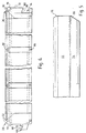
- Figure 1 illustrates a frame across which woven wire meshes are to be stretched and bonded in the manner herein described.
- the frame is generally designated 10 and includes a large number of similarly sized rectangular openings, one of which is denoted by 12 formed by a rectilinear matrix of orthogonally intersecting cross-members one of which is designated by 14 and another of which is designated by reference numeral 16.
- the frame On two opposite sides, namely 18 and 20, the frame includes a relatively wide flange the upper surface of which is corrugated so as to form ridges and furrows 22.
- the other two edges 24, 26 and 28 are relatively narrow and include just two or three ridges 30, 32.
- the plastics material By allowing the plastics material to cool, so the wire meshes will be held firmly in place and if they are tensioned in both directions prior to the heating step and the tensions are maintained throughout, thereafter the plastics material has cooled, residual tensions will remain in the stretched layers of wire cloth. If as is usually preferred, the wire cloths have been differentially tensioned so that the tension in one is higher than that in the other, the differential will remain in the residual tensions retained in the wire cloths.
- the first wirecloth will have a mesh size of approximately 30 and the second cloth a mesh size in the range 100-300.
- Each is made from annealed stainless steel wire - that making up the first cloth typically having a diameter of the order of 0.28mm.
- the frame is formed from a plastics material which may be reinforced with glass fibres or similar reinforcing material and the edge regions and the crossing members of the frame are all reinforced with elongate steel wires which are welded together to form a wire frame reinforcing structure in a manner which will be described later.
- steel wire of 2.5mm diameter is used to construct the reinforcing wire frame.
- a frame such as shown in Figure 1 is typically formed by inserting the reinforcing framework into a suitable mould tool and injecting plastics material under pressure into the tool so that the wire reinforcing frame becomes completely encased within plastics material (typically reinforced with glass fibre) so that on release from the mould, the reinforcing wires are totally encased within plastics material.
- plastics material typically reinforced with glass fibre
- the section at CC in Figure 2 shows the cross member 14 in section and the orthogonal cross member 16 is seen extending on either side of 14.
- the edge regions 18, 20 are reinforced by frame members 34 and 36.
- Ridges such as 24 in the upper surface of the relatively wide edge flange 20 can be seen, as can also the inner of the two ridges along the narrower edge 28, namely ridge 42 which is also identified in Figure 1 for reference purposes.
- the ridged end 28 is cut away at opposite ends at 44, 46 as shown in Figure 1.
- Two rods designated 48 and 50 extend through the upper and lower regions respectively of the cross member 38.
- each of the orthogonally extending cross members designated 14 and 52 respectively extend two similar pairs of rods designated 54 and 56, and 58 and 60 respectively. At the points of intersection between the rods they are welded together as by electric resistance welding.
- the extensions of the lower rods such as 50 are bent upwardly as shown at 66 so as to extend co-extensively with or in contact with the underside of the upper rod of the pair eg extension of rod 48 and are resistance welded thereto.
- the upper layer of intersecting and welded rods such as 48, 54, 58, 62, 64 is secured to the lower layer of rods such as 50, 56, 60, to form a unitary reinforcing structure.
- Figure 4 is a part section on AA to a larger scale than Figure 1 which allows the ridges 30 and 32 to be seen in section at the ends of the frame which are to be butt-joined.
- Figure 4 also shows detail of the male and female locking arrangement at opposite ends of the frame.
- an elongate protrusion 68 stands off from the left hand end face 70 and extends across the entire width of the frame, whilst at the other end of the frame the end face 72 is cutaway to define a rebate 74 to receive the protrusion 68 of an abutting frame.
- the end face 72 also includes an upstand 76 which cooperates with the opposite end region of the end face 70 of the abutting frame, to space the two end faces from each other by the thickness of the upstand 76. This also assists in seating the rebate 78 in the protrusion 68 correctly below the lp 80 along the upper edge of the rebate 74.
- Figure 4 also shows the small openings which can be left above the intersection point of the reinforcing grid, if stand-off pits, or stools, are used in the mould tooling to position the reinforcing grid within the tooling. Two of these are visible at 82 and 84.
- Figure 5 is a part end view in the direction of arrow D in Figure 1 and shows the upstand 76 and the end face 72 of the right hand end of the frame as depicted in Figure 4. Likewise the lip 80 is also shown together with the undercut 86 in the underside of the shoulder created by the rebate 74.
- Figure 6 shows how two frames 10 and 10' each similar to that shown in Figure 1 can be joined, with the two edges 26', 28 abutting/engaged as will be described more fully with reference to later figures of the drawings.
- the wider flanges 18 and 20, 18' and 20' and one end flange 28' are gripped in an appropriate manner within the basket of a shaker assembly.
- the end flange 20 may in fact only be supported on its underside in order to permit solids material to progress over that edge unimpeded during shaking.
- An inflatable grip seal may be used along the edges 20, 20', 28', 18' and 18.
- the two frames 10 and 10' may be aligned and in some shakers advantageously the aligned frames are mounted so as to be inclined to the horizontal so as to describe an uphill slope up which the mud which is to be filtered climbs as a result of the shaking movement.
- the shaking movement has components generally in the direction of the alignment of the two frames and generally perpendicular thereto.
- Figure 9 shows the edge 28 which includes the protruding nose generally designated 68 which extends across the width of the frame and fits below the shoulder 80, of the rebate 74 of the cooperating frame 10.
- the upstand 76 may comprise a separate member in the form of a seal which may be of plastics material or rubber or a composite thereof. Alternatively as shown it may simply comprise a protruding ridge formed during moulding, in the material from which the rest of the frame is constructed.
- frame 10' When mounting the two frames in a shaker, frame 10' is first introduced into the shaker basket and thereafter frame 10.
- the nose 68 By raising the right hand end of frame 10 (as viewed in Figure 6) so that the frame 10 is angled relative to the plane of frame 10', the nose 68 can be inserted below the shoulder 80 into the undercut 86 of the rebate 74 so that the ridge 88 of the protrusion 68 engages in the undercut 86 behind the shoulder 80.
- the frame 10 can be lowered so as to be in alignment with 10' and by choosing the dimensions carefully, in that condition only, the inclined surface 90 engages the inclined underside 92 and the upstand 76' makes contact with the face 70 of the other frame end. This is more clearly shown in Figure 10.
- the two screens such as shown in Figure 6, (each formed by a frame with woven meshes stretched thereover) are inclined relative one to the other instead of being aligned as shown in Figure 7.
- an alternative edge configuration may be incorporated, by arranging that one frame end can be fitted into the other with a small step between the two upper surfaces.
- Figure 11 is a plan view of such a frame.
- Figures 12, 13 and 14 provide edge and section views to an enlarged scale of the case of Figure 14, of the frame shown in Figure 11.
- Each of the intersecting cross members is ridged along its upper edge as best seen from the hidden detail of items 110, 112 in Figure 14.
- the ridges are identified by reference numerals 114, 116 and it will be noted that the peaks of the ridges 114, 116 are just below the peak of the ridges 118 along edge 106 (see Figure 11). This ensures that when the GRP material is heated to accommodate the wire meshes, the heating and welding of the meshes to the outer regions 100 to 106 of the frame occurs prior to that over the central region made up of intersecting cross members 108, 110 etc.
- the ends 104, 106 are designed to be capable of interengagement and accordingly the end 106 is formed with a pair of jaws 120, 122 which extend across the entire width of the frame end and can receive the opposed end 104 of a second frame (not shown).
- This opposed end comprises an extended flange 124 having three ridges 126 formed in its upper surface, the height of the flanges combined with the thickness of the flange 124 being equal to the internal spacing between the upper and lower jaws 120, 122, so that an end 124 can be pushed into the elongate slot formed by a pair of jaws 120, 122.
- the underside of the upper jaw diverges upwardly away from the lower jaw, to assist in entering the end 124 therein.
- the ridges 126 are deformable, and by dimensioning the gap between the jaws 120, 122 accurately, so the flange 104 can become firmly wedged in the gap between those jaws, the ridges 126 forming a partial seal between the flange 124 and the underside 128 of the upper jaw 120 of end flange 106.
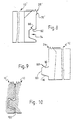
- the frame of Figure 11 includes a grid of reinforcing rods, welded or otherwise joined at the interstices of the grid, and constructed from upper and lower layers - generally designated 130, 132 respectively - see Figure 15.
- the ends of the lower layer of rods are bent upwardly as at 134 in Figure 16 to be welded to the aligned rods of the upper layer in the end flange 104.
- the two edges 100 and 102 are reinforced in the same way as is end flange 104, and the ends of the rods 136 of the lower layer are bent upwardly as at 138 in Figure 17, to merge with and be welded or otherwise joined to the upper rods 140.
- All the rods are wholly contained within the rectilinear array of intersecting cross members except at the flanged edges of the frame.
- Figure 18 shows how two frames such as shown in Figures 11 to 17 can be fitted so that one lies at a shallow angle relative to the other.
- the one frame is denoted 14.
- Figure 18A shows a modified interengagement possibility similar to the engagement of an end such as 126 in an elongate "socket" between jaws such as 120, 122 - but in which both ends are "female” (ie equivalent to end 106), and the upper flange of the one can be received and wedged, into the socket of the other and a good seal is maintained.
- Similar reference numerals are employed to denote items in common as between Figure 18A and earlier and later figures.
- plastics support inserts or stools such as denoted by 142, 144 may be located in the mould tool so as to engage the interstices of the intersecting rods, thereby to correctly space the framework within the mould tool when the latter is closed.
- the spacing and positioning may be achieved by fingers protruding from the inside surfaces of the mould tool, and any openings in the plastics moulding may be filled by appropriate material after the tool has been opened and the moulded component has been removed, or may be filled by the plastics material from which the struts are formed when the frame is subjected to heat and pressure during the manufacturing process.
- Preferred arrangements utilise stand-off supports or stools since these can be used not only to centre the reinforcing framework within the mould tool, but where the framework has been constructed so as to bow slightly upwardly and downwardly, they will redefine the correct spacing between the upper and lower arrays of rods, when the mould tooling is closed.
- stand-off supports or stools A preferred form of such stand-off support is illustrated and described with reference to Figures 19 to 23.
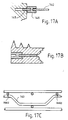
- spacers 143 In order to prevent moulding pressure within the tooling from forcing the upper and lower walled arrays of rods/wires together so as to reduce the spacing therebetween, spacers 143 (typically bent wires, formed to one or other of the two arrays and permitting relative movement towards each other beyond a critical dimension defined by the spacers) are provided, as shown in Figure 17C.
- plastic ferrules such as that shown in Figure 17 and denoted by 146, can be inserted into the mould tool so as to cover the ends of the rods which might otherwise be left exposed.
- the welded reinforcing framework is supported in one part of the tooling by four retractable pins (145), two on opposite sides of the framework, by means of double ended plastics ferrules (146) which are each fitted at one end onto an end of one of the rods (140) making up the framework, and at the other end onto one of the retractable pins.
- the pins (145) are retracted from the blind holes in the ferrules (146) which will have been embedded in the GRP during moulding, to permit the moulded article to be removed from the tooling.
- support inserts or ferrules protrude after moulding, they can be removed by cutting or filing.
- the crests of the ridges in the edge flanges of the frame shown in Figures 1 to 10 may also lie in a different plane from the crests of the ridges on the cross members such as 14 and 16, and in a preferred arrangement one or more of the outer ridges along the flanges such as 18, 20, 26 and 28 extend(s) above the plane containing the crests of the crests of the cross members such as 14, 16.
- the peripheral regions of the frames contain a greater amount of plastics material to be heated and softened before the woven wire mesh cloth can be forced thereinto, than exists along the cross-members. Bonding of the peripheral regions therefore has to occur before the cloths can come into contact with, and become bonded into the crests of the cross members 14, 16 etc.
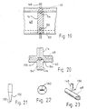
- FIGs 19 to 23 show, to different, and generally an enlarged scale, the location of preferred stand off supports for the reinforcing rods.
- each support comprises a tapering chisel-ended metal pin 148 as shown in Figure 19.
- the chisel end 150 is best seen in Figure 21.
- each chisel end 150 extends generally perpendicularly to the length dimension of the rod 48 which it will engage in the mould tool.
- Figure 24 is a perspective view of the female end of the frame 10' of Figure 9.
- the sealing ridge 76 can be seen above the groove 74 into which the elongate male "nose” 68 (see Figure 9) fits.
- the crests of the plastics frame will soften and allow the wire cloths to sink into the crests, which will also become flattened into the process.
- the plastics material hardens and secures the wire cloths in place.
- the crests of the outermost ridges 160 on the flange extend upwardly above the crests of the inner ridges of the same flange.
- the land area at the junction between two screens such as shown in Figures 7 and 18 should be as small as possible so as not to impede the progress of particulate material from one screen to the next.
- the front edge of the screen where solids traverse over and off the edge, for example into a skip should also be as small in area as possible.
- the joint provided by the engagement such as shown in Figures 18, 18A also seals the joint and prevents fluid leakage, and has been found to reduce the risk of bounce between one frame and the other across the joint. This appears to be achieved due to the formation of a structural member by the reinforcing wires and where these are tensioned, as is the case when the framework is pushed from above and below in the mould tool, the framework and plastics material will significantly resist bending and therefore minimise any tendency to bounce.
- Flash heating is preferably used to bond the wire cloths to the crests.
- Weld wires are conveniently employed between overlying parallel rods such as 48, 66 (see Figure 3) as designated by reference numeral 49.
Abstract
Description
- This invention concerns screens for use as filters in vibratory filtration equipment such as shakers that are used in the oil drilling industry for separating solids from the liquid phase of oil and water based muds retrieved from drilling operations. In particular the invention is concerned with the construction and manufacture of support frames over which filtering material such as woven wire cloth is stretched and secured to form the screens and to the re-use of such frames.
- Examples of filtering machines in which such screens are used are contained in UK 2237521 and UK 2229771.
- One such screen is described in PCT/GB95/00411 (W095/23655).
- The earlier design of screen extends the life of a screen by providing a sacrificial support cloth of woven wire below an upper woven wire cloth of harder wearing material than that of at least the surface of the wire from which the lower cloth is woven, so that wear due to rubbing and vibration during use occurs to a greater extent in the lower cloth than in the upper cloth. The specification also describes an improved design of frame across which woven wire cloths can be tensioned and bonded by adhesive, to form a sifting screen, in which the frame is proposed to be formed from glass reinforced gas blown polypropylene with elongate metal reinforcing elements or rods buried in the GRP. The improved frame construction is shown in Figures 3 to 8 of the earlier specification.
- It is an object of the present invention to provide an improved method of constructing such a frame and an improved frame for use as the support for layers of woven wire cloth, an improved screen formed from such a frame, and a frame which can be re-used under some circumstances.
- According to one aspect of the invention, a method of constructing a polymer support frame over which woven wire cloth is to be stretched and secured to form a sifting screen comprises the steps of locating in a mould tool a wire frame assembly comprising two parallel spaced apart arrays of reinforcing wires, closing the tool, injecting liquid polymer so as to wholly encapsulate the wire frame and to form an article having an open central region criss-crossed by intersecting orthogonal ribs bounded on all sides by a rigid flange, in which each of the ribs includes two parallel spaced apart wires of the said wire frame assembly, permitting the polymer to cure, and opening the tool, and removing the moulded article.
- By arranging for two parallel spaced apart wires to extend through each of the ribs, one near one edge and the other neaer to the opposite edge of the rigs, each rib has the stiffness of a beam, and the resulting frame has high rigidity and resistance to bending, yet remains relatively lightweight.
- Preferably the wire frame is selected so as to impart sufficient structural rigidity to the support frame as to prevent deflection thereof and consequent changes in the tension in the wire cloth when fitted thereto.
- Additionally the wire frame is selected so as to impart sufficient strength to the support frame as to allow the latter to withstand shear stresses introduced as the frame is clamped into a vibratory screening machine.
- Typically the wire frame is formed from high tensile straightened steel wire, bent as required, and in a preferred arrangement the wire is of 2.5mm diameter.
- Preferably the wire frame fabrication is assembled so that each matrix is bowed in an outward sense, opposite to the other.
- During moulding it has been found that the pressure within the mould tool can distort the framework so that the outward bowing of the opposite faces of the framework can be replaced by significant inward bending - so destroying the alignment of the long rods within the upper and lower edges of the interstices of the moulded frame. To avoid this it is proposed that at least one spacer is located within the framework, so that if there is any tendency for the rod arrays to collapse inwards, the spacer will present this collapse occurring.
- Preferably a plurality of spacers are located within the wire frame fabrication, each attached to one or other of the matrices so as to extend towards the other, whereby any tendency for the matrices to collapse inwards during moulding, is resisted by the spacers.
- In one embodiment each spacer comprises a length of wire bent to form a shallow U with its two ends bent outwards to form two in-line lugs by which it can be welded to the underside of one of the wires which form one of the matrices, with the crest of the U section in close proximity to one of the wires of the other matrix, whereby the spacer will maintain a given dimension between the two matrices if the fabrication is subjected to a collapsing force during moulding, so causing the crest to engage the said wire of the other matrix.
- The invention also provides a method of moulding a support frame in a mould tool as aforesaid around a wire frame fabrication as aforesaid wherein an inward force is exerted on opposite faces of the fabrication within the mould tool by fingers protruding inwardly from the inside faces of the tool, to externally engage the opposite matrices of the fabrication when the tooling closes.
- In accordance with this method, the fingers sandwich the fabrication in position and produce just the required inward movement of the two oppositely bowed matrices to render them parallel and spaced apart by the desired distance.
- Typically the fingers comprise inwardly projecting pegs which align with crossing points of wires in the upper and lower reinforcing matrices, to space the matrices from the corresponding upper and lower internal surfaces of the mould tool and ensure that the matrices are buried within the plastics material which is injected into the mould tool during the manufacturing process.
- Preferably the ends of the pegs taper to an edge, or a point.
- After the mould tool is opened and the protruding pegs disengage from the struts, openings are left in the polymer. Preferably therefore the method further comprises plugging the openings with plastics material or filler.
- Typically the wire frame fabrication is supported within the tooling by means of retractable pins which protrude through the tooling wall to engage the fabrication and accurately locate it within the tooling.
- The pins may be retracted as the tooling opens after the moulding step has been completed.
- Conveniently the pins align with protruding ends of wires making up the fabrication and are separably joined to the ends of the wires by means of sleeves of plastics material opposite ends of which receive the pins and the reinforcing wire ends respectively.
- Preferably the passage through each sleeve is blocked so as to form two coaxial blind bores, and each sleeve becomes embedded in the polymer during moulding and remains in the polymer as the pin which engages it is retracted as the tooling is opened, the blocked passage serving to encapsulate the end of the wire end located in the inner end of the sleeve.
- Prior to moulding the tool may be fitted with pegs formed from a plastics material which is compatible with or is the same as the polymer material which is to be injected into the mould to encapsulate the wire frame fabrication, and the pegs become integrally bonded therein during moulding so that when the tool is opened, the pegs separate from the tool, and remain in the frame.
- Protruding portions of each peg may be removed by grinding or filing or cutting.
- The invention thus provides a support frame of polymer material having wire reinforcing therein and to which woven wirecloth is to be bonded to form a filtering screen, in which the frame is constructed as aforesaid.
- It is of course necessary to select a plastics material which is suitable to serve as a bonding medium for woven wire cloth and it has been found that polypropylene and polyethylene are suitable plastics materials although the invention is not limited to the use of polypropylene and polyethylene.
- Whether polyethylene or polypropylene is used, it has been found advantageous for either material to be gas blown and glass fibre reinforced.
- In a preferred arrangement, the wirecloth which is first fitted over the support frame has a coarser mesh than any subsequent layer of wirecloth fitted thereover.
- According to a preferred feature of the invention, in a support frame which is formed from glass reinforced plastics material, the faces of the peripheral edge regions of the support frame which woven wirecloth is to overlay and to which the cloth is to be bonded by heating, are formed with a plurality of closely spaced apart parallel ridges so that when the surface is heated, the crests of the ridges soften, and woven wirecloth laid thereover and tensioned can, under an appropriate downward loading, penetrate and become embedded in the softened crests.
- In a support frame as aforesaid, which is generally rectangular, the ridges along each of the four sides run parallel to the length dimension of each side so that the ridges in the surfaces of the four edges of the frame run perpendicular to the direction in which woven wirecloth is tensioned relative to those edges.
- Preferably sufficient plastics material exists in each of the struts between the internal wire reinforcement therein and the cloth engaging surface thereof, to enable the strands of wire forming the wirecloth also to become embedded in the struts when the frame is heated and an appropriate force is applied, without the wirecloth contacting the internal reinforcing wires, to prevent electolytic action between wirecloth and reinforcing wires where different metals are used.
- According to another preferred feature of the invention, in a support frame as aforesaid, constructed from glass fibre reinforced plastics material over which wirecloth is to be stretched and bonded thereto to form a sifting screen and which includes a matrix of struts within a perimeter flange of the frame, the thickness of the cloth engaging ends of the struts is less than that of the more remote regions of the struts.
- Preferably the wirecloth engaging edge of each strut is of reduced section, and on heating the wirecloth wires become embedded in the said reduced strut sections.
- The reduced strut section is preferably created by forming a ridge along the wire receiving edge thereof.
- Preferably the moulding process forms an outer peripheral flange surrounding a central region occupied by an integral matrix of interconnecting struts wherein the flange and struts are ridged where they are to engage the wirecloth and the ridges extend to different heights so that the crests lie in different parallel planes.
- Preferably the crests of the ridges of the struts defining the integral matrix lie in a first plane, which is below a second plane containing the crests of the ridges on the surrounding flange.
- In such a support frame, outer ridges on some or all of the surrounding flange may extend to a greater height than inner ridges on the flange, so that the crests of the outer ridges occupy a third plane above the second plane, whereby there is a greater volume of polymer to be melted and spread by the application of heat and pressure to the wirecloth near the outer edges of the peripheral flange, than is the case near the inner regions of the flange.
- By forming ridges along the wire cloth engaging edges of the struts, so the area of the woven wire cloth which is actually blinded by being embedded in plastics material is reduced to the minimum necessary to achieve support for the cloths. Thus although the struts may have a lateral width considerably greater than the width of their crests, the area of the woven wire cloth which is available for filtering liquid is only reduced by the narrow width of the melted crests and is not reduced by the total area of the struts, which would be the case if the width of the cloth engaging face of the struts is the same width as the struts themselves.
- The ridged struts may have a symmetrical cross-section in which the crest is mid-way between two parallel sides of the strut, and the ridge can be thought of as an isosceles triangulation at the upper end of a rectangular cross-section of the remainder of the strut. However this configuration is merely a preferred form, and the triangular cross-section of the upper region of the strut may be offset so that the crest of the ridge is displaced towards one side or the other of the strut when viewed end on and if the triangle is a right angled triangle the crest will be aligned with one side or the other of the rectangular section of the strut, the hypotenuse of the triangle forming a sloping surface between the crest of the ridge and the other edge of the rectangular strut region.
- In general the primary purpose of the ridging of the struts is to reduce the width of the plastics material which is to engage the woven wire cloth, and the ridging effect can be obtained simply by reducing the width of the strut just below its face which is to be bonded to the wire cloth. This width reduction may be achieved by means of a step, so as to define a shoulder, (or two steps on opposite sides to form two shoulders), and the reduced width region above the shoulder(s) provides the reduced width plastics face for engaging the woven wire cloth. The difference between such an arrangement and a triangular ridge is that in the former case, the underside of the woven wire cloth immediately to the left or right of a bonded crest will be completely unobstructed at least down to the shoulder(s) whereas in the case of a triangular ridge, a sloping surface will be presented to liquid filtering through the wire cloth. In practice however, the stronger triangular section is preferred particularly since differential softening will occur down the height of the ridge upon the application of heat to the crests.
- Preferably the overall shape of the frame is a rectangle, and the flange which extends along the two longer sides is wider than the flange along the two shorter sides, and at least one of the shorter sides is adapted to be joined to the corresponding shorter side of a similar screen support frame, constructed in the same way as the first.
- Preferably one of the shorter ends of the frame is adapted to interlock and sealingly engage with a corresponding edge of an adjoining similar support frame such that if the two frames are slid the one towards the other, engagement and sealing occurs merely by the sliding movement of the one frame relative to the other.
- The sealing engagement of one frame to the other can be arranged to occur when the two frames are in line, or when the two frames are mutually angled.
- It is an advantage to form screens in this way and to mount a number of such screens in a supporting framework within a vibratory screening machine with edges abutting so as to form a larger area for filtering, for a number of reasons.
- Firstly, as already indicated, some designs of shaker require a first filtering area to be substantially horizontal and a second area to be inclined upwardly in the direction of particulate movement over the overall screen. This can be achieved by forming the overall screen from two smaller screens, each constructed as aforesaid and adapted to be joined edge to edge where the change in inclination is required to occur.
- Secondly, each individual screen can be of such a size and weight as can be readily handled by one man.
- Thirdly in the event of damage occurring in one such screen, it can be simply removed and a fresh screen inserted (sometimes without needing to disturb the undamaged screen(s)).
- In a support frame as aforesaid, preferably the cross section of each strut is generally rectangular and the longer dimension is generally perpendicular to the plane of the frame, and a first reinforcing wire extends through each strut near the edge thereof which is to be bonded to wirecloth, and a second parallel reinforcing wire extends through each strut near to the opposite edge thereof, and the wires are bonded to the plastics material by the moulding step and form therewith a beam, thereby to impart rigidity to the structure.
- Preferably the struts intersect similar struts which extend at right angles and a second assembly of parallel reinforcing wires is provided, running perpendicular to the first assembly of wires in planes proximate those containing the first said assembly, so that a pair of parallel spaced apart wires extends through each of the struts.
- In such a support frame each reinforcing wire which aligns with the peripheral flange of the frame preferably extends into the flange at each end thereof, thereby to increase the rigidity of the flange.
- Preferably the ends of the other wire of each pair are bent so as also to become aligned with the flange of the frame, and the bent ends thereof extend into the said flanges close to the ends of the first mentioned wire to further assist in reinforcing the said flanges.
- Typically the wires touch at all points of intersection and are preferably welded at all such points.
- Preferably the ends of each pair of wires are welded where they occupy the flange.
- In a wireframe assembly for a support frame as aforesaid, cross-point engagement may be introduced between parallel wires in the flange by incorporating intermediate transversely extending filler wire, or weld wire, between the wire ends.
- Further reinforcing may be provided in the flange by means of additional reinforcing wires extending parallel to the length direction of the flange so as to overlie or underlie the protruding reinforcing wires entering the flange from the struts, and the additional reinforcing wires are welded to the protruding reinforcing wire ends.
- Filtering machines of the type into which screens as aforesaid can be fitted, are described in UK Patent Specifications Nos. 2237521 and 2299771, but these are intended as examples only and the invention is not limited to the use of these screens in such machines.
- The invention will now be described by way of example, with reference to the accompanying drawings, in which:
- Figure 1 is a plan view of a frame over which wire cloths are to be stretched and secured to form a screen for use a filter in a vibratory filtration equipment such as a shaker for separating solids from the liquid phase of oil and water based muds;
- Figure 2 is a cross-sectional view at CC of Figure 1;
- Figure 3 is a part section at BB in Figure 1;
- Figure 4 is a part section on AA in Figure 1;
- Figure 5 is a part end view at D of the frame of Figure 1 to an enlarged scale;
- Figure 6 is a plan view to a reduced scale showing two screens, each constructed using a frame such as shown in Figure 1, in aligned edge abutting relation, to form a larger screening area;
- Figure 7 is a side elevation in the direction of arrow VII of Figure 6;
- Figures 8 or 9 show to an enlarged scale the two inter-engaging edge regions of the two frames of Figures 6 and 7;
- Figure 10 shows to enlarged scale in cross-section the abutting region of the two frames shown circled at VIII in Figure 7;
- Figure 11 is a plan view from above of another frame similar to that of Figure 1, but adapted to be joined in edge abutting relation with another similar frame so that the two frames are angled relative to one another when viewed from the side;
- Figure 12 is an end view at "B" in Figure 11;
- Figure 13 is a section on DD in Figure 11;
- Figure 14 is a part end view (to an enlarged scale) at "B" in Figure 11;
- Figure 15 is a part section at AA of the left hand end of the frame shown in Figure 11;
- Figure 16 is a part section at AA of the right hand end of the frame of Figure 11 showing in more detail the wire reinforcing structure, and where inserts are required to support it within a mould tool;
- Figure 17 is a part section at CC (to an enlarged scale) of the frame of Figure 11;
- Figures 17A and 17B show how the wire frame can be supported within a mould tool by ferrules which become an integral part of the moulded frame to cover the ends of the wires;
- Figure 17C shows a bent-wire spacer to prevent wireframe collapse in the mould tool, as polymer is injected under pressure.
- Figure 18 is a side edge view of two frames of the type shown in Figure 11, in edge abutting engagement;
- Figure 18A is a view of the join to an enlarged scale;
- Figure 19 is a side elevation partly in cross-section of an intersection between row and column support members of a frame such as shown in Figure 1;
- Figure 20 is a top plan view of the frame part shown in Figure 19;
- Figure 21 is an elevation of a support for locating the wire reinforcing structure at a point of intersection as shown in Figures 19 and 20;
- Figure 22 is an end view to an enlarged scale of the lower end of the support of Figure 21;
- Figure 23 shows to a larger scale the preferred engagement of the chisel end of the stand off support with a reinforced rod; and
- Figure 24 shows part of a completed screen.
-
- Figure 1 illustrates a frame across which woven wire meshes are to be stretched and bonded in the manner herein described. The frame is generally designated 10 and includes a large number of similarly sized rectangular openings, one of which is denoted by 12 formed by a rectilinear matrix of orthogonally intersecting cross-members one of which is designated by 14 and another of which is designated by
reference numeral 16. - On two opposite sides, namely 18 and 20, the frame includes a relatively wide flange the upper surface of which is corrugated so as to form ridges and furrows 22. The other two
edges ridges - By forming similar ridges along the top of each of the orthogonal cross-members, and arranging that the ridges of the cross-members are engaged by the wire cloth after the latter have become embedded in the ridges of the surrounding flanges, by heating over the whole surface area of the frame, so the woven wire meshes will become secured to the crests of the crossing members which when the assembly cools, will hold the woven wire cloths firmly in place, and provide additional support therefor.
- In a typical example, the first wirecloth will have a mesh size of approximately 30 and the second cloth a mesh size in the range 100-300. Each is made from annealed stainless steel wire - that making up the first cloth typically having a diameter of the order of 0.28mm.
- In accordance with a preferred aspect of the invention, the frame is formed from a plastics material which may be reinforced with glass fibres or similar reinforcing material and the edge regions and the crossing members of the frame are all reinforced with elongate steel wires which are welded together to form a wire frame reinforcing structure in a manner which will be described later. Typically steel wire of 2.5mm diameter is used to construct the reinforcing wire frame.
- A frame such as shown in Figure 1 is typically formed by inserting the reinforcing framework into a suitable mould tool and injecting plastics material under pressure into the tool so that the wire reinforcing frame becomes completely encased within plastics material (typically reinforced with glass fibre) so that on release from the mould, the reinforcing wires are totally encased within plastics material.
- The section at CC in Figure 2 shows the
cross member 14 in section and theorthogonal cross member 16 is seen extending on either side of 14. Theedge regions frame members - The cross-section at BB in Figure 1 is shown in Figure 3. The
cross member 14 is still visible but theorthogonal cross member 38 is now shown intersecting 14 and the opening intersected by BB is denoted 40. - Ridges such as 24 in the upper surface of the relatively
wide edge flange 20 can be seen, as can also the inner of the two ridges along thenarrower edge 28, namelyridge 42 which is also identified in Figure 1 for reference purposes. Theridged end 28 is cut away at opposite ends at 44, 46 as shown in Figure 1. - Also shown in Figure 3 are some of the metal reinforcing rods forming the reinforcing framework. Two rods designated 48 and 50 extend through the upper and lower regions respectively of the
cross member 38. - Similar pairs of rods extend through the upper and lower regions of each of the parallel cross members such as 16.
- Through each of the orthogonally extending cross members designated 14 and 52 respectively, extend two similar pairs of rods designated 54 and 56, and 58 and 60 respectively. At the points of intersection between the rods they are welded together as by electric resistance welding.
- Further reinforcing
rods rods edge region 20, and this is resistance welded to the extended ends of therods 48 etc where they extend into theflange 20. - The extensions of the lower rods such as 50 are bent upwardly as shown at 66 so as to extend co-extensively with or in contact with the underside of the upper rod of the pair eg extension of
rod 48 and are resistance welded thereto. In this way the upper layer of intersecting and welded rods such as 48, 54, 58, 62, 64 is secured to the lower layer of rods such as 50, 56, 60, to form a unitary reinforcing structure. - Figure 4 is a part section on AA to a larger scale than Figure 1 which allows the
ridges - Figure 4 also shows detail of the male and female locking arrangement at opposite ends of the frame. Thus at the left hand end an
elongate protrusion 68 stands off from the lefthand end face 70 and extends across the entire width of the frame, whilst at the other end of the frame theend face 72 is cutaway to define arebate 74 to receive theprotrusion 68 of an abutting frame. - The end face 72 also includes an
upstand 76 which cooperates with the opposite end region of theend face 70 of the abutting frame, to space the two end faces from each other by the thickness of theupstand 76. This also assists in seating the rebate 78 in theprotrusion 68 correctly below thelp 80 along the upper edge of therebate 74. - Figure 4 also shows the small openings which can be left above the intersection point of the reinforcing grid, if stand-off pits, or stools, are used in the mould tooling to position the reinforcing grid within the tooling. Two of these are visible at 82 and 84.
- Figure 5 is a part end view in the direction of arrow D in Figure 1 and shows the
upstand 76 and theend face 72 of the right hand end of the frame as depicted in Figure 4. Likewise thelip 80 is also shown together with the undercut 86 in the underside of the shoulder created by therebate 74. - Figure 6 shows how two
frames 10 and 10' each similar to that shown in Figure 1 can be joined, with the twoedges 26', 28 abutting/engaged as will be described more fully with reference to later figures of the drawings. - In use the
wider flanges end flange 20 may in fact only be supported on its underside in order to permit solids material to progress over that edge unimpeded during shaking. - An inflatable grip seal may be used along the
edges - As shown in Figure 7, the two
frames 10 and 10' may be aligned and in some shakers advantageously the aligned frames are mounted so as to be inclined to the horizontal so as to describe an uphill slope up which the mud which is to be filtered climbs as a result of the shaking movement. Typically the shaking movement has components generally in the direction of the alignment of the two frames and generally perpendicular thereto. - The two separate parts forming the abutment are shown to an enlarged scale in Figures 8 and 9, and detail of the engagement is shown in Figure 10. Figure 9 shows the
edge 28 which includes the protruding nose generally designated 68 which extends across the width of the frame and fits below theshoulder 80, of therebate 74 of the cooperatingframe 10. - The
upstand 76 may comprise a separate member in the form of a seal which may be of plastics material or rubber or a composite thereof. Alternatively as shown it may simply comprise a protruding ridge formed during moulding, in the material from which the rest of the frame is constructed. - When mounting the two frames in a shaker, frame 10' is first introduced into the shaker basket and thereafter frame 10. By raising the right hand end of frame 10 (as viewed in Figure 6) so that the
frame 10 is angled relative to the plane of frame 10', thenose 68 can be inserted below theshoulder 80 into the undercut 86 of therebate 74 so that theridge 88 of theprotrusion 68 engages in the undercut 86 behind theshoulder 80. Once 88 is within 86, theframe 10 can be lowered so as to be in alignment with 10' and by choosing the dimensions carefully, in that condition only, theinclined surface 90 engages theinclined underside 92 and the upstand 76' makes contact with theface 70 of the other frame end. This is more clearly shown in Figure 10. - By dimensioning thus any fluid trapped between the ends of the frame as the two frames are pushed together, can be squeezed through the gap left between the surfaces to facilitate drainage through the lowermost gap visible in Figure 10.
- In some shakers, it is preferred that the two screens such as shown in Figure 6, (each formed by a frame with woven meshes stretched thereover) are inclined relative one to the other instead of being aligned as shown in Figure 7. To this end an alternative edge configuration may be incorporated, by arranging that one frame end can be fitted into the other with a small step between the two upper surfaces.
- Figure 11 is a plan view of such a frame.
- Figures 12, 13 and 14 provide edge and section views to an enlarged scale of the case of Figure 14, of the frame shown in Figure 11.
- Essentially the construction of the central area of the frame is similar to that of the frame of Figure 1. Thus the meshes are secured to
external flanges - The relatively
wide flanges cross members - Each of the intersecting cross members is ridged along its upper edge as best seen from the hidden detail of
items reference numerals ridges ridges 118 along edge 106 (see Figure 11). This ensures that when the GRP material is heated to accommodate the wire meshes, the heating and welding of the meshes to theouter regions 100 to 106 of the frame occurs prior to that over the central region made up of intersectingcross members - The ends 104, 106 are designed to be capable of interengagement and accordingly the
end 106 is formed with a pair ofjaws opposed end 104 of a second frame (not shown). This opposed end comprises anextended flange 124 having threeridges 126 formed in its upper surface, the height of the flanges combined with the thickness of theflange 124 being equal to the internal spacing between the upper andlower jaws end 124 can be pushed into the elongate slot formed by a pair ofjaws - At 128 the underside of the upper jaw diverges upwardly away from the lower jaw, to assist in entering the
end 124 therein. Being formed from a plastics based material, theridges 126 are deformable, and by dimensioning the gap between thejaws flange 104 can become firmly wedged in the gap between those jaws, theridges 126 forming a partial seal between theflange 124 and theunderside 128 of theupper jaw 120 ofend flange 106. - As with the frame illustrated in Figures 1 to 10, the frame of Figure 11 includes a grid of reinforcing rods, welded or otherwise joined at the interstices of the grid, and constructed from upper and lower layers - generally designated 130, 132 respectively - see Figure 15. The ends of the lower layer of rods are bent upwardly as at 134 in Figure 16 to be welded to the aligned rods of the upper layer in the
end flange 104. - The upper and lower layers of rods terminate without converging at the other end of the frame as can be seen from the part section of Figure 15.
- The two
edges end flange 104, and the ends of therods 136 of the lower layer are bent upwardly as at 138 in Figure 17, to merge with and be welded or otherwise joined to theupper rods 140. - All the rods are wholly contained within the rectilinear array of intersecting cross members except at the flanged edges of the frame.
- The part section of Figure 17 is taken on the line CC in Figure 11 and
cross members - Figure 18 shows how two frames such as shown in Figures 11 to 17 can be fitted so that one lies at a shallow angle relative to the other. The one frame is denoted 14.
- Figure 18A shows a modified interengagement possibility similar to the engagement of an end such as 126 in an elongate "socket" between jaws such as 120, 122 - but in which both ends are "female" (ie equivalent to end 106), and the upper flange of the one can be received and wedged, into the socket of the other and a good seal is maintained. Similar reference numerals are employed to denote items in common as between Figure 18A and earlier and later figures.
- As also shown in Figure 17, plastics support inserts or stools such as denoted by 142, 144 may be located in the mould tool so as to engage the interstices of the intersecting rods, thereby to correctly space the framework within the mould tool when the latter is closed.
- In an alternative spacing arrangement, the spacing and positioning may be achieved by fingers protruding from the inside surfaces of the mould tool, and any openings in the plastics moulding may be filled by appropriate material after the tool has been opened and the moulded component has been removed, or may be filled by the plastics material from which the struts are formed when the frame is subjected to heat and pressure during the manufacturing process.
- Preferred arrangements utilise stand-off supports or stools since these can be used not only to centre the reinforcing framework within the mould tool, but where the framework has been constructed so as to bow slightly upwardly and downwardly, they will redefine the correct spacing between the upper and lower arrays of rods, when the mould tooling is closed. A preferred form of such stand-off support is illustrated and described with reference to Figures 19 to 23.
- In order to prevent moulding pressure within the tooling from forcing the upper and lower walled arrays of rods/wires together so as to reduce the spacing therebetween, spacers 143 (typically bent wires, formed to one or other of the two arrays and permitting relative movement towards each other beyond a critical dimension defined by the spacers) are provided, as shown in Figure 17C.
- In a similar way, plastic ferrules such as that shown in Figure 17 and denoted by 146, can be inserted into the mould tool so as to cover the ends of the rods which might otherwise be left exposed.
- In a preferred mould tool, the welded reinforcing framework is supported in one part of the tooling by four retractable pins (145), two on opposite sides of the framework, by means of double ended plastics ferrules (146) which are each fitted at one end onto an end of one of the rods (140) making up the framework, and at the other end onto one of the retractable pins. After moulding, the pins (145) are retracted from the blind holes in the ferrules (146) which will have been embedded in the GRP during moulding, to permit the moulded article to be removed from the tooling.
- An example is shown in Figures 17A and 17B.
- Where support inserts or ferrules protrude after moulding, they can be removed by cutting or filing.
- As mentioned in relation to Figures 11 et seq, the crests of the ridges in the edge flanges of the frame shown in Figures 1 to 10 may also lie in a different plane from the crests of the ridges on the cross members such as 14 and 16, and in a preferred arrangement one or more of the outer ridges along the flanges such as 18, 20, 26 and 28 extend(s) above the plane containing the crests of the crests of the cross members such as 14, 16. In this way the peripheral regions of the frames contain a greater amount of plastics material to be heated and softened before the woven wire mesh cloth can be forced thereinto, than exists along the cross-members. Bonding of the peripheral regions therefore has to occur before the cloths can come into contact with, and become bonded into the crests of the
cross members - Figures 19 to 23 show, to different, and generally an enlarged scale, the location of preferred stand off supports for the reinforcing rods. Here each support comprises a tapering chisel-ended
metal pin 148 as shown in Figure 19. Thechisel end 150 is best seen in Figure 21. - As shown in Figure 23, the pins are arranged so that each
chisel end 150 extends generally perpendicularly to the length dimension of therod 48 which it will engage in the mould tool. - By virtue of the
chisel end 150, and thetaper 152, liquid plastic material flows around the tapering, chisel ends in such a way as to leave similarly tapering recesses such as 154 in the crests of the cross members of the frame when the tool is opened and the chisel ends are extracted from the moulding. Each recess left by apin 148 therefore only exposes atiny area 156 of the wire (see Figure 20). - When woven wire cloths are stretched over the crests of the frame and the cloths and frame are heated, the plastics material flows into the lower end of each recess left by a chisel end, such as 150. This fills the tiny area to provide a barrier between the wire mesh(es) and the reinforcing rods such as 48 (see Figure 3).
- Figure 24 is a perspective view of the female end of the frame 10' of Figure 9.
- The sealing
ridge 76 can be seen above thegroove 74 into which the elongate male "nose" 68 (see Figure 9) fits. - Across the frame are stretched woven wire cloths, the upper one of which is shown in part at 158 and the lower, in part, at 159. Two such cloths, one above the other, are stretched over the frame, the mesh of the lower cloth being coarser than that of the upper cloth, and with the tension in the lower cloth being greater than that in the upper.
- By heating at least the upper surface of the frame, and applying uniform downward pressure on the cloths, the crests of the plastics frame will soften and allow the wire cloths to sink into the crests, which will also become flattened into the process. On cooling the plastics material hardens and secures the wire cloths in place.
- The crests of the
outermost ridges 160 on the flange extend upwardly above the crests of the inner ridges of the same flange. - The land area at the junction between two screens such as shown in Figures 7 and 18 should be as small as possible so as not to impede the progress of particulate material from one screen to the next.
- Likewise the front edge of the screen where solids traverse over and off the edge, for example into a skip, should also be as small in area as possible.
- The joint provided by interfitting ends such as shown in Figures 18, 18A, causes the
edge 120 of the upper frame to overlie wire mesh of the lower frame. The non-screening dead area is thereby reduced to the minimum, ie theridged end 120. - The joint provided by the engagement such as shown in Figures 18, 18A also seals the joint and prevents fluid leakage, and has been found to reduce the risk of bounce between one frame and the other across the joint. This appears to be achieved due to the formation of a structural member by the reinforcing wires and where these are tensioned, as is the case when the framework is pushed from above and below in the mould tool, the framework and plastics material will significantly resist bending and therefore minimise any tendency to bounce.
- Flash heating is preferably used to bond the wire cloths to the crests.
- Weld wires are conveniently employed between overlying parallel rods such as 48, 66 (see Figure 3) as designated by
reference numeral 49. - The drawings and related description of UK Patent Specifications 2237521 and 2299771 are referred to as illustrating filtering machines of the type in which screens as described herein may be mounted.
Claims (10)
- A method of constructing a polymer support frame over which woven wire cloth is to be stretched and secured to form a sifting screen, the method comprising the steps of:(a) locating in a mould tool a reinforcing wire frame assembly comprising two parallel spaced apart arrays of reinforcing wires;(b) closing the mould tool;(c) injecting liquid polymer into the mould tool by injection moulding so as to wholly encapsulate the wire frame and to form an article having an open central region criss-crossed by intersecting orthogonal ribs bounded on all sides by a rigid flange, the article being such that each of said ribs includes two parallel spaced apart wires of said frame assembly;(d) permitting the polymer to cure;(e) opening the tool; and(f) removing the article.
- A method as claimed in claim 1, wherein an inward force is exerted on opposite faces of the wire frame assembly within the mould tool by fingers protruding inwardly from inside faces of the tool, said fingers being operable to engage the matrices when the tool closes.
- A method as claimed in claim 1 or 2 wherein the polymer is a glass-reinforced plastics material.
- A method as claimed in claim 3 wherein the faces of peripheral edge regions of the support frame over which woven cloth overlies and to which the cloth is to be bonded by heating are formed during manufacture with a plurality of substantially parallel ridges, the ridges being susceptible to soften on heating to bond onto the cloth laid thereover so that the cloth penetrates and becomes embedded in softened crests of the ridges.
- A method as claimed in claim 4, in which said edge regions include an outer peripheral flange surrounding a central region occupied by an integral matrix of interconnecting struts, the flange and struts are formed with ridges where they engage the wirecloths, and the ridges extend to different heights so that corresponding crests of the ridges lie in different parallel planes.
- A method as claimed in any of claims 1 to 5 wherein spacers are located within the wire frame assembly, each attached to one or other of the arrays of reinforcing wires so as to extend towards the other, whereby any tendency for the arrays to collapse inwards during moulding, is resisted by the spacers.
- A method as claimed in any of claims 2 to 6, wherein the fingers comprise inwardly projecting pegs which align with crossing points of wires in the upper and lower reinforcing matrices, to space the matrices from the corresponding upper and lower internal surfaces of the mould tool and ensure that the matrices are buried within the plastics material which is injected into the mould tool during the manufacturing process, and the ends of the pegs taper to an edge, or a point, and wherein after the mould tool is opened the protruding pegs disengage from the struts leaving openings in the polymer, and the method further comprises the step of plugging the openings with plastics material or filler.
- A method as claimed in any of claims 1 to 7 wherein the wire frame assembly is supported within the tooling by means of retractable pins which protrude through the tooling wall to engage the assembly and accurately locate it within the tooling, and the pins are retracted as the tooling opens after the moulding step has been completed.
- A method as claimed in claim 8 wherein the pins align with protruding ends of wires making up the wire frame assembly and are separably joined to the ends of the wires by means of sleeves of plastics material which is compatible with or the same as the polymer used to form the support frame, and opposite ends of the sleeves receive the pins and the reinforcing wire ends respectively, and wherein the passage through each sleeve is blocked so as to form two coaxial blind bores, each sleeve becomes embedded in the polymer during moulding and remains in the polymer as the pin which engages it is retracted as the tooling is opened, the blocked passage serving to encapsulate the end of the wire end located in the inner end of the sleeve.
- A method as claimed in claim 9 wherein prior to moulding the tool is fitted with the pegs, and the pegs become integrally bonded to the polymer material during moulding so that when the tool is opened, the pegs separate from the tool, and remain in the polymer support frame, and portions of each peg protruding from the support frame are removed by grinding or filing or cutting.
Applications Claiming Priority (5)
| Application Number | Priority Date | Filing Date | Title |
|---|---|---|---|
| GB9704332 | 1997-03-01 | ||
| GB9704332A GB9704332D0 (en) | 1997-03-01 | 1997-03-01 | Improved screen |
| GB9719850A GB9719850D0 (en) | 1997-09-19 | 1997-09-19 | Improved filtering screen and support frame therefor |
| GB9719850 | 1997-09-19 | ||
| EP98907063A EP0963261B1 (en) | 1997-03-01 | 1998-02-25 | Improved filtering screen and support frame therefor |
Related Parent Applications (1)
| Application Number | Title | Priority Date | Filing Date |
|---|---|---|---|
| EP98907063A Division EP0963261B1 (en) | 1997-03-01 | 1998-02-25 | Improved filtering screen and support frame therefor |
Publications (3)
| Publication Number | Publication Date |
|---|---|
| EP1205265A2 true EP1205265A2 (en) | 2002-05-15 |
| EP1205265A3 EP1205265A3 (en) | 2002-05-22 |
| EP1205265B1 EP1205265B1 (en) | 2003-10-29 |
Family
ID=26311102
Family Applications (6)
| Application Number | Title | Priority Date | Filing Date |
|---|---|---|---|
| EP20020002137 Expired - Lifetime EP1205264B1 (en) | 1997-03-01 | 1998-02-25 | Apparatus for repairing or refurbishing a filtering screen |
| EP20020002138 Expired - Lifetime EP1205265B1 (en) | 1997-03-01 | 1998-02-25 | Improved support frame for filtering screen |
| EP20020002136 Expired - Lifetime EP1205263B1 (en) | 1997-03-01 | 1998-02-25 | Method of repairing of a filtering screen and a support frame thereof |
| EP20020002135 Expired - Lifetime EP1205262B9 (en) | 1997-03-01 | 1998-02-25 | Improved filtering screen |
| EP20020002134 Expired - Lifetime EP1205261B1 (en) | 1997-03-01 | 1998-02-25 | Improved reinforcement for a moulded filtering screen support frame |
| EP98907063A Expired - Lifetime EP0963261B1 (en) | 1997-03-01 | 1998-02-25 | Improved filtering screen and support frame therefor |
Family Applications Before (1)
| Application Number | Title | Priority Date | Filing Date |
|---|---|---|---|
| EP20020002137 Expired - Lifetime EP1205264B1 (en) | 1997-03-01 | 1998-02-25 | Apparatus for repairing or refurbishing a filtering screen |
Family Applications After (4)
| Application Number | Title | Priority Date | Filing Date |
|---|---|---|---|
| EP20020002136 Expired - Lifetime EP1205263B1 (en) | 1997-03-01 | 1998-02-25 | Method of repairing of a filtering screen and a support frame thereof |
| EP20020002135 Expired - Lifetime EP1205262B9 (en) | 1997-03-01 | 1998-02-25 | Improved filtering screen |
| EP20020002134 Expired - Lifetime EP1205261B1 (en) | 1997-03-01 | 1998-02-25 | Improved reinforcement for a moulded filtering screen support frame |
| EP98907063A Expired - Lifetime EP0963261B1 (en) | 1997-03-01 | 1998-02-25 | Improved filtering screen and support frame therefor |
Country Status (15)
| Country | Link |
|---|---|
| US (6) | US6675975B1 (en) |
| EP (6) | EP1205264B1 (en) |
| JP (6) | JP4236701B2 (en) |
| AT (6) | ATE279268T1 (en) |
| AU (1) | AU724886B2 (en) |
| BR (1) | BR9807644A (en) |
| CA (1) | CA2281098C (en) |
| DE (6) | DE69813521T2 (en) |
| DK (6) | DK1205264T3 (en) |
| ES (4) | ES2225661T3 (en) |
| GB (2) | GB2322590B (en) |
| HK (6) | HK1046656B (en) |
| NO (1) | NO322936B1 (en) |
| PT (1) | PT963261E (en) |
| WO (1) | WO1998037988A1 (en) |
Cited By (16)
| Publication number | Priority date | Publication date | Assignee | Title |
|---|---|---|---|---|
| WO2008038014A2 (en) * | 2006-09-29 | 2008-04-03 | United Wire Limited | Injection molded grid for saving screen frames |
| WO2012101418A3 (en) * | 2011-01-27 | 2013-12-05 | National Oilwell Varco, L.P. | Screen assembly and a method for making same |
| WO2015185736A1 (en) * | 2014-06-05 | 2015-12-10 | Evoqua Water Technologies S.R.L. | Filtering panel and method of making the same |
| AU2015202231B2 (en) * | 2011-01-27 | 2016-05-19 | National Oilwell Varco, L.P. | Screen assembly and a method for making same |
| GB2499692B (en) * | 2012-02-16 | 2018-02-28 | United Wire Ltd | Improved screen cage |
| US10207210B2 (en) | 2006-08-14 | 2019-02-19 | Evoqua Water Technologies Llc | High flow disc filter |
| EP3482838A1 (en) * | 2012-05-25 | 2019-05-15 | Derrick Corporation | Injection molded screening assembly and method |
| US10576502B2 (en) | 2012-05-25 | 2020-03-03 | Derrick Corporation | Injection molded screening apparatuses and methods |
| US10888807B2 (en) | 2016-08-12 | 2021-01-12 | Evoqua Water Technologies Llc | Disc filter pre-screen dual media disc filter |
| US10933444B2 (en) | 2012-05-25 | 2021-03-02 | Derrick Corporation | Injection molded screening apparatuses and methods |
| USD915484S1 (en) | 2017-06-06 | 2021-04-06 | Derrick Corporation | Interstage screen basket |
| US11161150B2 (en) | 2012-05-25 | 2021-11-02 | Derrick Corporation | Injection molded screening apparatuses and methods |
| US11203678B2 (en) | 2017-04-28 | 2021-12-21 | Derrick Corporation | Thermoplastic compositions, methods, apparatus, and uses |
| US11213857B2 (en) | 2017-06-06 | 2022-01-04 | Derrick Corporation | Method and apparatus for screening |
| EP3964346A1 (en) | 2020-09-08 | 2022-03-09 | Bru-Gi di Brunelli Giuseppe | Rack for drying products |
| US11505638B2 (en) | 2017-04-28 | 2022-11-22 | Derrick Corporation | Thermoplastic compositions, methods, apparatus, and uses |
Families Citing this family (79)
| Publication number | Priority date | Publication date | Assignee | Title |
|---|---|---|---|---|
| US6443310B1 (en) * | 1993-04-30 | 2002-09-03 | Varco I/P, Inc. | Seal screen structure |
| DE69813521T2 (en) * | 1997-03-01 | 2003-12-24 | United Wire Ltd | FILTER SCREEN AND SUPPORT FRAME THEREFOR |
| US6769550B2 (en) | 2002-01-16 | 2004-08-03 | Varco I/P, Inc. | Screen assemblies for shale shakers |
| US20050000865A1 (en) * | 1998-10-30 | 2005-01-06 | Schulte David L. | Screen assemblies and vibratory separators |
| US20040112522A1 (en) * | 1998-10-30 | 2004-06-17 | Ward Kerry T. | Automated methods for making screen assemblies for vibratory separators |
| GB9908964D0 (en) * | 1999-04-21 | 1999-06-16 | Decanass Limited | Filter screen assembly |
| JP3729097B2 (en) * | 2001-07-19 | 2005-12-21 | 日精樹脂工業株式会社 | Molded product collection device |
| GB0119523D0 (en) * | 2001-08-10 | 2001-10-03 | Ever 1529 Ltd | Screen system |
| GB0120863D0 (en) * | 2001-08-29 | 2001-10-17 | United Wire Ltd | Improved method of apparatus for repairing screens |
| GB0120862D0 (en) * | 2001-08-29 | 2001-10-17 | United Wire Ltd | Method and device for joining screens |
| US7040488B2 (en) * | 2003-05-02 | 2006-05-09 | Varco I/P, Inc. | Screens and seals for vibratory separators |
| US20050103689A1 (en) * | 2001-10-19 | 2005-05-19 | Schulte David L.Jr. | Sealing screen assemblies and vibratory separators |
| GB0127085D0 (en) * | 2001-11-10 | 2002-01-02 | United Wire Ltd | Improved screen for separating solids from liquids |
| US20030187495A1 (en) | 2002-04-01 | 2003-10-02 | Cully Edward H. | Endoluminal devices, embolic filters, methods of manufacture and use |
| US20050242003A1 (en) | 2004-04-29 | 2005-11-03 | Eric Scott | Automatic vibratory separator |
| EP1501642B1 (en) * | 2002-05-08 | 2010-06-02 | United Wire Limited | Manufacture of a filtering screen |
| US6789680B2 (en) | 2002-06-13 | 2004-09-14 | Varco I/P, Inc. | Screen assembly for vibratory separator |
| US20040093012A1 (en) | 2002-10-17 | 2004-05-13 | Cully Edward H. | Embolic filter frame having looped support strut elements |
| GB0225619D0 (en) * | 2002-11-02 | 2002-12-11 | United Wire Ltd | Improved screen |
| US8312995B2 (en) | 2002-11-06 | 2012-11-20 | National Oilwell Varco, L.P. | Magnetic vibratory screen clamping |
| US7938926B2 (en) | 2002-11-12 | 2011-05-10 | United Wire Limited | Manufacture of a filtering system |
| US7063214B2 (en) | 2003-02-04 | 2006-06-20 | Varco I/P, Inc. | Interlocking screens for vibratory separators |
| US20060219608A1 (en) * | 2003-02-04 | 2006-10-05 | Eric Scott | Connected screens for vibratory separators |
| GB0427756D0 (en) * | 2004-12-18 | 2005-01-19 | United Wire Ltd | Improvements in and relating to sifting screens |
| JP4562561B2 (en) * | 2005-03-22 | 2010-10-13 | 富士フイルム株式会社 | Solution casting apparatus and filter replacement method for filtration device |
| US7249677B2 (en) * | 2005-05-13 | 2007-07-31 | M-I L.L.C. | Dual hardness composite screen frame |
| US8261915B2 (en) | 2005-12-06 | 2012-09-11 | Rotex Global, Llc | Screening machine and associated screen panel |
| US20110036759A1 (en) | 2005-12-06 | 2011-02-17 | Rotex, Inc. | Screening machine and associated screen panel |
| GB2435227A (en) * | 2006-02-21 | 2007-08-22 | Brian Mackenzie | Screen |
| US7753213B2 (en) * | 2006-03-30 | 2010-07-13 | M-I Llc | Composite screen |
| US7819255B2 (en) | 2006-09-29 | 2010-10-26 | M-I Llc | Screen for a vibratory separator |
| US7992719B2 (en) * | 2006-09-29 | 2011-08-09 | M-I L.L.C. | Composite hookstrip screen |
| US7891497B2 (en) | 2006-09-29 | 2011-02-22 | M-I L.L.C. | Peripheral sealing system for pre-tensioned screens |
| US7909172B2 (en) * | 2006-09-29 | 2011-03-22 | M-I L.L.C. | Composite screen with integral inflatable seal |
| US20080083566A1 (en) | 2006-10-04 | 2008-04-10 | George Alexander Burnett | Reclamation of components of wellbore cuttings material |
| GB2462032B (en) * | 2007-04-19 | 2012-07-11 | Mi Llc | Use of radio frequency identification tags to identify and monitor shaker screen life and performance |
| GB2451264B (en) * | 2007-07-25 | 2012-03-28 | United Wire Ltd | Plugs for repairing sifting or filtering screens |
| US7980392B2 (en) | 2007-08-31 | 2011-07-19 | Varco I/P | Shale shaker screens with aligned wires |
| US8394391B2 (en) * | 2007-08-31 | 2013-03-12 | University Of Utah Research Foundation | Drug delivery vehicle that mimics viral properties |
| US8622220B2 (en) * | 2007-08-31 | 2014-01-07 | Varco I/P | Vibratory separators and screens |
| EP2209566B1 (en) * | 2007-10-05 | 2012-11-21 | M-I Llc | Screen clamp |
| DK2219794T3 (en) * | 2007-10-05 | 2012-04-16 | Mi Llc | Vibratory separator screen attachment |
| CN101855000B (en) * | 2007-11-16 | 2013-03-20 | 日东电工株式会社 | Filter unit, filter unit panel using the same, and method of manufacturing filter unit |
| US8597559B2 (en) | 2008-02-11 | 2013-12-03 | M-I L.L.C. | Method of making a shaker screen |
| US8556083B2 (en) | 2008-10-10 | 2013-10-15 | National Oilwell Varco L.P. | Shale shakers with selective series/parallel flow path conversion |
| US20110000828A1 (en) * | 2008-10-30 | 2011-01-06 | Rotex Global, Llc | Screening machine with segmented screen panels |
| GB0903197D0 (en) | 2009-02-25 | 2009-04-08 | Axiom Process Ltd | Manufacture of a filter screen |
| TWI386054B (en) * | 2009-04-27 | 2013-02-11 | Jarllytec Co Ltd | So that the screen rotates with a height adjustment that can be interlocked |
| SE535159C2 (en) | 2010-09-02 | 2012-05-02 | Veolia Water Solutions & Tech | Method of manufacturing a filter segment into a disk filter as well as the filter segment |
| US20120250340A1 (en) * | 2011-03-29 | 2012-10-04 | Tony Nichols | Taillight antitheft system |
| WO2012170770A2 (en) | 2011-06-09 | 2012-12-13 | M-I L.L.C. | Self clamping shaker screens |
| CN103203322B (en) * | 2012-01-13 | 2017-03-01 | 美卓矿物(瑞典)公司 | There is membrane component in the sieve of ceramic component with holes |
| MX358596B (en) | 2012-06-11 | 2018-08-27 | Mi Llc | Vibratory separator screen. |
| US9204887B2 (en) | 2012-08-14 | 2015-12-08 | W. L. Gore & Associates, Inc. | Devices and systems for thrombus treatment |
| KR101403923B1 (en) | 2012-11-08 | 2014-06-27 | 정진록 | Dust collection machine for bag cage structure |
| US9643111B2 (en) | 2013-03-08 | 2017-05-09 | National Oilwell Varco, L.P. | Vector maximizing screen |
| RU2632018C2 (en) * | 2013-04-30 | 2017-10-02 | Эм-Ай ДРИЛЛИНГ ФЛЮИДЗ ЮКей ЛТД. | Sifting device containing frame elements with inclined surface or inclined surfaces |
| DE102013218518B4 (en) * | 2013-09-16 | 2017-03-23 | MULTIPOND Wägetechnik GmbH | grid flap |
| GB2535406B (en) | 2013-12-10 | 2021-01-13 | Mi Llc | High capacity filtering screen |
| CN103659205B (en) * | 2013-12-13 | 2015-08-26 | 陕西宝成航空仪表有限责任公司 | For the miniature filter screen assembly preparation method of aircraft engine oil way system |
| US9968992B2 (en) * | 2015-01-30 | 2018-05-15 | Michael Roberts | System and method for using cloth filters in automated vertical molding |
| US10065213B2 (en) * | 2015-05-21 | 2018-09-04 | M-I Drilling Fluids Uk Ltd | Vibratory separator screen adapter |
| CN108136443B (en) | 2015-09-14 | 2021-07-16 | 斯伦贝谢技术有限公司 | Clamp and seal assembly |
| CN105195414A (en) * | 2015-10-09 | 2015-12-30 | 南京梅山海强新型建材有限公司 | Novel safety filter net |
| US10369501B2 (en) | 2016-05-03 | 2019-08-06 | M-I Drilling Fluids Uk Ltd. | Apparatus, system and method for combining modular repair plugs |
| KR101921078B1 (en) * | 2017-03-10 | 2018-11-22 | 권일혁 | Apparatus for filtering silica |
| DE202017002222U1 (en) * | 2017-04-27 | 2017-06-27 | MULTIPOND Wägetechnik GmbH | grid flap |
| US10081019B1 (en) * | 2017-05-25 | 2018-09-25 | Lucian D. Whitman | Modular portable sluice box |
| US10471472B2 (en) * | 2017-06-08 | 2019-11-12 | Terex Usa, Llc | Method and apparatus for supplying support from below to a screen cloth on a vibrating screening machine |
| US11305316B2 (en) * | 2017-06-08 | 2022-04-19 | Terex Usa, Llc | Method and apparatus for supplying support from below to a screen cloth on a vibrating screening machine |
| US10428606B2 (en) * | 2017-07-12 | 2019-10-01 | Saudi Arabian Oil Company | Collecting drilling microchips |
| CN110860853B (en) * | 2018-08-28 | 2020-11-10 | 中国科学院宁波材料技术与工程研究所 | Rotor screen mesh preparation device |
| CA3111896A1 (en) * | 2018-09-07 | 2020-03-12 | 3M Innovative Properties Company | Filter assembly |
| DE112019005928T5 (en) * | 2018-11-28 | 2021-09-30 | Cummins Filtration Ip, Inc. | CURVED SEAL ON FILTER ELEMENT AND PROTECTIVE SEAL FORM |
| WO2020231769A1 (en) | 2019-05-14 | 2020-11-19 | Cummins Filtration Ip, Inc. | Curved lobed seal lock air filter system |
| CN110508036A (en) * | 2019-06-27 | 2019-11-29 | 北京点域科技有限公司 | A kind of water-oil separating tower and oil-water separation method |
| CN111545461A (en) * | 2020-04-29 | 2020-08-18 | 安平县星火金属网厂 | Composite flat screen manufacturing process |
| CN113893599B (en) | 2020-07-06 | 2022-07-01 | 河北冠能石油机械制造有限公司 | Vibrating screen mesh for a shale shaker |
| US11819884B2 (en) | 2022-04-06 | 2023-11-21 | Derrick Corporation | Injection molded screening apparatuses and methods |
Citations (7)
| Publication number | Priority date | Publication date | Assignee | Title |
|---|---|---|---|---|
| NL79668C (en) * | 1900-01-01 | |||
| GB743902A (en) * | 1951-04-12 | 1956-01-25 | Siteg Siebtech Gmbh | Vibrating screens |
| DE2160875A1 (en) * | 1971-12-08 | 1973-06-14 | Hein Lehmann Ag | GRID TRAINED AS A SCREEN EFFECTIVE OR REINFORCING ELEMENT |
| US3914368A (en) * | 1974-04-24 | 1975-10-21 | Combustion Eng | Method of making metal reinforced plastic screen |
| US4265742A (en) * | 1977-07-25 | 1981-05-05 | Hermann Screens Manufacturing Company (Proprietary) Limited | Screen element |
| WO1995023655A1 (en) * | 1994-03-03 | 1995-09-08 | United Wire Limited | Improved sifting screen |
| WO1997002131A1 (en) * | 1995-07-03 | 1997-01-23 | Fibresta Produkte Ag | Process and device for constituting a reinforcement from fibre-reinforced plastic parts and reinforcement obtained according to this process |
Family Cites Families (36)
| Publication number | Priority date | Publication date | Assignee | Title |
|---|---|---|---|---|
| US2305853A (en) * | 1941-04-16 | 1942-12-22 | Us Rubber Co | Apparatus for forming sheet material |
| BE537166A (en) | 1950-11-18 | |||
| US2723032A (en) * | 1950-12-18 | 1955-11-08 | Mining Process & Patent Co | Vibrating screens |
| US3416445A (en) * | 1965-10-18 | 1968-12-17 | Theodore H. Krueger Jr. | Screen stencil with separate border strips |
| US3539049A (en) * | 1968-08-16 | 1970-11-10 | Du Pont | Disposable filter |
| US3585134A (en) * | 1969-02-19 | 1971-06-15 | Multi Metal Wire Cloth Inc | Framed filter screen and method of producing same |
| US3915775A (en) * | 1971-07-19 | 1975-10-28 | Sweco Inc | Method of bonding a plastic tension ring for a screen |
| US3792774A (en) * | 1972-04-05 | 1974-02-19 | J Rosenblum | Vibratory separator screens |
| GB1509050A (en) * | 1975-11-04 | 1978-04-26 | Adams T | Grading and dewatering screens |
| JPS5835983A (en) * | 1981-08-28 | 1983-03-02 | Oki Electric Ind Co Ltd | Semiconductor device |
| JPS58180247A (en) * | 1982-04-15 | 1983-10-21 | Terumi Hase | Rotary classifier |
| JPS6020069B2 (en) * | 1982-04-17 | 1985-05-20 | 関西金網株式会社 | Screen panels and how to attach them |
| BE897298A (en) | 1983-07-15 | 1983-11-03 | Usines Gondrexon N V | Making fine metal wire mesh screen - by holding tensioned netting on to thermoplastic-coated metal frame rim whilst heating then cooling |
| GB8418658D0 (en) * | 1984-07-21 | 1984-08-22 | Thule United Ltd | Filtering screens |
| US4978414A (en) * | 1985-01-18 | 1990-12-18 | Nippon Cmk Corp. | Apparatus for stretching silk including means to move cramp members independently of each other |
| DE3515937A1 (en) * | 1985-05-03 | 1986-11-06 | Hein, Lehmann AG, 4000 Düsseldorf | SCREENING FOR A SCREENING MACHINE |
| IT8643514A0 (en) * | 1986-06-25 | 1986-06-25 | Spazzoni Paola | SYNTHESIS OF NITROFURYLBENZIMIDAZOLES AND THEIR USE AS ANTIFUNGALS. |
| DE3706402C1 (en) * | 1987-02-27 | 1988-07-07 | Finckh Maschf | Sieve segment for filters for thickening fiber suspensions |
| US5076924A (en) * | 1987-05-04 | 1991-12-31 | Hydrotech Nils-Ake Persson Ab | Filter plate |
| DE3721062C2 (en) * | 1987-06-26 | 1995-07-27 | Hein Lehmann Trenn Foerder | Process for producing a sieve element |
| FR2620966B1 (en) * | 1987-09-24 | 1990-03-02 | Duret Fils Ets M | METHOD FOR MOLDING A FRAME ON A SEAT TRIM FOR THE PRODUCTION OF A SEAT ELEMENT |
| US4968366A (en) * | 1988-08-26 | 1990-11-06 | Sweco, Incorporated | Method of manufacture of tension screens |
| US5137622A (en) * | 1988-09-27 | 1992-08-11 | United Wire Limited | Filter screen assembly |
| US5158638A (en) * | 1989-03-31 | 1992-10-27 | Asahi Glass Company Ltd. | Method of making window glass with a gasket |
| JP2703990B2 (en) * | 1989-05-22 | 1998-01-26 | 日清製粉株式会社 | Screen sieve peeling device |
| US5063842A (en) * | 1990-10-02 | 1991-11-12 | M & R Printing Equipment, Inc. | Screen tensioning and framing device and method therefor |
| IT1241286B (en) * | 1990-11-20 | 1993-12-29 | Gilardini Spa | METHOD OF MANUFACTURE OF AN AIR FILTER, FILTER THUS OBTAINED AND EQUIPMENT FOR THE IMPLEMENTATION OF SUCH METHOD |
| GB2266475B (en) * | 1992-04-21 | 1995-08-16 | Alfa Laval Separation Ab | Mounting and tensioning arrangements for screens |
| DE4436788C2 (en) * | 1994-10-14 | 2002-01-31 | Isenmann Siebe Gmbh | screen frame |
| US5851393A (en) * | 1995-11-14 | 1998-12-22 | Emerson Electric Co. | Screen assembly |
| US5690826A (en) * | 1996-05-10 | 1997-11-25 | Cravello; William Myron | Shaker screen assembly |
| DE19706601C1 (en) * | 1997-02-20 | 1998-11-12 | Buehler Ag | Screen frame for plansifter and process for its production |
| DE69813521T2 (en) * | 1997-03-01 | 2003-12-24 | United Wire Ltd | FILTER SCREEN AND SUPPORT FRAME THEREFOR |
| US6305549B1 (en) * | 1999-07-06 | 2001-10-23 | Southwestern Wire Cloth, Inc. | Vibrating screen assembly of dissimilar materials |
| US6202856B1 (en) * | 1999-09-22 | 2001-03-20 | Emerson Electric Co. | Vibratory screening system and screen therefor |
| US6237780B1 (en) * | 1999-11-03 | 2001-05-29 | Tuboscope I/P, Inc. | Vibratory separator screens |
-
1998
- 1998-02-25 DE DE69813521T patent/DE69813521T2/en not_active Expired - Lifetime
- 1998-02-25 EP EP20020002137 patent/EP1205264B1/en not_active Expired - Lifetime
- 1998-02-25 CA CA002281098A patent/CA2281098C/en not_active Expired - Lifetime
- 1998-02-25 EP EP20020002138 patent/EP1205265B1/en not_active Expired - Lifetime
- 1998-02-25 DK DK02002137T patent/DK1205264T3/en active
- 1998-02-25 US US09/367,379 patent/US6675975B1/en not_active Expired - Lifetime
- 1998-02-25 AT AT02002137T patent/ATE279268T1/en active
- 1998-02-25 AT AT02002138T patent/ATE252949T1/en active
- 1998-02-25 EP EP20020002136 patent/EP1205263B1/en not_active Expired - Lifetime
- 1998-02-25 BR BR9807644-2A patent/BR9807644A/en not_active IP Right Cessation
- 1998-02-25 GB GB9803976A patent/GB2322590B/en not_active Expired - Lifetime
- 1998-02-25 ES ES02002137T patent/ES2225661T3/en not_active Expired - Lifetime
- 1998-02-25 DK DK02002138T patent/DK1205265T3/en active
- 1998-02-25 EP EP20020002135 patent/EP1205262B9/en not_active Expired - Lifetime
- 1998-02-25 DK DK02002136T patent/DK1205263T3/en active
- 1998-02-25 EP EP20020002134 patent/EP1205261B1/en not_active Expired - Lifetime
- 1998-02-25 AT AT02002136T patent/ATE256509T1/en active
- 1998-02-25 DE DE1998619371 patent/DE69819371T2/en not_active Expired - Lifetime
- 1998-02-25 ES ES98907063T patent/ES2197462T3/en not_active Expired - Lifetime
- 1998-02-25 DE DE1998620683 patent/DE69820683T2/en not_active Expired - Lifetime
- 1998-02-25 GB GB9906895A patent/GB2337019B/en not_active Expired - Lifetime
- 1998-02-25 DE DE1998624052 patent/DE69824052T2/en not_active Expired - Lifetime
- 1998-02-25 ES ES02002136T patent/ES2213125T3/en not_active Expired - Lifetime
- 1998-02-25 DE DE1998627046 patent/DE69827046T2/en not_active Expired - Lifetime
- 1998-02-25 EP EP98907063A patent/EP0963261B1/en not_active Expired - Lifetime
- 1998-02-25 DE DE1998625329 patent/DE69825329T2/en not_active Expired - Lifetime
- 1998-02-25 AT AT02002135T patent/ATE267058T1/en active
- 1998-02-25 AT AT02002134T patent/ATE271932T1/en active
- 1998-02-25 JP JP53742798A patent/JP4236701B2/en not_active Expired - Fee Related
- 1998-02-25 DK DK98907063T patent/DK0963261T3/en active
- 1998-02-25 ES ES02002138T patent/ES2210192T3/en not_active Expired - Lifetime
- 1998-02-25 DK DK02002134T patent/DK1205261T3/en active
- 1998-02-25 AT AT98907063T patent/ATE237409T1/en active
- 1998-02-25 AU AU63044/98A patent/AU724886B2/en not_active Ceased
- 1998-02-25 PT PT98907063T patent/PT963261E/en unknown
- 1998-02-25 WO PCT/GB1998/000601 patent/WO1998037988A1/en active IP Right Grant
- 1998-02-25 DK DK02002135T patent/DK1205262T3/en active
-
1999
- 1999-09-01 NO NO19994245A patent/NO322936B1/en not_active IP Right Cessation
-
2000
- 2000-06-07 HK HK02107448.1A patent/HK1046656B/en not_active IP Right Cessation
- 2000-06-07 HK HK02107447.2A patent/HK1046655B/en not_active IP Right Cessation
- 2000-06-07 HK HK02107450.6A patent/HK1046658B/en not_active IP Right Cessation
- 2000-06-07 HK HK02107451.5A patent/HK1046659B/en not_active IP Right Cessation
- 2000-06-07 HK HK02107449.0A patent/HK1046657B/en not_active IP Right Cessation
- 2000-06-07 HK HK00103413A patent/HK1024200A1/en not_active IP Right Cessation
-
2001
- 2001-12-19 US US10/025,070 patent/US6759000B2/en not_active Expired - Lifetime
-
2002
- 2002-03-13 US US10/097,918 patent/US20020088747A1/en not_active Abandoned
- 2002-03-13 US US10/098,005 patent/US6713190B2/en not_active Expired - Lifetime
- 2002-03-13 US US10/097,920 patent/US6692599B2/en not_active Expired - Lifetime
- 2002-03-13 US US10/097,900 patent/US6800163B2/en not_active Expired - Lifetime
-
2007
- 2007-04-09 JP JP2007102002A patent/JP4837616B2/en not_active Expired - Fee Related
- 2007-04-09 JP JP2007101995A patent/JP4586037B2/en not_active Expired - Fee Related
- 2007-04-09 JP JP2007101989A patent/JP4850115B2/en not_active Expired - Fee Related
- 2007-04-09 JP JP2007101997A patent/JP4869132B2/en not_active Expired - Fee Related
- 2007-04-09 JP JP2007101992A patent/JP4799467B2/en not_active Expired - Fee Related
Patent Citations (7)
| Publication number | Priority date | Publication date | Assignee | Title |
|---|---|---|---|---|
| NL79668C (en) * | 1900-01-01 | |||
| GB743902A (en) * | 1951-04-12 | 1956-01-25 | Siteg Siebtech Gmbh | Vibrating screens |
| DE2160875A1 (en) * | 1971-12-08 | 1973-06-14 | Hein Lehmann Ag | GRID TRAINED AS A SCREEN EFFECTIVE OR REINFORCING ELEMENT |
| US3914368A (en) * | 1974-04-24 | 1975-10-21 | Combustion Eng | Method of making metal reinforced plastic screen |
| US4265742A (en) * | 1977-07-25 | 1981-05-05 | Hermann Screens Manufacturing Company (Proprietary) Limited | Screen element |
| WO1995023655A1 (en) * | 1994-03-03 | 1995-09-08 | United Wire Limited | Improved sifting screen |
| WO1997002131A1 (en) * | 1995-07-03 | 1997-01-23 | Fibresta Produkte Ag | Process and device for constituting a reinforcement from fibre-reinforced plastic parts and reinforcement obtained according to this process |
Cited By (36)
| Publication number | Priority date | Publication date | Assignee | Title |
|---|---|---|---|---|
| US10207210B2 (en) | 2006-08-14 | 2019-02-19 | Evoqua Water Technologies Llc | High flow disc filter |
| NO20091679L (en) * | 2006-09-29 | 2009-04-28 | United Wire Ltd | Injection molded grille for sight frames |
| WO2008038014A3 (en) * | 2006-09-29 | 2009-09-24 | United Wire Limited | Injection molded grid for saving screen frames |
| US8393474B2 (en) | 2006-09-29 | 2013-03-12 | United Wire Limited | Injection molded grid for saving screen frames |
| US9156061B2 (en) | 2006-09-29 | 2015-10-13 | United Wire Limited | Injection molded grid for saving screen frames |
| WO2008038014A2 (en) * | 2006-09-29 | 2008-04-03 | United Wire Limited | Injection molded grid for saving screen frames |
| NO341698B1 (en) * | 2006-09-29 | 2017-12-27 | United Wire Ltd | Injection molded grille for sight frames |
| WO2012101418A3 (en) * | 2011-01-27 | 2013-12-05 | National Oilwell Varco, L.P. | Screen assembly and a method for making same |
| AU2015202231B2 (en) * | 2011-01-27 | 2016-05-19 | National Oilwell Varco, L.P. | Screen assembly and a method for making same |
| GB2499692B (en) * | 2012-02-16 | 2018-02-28 | United Wire Ltd | Improved screen cage |
| US11161150B2 (en) | 2012-05-25 | 2021-11-02 | Derrick Corporation | Injection molded screening apparatuses and methods |
| EP3482838A1 (en) * | 2012-05-25 | 2019-05-15 | Derrick Corporation | Injection molded screening assembly and method |
| EP3482839A1 (en) * | 2012-05-25 | 2019-05-15 | Derrick Corporation | Injection molded screen assembly and method |
| US11198155B2 (en) | 2012-05-25 | 2021-12-14 | Derrick Corporation | Injection molded screening apparatuses and methods |
| US10576502B2 (en) | 2012-05-25 | 2020-03-03 | Derrick Corporation | Injection molded screening apparatuses and methods |
| US10835926B2 (en) | 2012-05-25 | 2020-11-17 | Derrick Corporation | Injection molded screening apparatuses and methods |
| US10843230B2 (en) | 2012-05-25 | 2020-11-24 | Derrick Corporation | Injection molded screening apparatuses and methods |
| US10981197B2 (en) | 2012-05-25 | 2021-04-20 | Derrick Corporation | Injection molded screening apparatuses and methods |
| US11000882B2 (en) | 2012-05-25 | 2021-05-11 | Derrick Corporation | Injection molded screening apparatuses and methods |
| US10933444B2 (en) | 2012-05-25 | 2021-03-02 | Derrick Corporation | Injection molded screening apparatuses and methods |
| US10960438B2 (en) | 2012-05-25 | 2021-03-30 | Derrick Corporation | Injection molded screening apparatuses and methods |
| US10967401B2 (en) | 2012-05-25 | 2021-04-06 | Derrick Corporation | Injection molded screening apparatuses and methods |
| US10994306B2 (en) | 2012-05-25 | 2021-05-04 | Derrick Corporation | Injection molded screening apparatuses and methods |
| US10974281B2 (en) | 2012-05-25 | 2021-04-13 | Derrick Corporation | Injection molded screening apparatuses and methods |
| US10857491B2 (en) | 2014-06-05 | 2020-12-08 | Evoqua Water Technologies Llc | Filtering panel and method of making the same |
| WO2015185736A1 (en) * | 2014-06-05 | 2015-12-10 | Evoqua Water Technologies S.R.L. | Filtering panel and method of making the same |
| EA032375B1 (en) * | 2014-06-05 | 2019-05-31 | Эвокуа Уотер Текнолоджиз Ллк | Filtering panel and method of making the same |
| US11660552B2 (en) | 2014-06-05 | 2023-05-30 | Evoqua Water Technologies Llc | Filtering panel and method of making the same |
| US10888807B2 (en) | 2016-08-12 | 2021-01-12 | Evoqua Water Technologies Llc | Disc filter pre-screen dual media disc filter |
| US11203678B2 (en) | 2017-04-28 | 2021-12-21 | Derrick Corporation | Thermoplastic compositions, methods, apparatus, and uses |
| US11505638B2 (en) | 2017-04-28 | 2022-11-22 | Derrick Corporation | Thermoplastic compositions, methods, apparatus, and uses |
| USD915484S1 (en) | 2017-06-06 | 2021-04-06 | Derrick Corporation | Interstage screen basket |
| US11213856B2 (en) | 2017-06-06 | 2022-01-04 | Derrick Corporation | Method and apparatuses for screening |
| US11213857B2 (en) | 2017-06-06 | 2022-01-04 | Derrick Corporation | Method and apparatus for screening |
| US11247236B2 (en) | 2017-06-06 | 2022-02-15 | Derrick Corporation | Method and apparatuses for screening |
| EP3964346A1 (en) | 2020-09-08 | 2022-03-09 | Bru-Gi di Brunelli Giuseppe | Rack for drying products |
Also Published As
Similar Documents
| Publication | Publication Date | Title |
|---|---|---|
| EP1205265B1 (en) | Improved support frame for filtering screen | |
| EP1833592B1 (en) | Improvements in and relating to sifting screens |
Legal Events
| Date | Code | Title | Description |
|---|---|---|---|
| PUAI | Public reference made under article 153(3) epc to a published international application that has entered the european phase |
Free format text: ORIGINAL CODE: 0009012 |
|
| PUAL | Search report despatched |
Free format text: ORIGINAL CODE: 0009013 |
|
| 17P | Request for examination filed |
Effective date: 20020215 |
|
| AC | Divisional application: reference to earlier application |
Ref document number: 963261 Country of ref document: EP |
|
| AK | Designated contracting states |
Kind code of ref document: A2 Designated state(s): AT BE CH DE DK ES FI FR GB GR IE IT LI NL PT SE |
|
| RIN1 | Information on inventor provided before grant (corrected) |
Inventor name: HARTNUP, GEORGE CHARLES Inventor name: HUGHES, ANDREW Inventor name: BAILEY, ARTHUR ROBERT Inventor name: STEWARD, DUGALD Inventor name: COOK, GORDON JAMES |
|
| AKX | Designation fees paid |
Designated state(s): AT BE CH DE DK ES FI FR GB GR IE IT LI NL PT SE |
|
| 17Q | First examination report despatched |
Effective date: 20030212 |
|
| GRAH | Despatch of communication of intention to grant a patent |
Free format text: ORIGINAL CODE: EPIDOS IGRA |
|
| GRAS | Grant fee paid |
Free format text: ORIGINAL CODE: EPIDOSNIGR3 |
|
| GRAA | (expected) grant |
Free format text: ORIGINAL CODE: 0009210 |
|
| AC | Divisional application: reference to earlier application |
Ref document number: 0963261 Country of ref document: EP Kind code of ref document: P |
|
| AK | Designated contracting states |
Kind code of ref document: B1 Designated state(s): AT BE CH DE DK ES FI FR GB GR IE IT LI NL PT SE |
|
| REG | Reference to a national code |
Ref country code: GB Ref legal event code: FG4D |
|
| REG | Reference to a national code |
Ref country code: CH Ref legal event code: EP |
|
| REG | Reference to a national code |
Ref country code: CH Ref legal event code: NV Representative=s name: FREI PATENTANWALTSBUERO |
|
| REG | Reference to a national code |
Ref country code: IE Ref legal event code: FG4D |
|
| REF | Corresponds to: |
Ref document number: 69819371 Country of ref document: DE Date of ref document: 20031204 Kind code of ref document: P |
|
| PG25 | Lapsed in a contracting state [announced via postgrant information from national office to epo] |
Ref country code: GR Free format text: LAPSE BECAUSE OF FAILURE TO SUBMIT A TRANSLATION OF THE DESCRIPTION OR TO PAY THE FEE WITHIN THE PRESCRIBED TIME-LIMIT Effective date: 20040129 |
|
| REG | Reference to a national code |
Ref country code: SE Ref legal event code: TRGR |
|
| REG | Reference to a national code |
Ref country code: DK Ref legal event code: T3 |
|
| REG | Reference to a national code |
Ref country code: ES Ref legal event code: FG2A Ref document number: 2210192 Country of ref document: ES Kind code of ref document: T3 |
|
| ET | Fr: translation filed | ||
| PLBE | No opposition filed within time limit |
Free format text: ORIGINAL CODE: 0009261 |
|
| STAA | Information on the status of an ep patent application or granted ep patent |
Free format text: STATUS: NO OPPOSITION FILED WITHIN TIME LIMIT |
|
| 26N | No opposition filed |
Effective date: 20040730 |
|
| PG25 | Lapsed in a contracting state [announced via postgrant information from national office to epo] |
Ref country code: PT Free format text: LAPSE BECAUSE OF NON-PAYMENT OF DUE FEES Effective date: 20040329 |
|
| PGFP | Annual fee paid to national office [announced via postgrant information from national office to epo] |
Ref country code: CH Payment date: 20140212 Year of fee payment: 17 Ref country code: FI Payment date: 20140211 Year of fee payment: 17 Ref country code: IE Payment date: 20140211 Year of fee payment: 17 Ref country code: SE Payment date: 20140211 Year of fee payment: 17 |
|
| PGFP | Annual fee paid to national office [announced via postgrant information from national office to epo] |
Ref country code: IT Payment date: 20140213 Year of fee payment: 17 Ref country code: BE Payment date: 20140214 Year of fee payment: 17 Ref country code: AT Payment date: 20140128 Year of fee payment: 17 Ref country code: FR Payment date: 20140211 Year of fee payment: 17 Ref country code: ES Payment date: 20140113 Year of fee payment: 17 |
|
| PG25 | Lapsed in a contracting state [announced via postgrant information from national office to epo] |
Ref country code: BE Free format text: LAPSE BECAUSE OF NON-PAYMENT OF DUE FEES Effective date: 20150228 |
|
| REG | Reference to a national code |
Ref country code: SE Ref legal event code: EUG |
|
| REG | Reference to a national code |
Ref country code: CH Ref legal event code: PL |
|
| REG | Reference to a national code |
Ref country code: AT Ref legal event code: MM01 Ref document number: 252949 Country of ref document: AT Kind code of ref document: T Effective date: 20150225 |
|
| PG25 | Lapsed in a contracting state [announced via postgrant information from national office to epo] |
Ref country code: FI Free format text: LAPSE BECAUSE OF NON-PAYMENT OF DUE FEES Effective date: 20150225 Ref country code: LI Free format text: LAPSE BECAUSE OF NON-PAYMENT OF DUE FEES Effective date: 20150228 Ref country code: CH Free format text: LAPSE BECAUSE OF NON-PAYMENT OF DUE FEES Effective date: 20150228 |
|
| REG | Reference to a national code |
Ref country code: IE Ref legal event code: MM4A |
|
| REG | Reference to a national code |
Ref country code: FR Ref legal event code: ST Effective date: 20151030 |
|
| PG25 | Lapsed in a contracting state [announced via postgrant information from national office to epo] |
Ref country code: AT Free format text: LAPSE BECAUSE OF NON-PAYMENT OF DUE FEES Effective date: 20150225 Ref country code: SE Free format text: LAPSE BECAUSE OF NON-PAYMENT OF DUE FEES Effective date: 20150226 |
|
| PG25 | Lapsed in a contracting state [announced via postgrant information from national office to epo] |
Ref country code: IT Free format text: LAPSE BECAUSE OF NON-PAYMENT OF DUE FEES Effective date: 20150225 |
|
| PG25 | Lapsed in a contracting state [announced via postgrant information from national office to epo] |
Ref country code: IE Free format text: LAPSE BECAUSE OF NON-PAYMENT OF DUE FEES Effective date: 20150225 |
|
| PG25 | Lapsed in a contracting state [announced via postgrant information from national office to epo] |
Ref country code: FR Free format text: LAPSE BECAUSE OF NON-PAYMENT OF DUE FEES Effective date: 20150302 |
|
| REG | Reference to a national code |
Ref country code: ES Ref legal event code: FD2A Effective date: 20160329 |
|
| PG25 | Lapsed in a contracting state [announced via postgrant information from national office to epo] |
Ref country code: ES Free format text: LAPSE BECAUSE OF NON-PAYMENT OF DUE FEES Effective date: 20150226 |
|
| PGFP | Annual fee paid to national office [announced via postgrant information from national office to epo] |
Ref country code: DK Payment date: 20160210 Year of fee payment: 19 Ref country code: DE Payment date: 20160216 Year of fee payment: 19 |
|
| PGFP | Annual fee paid to national office [announced via postgrant information from national office to epo] |
Ref country code: NL Payment date: 20160210 Year of fee payment: 19 |
|
| PGFP | Annual fee paid to national office [announced via postgrant information from national office to epo] |
Ref country code: GB Payment date: 20170228 Year of fee payment: 20 |
|
| REG | Reference to a national code |
Ref country code: DE Ref legal event code: R119 Ref document number: 69819371 Country of ref document: DE |
|
| REG | Reference to a national code |
Ref country code: DK Ref legal event code: EBP Effective date: 20170228 |
|
| REG | Reference to a national code |
Ref country code: NL Ref legal event code: MM Effective date: 20170301 |
|
| PG25 | Lapsed in a contracting state [announced via postgrant information from national office to epo] |
Ref country code: NL Free format text: LAPSE BECAUSE OF NON-PAYMENT OF DUE FEES Effective date: 20170301 |
|
| PG25 | Lapsed in a contracting state [announced via postgrant information from national office to epo] |
Ref country code: DK Free format text: LAPSE BECAUSE OF NON-PAYMENT OF DUE FEES Effective date: 20170228 Ref country code: DE Free format text: LAPSE BECAUSE OF NON-PAYMENT OF DUE FEES Effective date: 20170901 |
|
| REG | Reference to a national code |
Ref country code: GB Ref legal event code: PE20 Expiry date: 20180224 |
|
| PG25 | Lapsed in a contracting state [announced via postgrant information from national office to epo] |
Ref country code: GB Free format text: LAPSE BECAUSE OF EXPIRATION OF PROTECTION Effective date: 20180224 |