RU2296630C2 - Jigging sieve - Google Patents
Jigging sieve Download PDFInfo
- Publication number
- RU2296630C2 RU2296630C2 RU2004127140/03A RU2004127140A RU2296630C2 RU 2296630 C2 RU2296630 C2 RU 2296630C2 RU 2004127140/03 A RU2004127140/03 A RU 2004127140/03A RU 2004127140 A RU2004127140 A RU 2004127140A RU 2296630 C2 RU2296630 C2 RU 2296630C2
- Authority
- RU
- Russia
- Prior art keywords
- ribs
- elastic base
- sieve
- reinforcing
- holes
- Prior art date
Links
Images
Abstract
Description
Изобретение относится к технике разделения сыпучих материалов по размерам частиц и может быть использовано в горнодобывающей, металлургической и других отраслях промышленности.The invention relates to techniques for the separation of bulk materials by particle size and can be used in mining, metallurgical and other industries.
В существующем в настоящее время уровне техники известен аналог - сито грохота из книги ″Надутый В.П., Золотарева В.Л. Полимерные просеивающие поверхности виброгрохотов. - М.: Недра, 1993" - с.119, рис 11г. Это сито содержит эластичную основу с отверстиями. Эти признаки аналога совпадают с существенными признаками изобретения. Недостатком этого сита является быстрый износ, так как пониженная жесткость создает условия для усталостного разрушения.In the current level of technology, an analogue is known - a screen sieve from the book ″ Naduty V.P., Zolotareva V.L. Polymeric screening surfaces of vibrating screens. - M .: Nedra, 1993 "- p.119, Figure 11. This sieve contains an elastic base with holes. These features of the analogue coincide with the essential features of the invention. The disadvantage of this sieve is its rapid wear, since reduced stiffness creates conditions for fatigue fracture.
Этот недостаток меньше в прототипе - сите грохота по патенту GB 1176997А, 15.04.1970, В 07 В 1/46, 7 с. Это сито содержит эластичную основу с отверстиями, снизу которой выполнены поперечные ребра с заформованными в них армирующими элементами, размещенные между отверстиями. Эти признаки являются общими с существенными признаками изобретения.This disadvantage is less in the prototype - screen sieve according to patent GB 1176997A, 04/15/1970, 07 1/46, 7 C. This sieve contains an elastic base with holes, the bottom of which has transverse ribs with reinforcing elements formed in them, placed between the holes. These features are common with the essential features of the invention.
Недостаток прототипа состоит в том, что в нем недостаточно повышается жесткость, что также создает условия для усталостного разрушения.The disadvantage of the prototype is that it does not increase rigidity, which also creates the conditions for fatigue fracture.
В основу изобретения поставлена задача - повысить надежность работы сита при использовании изобретения.The basis of the invention the task is to increase the reliability of the sieve when using the invention.
Поставленная задача решается тем, что в сите грохота, которое содержит эластичную основу с отверстиями, снизу которой выполнены поперечные ребра с заформованными в них армирующими элементами, размещенные между отверстиями, согласно изобретению армирующие элементы выполнены в виде армирующих ниток, а снизу эластичной основы дополнительно выполнены продольные ребра, пристыкованные к поперечным ребрам и расположенные между отверстиями, причем в продольные ребра заформованы дополнительные армирующие нитки, которые в местах пересечения ребер связаны узлами с армирующими нитками поперечных ребер, при этом концы армирующих ниток заведены в эластичную основу.The problem is solved in that in a screen sieve, which contains an elastic base with holes, from the bottom of which there are transverse ribs with reinforcing elements formed in them, placed between the holes, according to the invention, the reinforcing elements are made in the form of reinforcing threads, and longitudinally additionally are made from the bottom of the elastic base ribs joined to the transverse ribs and located between the holes, and additional reinforcing threads are formed into the longitudinal ribs, which are at the intersections the ribs are knotted with reinforcing threads of the transverse ribs, while the ends of the reinforcing threads are brought into an elastic base.
Это позволяет повысить жесткость сита и тем самым снизить условия для усталостного разрушения. Все это ведет к повышению надежности работы сита.This allows you to increase the rigidity of the sieve and thereby reduce the conditions for fatigue fracture. All this leads to increased reliability of the sieve.
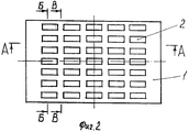
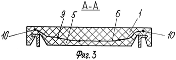
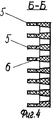
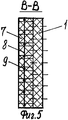
На фиг.1 изображен вид сита сбоку; на фиг.2 - вид сверху; на фиг.3 показан разрез по А-А фиг.2, на фиг.4 изображен разрез по Б-Б фиг.2, а на фиг.5 - разрез по В-В фиг.2.Figure 1 shows a side view of a sieve; figure 2 is a top view; figure 3 shows a section along aa of figure 2, figure 4 shows a section along bb of figure 2, and figure 5 is a section along bb of figure 2.
Сито грохота состоит из эластичной основы 1 с отверстиями 2. Эластичная основа имеет опорные выступы 3, которыми сито установлено в продольных опорах 4 грохота. Снизу эластичной основы выполнены поперечные ребра 5, расположенные между отверстиями. В эти ребра заформованы армирующие нитки 6. Дополнительно снизу эластичной основы между отверстиями выполнены продольные ребра 7, при этом в них заформованы дополнительные армирующие нитки 8, которые в местах пересечения ребер соединены узлами 9 с армирующими нитками поперечных ребер. Концы 10 армирующих ниток у концов ребер заведены в эластичную основу 1.The sieve of the screen consists of an
В процессе работы грохота перемещение ситу передается от продольных опор 4 грохота через опорные выступы 3. Грохотимый материал попадает на эластичную основу 1, перемещается по ней и его мелкая фракция просеивается в подрешетное пространство через отверстия 2. При этом ребра 5 и 7 вместе с армирующими нитками 6 и 8 обеспечивают повышенную жесткость сита при использовании резины с низкой и средней твердостью, которая выбрана по условиям минимального износа. При этом узлы 9, которыми связаны армирующие нитки 6 и 8, а также концы 10 армирующих ниток, заведенные в эластичную основу 1, способствуют еще большему повышению жесткости сита и создают условия, при которых невозможно отслоение армирующих ниток сита. Все это повышает надежность работы сита.During the operation of the screen, the movement of the sieve is transmitted from the longitudinal supports 4 of the screen through the
Claims (1)
Applications Claiming Priority (2)
| Application Number | Priority Date | Filing Date | Title |
|---|---|---|---|
| UA20031110129A UA68848A (en) | 2003-11-11 | 2003-11-11 | Screen sieve |
| UA20031110129 | 2003-11-11 |
Publications (2)
| Publication Number | Publication Date |
|---|---|
| RU2004127140A RU2004127140A (en) | 2006-02-20 |
| RU2296630C2 true RU2296630C2 (en) | 2007-04-10 |
Family
ID=34511973
Family Applications (1)
| Application Number | Title | Priority Date | Filing Date |
|---|---|---|---|
| RU2004127140/03A RU2296630C2 (en) | 2003-11-11 | 2004-09-09 | Jigging sieve |
Country Status (2)
| Country | Link |
|---|---|
| RU (1) | RU2296630C2 (en) |
| UA (1) | UA68848A (en) |
Cited By (8)
| Publication number | Priority date | Publication date | Assignee | Title |
|---|---|---|---|---|
| RU2543393C2 (en) * | 2010-04-19 | 2015-02-27 | Деррик Корпорейшн | Polyurethane vibrating screen |
| US10960438B2 (en) | 2012-05-25 | 2021-03-30 | Derrick Corporation | Injection molded screening apparatuses and methods |
| USD915484S1 (en) | 2017-06-06 | 2021-04-06 | Derrick Corporation | Interstage screen basket |
| US11161150B2 (en) | 2012-05-25 | 2021-11-02 | Derrick Corporation | Injection molded screening apparatuses and methods |
| US11203678B2 (en) | 2017-04-28 | 2021-12-21 | Derrick Corporation | Thermoplastic compositions, methods, apparatus, and uses |
| US11213857B2 (en) | 2017-06-06 | 2022-01-04 | Derrick Corporation | Method and apparatus for screening |
| US11458505B2 (en) | 2017-09-01 | 2022-10-04 | Derrick Corporation | Deblinding apparatuses and methods for screening |
| US11505638B2 (en) | 2017-04-28 | 2022-11-22 | Derrick Corporation | Thermoplastic compositions, methods, apparatus, and uses |
-
2003
- 2003-11-11 UA UA20031110129A patent/UA68848A/en unknown
-
2004
- 2004-09-09 RU RU2004127140/03A patent/RU2296630C2/en not_active IP Right Cessation
Non-Patent Citations (1)
| Title |
|---|
| НАДУТЫЙ В.П. и др., Полимерные просеивающие поверхности виброгрохотов, Москва, "Недра", 1993, с.15-17, 66-72, 86. * |
Cited By (15)
| Publication number | Priority date | Publication date | Assignee | Title |
|---|---|---|---|---|
| RU2543393C2 (en) * | 2010-04-19 | 2015-02-27 | Деррик Корпорейшн | Polyurethane vibrating screen |
| RU2766874C2 (en) * | 2010-04-19 | 2022-03-16 | Деррик Корпорейшн | Polyurethane vibration sieve |
| US11000882B2 (en) | 2012-05-25 | 2021-05-11 | Derrick Corporation | Injection molded screening apparatuses and methods |
| US10974281B2 (en) | 2012-05-25 | 2021-04-13 | Derrick Corporation | Injection molded screening apparatuses and methods |
| US10981197B2 (en) | 2012-05-25 | 2021-04-20 | Derrick Corporation | Injection molded screening apparatuses and methods |
| US10994306B2 (en) | 2012-05-25 | 2021-05-04 | Derrick Corporation | Injection molded screening apparatuses and methods |
| US11161150B2 (en) | 2012-05-25 | 2021-11-02 | Derrick Corporation | Injection molded screening apparatuses and methods |
| US10960438B2 (en) | 2012-05-25 | 2021-03-30 | Derrick Corporation | Injection molded screening apparatuses and methods |
| US11203678B2 (en) | 2017-04-28 | 2021-12-21 | Derrick Corporation | Thermoplastic compositions, methods, apparatus, and uses |
| US11505638B2 (en) | 2017-04-28 | 2022-11-22 | Derrick Corporation | Thermoplastic compositions, methods, apparatus, and uses |
| USD915484S1 (en) | 2017-06-06 | 2021-04-06 | Derrick Corporation | Interstage screen basket |
| US11213857B2 (en) | 2017-06-06 | 2022-01-04 | Derrick Corporation | Method and apparatus for screening |
| US11213856B2 (en) | 2017-06-06 | 2022-01-04 | Derrick Corporation | Method and apparatuses for screening |
| US11247236B2 (en) | 2017-06-06 | 2022-02-15 | Derrick Corporation | Method and apparatuses for screening |
| US11458505B2 (en) | 2017-09-01 | 2022-10-04 | Derrick Corporation | Deblinding apparatuses and methods for screening |
Also Published As
| Publication number | Publication date |
|---|---|
| RU2004127140A (en) | 2006-02-20 |
| UA68848A (en) | 2004-08-16 |
Similar Documents
| Publication | Publication Date | Title |
|---|---|---|
| US4380494A (en) | Vibrating screen with self-supporting screen cloth | |
| TWI656918B (en) | Method and apparatuses for pre-screening | |
| US4288320A (en) | Vibrating screen with screen deck unclogging mechanism | |
| DE60004184D1 (en) | SCREEN CONSTRUCTION, VIBRATION SEPARATOR AND METHOD FOR SCREENING | |
| RU2296630C2 (en) | Jigging sieve | |
| DE69940736D1 (en) | FLAT SCREEN FOR KRONBODENRÜTTLER | |
| RU2008123788A (en) | SIEVING DEVICE | |
| AU2001294053A1 (en) | A screen for a shale shaker | |
| CN202238633U (en) | Immersed sieving machine | |
| US6825136B2 (en) | Filtering screens for vibratory separation equipment | |
| CN102089087A (en) | Improved sifting screen | |
| ATE232759T1 (en) | SORTING WASTE MATERIAL | |
| US6685028B1 (en) | Screening equipment | |
| RU2018140790A (en) | VIBRATOR SCREENER | |
| CN108499853A (en) | A kind of material combinations testing sifter | |
| CN207735229U (en) | Noble metal catalyst prepares the suspension sieve-plate structure vibrating screen of material | |
| US4696738A (en) | Material separating surface | |
| GB2073618A (en) | Vibratory screening panels | |
| JPH09234425A (en) | Screen clogging prevention device for vibrating screen classifier | |
| SU1554991A1 (en) | Screen | |
| SU1706723A1 (en) | Sieve | |
| SU1695999A1 (en) | Vibration screen | |
| SU1102637A1 (en) | Vibration-screening device for suspensions | |
| US962618A (en) | Jig. | |
| SU1251965A1 (en) | Screen |
Legal Events
| Date | Code | Title | Description |
|---|---|---|---|
| MM4A | The patent is invalid due to non-payment of fees |
Effective date: 20070910 |