US11408564B2 - Self-sealing valve connection for pressure vessels - Google Patents
Self-sealing valve connection for pressure vessels Download PDFInfo
- Publication number
- US11408564B2 US11408564B2 US17/254,626 US201917254626A US11408564B2 US 11408564 B2 US11408564 B2 US 11408564B2 US 201917254626 A US201917254626 A US 201917254626A US 11408564 B2 US11408564 B2 US 11408564B2
- Authority
- US
- United States
- Prior art keywords
- protrusion
- sleeve
- vessel
- sealing
- face
- Prior art date
- Legal status (The legal status is an assumption and is not a legal conclusion. Google has not performed a legal analysis and makes no representation as to the accuracy of the status listed.)
- Active, expires
Links
Images


Classifications
-
- F—MECHANICAL ENGINEERING; LIGHTING; HEATING; WEAPONS; BLASTING
- F17—STORING OR DISTRIBUTING GASES OR LIQUIDS
- F17C—VESSELS FOR CONTAINING OR STORING COMPRESSED, LIQUEFIED OR SOLIDIFIED GASES; FIXED-CAPACITY GAS-HOLDERS; FILLING VESSELS WITH, OR DISCHARGING FROM VESSELS, COMPRESSED, LIQUEFIED, OR SOLIDIFIED GASES
- F17C13/00—Details of vessels or of the filling or discharging of vessels
- F17C13/04—Arrangement or mounting of valves
-
- F—MECHANICAL ENGINEERING; LIGHTING; HEATING; WEAPONS; BLASTING
- F17—STORING OR DISTRIBUTING GASES OR LIQUIDS
- F17C—VESSELS FOR CONTAINING OR STORING COMPRESSED, LIQUEFIED OR SOLIDIFIED GASES; FIXED-CAPACITY GAS-HOLDERS; FILLING VESSELS WITH, OR DISCHARGING FROM VESSELS, COMPRESSED, LIQUEFIED, OR SOLIDIFIED GASES
- F17C1/00—Pressure vessels, e.g. gas cylinder, gas tank, replaceable cartridge
- F17C1/02—Pressure vessels, e.g. gas cylinder, gas tank, replaceable cartridge involving reinforcing arrangements
- F17C1/04—Protecting sheathings
- F17C1/06—Protecting sheathings built-up from wound-on bands or filamentary material, e.g. wires
-
- F—MECHANICAL ENGINEERING; LIGHTING; HEATING; WEAPONS; BLASTING
- F17—STORING OR DISTRIBUTING GASES OR LIQUIDS
- F17C—VESSELS FOR CONTAINING OR STORING COMPRESSED, LIQUEFIED OR SOLIDIFIED GASES; FIXED-CAPACITY GAS-HOLDERS; FILLING VESSELS WITH, OR DISCHARGING FROM VESSELS, COMPRESSED, LIQUEFIED, OR SOLIDIFIED GASES
- F17C1/00—Pressure vessels, e.g. gas cylinder, gas tank, replaceable cartridge
- F17C1/16—Pressure vessels, e.g. gas cylinder, gas tank, replaceable cartridge constructed of plastics materials
-
- F—MECHANICAL ENGINEERING; LIGHTING; HEATING; WEAPONS; BLASTING
- F17—STORING OR DISTRIBUTING GASES OR LIQUIDS
- F17C—VESSELS FOR CONTAINING OR STORING COMPRESSED, LIQUEFIED OR SOLIDIFIED GASES; FIXED-CAPACITY GAS-HOLDERS; FILLING VESSELS WITH, OR DISCHARGING FROM VESSELS, COMPRESSED, LIQUEFIED, OR SOLIDIFIED GASES
- F17C2201/00—Vessel construction, in particular geometry, arrangement or size
- F17C2201/01—Shape
- F17C2201/0104—Shape cylindrical
- F17C2201/0109—Shape cylindrical with exteriorly curved end-piece
-
- F—MECHANICAL ENGINEERING; LIGHTING; HEATING; WEAPONS; BLASTING
- F17—STORING OR DISTRIBUTING GASES OR LIQUIDS
- F17C—VESSELS FOR CONTAINING OR STORING COMPRESSED, LIQUEFIED OR SOLIDIFIED GASES; FIXED-CAPACITY GAS-HOLDERS; FILLING VESSELS WITH, OR DISCHARGING FROM VESSELS, COMPRESSED, LIQUEFIED, OR SOLIDIFIED GASES
- F17C2201/00—Vessel construction, in particular geometry, arrangement or size
- F17C2201/05—Size
- F17C2201/054—Size medium (>1 m3)
-
- F—MECHANICAL ENGINEERING; LIGHTING; HEATING; WEAPONS; BLASTING
- F17—STORING OR DISTRIBUTING GASES OR LIQUIDS
- F17C—VESSELS FOR CONTAINING OR STORING COMPRESSED, LIQUEFIED OR SOLIDIFIED GASES; FIXED-CAPACITY GAS-HOLDERS; FILLING VESSELS WITH, OR DISCHARGING FROM VESSELS, COMPRESSED, LIQUEFIED, OR SOLIDIFIED GASES
- F17C2201/00—Vessel construction, in particular geometry, arrangement or size
- F17C2201/05—Size
- F17C2201/056—Small (<1 m3)
-
- F—MECHANICAL ENGINEERING; LIGHTING; HEATING; WEAPONS; BLASTING
- F17—STORING OR DISTRIBUTING GASES OR LIQUIDS
- F17C—VESSELS FOR CONTAINING OR STORING COMPRESSED, LIQUEFIED OR SOLIDIFIED GASES; FIXED-CAPACITY GAS-HOLDERS; FILLING VESSELS WITH, OR DISCHARGING FROM VESSELS, COMPRESSED, LIQUEFIED, OR SOLIDIFIED GASES
- F17C2203/00—Vessel construction, in particular walls or details thereof
- F17C2203/01—Reinforcing or suspension means
- F17C2203/011—Reinforcing means
-
- F—MECHANICAL ENGINEERING; LIGHTING; HEATING; WEAPONS; BLASTING
- F17—STORING OR DISTRIBUTING GASES OR LIQUIDS
- F17C—VESSELS FOR CONTAINING OR STORING COMPRESSED, LIQUEFIED OR SOLIDIFIED GASES; FIXED-CAPACITY GAS-HOLDERS; FILLING VESSELS WITH, OR DISCHARGING FROM VESSELS, COMPRESSED, LIQUEFIED, OR SOLIDIFIED GASES
- F17C2203/00—Vessel construction, in particular walls or details thereof
- F17C2203/06—Materials for walls or layers thereof; Properties or structures of walls or their materials
- F17C2203/0602—Wall structures; Special features thereof
- F17C2203/0604—Liners
-
- F—MECHANICAL ENGINEERING; LIGHTING; HEATING; WEAPONS; BLASTING
- F17—STORING OR DISTRIBUTING GASES OR LIQUIDS
- F17C—VESSELS FOR CONTAINING OR STORING COMPRESSED, LIQUEFIED OR SOLIDIFIED GASES; FIXED-CAPACITY GAS-HOLDERS; FILLING VESSELS WITH, OR DISCHARGING FROM VESSELS, COMPRESSED, LIQUEFIED, OR SOLIDIFIED GASES
- F17C2203/00—Vessel construction, in particular walls or details thereof
- F17C2203/06—Materials for walls or layers thereof; Properties or structures of walls or their materials
- F17C2203/0602—Wall structures; Special features thereof
- F17C2203/0612—Wall structures
- F17C2203/0614—Single wall
- F17C2203/0619—Single wall with two layers
-
- F—MECHANICAL ENGINEERING; LIGHTING; HEATING; WEAPONS; BLASTING
- F17—STORING OR DISTRIBUTING GASES OR LIQUIDS
- F17C—VESSELS FOR CONTAINING OR STORING COMPRESSED, LIQUEFIED OR SOLIDIFIED GASES; FIXED-CAPACITY GAS-HOLDERS; FILLING VESSELS WITH, OR DISCHARGING FROM VESSELS, COMPRESSED, LIQUEFIED, OR SOLIDIFIED GASES
- F17C2203/00—Vessel construction, in particular walls or details thereof
- F17C2203/06—Materials for walls or layers thereof; Properties or structures of walls or their materials
- F17C2203/0634—Materials for walls or layers thereof
- F17C2203/0658—Synthetics
- F17C2203/066—Plastics
-
- F—MECHANICAL ENGINEERING; LIGHTING; HEATING; WEAPONS; BLASTING
- F17—STORING OR DISTRIBUTING GASES OR LIQUIDS
- F17C—VESSELS FOR CONTAINING OR STORING COMPRESSED, LIQUEFIED OR SOLIDIFIED GASES; FIXED-CAPACITY GAS-HOLDERS; FILLING VESSELS WITH, OR DISCHARGING FROM VESSELS, COMPRESSED, LIQUEFIED, OR SOLIDIFIED GASES
- F17C2203/00—Vessel construction, in particular walls or details thereof
- F17C2203/06—Materials for walls or layers thereof; Properties or structures of walls or their materials
- F17C2203/0634—Materials for walls or layers thereof
- F17C2203/0658—Synthetics
- F17C2203/0663—Synthetics in form of fibers or filaments
-
- F—MECHANICAL ENGINEERING; LIGHTING; HEATING; WEAPONS; BLASTING
- F17—STORING OR DISTRIBUTING GASES OR LIQUIDS
- F17C—VESSELS FOR CONTAINING OR STORING COMPRESSED, LIQUEFIED OR SOLIDIFIED GASES; FIXED-CAPACITY GAS-HOLDERS; FILLING VESSELS WITH, OR DISCHARGING FROM VESSELS, COMPRESSED, LIQUEFIED, OR SOLIDIFIED GASES
- F17C2203/00—Vessel construction, in particular walls or details thereof
- F17C2203/06—Materials for walls or layers thereof; Properties or structures of walls or their materials
- F17C2203/068—Special properties of materials for vessel walls
- F17C2203/0685—Special properties of materials for vessel walls flexible
-
- F—MECHANICAL ENGINEERING; LIGHTING; HEATING; WEAPONS; BLASTING
- F17—STORING OR DISTRIBUTING GASES OR LIQUIDS
- F17C—VESSELS FOR CONTAINING OR STORING COMPRESSED, LIQUEFIED OR SOLIDIFIED GASES; FIXED-CAPACITY GAS-HOLDERS; FILLING VESSELS WITH, OR DISCHARGING FROM VESSELS, COMPRESSED, LIQUEFIED, OR SOLIDIFIED GASES
- F17C2205/00—Vessel construction, in particular mounting arrangements, attachments or identifications means
- F17C2205/03—Fluid connections, filters, valves, closure means or other attachments
- F17C2205/0302—Fittings, valves, filters, or components in connection with the gas storage device
- F17C2205/0305—Bosses, e.g. boss collars
-
- F—MECHANICAL ENGINEERING; LIGHTING; HEATING; WEAPONS; BLASTING
- F17—STORING OR DISTRIBUTING GASES OR LIQUIDS
- F17C—VESSELS FOR CONTAINING OR STORING COMPRESSED, LIQUEFIED OR SOLIDIFIED GASES; FIXED-CAPACITY GAS-HOLDERS; FILLING VESSELS WITH, OR DISCHARGING FROM VESSELS, COMPRESSED, LIQUEFIED, OR SOLIDIFIED GASES
- F17C2205/00—Vessel construction, in particular mounting arrangements, attachments or identifications means
- F17C2205/03—Fluid connections, filters, valves, closure means or other attachments
- F17C2205/0302—Fittings, valves, filters, or components in connection with the gas storage device
- F17C2205/0323—Valves
-
- F—MECHANICAL ENGINEERING; LIGHTING; HEATING; WEAPONS; BLASTING
- F17—STORING OR DISTRIBUTING GASES OR LIQUIDS
- F17C—VESSELS FOR CONTAINING OR STORING COMPRESSED, LIQUEFIED OR SOLIDIFIED GASES; FIXED-CAPACITY GAS-HOLDERS; FILLING VESSELS WITH, OR DISCHARGING FROM VESSELS, COMPRESSED, LIQUEFIED, OR SOLIDIFIED GASES
- F17C2205/00—Vessel construction, in particular mounting arrangements, attachments or identifications means
- F17C2205/03—Fluid connections, filters, valves, closure means or other attachments
- F17C2205/0388—Arrangement of valves, regulators, filters
- F17C2205/0394—Arrangement of valves, regulators, filters in direct contact with the pressure vessel
-
- F—MECHANICAL ENGINEERING; LIGHTING; HEATING; WEAPONS; BLASTING
- F17—STORING OR DISTRIBUTING GASES OR LIQUIDS
- F17C—VESSELS FOR CONTAINING OR STORING COMPRESSED, LIQUEFIED OR SOLIDIFIED GASES; FIXED-CAPACITY GAS-HOLDERS; FILLING VESSELS WITH, OR DISCHARGING FROM VESSELS, COMPRESSED, LIQUEFIED, OR SOLIDIFIED GASES
- F17C2209/00—Vessel construction, in particular methods of manufacturing
- F17C2209/21—Shaping processes
- F17C2209/2109—Moulding
- F17C2209/2118—Moulding by injection
-
- F—MECHANICAL ENGINEERING; LIGHTING; HEATING; WEAPONS; BLASTING
- F17—STORING OR DISTRIBUTING GASES OR LIQUIDS
- F17C—VESSELS FOR CONTAINING OR STORING COMPRESSED, LIQUEFIED OR SOLIDIFIED GASES; FIXED-CAPACITY GAS-HOLDERS; FILLING VESSELS WITH, OR DISCHARGING FROM VESSELS, COMPRESSED, LIQUEFIED, OR SOLIDIFIED GASES
- F17C2221/00—Handled fluid, in particular type of fluid
- F17C2221/01—Pure fluids
- F17C2221/012—Hydrogen
-
- F—MECHANICAL ENGINEERING; LIGHTING; HEATING; WEAPONS; BLASTING
- F17—STORING OR DISTRIBUTING GASES OR LIQUIDS
- F17C—VESSELS FOR CONTAINING OR STORING COMPRESSED, LIQUEFIED OR SOLIDIFIED GASES; FIXED-CAPACITY GAS-HOLDERS; FILLING VESSELS WITH, OR DISCHARGING FROM VESSELS, COMPRESSED, LIQUEFIED, OR SOLIDIFIED GASES
- F17C2223/00—Handled fluid before transfer, i.e. state of fluid when stored in the vessel or before transfer from the vessel
- F17C2223/01—Handled fluid before transfer, i.e. state of fluid when stored in the vessel or before transfer from the vessel characterised by the phase
- F17C2223/0107—Single phase
- F17C2223/0123—Single phase gaseous, e.g. CNG, GNC
-
- F—MECHANICAL ENGINEERING; LIGHTING; HEATING; WEAPONS; BLASTING
- F17—STORING OR DISTRIBUTING GASES OR LIQUIDS
- F17C—VESSELS FOR CONTAINING OR STORING COMPRESSED, LIQUEFIED OR SOLIDIFIED GASES; FIXED-CAPACITY GAS-HOLDERS; FILLING VESSELS WITH, OR DISCHARGING FROM VESSELS, COMPRESSED, LIQUEFIED, OR SOLIDIFIED GASES
- F17C2223/00—Handled fluid before transfer, i.e. state of fluid when stored in the vessel or before transfer from the vessel
- F17C2223/03—Handled fluid before transfer, i.e. state of fluid when stored in the vessel or before transfer from the vessel characterised by the pressure level
- F17C2223/036—Very high pressure (>80 bar)
-
- F—MECHANICAL ENGINEERING; LIGHTING; HEATING; WEAPONS; BLASTING
- F17—STORING OR DISTRIBUTING GASES OR LIQUIDS
- F17C—VESSELS FOR CONTAINING OR STORING COMPRESSED, LIQUEFIED OR SOLIDIFIED GASES; FIXED-CAPACITY GAS-HOLDERS; FILLING VESSELS WITH, OR DISCHARGING FROM VESSELS, COMPRESSED, LIQUEFIED, OR SOLIDIFIED GASES
- F17C2260/00—Purposes of gas storage and gas handling
- F17C2260/03—Dealing with losses
- F17C2260/035—Dealing with losses of fluid
- F17C2260/036—Avoiding leaks
-
- F—MECHANICAL ENGINEERING; LIGHTING; HEATING; WEAPONS; BLASTING
- F17—STORING OR DISTRIBUTING GASES OR LIQUIDS
- F17C—VESSELS FOR CONTAINING OR STORING COMPRESSED, LIQUEFIED OR SOLIDIFIED GASES; FIXED-CAPACITY GAS-HOLDERS; FILLING VESSELS WITH, OR DISCHARGING FROM VESSELS, COMPRESSED, LIQUEFIED, OR SOLIDIFIED GASES
- F17C2270/00—Applications
- F17C2270/01—Applications for fluid transport or storage
- F17C2270/0165—Applications for fluid transport or storage on the road
- F17C2270/0168—Applications for fluid transport or storage on the road by vehicles
-
- Y—GENERAL TAGGING OF NEW TECHNOLOGICAL DEVELOPMENTS; GENERAL TAGGING OF CROSS-SECTIONAL TECHNOLOGIES SPANNING OVER SEVERAL SECTIONS OF THE IPC; TECHNICAL SUBJECTS COVERED BY FORMER USPC CROSS-REFERENCE ART COLLECTIONS [XRACs] AND DIGESTS
- Y02—TECHNOLOGIES OR APPLICATIONS FOR MITIGATION OR ADAPTATION AGAINST CLIMATE CHANGE
- Y02E—REDUCTION OF GREENHOUSE GAS [GHG] EMISSIONS, RELATED TO ENERGY GENERATION, TRANSMISSION OR DISTRIBUTION
- Y02E60/00—Enabling technologies; Technologies with a potential or indirect contribution to GHG emissions mitigation
- Y02E60/30—Hydrogen technology
- Y02E60/32—Hydrogen storage
Definitions
- the invention relates to a pressure vessel with a self-sealing valve-connection piece and a method of producing such a pressure vessel.
- the pressure vessels must be reliably sealed, for a filling gas stored at high pressure in the pressure vessel over a large temperature range and a long period of time, under alternating load conditions (evacuation of the pressure vessel, refilling of the vessel and so on), in accordance with the standard and/or customer requirements.
- gas-tightness is aimed at by means of O ring seals. There is no redundancy for the place to be sealed, which may easily lead to failure of the seal if the fitting conditions of the O ring in relation to the other components change.
- valve connection for pressure vessels which is self-sealing and guarantees permanent and reliable sealing of the valve connection with respect to the inner vessel.
- a pressure vessel comprising an inner vessel that has an inner and an outer face and is made of an inner-vessel material that is at least partially plastically deformable under pressure for providing a storage volume in the pressure vessel, an outer layer applied on the inner vessel for the reinforcement thereof, and a valve-connection piece arranged on the inner vessel having a two-part, hollow sealing cone and an outer piece for receiving a valve and for sealing the storage volume from the inner vessel, the inner vessel comprising, for connecting the valve-connection piece, a protrusion that is inwardly open towards the storage volume and projects cylindrically from the outer face, the two-part sealing cone being positioned on an inner face of the protrusion and the outer piece for generating a sealing pressure between the two-part sealing cone, the protrusion and the outer piece on an outer face of the protrusion, the outer piece comprising, on the face thereof oriented towards the protrusion, a suitably shaped groove having a first edge facing the storage volume and a second edge provided in the opposite direction for receiving a sealing ring
- the inner vessel can be made of one piece or of multiple pieces. It can comprise merely two pole caps, one or two of which may comprise a cylindrical edge portion. If the inner vessel consists of multiple pieces, the edges of the pole caps are caused to be in direct contact and suitably interconnected. Alternatively, the inner vessel can also comprise, in addition to the pole caps, a cylindrical central portion which is preferably made of the same material as the pole caps.
- a cylinder axis of the inner vessel, or the pressure vessel, respectively, corresponds to the axis of symmetry of any cylindrical portion of the inner vessel, if present, or, if the inner vessel is only formed by two pole caps, the axis between the central points of the respective pole caps which also correspond to the highest points of the respective domes formed by the pole caps.
- the plastically deformable inner-vessel material is, on the one hand, firm and stable in itself, but also has a certain fluidity so that at least its surface can plastically deform under high pressure and is therefore able to adapt to the contour of the pressing surfaces, but without the forming of large deformations.
- the inner vessel also has the function of providing a gas-tight storage volume for storing filling gas in the pressure vessel, so that the inner-vessel material should be gas-tight and should be, for instance, metal or plastic, in case of plastic, preferably PA or PE, as an individual layer or a multi-layer system.
- the filling gas can be any gas, for example hydrogen.
- the outer layer provides the pressure vessel with mechanical stability; that is, the outer layer provides the functionality of compression strength and the inner vessel of impermeability to gas.
- the outer layer can be, for instance, a fibre composite layer wound onto the inner vessel or applied on it by other techniques.
- the sealing ring positioned in the groove does not completely fill the groove in the outer piece but leaves gaps in the groove on both sides towards the interior of the outer piece; a first and a second gap which are used to provide redundancy of the sealing effect.
- This sealing concept provides a triple redundancy for sealing the storage volume by means of triple sealing ensured serially by the (i) first sealing bead of the protrusion, acting against the outer piece, (ii) sealing cone, acting via protrusion on the sealing ring, and (iii) second sealing bead of the protrusion, acting against the outer piece, thus greatly improving on reliability and permanence of the sealing. Due to the formation of the sealing beads, caused by the sealing pressure exerted by the valve-connection piece, the valve-connection piece is additionally self-sealing.
- the sealing concept is independent of the material of the two-part sealing cone and of the connection piece; although the materials forming the two-part sealing cone and the connection piece have at least a lower fluidity than the inner-vessel material.
- the clamping cone is held by means of a positioning aid, for instance a rod with a strutting end, below the clamping cone in the storage volume or with a thread inside the clamping cone, and then the sleeve is inserted into the protrusion from the outside.
- a positioning aid for instance a rod with a strutting end
- the clamping cone is drawn into the sleeve from the inside by means of the positioning aid, sleeve and protrusion being slightly stretched so that the inner face of the sleeve and the outer face of the clamping cone form a tight fit.
- the positioning aid can be omitted since the protrusion is freely accessible from the inside and therefore the clamping cone can be simply slid from there into the sleeve.
- “Locally convex” and “locally concave”, respectively, are terms to designate convexities or concavities, respectively, which may extend over the entire inner face of the sleeve or the outer face of the clamping cone but may also designate local convexities or concavities of parts of the respective faces.
- Outer piece, sleeve and clamping cone can consist of any material suitable for this purpose, for instance, metal or plastic.
- the specified pressure vessel has a very flexible construction such that customer-specific valve-connection pieces are easy to adapt by respective shaping of the protrusion and the two-part sealing cone.
- a supplementary sleeve can be integrated for the integration of sensor systems, sensors or other components extending into the pressure vessel.
- the pressure vessel according to the invention therefore is a pressure vessel with a valve connection which is self-sealing and ensures permanent and reliable sealing of the valve connection with respect to the inner vessel.
- the inner vessel is produced in one piece.
- the sealing concept described above can be very well applied to one-part inner vessels, since the final sealing means, the inner clamping cone, is dimensioned such as to fit through the opening to be sealed and can therefore be brought into the necessary position with the aid of a suitable positioning aid without requiring access to the inner vessel from the rear or the inside in addition to the necessary opening for filling and evacuation of the pressure vessel, which is already there, through the protrusion.
- the sleeve is formed such that it comprises a stop facing an upper face of the protrusion and/or at least partially rests on an inner face of the outer piece extending at least over the sleeve and the protrusion. In this manner, the sleeve cannot slide into the storage volume and/or slide out of the opening of the protrusion along its inner face, for instance if the clamping cone is positioned from the inside.
- the sleeve is dimensioned such that the inner-vessel material forms, due to its plastic deformability, a third bead around the sleeve on its lower face directed towards the storage volume. This prevents displacement of the sleeve in the direction of the storage volume.
- the sealing pressure on the sealing ring is maintained as originally set. Also, the sleeve and the clamping cone anchored to it according to the invention cannot slide or fall into the storage volume in case of concussion of the pressure vessel.
- the two-part sealing cone or the outer piece are formed such that there is an open gas connection towards the storage volume between the storage volume and an upper face of the protrusion.
- the gas connection can be provided, for instance, by means of suitable channels, recesses or grooves in the sleeve and/or the clamping cone.
- the sleeve comprises an outer face facing the protrusion, the surface area of the outer face of the sleeve resting on the protrusion and/or the outer face of the clamping cone resting on the sleeve being smaller than those of the respective inner faces. Due to the different area ratios of the inner face and the outer face, with a gas connection between the storage volume and the upper face of the protrusion, the sealing pressure is additionally increased by the interior pressure in the storage volume of the pressure vessel, and, in case of a pressure rise in the storage volume (for instance during filling of the storage volume with gas, e. g. up to 500 bar), the sealing cone is additionally pressed in the direction of the outer piece, further improving the sealing effect and its reliability.
- the groove (or recess) has a contour which is adapted to a shape of the sealing ring in the unloaded state. In this way, no undefined hollow spaces can form behind the sealing ring, further improving the sealing effect of the sealing ring.
- the sealing ring is an O ring.
- O rings have, on the one hand, reliable sealing properties, and on the other hand, it is also easiest for them to form suitable contours in the groove.
- the curvature of the groove is adapted to the curvature of the surface of the O ring.
- the sealing ring that is, in this case, the O ring, can consist of all materials suitable for gas sealing.
- the inner vessel material is a PA material, a PE material or a multi-layered material made of these materials. These materials have suitable properties for manufacturing the inner vessel and additionally provide suitable fluidity for forming the sealing beads, ensuring the additional sealing effect together with secure positioning of the components of the connection piece in the pressure vessel.
- the inner vessel can also consist entirely of these materials. The above materials are also suitable for being welded together for manufacturing from the components pole caps and, if desired, a central portion of an inner vessel for providing the storage volume.
- valve-connection piece comprises an additional securing element which interconnects the two-part sealing cone and the outer piece. This helps to prevent displacement of the two-part sealing cone, i. e. of the sleeve and the clamping cone, in relation to the outer piece, in particular in the direction of the outer piece.
- the securing element is mounted in the outer piece and comprises a thread, at least on its side facing the sealing cone, which thread is provided for engagement in the inner face of the sealing cone.
- the securing element can be, for instance, a hollow screw or an accordingly shaped ring with through openings for exerting pressure on the upper face of the protrusion of the inner vessel.
- the outer piece of the valve-connection piece comprises connection means for receiving the valve in a pressure-stable manner.
- a valve can be screwed in a pressure-stable manner into a corresponding thread as a connecting means of the outer piece.
- the invention furthermore relates to a method for producing a pressure vessel according to the invention, comprising an inner vessel that has an inner and an outer face and is made of an inner-vessel material that is at least partially plastically deformable under pressure, designed for receiving a valve, an outer layer positioned on the inner vessel and a valve-connection piece having a two-part sealing cone consisting of a hollow outer sleeve and a hollow inner clamping cone as well as an outer piece, comprising the following steps:
- the inner vessel with a storage volume and a protrusion that is inwardly open and projects cylindrically from the outer face of the inner vessel; positioning the clamping cone having a largest external diameter that is smaller than an internal diameter of the protrusion and a largest external diameter that is larger than the smallest internal diameter of the sleeve towards the protrusion by means of a positioning aid, through the protrusion, in the storage volume of the inner vessel; inserting the hollow sleeve of the sealing cone from outside into a tight fit on the inner face of the protrusion, the sleeve having a smallest internal diameter and an external diameter adapted to the protrusion, while the positioning aid and the clamping cone are not influenced thereby; fitting the outer piece onto the outer face of the protrusion, the outer piece comprising, on its face oriented towards the protrusion, a suitably shaped groove having a first edge facing the future storage volume and a second edge provided in the opposite direction, and a sealing ring that is positioned in the groove and seals under
- the method according to the invention thus provides a pressure vessel with a valve connection which is self-sealing and ensures permanent and reliable sealing of the valve connection with respect to the inner vessel.
- the method comprises the additional step of forming a third bead around the sealing cone on its lower face directed towards the storage volume due to the plastic deformability of the inner-vessel material.
- the outer layer consists of fibre composite material and is wound onto the inner vessel in the producing step. Since the inner vessel itself forms the winding mandrel for the outer layer, the outer layer is formed so as to accurately fit the respective inner vessel.
- the valve is fitted by being screwed on.
- the outer piece can already have an accordingly provided thread, or the valve has a thread that cuts itself into the outer piece.
- the sleeve is inserted onto an upper face of the protrusion up to a stop of the sleeve and/or the outer piece is fitted to the sleeve and/or to the clamping cone until it comes in contact with an inner face of the outer piece.
- sleeve and/or clamping cone are fixed in position by the outer piece such that they cannot slide to the outside along the inner face of the protrusion, which might change the sealing pressure and consequently the sealing effect.
- the inner vessel is produced in one piece, for example as a blow-molded part or by injection molding.
- the production in one piece avoids additional process steps such as the joining of pole caps and of a central portion, if applicable.
- the production in one piece also avoids joining errors in the transition from a pole cap to the central portion, which might be the cause of gas leakage.
- the inner vessel is also mechanically more robust than an inner vessel where several components are joined.
- FIG. 1 an embodiment of the pressure vessel according to the invention in lateral section;
- FIG. 2 the pressure vessel of FIG. 1 shown in an enlarged sectional view of the valve-connection piece and the protrusion of the inner vessel;
- FIG. 3 schematic presentation of the sealing concept according to the invention with outer piece, protrusion of the inner vessel, two-part sealing cone and the formed sealing beads;
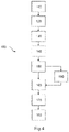
- FIG. 4 an embodiment of the method according to the invention for producing the pressure vessel according to the invention.
- FIG. 1 shows an embodiment of the pressure vessel 1 according to the invention in lateral section, comprising a one-part inner vessel 2 that has an inner and an outer face 2 i , 2 a and is made of an inner-vessel material that is at least partially plastically deformable under pressure, here having a cylindrical central portion 21 with a cylinder axis ZA and two pole caps 22 bordering on the cylindrical central portion 21 for providing a storage volume SV in the pressure vessel.
- a cylindrical central portion 21 with a cylinder axis ZA and two pole caps 22 bordering on the cylindrical central portion 21 for providing a storage volume SV in the pressure vessel.
- the opposite pole cap 22 which is not shown here, for closing the central portion 21 on the other side, may not comprise a protrusion 23 but instead a continuous closed contour or corresponds to the pole cap 22 as shown with its own sealable opening or a corresponding valve-connection piece.
- the inner vessel 2 may only consist of the two pole caps 22 , without the cylindrical central portion 21 shown here.
- all embodiments of the invention as shown in FIGS. 1-4 apply analogously.
- the inner-vessel material can be any plastically deformable material.
- the inner-vessel material is a PA, PE or multi-layered material made of the former, at least for the protrusion 23 .
- An outer layer 3 is applied on the inner vessel 2 for reinforcement.
- a valve-connection piece 4 with a two-part sealing cone 41 and an outer piece 42 with a sealing ring 6 is arranged on the pole cap 22 for receiving a valve 5 and for sealing the storage volume with respect to the inner vessel 2 so that the pressure vessel can be filled with gas and so that the latter can at a later time be discharged from the storage volume SV.
- the inner vessel 2 cylindrically protrudes from the outer face 2 a of the pole cap 22 in the form of a protrusion 23 , providing a connection which is open at the interior towards the storage volume SV. This connection will then be closed by the valve 5 and reopened, if desired.
- the outer piece 42 of the valve-connection piece 4 may comprise connecting means for receiving the valve 5 in a pressure-stable manner.
- two-part sealing cone 41 , protrusion 23 and the formed sealing beads 24 a , 24 b , 24 c we refer to FIGS. 2 and 3 .
- FIG. 2 shows the pressure vessel 1 shown in FIG. 1 in an enlarged sectional view of the valve-connection piece 4 with two-part sealing cone 41 , outer piece 42 and protrusion 23 of the pole cap 22 of the inner vessel 2 along the cylinder axis ZA.
- the two-part sealing cone 41 with sleeve 411 and clamping cone 412 is positioned on the inner face 23 i of the protrusion 23 and the outer piece 42 on the outer face 23 a of the protrusion 23 for generating a sealing pressure AD between the sealing cone 41 , the protrusion 23 and the outer piece 42 .
- the outer piece 42 comprises, on its face 42 i oriented towards the protrusion 23 , a groove 421 having a first edge 421 a facing the storage volume SV and a second edge 421 b provided in the opposite direction, so as to receive the sealing ring 6 sealing under the sealing pressure AD and keep it in position when the outer piece 42 is slid onto the protrusion 23 .
- the groove 421 and the sealing ring 6 e. g. an O ring, are dimensioned such that gaps L 1 , L 2 (see FIG.
- the two-part sealing cone 41 or the outer piece 42 is formed such that between the storage volume SV and the upper face 230 of the protrusion 23 (the face oriented in the direction of the outer face of the pressure vessel 1 ) as well as through the sleeve 411 (gas passage GV indicated by dashed line) and the upper face of the clamping cone 412 , there is an open gas connection GV towards the storage volume SV.
- the sleeve 411 comprises an outer face 411 a oriented towards the protrusion 23 and an opposite inner face 411 i , the surface area of the outer face 411 a of the sleeve 411 , which rests on the protrusion 23 , being smaller than its inner face 411 i , the interior pressure inside the storage volume SV of the pressure vessel 1 causes the sleeve 411 to be additionally pressed, due to the area ratios, in the direction of the protrusion 23 and thus against the inner face 42 i of the outer piece 42 .
- the same applies to the clamping cone 412 which has the same area ratios of outer face 412 a and inner face 412 i .
- the groove 421 can have a contour which is adapted to a shape of the sealing ring 6 in the unloaded state (see FIG. 3 ).
- the outer layer 3 is applied on the outer face 2 a of the inner vessel 2 whereas its inner face 2 i defines the storage volume SV.
- the hollow outer sleeve 411 has a smallest interior diameter DI- 411 , an exterior diameter DA- 411 which is adapted to the diameter of the protrusion D- 23 and an accordingly adapted contour which extends beyond the protrusion 23 outwards in the area above the upper face 230 of the protrusion 23 so that the sleeve 411 cannot be slid too far in the direction of the storage volume SV.
- the inner face 411 i of the sleeve 411 is here at least locally concave in the direction of the protrusion 23 .
- This concavity can also be produced by the pressure exerted by the clamping cone.
- the hollow inner clamping cone 412 has a largest external diameter D- 412 that is smaller than an internal diameter D- 23 of the protrusion 23 and larger than the smallest internal diameter D- 411 of the sleeve 411 and an outer face 412 a arranged in the direction of the protrusion 23 , the outer face 412 a of the clamping cone 412 engaging from the inside with the aid of a positioning aid 7 such that the inner clamping cone 412 is brought into an interference fit with the sleeve 411 and therefore exerts the desired sealing pressure AD against the protrusion 23 and the outer piece 42 .
- FIG. 3 is a schematic view of the sealing concept according to the invention with outer piece 42 , protrusion 23 of the pole cap 22 of the inner vessel 2 , two-part sealing cone 41 and the formed sealing beads 24 a , 24 b , 24 c .
- the clamping cone is slid through the protrusion 23 into the storage volume SV of the inner vessel 2 with the aid of a positioning aid 7 and is retained there since its exterior diameter D- 412 is smaller than the inner diameter D- 23 of the protrusion 23 .
- the sleeve 411 is slid onto the inner face 23 i of the protrusion 23 from the outside to form a snug fit, whereas the positioning aid 7 and the clamping cone 412 are not influenced by this (see FIG. 3 b ).
- the outer piece 42 is fitted onto the outer face 23 a of the protrusion 23 , the outer piece 42 comprising, on its face 42 i oriented towards the protrusion 23 , a suitably shaped groove 421 having a first edge 421 a facing the future storage volume SV and a second edge 421 b provided in the opposite direction, and a sealing ring 6 that is positioned in the groove 421 and seals under a sealing pressure AD (see FIG. 3 c ).
- the clamping cone 412 is drawn from the inside into the sleeve 411 by means of the positioning aid 7 , the outer face 412 a of the clamping cone 412 engaging in the inner face 411 i of the sleeve 411 to form an anchored interference fit between the two components, creating a sealing pressure AD between two-part sealing cone 41 , protrusion 23 and outer piece 42 , which pressure leads to formation of the sealing beads 24 a , 24 b , 24 c (see FIG. 3 d ).
- the curvature of the inner face 411 i of the sleeve 411 beneath the clamping cone 412 prevents a displacement of the clamping cone 412 in the direction of the storage volume SV.
- the first and the second sealing bead 24 a , 24 b together with the conventional seal (O ring to protrusion), form a triple redundancy of sealing of the storage volume SV with respect to the outer face of the pressure vessel 1 .
- the sleeve 411 and the clamping cone 412 are here dimensioned such that the inner-vessel material additionally forms, due to its plastic deformability, a third bead 24 c on the lower face 411 u of the sleeve 411 , which is directed towards the storage volume SV.
- This third bead 24 c supports the triple redundancy of sealing by retaining the sleeve 411 and thus the entire sealing cone 41 in position, preventing them from sliding or even falling into the inner vessel.
- the positioning aid 7 can be removed from the pressure vessel 1 , for instance by folding the strutted lower part of the positioning aid 7 , which retains and guides the clamping cone 412 , in the direction of the cylinder axis ZA parallel to the cylinder axis ZA by means of a respective mechanism or, in case of a threaded bar, is unscrewed from the respective thread on the inner face of the clamping cone 412 .
- the positioning aid 7 which has thus been made narrower, or which can be unscrewed, can easily be drawn out through the remaining inner opening of the clamping cone 412 .
- FIG. 4 shows an embodiment of the method 100 according to the invention for producing the pressure vessel 1 according to the invention, comprising an inner vessel 2 that has an inner and an outer face 2 i , 2 a and is made of an inner-vessel material that is at least partially plastically deformable under pressure and is designed to receive a valve 5 , an outer layer 3 positioned on the inner vessel 2 and a valve-connection piece 4 comprising a two-part sealing cone 41 made up of a hollow outer sleeve 411 and a hollow inner clamping cone 412 as well as an outer piece 42 , comprising the following steps: providing 110 the inner vessel 2 with a storage volume SV and an inner, open protrusion 23 that projects cylindrically from the outer face 2 a of the inner vessel 2 ; positioning 120 the clamping cone 412 having a largest external diameter D- 412 that is smaller than an internal diameter D- 23 of the protrusion 23 and a largest external diameter D- 412 that is larger than the smallest internal diameter D- 411 of the sleeve 411
- the outer layer 3 may consist of fibre composite material and can be wound onto the inner vessel 2 in the producing step.
- insertion 130 of the sleeve 411 onto an upper face 230 of the protrusion 23 up to a stop 4111 on the sleeve 411 and/or fitting 140 of the outer piece 42 to the sleeve 411 and/or to the clamping cone 412 until it comes in contact with an inner face 42 i of the outer piece 42 can be performed as well.
- the inner vessel 2 can be made in one piece.
Landscapes
- Engineering & Computer Science (AREA)
- Mechanical Engineering (AREA)
- General Engineering & Computer Science (AREA)
- Filling Or Discharging Of Gas Storage Vessels (AREA)
- Pressure Vessels And Lids Thereof (AREA)
Applications Claiming Priority (4)
| Application Number | Priority Date | Filing Date | Title |
|---|---|---|---|
| EP18179194.8 | 2018-06-22 | ||
| EP18179194 | 2018-06-22 | ||
| EP18179194.8A EP3587895B1 (de) | 2018-06-22 | 2018-06-22 | Selbstdichtender ventilanschluss für druckbehälter |
| PCT/EP2019/066180 WO2019243413A1 (de) | 2018-06-22 | 2019-06-19 | Selbstdichtender ventilanschluss für druckbehälter |
Publications (2)
| Publication Number | Publication Date |
|---|---|
| US20210123568A1 US20210123568A1 (en) | 2021-04-29 |
| US11408564B2 true US11408564B2 (en) | 2022-08-09 |
Family
ID=62750791
Family Applications (1)
| Application Number | Title | Priority Date | Filing Date |
|---|---|---|---|
| US17/254,626 Active 2039-08-07 US11408564B2 (en) | 2018-06-22 | 2019-06-19 | Self-sealing valve connection for pressure vessels |
Country Status (8)
| Country | Link |
|---|---|
| US (1) | US11408564B2 (de) |
| EP (1) | EP3587895B1 (de) |
| JP (1) | JP7308231B2 (de) |
| KR (1) | KR102712297B1 (de) |
| CN (1) | CN112352126B (de) |
| CA (1) | CA3103516C (de) |
| MX (1) | MX2020012761A (de) |
| WO (1) | WO2019243413A1 (de) |
Families Citing this family (11)
| Publication number | Priority date | Publication date | Assignee | Title |
|---|---|---|---|---|
| US11440399B2 (en) | 2019-03-22 | 2022-09-13 | Agility Fuel Systems Llc | Fuel system mountable to a vehicle frame |
| US20200347992A1 (en) | 2019-05-02 | 2020-11-05 | Agility Fuel Systems Llc | Polymeric liner based gas cylinder with reduced permeability |
| US12358365B1 (en) | 2021-05-07 | 2025-07-15 | Agility Fuel Systems Llc | Vehicles having composite interwoven gas containment assemblies |
| EP4291818A4 (de) | 2021-05-07 | 2025-01-08 | Agility Fuel Systems LLC | Miteinander verflochtene gaseinschlussanordnungen |
| WO2022256022A1 (en) | 2021-06-01 | 2022-12-08 | Helicoid Industries Inc. | Containers and methods for protecting pressure vessels |
| US11852297B2 (en) | 2021-06-01 | 2023-12-26 | Helicoid Industries Inc. | Containers and methods for protecting pressure vessels |
| FR3129386A1 (fr) * | 2021-11-25 | 2023-05-26 | Airbus | Réservoir à hydrogène pourvu d’un système de capture d’hydrogène gazeux. |
| US11953154B2 (en) * | 2022-04-22 | 2024-04-09 | Amtrol Licensing Inc. | Method and system for pressure relief in a multi chamber vessel |
| CN119731079A (zh) | 2022-06-27 | 2025-03-28 | 螺旋体工业有限公司 | 用于空气动力学结构的前缘保护的高抗冲击性增强纤维 |
| JP7782405B2 (ja) * | 2022-10-05 | 2025-12-09 | トヨタ自動車株式会社 | タンク及びタンクの製造方法 |
| EP4575303A1 (de) * | 2023-12-20 | 2025-06-25 | Nproxx B.V. | Selbstdichtender ventilanschluss für druckbehälter |
Citations (5)
| Publication number | Priority date | Publication date | Assignee | Title |
|---|---|---|---|---|
| DE19751411C1 (de) | 1997-11-14 | 1999-01-14 | Mannesmann Ag | Composite-Druckbehälter zur Speicherung von gasförmigen Medien unter Druck mit einem Liner aus Kunststoff |
| US20090200757A1 (en) * | 2008-02-12 | 2009-08-13 | Markus Lindner | Article seal assembly |
| US20150292679A1 (en) * | 2014-04-11 | 2015-10-15 | Bayerische Motoren Werke Aktiengesellschaft | Method for Producing a Tank, in Particular a Motor Vehicle Tank |
| US20180122437A1 (en) * | 2015-08-31 | 2018-05-03 | Semiconductor Manufacturing International (Shanghai) Corporation | Memory decoding system |
| US20180163927A1 (en) | 2016-12-13 | 2018-06-14 | Honda Motor Co., Ltd. | High pressure tank |
Family Cites Families (10)
| Publication number | Priority date | Publication date | Assignee | Title |
|---|---|---|---|---|
| DE10000705A1 (de) * | 2000-01-10 | 2001-07-19 | Ralph Funck | Druckbehälter zur Speicherung von flüssigen und/oder gasförmigen Medien unter Druck bestehend aus einem Kunststoff-Kernbehälter der mit faserverstärkten Kunststoffen verstärkt ist und Verfahren zu dessen Herstellung |
| JP4193492B2 (ja) * | 2002-12-27 | 2008-12-10 | 豊田合成株式会社 | 圧力容器 |
| DE102010018700B4 (de) * | 2010-04-29 | 2019-05-09 | Magna Steyr Fahrzeugtechnik Ag & Co. Kg | Druckbehälter |
| JP6235797B2 (ja) * | 2013-06-06 | 2017-11-22 | 八千代工業株式会社 | 圧力容器 |
| JP5985522B2 (ja) * | 2014-01-28 | 2016-09-06 | 八千代工業株式会社 | 圧力容器 |
| JP6389624B2 (ja) * | 2014-03-11 | 2018-09-12 | 株式会社ダイゾー | Oリングのシール構造およびそれを用いた加圧容器 |
| JP2016114130A (ja) * | 2014-12-12 | 2016-06-23 | 株式会社Fts | 圧力容器 |
| JP6617034B2 (ja) * | 2016-01-18 | 2019-12-04 | 株式会社Fts | 圧力容器 |
| DE202016100754U1 (de) * | 2016-02-12 | 2016-02-23 | Enrichment Technology Company Ltd. Zweigniederlassung Deutschland | Polkappenverstärkter Druckbehälter |
| JP6569648B2 (ja) * | 2016-11-16 | 2019-09-04 | トヨタ自動車株式会社 | 高圧ガスタンクおよび移動体 |
-
2018
- 2018-06-22 EP EP18179194.8A patent/EP3587895B1/de active Active
-
2019
- 2019-06-19 CN CN201980041927.0A patent/CN112352126B/zh active Active
- 2019-06-19 US US17/254,626 patent/US11408564B2/en active Active
- 2019-06-19 KR KR1020217001876A patent/KR102712297B1/ko active Active
- 2019-06-19 MX MX2020012761A patent/MX2020012761A/es unknown
- 2019-06-19 WO PCT/EP2019/066180 patent/WO2019243413A1/de not_active Ceased
- 2019-06-19 JP JP2020570432A patent/JP7308231B2/ja active Active
- 2019-06-19 CA CA3103516A patent/CA3103516C/en active Active
Patent Citations (6)
| Publication number | Priority date | Publication date | Assignee | Title |
|---|---|---|---|---|
| DE19751411C1 (de) | 1997-11-14 | 1999-01-14 | Mannesmann Ag | Composite-Druckbehälter zur Speicherung von gasförmigen Medien unter Druck mit einem Liner aus Kunststoff |
| US20090200757A1 (en) * | 2008-02-12 | 2009-08-13 | Markus Lindner | Article seal assembly |
| DE102009008051A1 (de) | 2008-02-12 | 2009-09-17 | GM Global Technology Operations, Inc., Detroit | Dichtungsanordnung für einen Gegenstand |
| US20150292679A1 (en) * | 2014-04-11 | 2015-10-15 | Bayerische Motoren Werke Aktiengesellschaft | Method for Producing a Tank, in Particular a Motor Vehicle Tank |
| US20180122437A1 (en) * | 2015-08-31 | 2018-05-03 | Semiconductor Manufacturing International (Shanghai) Corporation | Memory decoding system |
| US20180163927A1 (en) | 2016-12-13 | 2018-06-14 | Honda Motor Co., Ltd. | High pressure tank |
Also Published As
| Publication number | Publication date |
|---|---|
| CA3103516A1 (en) | 2019-12-26 |
| KR102712297B1 (ko) | 2024-10-02 |
| EP3587895B1 (de) | 2020-10-07 |
| KR20210018500A (ko) | 2021-02-17 |
| WO2019243413A1 (de) | 2019-12-26 |
| US20210123568A1 (en) | 2021-04-29 |
| JP7308231B2 (ja) | 2023-07-13 |
| JP2021528604A (ja) | 2021-10-21 |
| CA3103516C (en) | 2023-01-03 |
| MX2020012761A (es) | 2021-02-15 |
| EP3587895A1 (de) | 2020-01-01 |
| CN112352126A (zh) | 2021-02-09 |
| CN112352126B (zh) | 2022-11-18 |
Similar Documents
| Publication | Publication Date | Title |
|---|---|---|
| CA3103516C (en) | Self-sealing valve connection for pressure vessels | |
| JP5179458B2 (ja) | 圧力容器のシール構造 | |
| JP5865267B2 (ja) | プラスチックで裏打ちされた圧縮ガス・ボンベの出口用はみ出し防止シール・システム | |
| KR102484769B1 (ko) | 압력용기용 압력 포트 요소가 있는 폴캡 | |
| RU2528773C2 (ru) | Конструкция горловины напорного резервуара | |
| KR102356674B1 (ko) | 압력 용기용 보스 | |
| US10088104B2 (en) | Composite pressure tank boss mounting with pressure relief | |
| KR101856334B1 (ko) | 기밀한 노즐 구조를 갖는 복합재 용기 | |
| US20150292679A1 (en) | Method for Producing a Tank, in Particular a Motor Vehicle Tank | |
| US12158238B2 (en) | Pressure vessel | |
| JP2008256151A (ja) | 圧力容器 | |
| US20160123538A1 (en) | Pressure container | |
| US20140272670A1 (en) | Method and apparatus for making a fuel storage tank with a liner and inner bag for a fuel storage system | |
| JP2005048919A (ja) | タンク | |
| CN115949879A (zh) | 塑料内胆纤维全缠绕气瓶 | |
| JP6236190B2 (ja) | 圧力容器 | |
| CN110220104A (zh) | 高压复合容器及其制造工艺 | |
| JP2011017379A (ja) | ガスタンク | |
| CN213746108U (zh) | 瓶口密封结构及高压复合容器 | |
| KR20230040241A (ko) | 고압 저장 용기 및 그 제조 방법 | |
| KR102245630B1 (ko) | 고압탱크 및 이의 제조방법 | |
| CN101596963A (zh) | 直接密封型嵌入式法兰封闭器以及密封和固定方法 | |
| KR20230040259A (ko) | 고압 저장 용기 및 그 제조 방법 | |
| KR20240106746A (ko) | 고압 저장 용기 | |
| KR20260025178A (ko) | 기밀성이 향상된 압력 용기 |
Legal Events
| Date | Code | Title | Description |
|---|---|---|---|
| FEPP | Fee payment procedure |
Free format text: ENTITY STATUS SET TO UNDISCOUNTED (ORIGINAL EVENT CODE: BIG.); ENTITY STATUS OF PATENT OWNER: LARGE ENTITY |
|
| STPP | Information on status: patent application and granting procedure in general |
Free format text: APPLICATION DISPATCHED FROM PREEXAM, NOT YET DOCKETED |
|
| AS | Assignment |
Owner name: NPROXX B.V., GERMANY Free format text: ASSIGNMENT OF ASSIGNORS INTEREST;ASSIGNORS:KRONHOLZ, STEPHAN;ZIMMERMANN, EDWIN;KRATH, WILHELM;AND OTHERS;SIGNING DATES FROM 20201208 TO 20210616;REEL/FRAME:056604/0959 |
|
| STPP | Information on status: patent application and granting procedure in general |
Free format text: DOCKETED NEW CASE - READY FOR EXAMINATION |
|
| STPP | Information on status: patent application and granting procedure in general |
Free format text: NOTICE OF ALLOWANCE MAILED -- APPLICATION RECEIVED IN OFFICE OF PUBLICATIONS |
|
| STCF | Information on status: patent grant |
Free format text: PATENTED CASE |
|
| MAFP | Maintenance fee payment |
Free format text: PAYMENT OF MAINTENANCE FEE, 4TH YEAR, LARGE ENTITY (ORIGINAL EVENT CODE: M1551); ENTITY STATUS OF PATENT OWNER: LARGE ENTITY Year of fee payment: 4 |