US11364501B2 - Reagent reservoir for fluids - Google Patents
Reagent reservoir for fluids Download PDFInfo
- Publication number
- US11364501B2 US11364501B2 US16/215,282 US201816215282A US11364501B2 US 11364501 B2 US11364501 B2 US 11364501B2 US 201816215282 A US201816215282 A US 201816215282A US 11364501 B2 US11364501 B2 US 11364501B2
- Authority
- US
- United States
- Prior art keywords
- film
- substrate
- reagent reservoir
- reservoir according
- reagent
- Prior art date
- Legal status (The legal status is an assumption and is not a legal conclusion. Google has not performed a legal analysis and makes no representation as to the accuracy of the status listed.)
- Active, expires
Links
- 239000003153 chemical reaction reagent Substances 0.000 title claims abstract description 87
- 239000012530 fluid Substances 0.000 title claims abstract description 26
- 239000000758 substrate Substances 0.000 claims abstract description 71
- 238000003860 storage Methods 0.000 claims abstract description 63
- 238000007599 discharging Methods 0.000 claims description 16
- 239000004033 plastic Substances 0.000 claims description 16
- 229920003023 plastic Polymers 0.000 claims description 16
- 238000003466 welding Methods 0.000 claims description 15
- 238000002156 mixing Methods 0.000 claims description 12
- 229910052782 aluminium Inorganic materials 0.000 claims description 9
- XAGFODPZIPBFFR-UHFFFAOYSA-N aluminium Chemical group [Al] XAGFODPZIPBFFR-UHFFFAOYSA-N 0.000 claims description 9
- 229910052751 metal Inorganic materials 0.000 claims description 3
- 239000002184 metal Substances 0.000 claims description 3
- 230000004888 barrier function Effects 0.000 claims 2
- 239000003795 chemical substances by application Substances 0.000 claims 1
- 238000007789 sealing Methods 0.000 abstract description 31
- 230000002093 peripheral effect Effects 0.000 abstract 1
- 239000010410 layer Substances 0.000 description 16
- 239000012528 membrane Substances 0.000 description 11
- 238000004458 analytical method Methods 0.000 description 10
- 238000005206 flow analysis Methods 0.000 description 6
- 238000004519 manufacturing process Methods 0.000 description 6
- 239000007788 liquid Substances 0.000 description 5
- 238000001746 injection moulding Methods 0.000 description 4
- 239000000463 material Substances 0.000 description 4
- 239000007787 solid Substances 0.000 description 4
- 230000015572 biosynthetic process Effects 0.000 description 3
- 239000008280 blood Substances 0.000 description 3
- 210000004369 blood Anatomy 0.000 description 3
- 238000000034 method Methods 0.000 description 3
- 239000006223 plastic coating Substances 0.000 description 3
- 210000003296 saliva Anatomy 0.000 description 3
- 238000013019 agitation Methods 0.000 description 2
- 238000009792 diffusion process Methods 0.000 description 2
- 238000004090 dissolution Methods 0.000 description 2
- 238000011534 incubation Methods 0.000 description 2
- 239000005001 laminate film Substances 0.000 description 2
- 239000002985 plastic film Substances 0.000 description 2
- 229920006255 plastic film Polymers 0.000 description 2
- 239000002689 soil Substances 0.000 description 2
- 238000012351 Integrated analysis Methods 0.000 description 1
- 239000000020 Nitrocellulose Substances 0.000 description 1
- 239000004696 Poly ether ether ketone Substances 0.000 description 1
- 239000002250 absorbent Substances 0.000 description 1
- 230000002745 absorbent Effects 0.000 description 1
- 238000004026 adhesive bonding Methods 0.000 description 1
- 239000011324 bead Substances 0.000 description 1
- JUPQTSLXMOCDHR-UHFFFAOYSA-N benzene-1,4-diol;bis(4-fluorophenyl)methanone Chemical compound OC1=CC=C(O)C=C1.C1=CC(F)=CC=C1C(=O)C1=CC=C(F)C=C1 JUPQTSLXMOCDHR-UHFFFAOYSA-N 0.000 description 1
- 230000000903 blocking effect Effects 0.000 description 1
- 210000001124 body fluid Anatomy 0.000 description 1
- 239000000872 buffer Substances 0.000 description 1
- 239000000969 carrier Substances 0.000 description 1
- 238000006243 chemical reaction Methods 0.000 description 1
- 230000009089 cytolysis Effects 0.000 description 1
- 230000007423 decrease Effects 0.000 description 1
- 238000009826 distribution Methods 0.000 description 1
- 239000003814 drug Substances 0.000 description 1
- 229940079593 drug Drugs 0.000 description 1
- 230000000694 effects Effects 0.000 description 1
- 238000010438 heat treatment Methods 0.000 description 1
- 238000011065 in-situ storage Methods 0.000 description 1
- 229920001220 nitrocellulos Polymers 0.000 description 1
- 229920003229 poly(methyl methacrylate) Polymers 0.000 description 1
- 229920002530 polyetherether ketone Polymers 0.000 description 1
- 239000004926 polymethyl methacrylate Substances 0.000 description 1
- 229920000098 polyolefin Polymers 0.000 description 1
- 239000011148 porous material Substances 0.000 description 1
- 230000000284 resting effect Effects 0.000 description 1
- 239000002356 single layer Substances 0.000 description 1
- 239000000126 substance Substances 0.000 description 1
- 238000003786 synthesis reaction Methods 0.000 description 1
- 210000001519 tissue Anatomy 0.000 description 1
- 210000002700 urine Anatomy 0.000 description 1
- 239000011534 wash buffer Substances 0.000 description 1
- XLYOFNOQVPJJNP-UHFFFAOYSA-N water Substances O XLYOFNOQVPJJNP-UHFFFAOYSA-N 0.000 description 1
Images


Classifications
-
- B—PERFORMING OPERATIONS; TRANSPORTING
- B01—PHYSICAL OR CHEMICAL PROCESSES OR APPARATUS IN GENERAL
- B01L—CHEMICAL OR PHYSICAL LABORATORY APPARATUS FOR GENERAL USE
- B01L3/00—Containers or dishes for laboratory use, e.g. laboratory glassware; Droppers
- B01L3/50—Containers for the purpose of retaining a material to be analysed, e.g. test tubes
- B01L3/502—Containers for the purpose of retaining a material to be analysed, e.g. test tubes with fluid transport, e.g. in multi-compartment structures
- B01L3/5027—Containers for the purpose of retaining a material to be analysed, e.g. test tubes with fluid transport, e.g. in multi-compartment structures by integrated microfluidic structures, i.e. dimensions of channels and chambers are such that surface tension forces are important, e.g. lab-on-a-chip
- B01L3/502738—Containers for the purpose of retaining a material to be analysed, e.g. test tubes with fluid transport, e.g. in multi-compartment structures by integrated microfluidic structures, i.e. dimensions of channels and chambers are such that surface tension forces are important, e.g. lab-on-a-chip characterised by integrated valves
-
- B—PERFORMING OPERATIONS; TRANSPORTING
- B01—PHYSICAL OR CHEMICAL PROCESSES OR APPARATUS IN GENERAL
- B01L—CHEMICAL OR PHYSICAL LABORATORY APPARATUS FOR GENERAL USE
- B01L3/00—Containers or dishes for laboratory use, e.g. laboratory glassware; Droppers
- B01L3/50—Containers for the purpose of retaining a material to be analysed, e.g. test tubes
- B01L3/502—Containers for the purpose of retaining a material to be analysed, e.g. test tubes with fluid transport, e.g. in multi-compartment structures
- B01L3/5027—Containers for the purpose of retaining a material to be analysed, e.g. test tubes with fluid transport, e.g. in multi-compartment structures by integrated microfluidic structures, i.e. dimensions of channels and chambers are such that surface tension forces are important, e.g. lab-on-a-chip
- B01L3/502707—Containers for the purpose of retaining a material to be analysed, e.g. test tubes with fluid transport, e.g. in multi-compartment structures by integrated microfluidic structures, i.e. dimensions of channels and chambers are such that surface tension forces are important, e.g. lab-on-a-chip characterised by the manufacture of the container or its components
-
- B—PERFORMING OPERATIONS; TRANSPORTING
- B01—PHYSICAL OR CHEMICAL PROCESSES OR APPARATUS IN GENERAL
- B01L—CHEMICAL OR PHYSICAL LABORATORY APPARATUS FOR GENERAL USE
- B01L3/00—Containers or dishes for laboratory use, e.g. laboratory glassware; Droppers
- B01L3/50—Containers for the purpose of retaining a material to be analysed, e.g. test tubes
- B01L3/502—Containers for the purpose of retaining a material to be analysed, e.g. test tubes with fluid transport, e.g. in multi-compartment structures
- B01L3/5027—Containers for the purpose of retaining a material to be analysed, e.g. test tubes with fluid transport, e.g. in multi-compartment structures by integrated microfluidic structures, i.e. dimensions of channels and chambers are such that surface tension forces are important, e.g. lab-on-a-chip
- B01L3/50273—Containers for the purpose of retaining a material to be analysed, e.g. test tubes with fluid transport, e.g. in multi-compartment structures by integrated microfluidic structures, i.e. dimensions of channels and chambers are such that surface tension forces are important, e.g. lab-on-a-chip characterised by the means or forces applied to move the fluids
-
- B—PERFORMING OPERATIONS; TRANSPORTING
- B01—PHYSICAL OR CHEMICAL PROCESSES OR APPARATUS IN GENERAL
- B01L—CHEMICAL OR PHYSICAL LABORATORY APPARATUS FOR GENERAL USE
- B01L3/00—Containers or dishes for laboratory use, e.g. laboratory glassware; Droppers
- B01L3/52—Containers specially adapted for storing or dispensing a reagent
- B01L3/523—Containers specially adapted for storing or dispensing a reagent with means for closing or opening
-
- B—PERFORMING OPERATIONS; TRANSPORTING
- B01—PHYSICAL OR CHEMICAL PROCESSES OR APPARATUS IN GENERAL
- B01L—CHEMICAL OR PHYSICAL LABORATORY APPARATUS FOR GENERAL USE
- B01L2200/00—Solutions for specific problems relating to chemical or physical laboratory apparatus
- B01L2200/02—Adapting objects or devices to another
- B01L2200/026—Fluid interfacing between devices or objects, e.g. connectors, inlet details
- B01L2200/027—Fluid interfacing between devices or objects, e.g. connectors, inlet details for microfluidic devices
-
- B—PERFORMING OPERATIONS; TRANSPORTING
- B01—PHYSICAL OR CHEMICAL PROCESSES OR APPARATUS IN GENERAL
- B01L—CHEMICAL OR PHYSICAL LABORATORY APPARATUS FOR GENERAL USE
- B01L2200/00—Solutions for specific problems relating to chemical or physical laboratory apparatus
- B01L2200/02—Adapting objects or devices to another
- B01L2200/028—Modular arrangements
-
- B—PERFORMING OPERATIONS; TRANSPORTING
- B01—PHYSICAL OR CHEMICAL PROCESSES OR APPARATUS IN GENERAL
- B01L—CHEMICAL OR PHYSICAL LABORATORY APPARATUS FOR GENERAL USE
- B01L2200/00—Solutions for specific problems relating to chemical or physical laboratory apparatus
- B01L2200/06—Fluid handling related problems
- B01L2200/0689—Sealing
-
- B—PERFORMING OPERATIONS; TRANSPORTING
- B01—PHYSICAL OR CHEMICAL PROCESSES OR APPARATUS IN GENERAL
- B01L—CHEMICAL OR PHYSICAL LABORATORY APPARATUS FOR GENERAL USE
- B01L2300/00—Additional constructional details
- B01L2300/08—Geometry, shape and general structure
- B01L2300/0809—Geometry, shape and general structure rectangular shaped
- B01L2300/0816—Cards, e.g. flat sample carriers usually with flow in two horizontal directions
-
- B—PERFORMING OPERATIONS; TRANSPORTING
- B01—PHYSICAL OR CHEMICAL PROCESSES OR APPARATUS IN GENERAL
- B01L—CHEMICAL OR PHYSICAL LABORATORY APPARATUS FOR GENERAL USE
- B01L2300/00—Additional constructional details
- B01L2300/08—Geometry, shape and general structure
- B01L2300/0887—Laminated structure
-
- B—PERFORMING OPERATIONS; TRANSPORTING
- B01—PHYSICAL OR CHEMICAL PROCESSES OR APPARATUS IN GENERAL
- B01L—CHEMICAL OR PHYSICAL LABORATORY APPARATUS FOR GENERAL USE
- B01L2300/00—Additional constructional details
- B01L2300/12—Specific details about materials
- B01L2300/123—Flexible; Elastomeric
-
- B—PERFORMING OPERATIONS; TRANSPORTING
- B01—PHYSICAL OR CHEMICAL PROCESSES OR APPARATUS IN GENERAL
- B01L—CHEMICAL OR PHYSICAL LABORATORY APPARATUS FOR GENERAL USE
- B01L2400/00—Moving or stopping fluids
- B01L2400/04—Moving fluids with specific forces or mechanical means
- B01L2400/0475—Moving fluids with specific forces or mechanical means specific mechanical means and fluid pressure
- B01L2400/0481—Moving fluids with specific forces or mechanical means specific mechanical means and fluid pressure squeezing of channels or chambers
-
- B—PERFORMING OPERATIONS; TRANSPORTING
- B01—PHYSICAL OR CHEMICAL PROCESSES OR APPARATUS IN GENERAL
- B01L—CHEMICAL OR PHYSICAL LABORATORY APPARATUS FOR GENERAL USE
- B01L2400/00—Moving or stopping fluids
- B01L2400/04—Moving fluids with specific forces or mechanical means
- B01L2400/0475—Moving fluids with specific forces or mechanical means specific mechanical means and fluid pressure
- B01L2400/0487—Moving fluids with specific forces or mechanical means specific mechanical means and fluid pressure fluid pressure, pneumatics
-
- B—PERFORMING OPERATIONS; TRANSPORTING
- B01—PHYSICAL OR CHEMICAL PROCESSES OR APPARATUS IN GENERAL
- B01L—CHEMICAL OR PHYSICAL LABORATORY APPARATUS FOR GENERAL USE
- B01L2400/00—Moving or stopping fluids
- B01L2400/06—Valves, specific forms thereof
- B01L2400/0633—Valves, specific forms thereof with moving parts
- B01L2400/0655—Valves, specific forms thereof with moving parts pinch valves
-
- Y—GENERAL TAGGING OF NEW TECHNOLOGICAL DEVELOPMENTS; GENERAL TAGGING OF CROSS-SECTIONAL TECHNOLOGIES SPANNING OVER SEVERAL SECTIONS OF THE IPC; TECHNICAL SUBJECTS COVERED BY FORMER USPC CROSS-REFERENCE ART COLLECTIONS [XRACs] AND DIGESTS
- Y02—TECHNOLOGIES OR APPLICATIONS FOR MITIGATION OR ADAPTATION AGAINST CLIMATE CHANGE
- Y02E—REDUCTION OF GREENHOUSE GAS [GHG] EMISSIONS, RELATED TO ENERGY GENERATION, TRANSMISSION OR DISTRIBUTION
- Y02E60/00—Enabling technologies; Technologies with a potential or indirect contribution to GHG emissions mitigation
- Y02E60/30—Hydrogen technology
- Y02E60/50—Fuel cells
Definitions
- the invention relates to a reagent reservoir for fluids as part of microfluidic flow cell for the analysis and/or synthesis of substances or as a separate module, comprising a storage chamber connected to a channel for conveying fluid out of, into and/or through the storage chamber, the channel having a channel area which is delimited by a substrate and by a film connected to the substrate and in which the channel is closed and can be opened at a predetermined breaking point by deflection of the film, said film connected to the substrate also delimiting the storage chamber in addition to the channel area.
- a reagent container of this kind is disclosed in WO 2009/0710781 A1.
- the storage chamber of this known reagent reservoir is formed by a thermoformed area of the film which delimits the channel area and is otherwise plane.
- the film is composed of an aluminum layer with a plastic coating directed toward the inside of the storage chamber. Outside the storage chamber and the channel area, and at the predetermined breaking point, the film is adhesively bonded and/or welded to a plane surface of the substrate or of a further film covering said surface.
- the surface extent of the predetermined breaking point produced by welding and/or adhesive bonding between the plastic coating of the film and the plane surface of the substrate can only be predefined with difficulty. Variations result especially from the behavior of the plastic coating of the film during welding, the distribution of the temperature generated by a welding tool, the o attainable width of the weld path of ca. 1 mm, the positioning accuracy of the welding tool, and therefore the reproducibility of the distance of the predetermined breaking point from the storage area. Correspondingly, the forced needed to break open the predetermined breaking point also varies undesirably.
- the object of the invention is to make available a novel flow cell which is of the type mentioned at the outset and which has a channel area with a predetermined breaking point, wherein the force for breaking open the predetermined breaking point lies within a narrow tolerance range.
- the film covers a recess in the substrate forming the channel area, and a sealing wall that closes the channel and is integrally connected to the substrate is arranged in the recess, in that the predetermined breaking point is formed by a breakable connection area between the film and an edge portion of the sealing wall directed toward the film, and in that the dimensions of an edge surface of the sealing wall formed in the edge portion and parallel to the film determine the surface extent of the connection area.
- connection area that forms the predetermined breaking point is concentrated, according to the invention, on the edge surface of the sealing wall that reaches as far as the film, the connection area has a defined recess and position that are independent of the welding conditions. Variations in the force needed to break open the predetermined breaking point are correspondingly low.
- Said edge surface can be approximated to a line which, for example, runs perpendicularly with respect to the direction of flow of the fluid.
- the channel can preferably be opened by fluid pressure bearing on the predetermined breaking point or by mechanical and/or pneumatic deflection of the film.
- fluid pressure can be bunt up, for example, by forcing out a storage chamber with a flexible film wall
- an operating device provided for the flow cell could be used for the mechanical and/or pneumatic breaking open of the predetermined breaking point.
- the film on the edge portion can be adhesively bonded and/or welded to the edge surface of the sealing wall.
- a releasable clamping connection could be produced by a clamp element that is connected movably to the flow cell and acts on the film.
- the sealing wall is preferably formed integrally with the substrate in one work cycle by means of injection molding.
- the edge surface of the sealing wall terminates flush with the opening edge of the recess formed in the substrate. It is thus possible to ensure that, with its edge portion directed toward the film, the sealing wall reaches as far as the film, and that the film can be adhesively bonded and/or welded both to the substrate and also to the edge portion of the sealing wall in one work cycle.
- the sealing wall in the preferred embodiment of the invention is configured as a sealing web which is connected at its ends to the substrate and which crosses the recess in the substrate.
- the thickness of the sealing wall preferably decreases toward the covering film, in particular in such a way that the film bears only linearly against the edge portion of the sealing wall.
- This tapering of the thickness of the sealing wall not only permits an almost linear edge portion but also quite a considerable depth of the recess forming the channel area and, as a result, a low flow resistance during o transport of the fluid.
- this increases the mechanical stability of the sealing wall to forces that act on it during the injection molding and welding.
- the cross section of the sealing wall can, for example, have the shape of a triangle or partial circle.
- the edge portion of the sealing wall bears with a flattened portion against the film.
- the length of the flattened portion in the direction of flow, and therefore the length of the predetermined breaking point in this direction, is preferably less than 0.5 mm, in particular less than 0.1 mm, if appropriate less than 0.05 mm.
- the height of the tapering sealing wall, and therefore of the channel-forming recess of the substrate is preferably between 0.1 mm and 1 mm, in particular between 0.2 mm and 0.5 mm.
- the recess preferably opens toward a plane surface of a preferably plate-shaped substrate, and the film covering the recess is preferably a plane film.
- the channel, in the channel area having the predetermined breaking point is narrowed or widened in cross section by comparison with adjoining channel areas.
- a sealing web can be correspondingly lengthened or shortened. Since the force for breaking open the s predetermined breaking point depends on the geometry of the connection area between the film and the sealing web, the breaking-open force can be adapted by suitable choice of the widening or narrowing.
- the width of the linear sealing web is preferably between 1 mm and 10 mm, in particular between 2 mm and 6 mm.
- the breaking-open force applied by a mechanical actuator compressing the storage area is preferably below 50 N, in particular below 20 N, if appropriate below 10 N.
- the storage chamber can be formed by a depression in the substrate, by a bulge in the film, or both by a depression in the substrate and also a deflection in the film.
- the film and/or the substrate preferably have projections and/or recesses for forming mutual abutments, which permit controlled positioning of the film relative to the substrate.
- the predetermined breaking point can particularly preferably be broken open by deformation of a portion of the film that delimits the storage chamber.
- the film delimits the storage chamber and the channel continuously as far as a mouth where the channel opens into a discharging and/or mixing chamber, or as far as a through-hole in the substrate connecting the storage chamber fluidically to the discharging or mixing chamber.
- the film is expediently a laminate composed of a metal layer, in particular an aluminum layer, preferably a soft-annealed aluminum layer, and of a plastic layer, wherein the plastic layer is directed toward the fluid.
- the laminate can additionally have further layers.
- the thickness of the plastic layer is expediently less than or equal to the width of the edge surface, directed toward the film, of the sealing wall in the longitudinal direction of the channel or the direction of flow.
- a surface area of the substrate provided for welding to the film preferably has a furrowed structure, possibly except for the edge surface of the sealing wall.
- the strength of the weld connection between the film and the substrate can be greatly increased by the furrowed structure.
- Furrows with widths and heights of between 0.1 mm and 0.5 mm are preferably formed.
- the storage chamber on its side directed away from the film, has in each case an attachment stub that can be dosed welding, wherein the attachment stub is preferably arranged in a depression in a plane bottom surface of the substrate and, in the closed state, is set back in relation to a surface of the substrate directed away from the film.
- the reagent reservoir can then advantageously be placed with its bottom surface flush on a plane carrier surface.
- the internal diameter of the attachment stubs is preferably in the range of 0.5 mm to 2 mm, and the height of the attachment stubs to be welded is preferably in the range of 0.5 mm to 4 mm.
- the wall thickness of the attachment stubs to be welded is preferably in a range of 0.5mm to 2 mm.
- the aforementioned discharging and/or mixing chamber forms a socket for connecting the reagent reservoir to an appliance, in particular to a lateral flow analysis chip, in which a functionalized lateral flow membrane, generally used for in situ analyses, is enclosed in a plastic housing.
- the socket of the reagent reservoir preferably has positioning and/or fixing elements, such as snap-fit closures or undercuts, which with respect to the mutual position of the housings of reagent reservoir and analysis chip permit a reproducible mechanical connection to the housing of the lateral flow analysis chip.
- the position of the lateral flow membrane relative to the discharge channel of the reagent reservoir is accordingly reproducible, such that the stored fluid, for example a wash buffer, can be brought into contact with the lateral flow membrane reproducibly when the storage area is actuated.
- the reagent reservoir according to the invention can also be integrated in such an analysis chip, for example, and can have a housing in common with the latter.
- the substrate is connected to an actuator and/or lid, preferably non-releasably, said connection being able to be produced, for example, by a film hinge that allows the lid or actuator to be folded over in a defined pivoting direction.
- the actuator preferably has a stamp element which can be guided through an opening in the lid and which deforms the portion of the film forming the storage chamber; for example, by folding over and/or moving the actuator, the height of the storage chamber can thus be reduced by deformation of the film, in particular by plastic deformation of the film, wherein the stamp element, in an end position of the actuator, preferably completely annuls the height of the storage chamber. In this way, the storage chamber can be emptied in a reproducible manner.
- the actuator can expediently be fixed on, in particular latched onto, the substrate, such that it is possible to tell from the fixed position that the reservoir is empty.
- the lid can also be expediently fixed on the substrate, in particular clamped and/or latched onto the substrate.
- the lid together with the substrate forms the abovementioned discharging and/or mixing chamber.
- the reagent reservoir can be combined with a carrier element for a dry reagent, wherein the carrier element with the dry reagent is preferably prefabricated and, at the time of production of the reagent reservoir, is mounted thereon.
- the carrier element in addition to having an area in which the dry reagent is applied, the carrier element also has a connection area preferably integrally connected thereto.
- the connection area can have a screw connection or snap-fit connection.
- a conical plug area is particularly preferred, e.g. corresponding to the Luer standard, which permits simple mounting of the carrier element on a reagent reservoir substrate having a corresponding conical plug area by means of an interference fit.
- the reagent reservoir can be combined with a carrier element for receiving a solid or liquid sample to be analyzed, e.g. blood, saliva, stool, a water sample, food, plant samples or soil sample, wherein the sample is preferably applied first to the carrier element, after which the carrier element is connected to the reagent reservoir before the latter is actuated.
- a carrier element for receiving a solid or liquid sample to be analyzed, e.g. blood, saliva, stool, a water sample, food, plant samples or soil sample, wherein the sample is preferably applied first to the carrier element, after which the carrier element is connected to the reagent reservoir before the latter is actuated.
- the carrier element has a connection area that is preferably integrally connected thereto.
- the connection area can comprise a screw connection or snap-fit connection.
- a conical plug area is preferable, which permits particularly simple mounting of the carrier element on the substrate of the reagent reservoir, in a corresponding conical plug area of the substrate by means of an interference fit.
- the sample-receiving area or at least the sample of the carrier element is substantially completely enclosed by a channel area or chamber area of the reagent reservoir, such that the reagent emerging from the storage chamber into the channel area can flow over the sample and be washed off from the sample carrier.
- the channel adjoining the carrier element can have a much smaller channel cross section and, for example, can be routed in a meandering shape over the sample.
- the dry reagent and/or the sample can come to be arranged in the channel or in the discharging chamber.
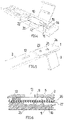
- FIGS. 1 to 3 show a reagent reservoir according to the invention composed of a plastic part and of a laminate film, with mutually movable components in different positions,
- FIGS. 4 and 5 show the plastic part of the work reservoir from FIGS. 1 to 3 in different perspective views
- FIGS. 6 and 7 show details of possible embodiments of the reagent reservoir from FIGS. 1 to 3 , in partial cross sections,
- FIGS. 7 and 8 show partial cross sections through reagent reservoirs according to the invention, combined with a carrier for a dry reagent,
- FIGS. 10 to 13 show partial cross sections through a reagent reservoir according to the invention, combined with a carrier for a sample to be analyzed,
- FIG. 14 shows a partial cross section through a reagent reservoir according to the invention, integrated in a lateral flow analysis chip for the analysis of liquids,
- FIG. 15 shows a reagent reservoir according to the invention integrated in a lateral flow analysis chip, combined with a carrier for a solid sample to be analyzed, and
- FIG. 16 shows a partial cross section through a reagent reservoir according to the invention, a lateral flow analysis chip being able to be inserted into the discharging chamber of said reagent reservoir.
- a reagent reservoir shown in FIGS. 1 to 3 comprises a substrate 1 produced by injection molding from PMMA, PC, PEEK, PP, PE, COC, PP or other plastics, preferably polyolefins.
- the substrate 1 is connected integrally in each case to a lid 2 and to an actuator 3 via a respective film hinge 4 , 5 .
- the substrate 1 is welded to a film 6 .
- this is a laminate film composed of a soft-annealed aluminum layer and a plastic layer.
- a bulge 7 of the film 6 forms a storage space 8 between the film 6 and the substrate 1 .
- the film 6 extends past the storage space 8 to an end opening 9 of a channel 10 , the latter communicating with the storage space 8 and opening into a discharging chamber and/or mixing chamber 18 of the reagent reservoir.
- a sealing wall 11 is located inside a widening 42 of the groove (best seen in FIG. 4 ), and the end edge of the sealing wall 11 directed toward the film 6 , like the surface of the substrate 1 covered by the film 6 , is welded to the film 6 .
- the lid 2 has an elongate opening 12 which lies opposite the storage space 8 , when the lid 2 is folded over onto the substrate 1 , and which is adapted to the elongate shape of the storage space 8 .
- the opening 12 is surrounded by an annular wall 13 which is produced integrally with the lid 2 and by which the storage space is enclosed all the way round when the lid 2 is folded over.
- a transverse wall 14 with niches 15 in which seat projections 16 in the substrate 1 engage when the lid 2 is folded over, ensures, together with a web projection 19 , a stable clamped fit of the lid 2 on the substrate 1 and a reproducible positioning of the opening 12 relative to the storage space 8 .
- FIG. 4 which shows the substrate 1 without the film 6
- a groove 20 is formed in the substrate 1 , said groove 20 surrounding the storage space 8 and further extending along the channel 10 .
- the groove 20 ensures a particularly firm weld connection that seals off the storage space 8 and the channel 10 .
- the substrate surface resting against the film 6 additionally has a furrowed structure (not shown).
- two opening channels 22 each comprising an attachment stub 21 , open into the storage space 8 .
- the attachment stubs 21 each protrude outward from the bottom of a depression 23 .
- the attachment stubs 21 can be welded in such a way that their free ends are set back in relation to the plane bottom surface 24 of the substrate 1 .
- the reservoir can thus be placed with its bottom surface 24 in a stable position on an even support surface.
- the actuator 3 can be pivoted through 180°, whereupon a stamp element 17 of the actuator 3 passes through the opening 12 and presses the storage space 8 together. As this happens, the weld between the film 6 and the edge of the sealing wall 11 tears, which results in the reagent being withdrawn in a controlled flow through the channel 10 .
- the stamp element 17 In its end position, the stamp element 17 almost reaches the surface of the substrate 1 and is only separated from the latter by the plastically deformed film 6 .
- the emptying of the storage space 8 through plastic deformation of the film 6 could also be effected by a stamp that forms part of an operating appliance.
- the substrate 1 if appropriate together with the lid 2 and with the actuator 3 , is produced in a single manufacturing step, preferably by injection molding.
- the production of the shaped film 6 takes place in a further step.
- the substrate 1 and the film 6 are welded to each other, and the storage space 8 and the channel 10 are thus formed.
- the fluid to be stored is introduced through the attachment stubs 21 and the openings 22 into the storage space 8 , such that the latter is almost completely filled, preferably filled to more than 95% of its storage volume.
- the attachment stubs 21 are welded in order to hermetically seal the storage space such that it is stable when stored.
- the effect of the heat during the welding is preferably controlled such that the welding procedure is completed in less than 5 seconds, in particular in less than 2 seconds, such that harmful heating of the stored reagent can be avoided as far as possible.
- the reagent reservoir described above can be varied in accordance with the illustrative embodiments described with reference to FIGS. 6 to 16 .
- FIG. 6 shows a detail of a reagent reservoir with a substrate 1 and with a lid 2 where, in contrast to the illustrative embodiment in FIGS. 1 to 5 , a storage space 8 is formed not by a bulge of the film 6 but by a depression 25 in the substrate 1 .
- the film 6 is composed of a laminate of an aluminum layer 26 and of a plastic layer 27 .
- the aluminum layer 26 directed away from the reservoir interior preferably has a thickness of between 10 and 150 ⁇ m, in particular between 30 and 100 ⁇ m.
- the so thickness of the plastic film 27 preferably made from PP or PE, is preferably between 10 and 100 ⁇ m, in particular between 20 and 50 ⁇ m.
- plastic material of the film 6 and the plastic material of the substrate 1 preferably match.
- a laminate with further layers could also be used, or alternatively, in order to form the storage chamber 8 , a single-layer or mufti-layer plastic film could be used.
- FIG. 7 shows the various possibilities for the formation of a storage space 8 .
- a storage space 8 is formed by a depression 25 in the substrate 1 , as in the illustrative embodiment in FIG. 6 .
- FIG. 7 b corresponds to the illustrative embodiment in FIGS. 1 to 5 , with a storage space 8 formed by a bulge 7 of the film 4 .
- FIG. 7 c shows a reagent reservoir with a storage space 8 which is formed both by a depression 25 in the substrate 1 and also by a bulge 7 in the film 6 .
- the sealing wall 11 preferably has an end face which is directed toward the film 6 and of which the width in the longitudinal direction of the channel is less than or equal to the thickness of a plastic layer of the film 6 welded to it.
- the volume of material to be melted during the welding is thereby reduced and the reproducibility of the weld is improved.
- Illustrative embodiments of a reagent reservoir shown in FIG. 8 each have a carrier element 28 for receiving dry reagent 29 , e.g. a primer, a reagent for lysis, or functionalized or magnetic beads, wherein, in the course of emptying of the reagent reservoir, a desired further reagent can be produced, by resuspension and mixing, from the dry reagent and from the fluid stored in the storage space 8 .
- the dry reagent 29 comes to be arranged in the channel 10 , such that it is washed off from the carrier element 28 by the fluid flowing from the storage space 8 .
- FIG. 9 shows an arrangement of the dry reagent 29 in the discharging chamber 18 .
- the chamber 18 in this case serving as mixing chamber, the dry reagent 29 is dissolved by the emerging fluid, e.g. by diffusion and incubation.
- This dissolution process can be supported by movement of the fluid (agitation), by mechanical means (not shown) or by fluid movements.
- dry reagent 29 is shown here as being introduced via the carrier element 28 , a dry reagent could also be introduced directly into the chamber 18 before closure of the lid 2 .
- the carrier elements 28 with the dry reagent can be prefabricated as separate parts and, in the course of the production of the reagent reservoir, can be mounted in a fluid-tight manner by means of a conical interference fit or by welding.
- Reagent reservoirs described in FIGS. 10 and 11 are combined with a sample carrier 30 via which a sample 31 to be analyzed, e.g. blood, saliva, urine, tissue, and also plant, food or soil samples, can be introduced into the reagent reservoir by the user in a convenient manner and, in particular, in the desired quantity.
- a sample 31 to be analyzed e.g. blood, saliva, urine, tissue, and also plant, food or soil samples
- the sample carrier 30 with the applied sample 31 can, in accordance with FIG. 10 , be fitted on the reagent reservoir in a fluid-tight manner via a plug connection, such that the sample 31 is arranged in the channel 10 and is washed round by the reagent withdrawn from the storage space 8 and at least partially resuspended.
- the sample carrier 30 is introduced into the reagent reservoir via a conical closure piece, e.g. corresponding to the Luer standard.
- the sample 31 washed from the sample carrier 30 by the reagent flowing over it is delivered for further analysis/processing after leaving the reagent reservoir.
- the sample can also be arranged in the discharging chamber 18 , where the sample is dissolved under diffusion and incubation and, if appropriate after mixing with a further fluid, is delivered for processing.
- the dissolution process can be supported by movement (agitation) of the fluid using mechanical means or by fluid movement.
- FIGS. 12 and 13 show illustrative embodiments with a plate-shaped sample carrier 32 for receiving a sample 33 to be analyzed.
- samples carriers known as “absorbent pads”, are preferably made of nitrocellulose, paper or other porous materials and are generally used to collect samples of bodily fluids, such as saliva, or in drugs tests.
- the sample carrier 32 is mounted on the underside of the reagent reservoir, where it delimits a portion 34 of the channel 10 routed on the underside of the substrate 1 .
- the sample 33 is also washed from the sample carrier 32 , by the fluid emerging from the storage space, and delivered for analysis/processing.
- the channel portion 34 can have a meandering, helical or fork-shaped configuration.
- the illustrative embodiment of FIG. 12 b differs from the illustrative embodiment of FIG. 12 a in that, in the channel portion 34 , needle-shaped elements 35 jut out of from the substrate and protrude into the sample 33 , thereby enlarging the surface of the area of the sample membrane over which the fluid flows and helping to force the sample 33 from the sample carrier 32 .
- a plate-shaped sample carrier 32 with a sample 33 adjoins the discharging chamber or mixing chamber 18 .
- FIG. 14 concerns a reagent reservoir which has an integrated analysis chip 36 , working according to the lateral flow principle, and has a housing in common with the analysis chip 36 .
- a lateral flow membrane 37 protrudes into the discharging chamber 18 of the reagent reservoir.
- the lateral flow membrane 37 can be wetted with a sample 39 , e.g. a blood sample, through an opening 38 .
- Reagent stored in the storage space 8 forms a buffer liquid for the analysis reactions in the lateral flow membrane.
- Costs are reduced by only a single housing being needed for reservoir and analysis chip.
- a solid or liquid sample 41 is brought into contact with a lateral flow membrane 37 by way of a sample carrier 40 .
- the solid sample 41 is flushed off and caused to react.
- FIG. 16 shows an illustrative embodiment in which a separate lateral flow analysis module 43 with a lateral flow membrane 37 can be inserted into the discharging chamber 18 of a reagent reservoir.
Abstract
Description
Claims (17)
Priority Applications (1)
| Application Number | Priority Date | Filing Date | Title |
|---|---|---|---|
| US16/215,282 US11364501B2 (en) | 2014-07-01 | 2018-12-10 | Reagent reservoir for fluids |
Applications Claiming Priority (6)
| Application Number | Priority Date | Filing Date | Title |
|---|---|---|---|
| EP14175207.1A EP2962758B1 (en) | 2014-07-01 | 2014-07-01 | Flow cell having a storage space and a transport channel that can be opened at a predetermined breaking point |
| EP14175207 | 2014-07-01 | ||
| EP14175207.1 | 2014-07-01 | ||
| PCT/EP2015/063997 WO2016000999A1 (en) | 2014-07-01 | 2015-06-22 | Reagent reservoir for fluids |
| US201615322891A | 2016-12-29 | 2016-12-29 | |
| US16/215,282 US11364501B2 (en) | 2014-07-01 | 2018-12-10 | Reagent reservoir for fluids |
Related Parent Applications (2)
| Application Number | Title | Priority Date | Filing Date |
|---|---|---|---|
| PCT/EP2015/063997 Continuation WO2016000999A1 (en) | 2014-07-01 | 2015-06-22 | Reagent reservoir for fluids |
| US15/322,891 Continuation US10183293B2 (en) | 2014-07-01 | 2015-06-22 | Reagent reservoir for fluids |
Publications (2)
| Publication Number | Publication Date |
|---|---|
| US20190118179A1 US20190118179A1 (en) | 2019-04-25 |
| US11364501B2 true US11364501B2 (en) | 2022-06-21 |
Family
ID=51136329
Family Applications (7)
| Application Number | Title | Priority Date | Filing Date |
|---|---|---|---|
| US15/322,891 Active US10183293B2 (en) | 2014-07-01 | 2015-06-22 | Reagent reservoir for fluids |
| US15/322,751 Active US10173215B2 (en) | 2014-07-01 | 2015-06-22 | Flow cell comprising a storage zone and a duct that can be opened at a predetermined breaking point |
| US16/203,039 Active 2036-06-04 US11642673B2 (en) | 2014-07-01 | 2018-11-28 | Flow cell comprising a storage zone and a duct that can be opened at a predetermined breaking point |
| US16/215,195 Active 2036-03-25 US11291996B2 (en) | 2014-07-01 | 2018-12-10 | Reagent reservoir for fluids |
| US16/215,282 Active 2036-02-17 US11364501B2 (en) | 2014-07-01 | 2018-12-10 | Reagent reservoir for fluids |
| US16/215,245 Active 2036-04-19 US11364500B2 (en) | 2014-07-01 | 2018-12-10 | Reagent reservoir for fluids |
| US18/187,560 Pending US20230219085A1 (en) | 2014-07-01 | 2023-03-21 | Flow cell comprising a storage zone and a duct that can be opened at a predetermined breaking point |
Family Applications Before (4)
| Application Number | Title | Priority Date | Filing Date |
|---|---|---|---|
| US15/322,891 Active US10183293B2 (en) | 2014-07-01 | 2015-06-22 | Reagent reservoir for fluids |
| US15/322,751 Active US10173215B2 (en) | 2014-07-01 | 2015-06-22 | Flow cell comprising a storage zone and a duct that can be opened at a predetermined breaking point |
| US16/203,039 Active 2036-06-04 US11642673B2 (en) | 2014-07-01 | 2018-11-28 | Flow cell comprising a storage zone and a duct that can be opened at a predetermined breaking point |
| US16/215,195 Active 2036-03-25 US11291996B2 (en) | 2014-07-01 | 2018-12-10 | Reagent reservoir for fluids |
Family Applications After (2)
| Application Number | Title | Priority Date | Filing Date |
|---|---|---|---|
| US16/215,245 Active 2036-04-19 US11364500B2 (en) | 2014-07-01 | 2018-12-10 | Reagent reservoir for fluids |
| US18/187,560 Pending US20230219085A1 (en) | 2014-07-01 | 2023-03-21 | Flow cell comprising a storage zone and a duct that can be opened at a predetermined breaking point |
Country Status (4)
| Country | Link |
|---|---|
| US (7) | US10183293B2 (en) |
| EP (2) | EP2962758B1 (en) |
| CN (1) | CN206454662U (en) |
| WO (2) | WO2016000999A1 (en) |
Families Citing this family (14)
| Publication number | Priority date | Publication date | Assignee | Title |
|---|---|---|---|---|
| GB2516667A (en) | 2013-07-29 | 2015-02-04 | Atlas Genetics Ltd | An improved cartridge, cartridge reader and method for preventing reuse |
| GB2516666B (en) | 2013-07-29 | 2015-09-09 | Atlas Genetics Ltd | Fluidic cartridge for nucleic acid amplification and detection |
| GB2516672B (en) | 2013-07-29 | 2015-05-20 | Atlas Genetics Ltd | A system and method for expelling liquid from a fluidic cartridge |
| GB2516669B (en) | 2013-07-29 | 2015-09-09 | Atlas Genetics Ltd | A method for processing a liquid sample in a fluidic cartridge |
| GB2516675A (en) | 2013-07-29 | 2015-02-04 | Atlas Genetics Ltd | A valve which depressurises, and a valve system |
| EP3263215B1 (en) * | 2016-06-30 | 2021-04-28 | ThinXXS Microtechnology AG | Device with a flow cell with reagent storage |
| EP3273234B1 (en) * | 2016-07-22 | 2021-12-01 | Bundesrepublik Deutschland, vertreten durch den Bundesminister für Wirtschaft und Energie | Sample carrier, analysis method and optical measuring device |
| WO2018122852A1 (en) | 2016-12-29 | 2018-07-05 | Schnell Amit | Cartridge for use in in-vitro diagnostics and method of use thereof |
| EP3406340B1 (en) * | 2017-05-26 | 2021-07-07 | Thinxxs Microtechnology Ag | Flow cell with housing component |
| USD840549S1 (en) * | 2017-06-19 | 2019-02-12 | Integra Biosciences Ag | Reagent reservoir kit |
| USD824534S1 (en) * | 2017-06-19 | 2018-07-31 | Integra Biosciences Ag | Reagent reservoir liner |
| US11008627B2 (en) | 2019-08-15 | 2021-05-18 | Talis Biomedical Corporation | Diagnostic system |
| TW202128281A (en) * | 2019-12-30 | 2021-08-01 | 美商伊路米納有限公司 | Actuation systems and methods for use with flow cells |
| CN117561121A (en) * | 2021-12-10 | 2024-02-13 | 伊鲁米那有限公司 | Reagent reservoirs and related systems and methods |
Citations (10)
| Publication number | Priority date | Publication date | Assignee | Title |
|---|---|---|---|---|
| WO2009071078A1 (en) | 2007-12-06 | 2009-06-11 | Thinxxs Microtechnology Ag | Microfluid storage device |
| US20100044918A1 (en) | 2008-08-22 | 2010-02-25 | Samsung Electronics Co., Ltd. | Method of preparing solid reagent and microfluidic device employing the solid reagent |
| US20100166609A1 (en) | 2008-12-26 | 2010-07-01 | Aida Engineering, Ltd. | Microchannel chip |
| DE102009009728A1 (en) | 2009-02-19 | 2010-09-02 | Thinxxs Microtechnology Ag | Flow cell with integrated fluid storage |
| DE102010042740A1 (en) | 2010-10-21 | 2012-04-26 | Ing. Erich Pfeiffer Gmbh | Discharge device for media |
| DE102011002571A1 (en) | 2011-01-12 | 2012-07-12 | Robert Bosch Gmbh | Reagent cartridge, processing chip, analysis kit and analysis method |
| DE102011003856A1 (en) | 2011-02-09 | 2012-08-09 | Robert Bosch Gmbh | Microsystem for fluidic applications and manufacturing method and method of use for a microsystem for fluidic applications |
| EP2647435A1 (en) | 2012-04-05 | 2013-10-09 | ThinXXS Microtechnology AG | Fluid cell with a tempering chamber |
| EP2679307A1 (en) | 2012-06-28 | 2014-01-01 | Thinxxs Microtechnology Ag | Microstorage device, in particular for integration into a microfluid flow cell |
| EP2687290A1 (en) | 2012-07-19 | 2014-01-22 | Robert Bosch Gmbh | Microfluidic storage device for storing a fluid, method for its manufacture and use of the same |
Family Cites Families (5)
| Publication number | Priority date | Publication date | Assignee | Title |
|---|---|---|---|---|
| WO2010009029A2 (en) | 2008-07-15 | 2010-01-21 | Wyeth | Methods for the preparation of azole compounds |
| DE102010014277B4 (en) | 2009-10-12 | 2020-03-12 | Mann+Hummel Gmbh | Filter device and main filter element for a filter device |
| AU2011221244B2 (en) * | 2010-02-23 | 2014-02-13 | Rheonix, Inc. | Self-contained biological assay apparatus, methods, and applications |
| FI122098B (en) | 2010-03-18 | 2011-08-31 | Outotec Oyj | Reactor and process purification process |
| EP2766642B1 (en) | 2011-10-10 | 2019-07-03 | KMT Waterjet Systems, Inc. | Gasketless high pressure connection |
-
2014
- 2014-07-01 EP EP14175207.1A patent/EP2962758B1/en active Active
-
2015
- 2015-06-22 WO PCT/EP2015/063997 patent/WO2016000999A1/en active Application Filing
- 2015-06-22 CN CN201590000762.XU patent/CN206454662U/en active Active
- 2015-06-22 EP EP15730198.7A patent/EP3164212B1/en active Active
- 2015-06-22 US US15/322,891 patent/US10183293B2/en active Active
- 2015-06-22 WO PCT/EP2015/063992 patent/WO2016000998A1/en active Application Filing
- 2015-06-22 US US15/322,751 patent/US10173215B2/en active Active
-
2018
- 2018-11-28 US US16/203,039 patent/US11642673B2/en active Active
- 2018-12-10 US US16/215,195 patent/US11291996B2/en active Active
- 2018-12-10 US US16/215,282 patent/US11364501B2/en active Active
- 2018-12-10 US US16/215,245 patent/US11364500B2/en active Active
-
2023
- 2023-03-21 US US18/187,560 patent/US20230219085A1/en active Pending
Patent Citations (18)
| Publication number | Priority date | Publication date | Assignee | Title |
|---|---|---|---|---|
| WO2009071078A1 (en) | 2007-12-06 | 2009-06-11 | Thinxxs Microtechnology Ag | Microfluid storage device |
| US9211538B2 (en) | 2007-12-06 | 2015-12-15 | Thinxxs Microtechnology Ag | Microfluid storage device |
| US20100044918A1 (en) | 2008-08-22 | 2010-02-25 | Samsung Electronics Co., Ltd. | Method of preparing solid reagent and microfluidic device employing the solid reagent |
| US20100166609A1 (en) | 2008-12-26 | 2010-07-01 | Aida Engineering, Ltd. | Microchannel chip |
| US9005546B2 (en) | 2009-02-19 | 2015-04-14 | Thinxxs Microtechnology Ag | Flow cell having integrated fluid reservoir |
| DE102009009728A1 (en) | 2009-02-19 | 2010-09-02 | Thinxxs Microtechnology Ag | Flow cell with integrated fluid storage |
| DE102010042740A1 (en) | 2010-10-21 | 2012-04-26 | Ing. Erich Pfeiffer Gmbh | Discharge device for media |
| DE102011002571A1 (en) | 2011-01-12 | 2012-07-12 | Robert Bosch Gmbh | Reagent cartridge, processing chip, analysis kit and analysis method |
| US20120214254A1 (en) | 2011-02-09 | 2012-08-23 | Robert Bosch Gmbh | Microsystem for Fluidic Applications, and Production Method and Usage Method for a Microsystem for Fluidic Applications |
| DE102011003856A1 (en) | 2011-02-09 | 2012-08-09 | Robert Bosch Gmbh | Microsystem for fluidic applications and manufacturing method and method of use for a microsystem for fluidic applications |
| US9309879B2 (en) | 2011-02-09 | 2016-04-12 | Robert Bosch Gmbh | Microsystem for fluidic applications, and production method and usage method for a microsystem for fluidic applications |
| EP2647435A1 (en) | 2012-04-05 | 2013-10-09 | ThinXXS Microtechnology AG | Fluid cell with a tempering chamber |
| US20130263940A1 (en) | 2012-04-05 | 2013-10-10 | Thinxxs Microtechnology Ag | Flow cell with a temperature-control chamber |
| US9149802B2 (en) | 2012-04-05 | 2015-10-06 | Thinxxs Microtechnology Ag | Flow cell with a temperature-control chamber |
| EP2679307A1 (en) | 2012-06-28 | 2014-01-01 | Thinxxs Microtechnology Ag | Microstorage device, in particular for integration into a microfluid flow cell |
| US9108192B2 (en) | 2012-06-28 | 2015-08-18 | Thinxxs Microtechnology Ag | Micro reservoir, particularly for integration in a microfluidic flow cell |
| EP2687290A1 (en) | 2012-07-19 | 2014-01-22 | Robert Bosch Gmbh | Microfluidic storage device for storing a fluid, method for its manufacture and use of the same |
| US9168524B2 (en) | 2012-07-19 | 2015-10-27 | Robert Bosch Gmbh | Microfluidic storage device for pre-storing of fluid, method for its production and a use thereof |
Also Published As
| Publication number | Publication date |
|---|---|
| US20190134628A1 (en) | 2019-05-09 |
| US10183293B2 (en) | 2019-01-22 |
| US20170157608A1 (en) | 2017-06-08 |
| US20170157611A1 (en) | 2017-06-08 |
| US10173215B2 (en) | 2019-01-08 |
| US20190111430A1 (en) | 2019-04-18 |
| CN206454662U (en) | 2017-09-01 |
| US20190105654A1 (en) | 2019-04-11 |
| US20230219085A1 (en) | 2023-07-13 |
| WO2016000998A1 (en) | 2016-01-07 |
| EP3164212B1 (en) | 2020-02-19 |
| WO2016000999A1 (en) | 2016-01-07 |
| US20190118179A1 (en) | 2019-04-25 |
| US11291996B2 (en) | 2022-04-05 |
| EP3164212A1 (en) | 2017-05-10 |
| EP2962758B1 (en) | 2017-07-19 |
| US11642673B2 (en) | 2023-05-09 |
| EP2962758A1 (en) | 2016-01-06 |
| US11364500B2 (en) | 2022-06-21 |
Similar Documents
| Publication | Publication Date | Title |
|---|---|---|
| US11364501B2 (en) | Reagent reservoir for fluids | |
| KR100883951B1 (en) | Device having a self sealing fluid port | |
| US10315197B2 (en) | Apparatus for transporting a fluid within a channel leg of a microfluidic element | |
| JP2011524313A (en) | Fluid measuring container | |
| JP3768486B2 (en) | Micro fluid handling equipment | |
| US9757724B2 (en) | Apparatus for hermetically sealed storage of liquids for a microfluidic system | |
| JP2014502236A (en) | Liquid packaging material, its use and method of supplying liquid to a fluidic assembly | |
| US9168524B2 (en) | Microfluidic storage device for pre-storing of fluid, method for its production and a use thereof | |
| US9033307B2 (en) | Valve for lab-on-a-chip systems, method for actuating and for producing valve | |
| CN211043403U (en) | Single-channel push irrigation type micro-fluidic chip | |
| US10350596B2 (en) | Micro-reagent handler and cartridge assembly | |
| US11426725B2 (en) | Flow cell having a reagent reservoir | |
| US11045802B2 (en) | Sample carrier | |
| JP2010517001A (en) | Microfluidic chip having side openings for fluid introduction | |
| JP2018059916A (en) | Micro flow passage chip | |
| JP6654874B2 (en) | Storage container, flow cartridge, and discharge mechanism | |
| JP7014592B2 (en) | Weighing structure and microchip | |
| EP3544790B1 (en) | Ultrasonic welding of a microfluidic device | |
| JP2024059629A (en) | Fluid Devices | |
| JP2021518259A (en) | Fluid device | |
| Chew et al. | Protocol Cycle Time Optimization on a Microfluidic Cartridge for DNA/RNA Extraction Application |
Legal Events
| Date | Code | Title | Description |
|---|---|---|---|
| AS | Assignment |
Owner name: THINXXS MICROTECHNOLOGY AG, GERMANY Free format text: ASSIGNMENT OF ASSIGNORS INTEREST;ASSIGNOR:WEBER, LUTZ;REEL/FRAME:047731/0573 Effective date: 20161117 |
|
| FEPP | Fee payment procedure |
Free format text: ENTITY STATUS SET TO UNDISCOUNTED (ORIGINAL EVENT CODE: BIG.); ENTITY STATUS OF PATENT OWNER: LARGE ENTITY |
|
| STPP | Information on status: patent application and granting procedure in general |
Free format text: DOCKETED NEW CASE - READY FOR EXAMINATION |
|
| STPP | Information on status: patent application and granting procedure in general |
Free format text: NON FINAL ACTION MAILED |
|
| STPP | Information on status: patent application and granting procedure in general |
Free format text: FINAL REJECTION MAILED |
|
| STPP | Information on status: patent application and granting procedure in general |
Free format text: RESPONSE AFTER FINAL ACTION FORWARDED TO EXAMINER |
|
| STPP | Information on status: patent application and granting procedure in general |
Free format text: ADVISORY ACTION MAILED |
|
| STPP | Information on status: patent application and granting procedure in general |
Free format text: DOCKETED NEW CASE - READY FOR EXAMINATION |
|
| STPP | Information on status: patent application and granting procedure in general |
Free format text: NOTICE OF ALLOWANCE MAILED -- APPLICATION RECEIVED IN OFFICE OF PUBLICATIONS |
|
| STPP | Information on status: patent application and granting procedure in general |
Free format text: PUBLICATIONS -- ISSUE FEE PAYMENT VERIFIED |
|
| AS | Assignment |
Owner name: THINXXS MICROTECHNOLOGY GMBH, GERMANY Free format text: CHANGE OF NAME;ASSIGNOR:THINXXS MICROTECHNOLOGY AG;REEL/FRAME:060383/0572 Effective date: 20211123 |
|
| STCF | Information on status: patent grant |
Free format text: PATENTED CASE |