EP3263215B1 - Device with a flow cell with reagent storage - Google Patents
Device with a flow cell with reagent storage Download PDFInfo
- Publication number
- EP3263215B1 EP3263215B1 EP16177162.1A EP16177162A EP3263215B1 EP 3263215 B1 EP3263215 B1 EP 3263215B1 EP 16177162 A EP16177162 A EP 16177162A EP 3263215 B1 EP3263215 B1 EP 3263215B1
- Authority
- EP
- European Patent Office
- Prior art keywords
- reagent
- flow cell
- carrier element
- reservoir region
- region
- Prior art date
- Legal status (The legal status is an assumption and is not a legal conclusion. Google has not performed a legal analysis and makes no representation as to the accuracy of the status listed.)
- Active
Links
- 239000003153 chemical reaction reagent Substances 0.000 title claims description 98
- 238000003860 storage Methods 0.000 title description 78
- 239000007788 liquid Substances 0.000 claims description 53
- 238000002156 mixing Methods 0.000 claims description 35
- 239000012530 fluid Substances 0.000 claims description 25
- 238000011010 flushing procedure Methods 0.000 claims description 10
- 230000004888 barrier function Effects 0.000 claims description 9
- 238000011144 upstream manufacturing Methods 0.000 claims 1
- 230000032258 transport Effects 0.000 description 27
- 239000000758 substrate Substances 0.000 description 12
- 239000010408 film Substances 0.000 description 11
- 239000004033 plastic Substances 0.000 description 8
- 229920003023 plastic Polymers 0.000 description 8
- 239000013039 cover film Substances 0.000 description 6
- 239000011534 wash buffer Substances 0.000 description 6
- 238000009423 ventilation Methods 0.000 description 5
- 230000015572 biosynthetic process Effects 0.000 description 4
- 239000000203 mixture Substances 0.000 description 4
- 238000003466 welding Methods 0.000 description 4
- 238000000576 coating method Methods 0.000 description 3
- 238000011049 filling Methods 0.000 description 3
- 230000002209 hydrophobic effect Effects 0.000 description 3
- 238000004519 manufacturing process Methods 0.000 description 3
- 238000005406 washing Methods 0.000 description 3
- 238000004026 adhesive bonding Methods 0.000 description 2
- 239000011248 coating agent Substances 0.000 description 2
- 239000011888 foil Substances 0.000 description 2
- 230000005661 hydrophobic surface Effects 0.000 description 2
- 239000000463 material Substances 0.000 description 2
- 229920003229 poly(methyl methacrylate) Polymers 0.000 description 2
- 239000004926 polymethyl methacrylate Substances 0.000 description 2
- 239000000126 substance Substances 0.000 description 2
- 102000004190 Enzymes Human genes 0.000 description 1
- 108090000790 Enzymes Proteins 0.000 description 1
- 239000012807 PCR reagent Substances 0.000 description 1
- 239000004696 Poly ether ether ketone Substances 0.000 description 1
- 239000002250 absorbent Substances 0.000 description 1
- 230000002745 absorbent Effects 0.000 description 1
- 239000002253 acid Substances 0.000 description 1
- 150000007513 acids Chemical class 0.000 description 1
- 230000009471 action Effects 0.000 description 1
- 230000004913 activation Effects 0.000 description 1
- 239000000853 adhesive Substances 0.000 description 1
- 230000001070 adhesive effect Effects 0.000 description 1
- 230000002411 adverse Effects 0.000 description 1
- 150000001298 alcohols Chemical class 0.000 description 1
- XAGFODPZIPBFFR-UHFFFAOYSA-N aluminium Chemical compound [Al] XAGFODPZIPBFFR-UHFFFAOYSA-N 0.000 description 1
- 229910052782 aluminium Inorganic materials 0.000 description 1
- 239000002585 base Substances 0.000 description 1
- 239000011324 bead Substances 0.000 description 1
- JUPQTSLXMOCDHR-UHFFFAOYSA-N benzene-1,4-diol;bis(4-fluorophenyl)methanone Chemical compound OC1=CC=C(O)C=C1.C1=CC(F)=CC=C1C(=O)C1=CC=C(F)C=C1 JUPQTSLXMOCDHR-UHFFFAOYSA-N 0.000 description 1
- 239000000872 buffer Substances 0.000 description 1
- 238000006243 chemical reaction Methods 0.000 description 1
- 238000004891 communication Methods 0.000 description 1
- 230000006835 compression Effects 0.000 description 1
- 238000007906 compression Methods 0.000 description 1
- 238000003851 corona treatment Methods 0.000 description 1
- 230000003111 delayed effect Effects 0.000 description 1
- 239000013024 dilution buffer Substances 0.000 description 1
- 238000007598 dipping method Methods 0.000 description 1
- 238000007599 discharging Methods 0.000 description 1
- 238000001035 drying Methods 0.000 description 1
- 230000000694 effects Effects 0.000 description 1
- 239000007850 fluorescent dye Substances 0.000 description 1
- 239000012634 fragment Substances 0.000 description 1
- 238000009652 hydrodynamic focusing Methods 0.000 description 1
- 230000005660 hydrophilic surface Effects 0.000 description 1
- 238000003780 insertion Methods 0.000 description 1
- 230000037431 insertion Effects 0.000 description 1
- 230000007774 longterm Effects 0.000 description 1
- 239000012139 lysis buffer Substances 0.000 description 1
- 238000005259 measurement Methods 0.000 description 1
- 238000000034 method Methods 0.000 description 1
- 229920002530 polyetherether ketone Polymers 0.000 description 1
- 229920001296 polysiloxane Polymers 0.000 description 1
- 238000003825 pressing Methods 0.000 description 1
- 230000008569 process Effects 0.000 description 1
- 238000007789 sealing Methods 0.000 description 1
- 238000004904 shortening Methods 0.000 description 1
- 239000000243 solution Substances 0.000 description 1
- 239000004094 surface-active agent Substances 0.000 description 1
- 238000003786 synthesis reaction Methods 0.000 description 1
- 229920002725 thermoplastic elastomer Polymers 0.000 description 1
- 238000013022 venting Methods 0.000 description 1
- XLYOFNOQVPJJNP-UHFFFAOYSA-N water Substances O XLYOFNOQVPJJNP-UHFFFAOYSA-N 0.000 description 1
- 238000009736 wetting Methods 0.000 description 1
- 239000000080 wetting agent Substances 0.000 description 1
Images


Classifications
-
- B—PERFORMING OPERATIONS; TRANSPORTING
- B01—PHYSICAL OR CHEMICAL PROCESSES OR APPARATUS IN GENERAL
- B01L—CHEMICAL OR PHYSICAL LABORATORY APPARATUS FOR GENERAL USE
- B01L3/00—Containers or dishes for laboratory use, e.g. laboratory glassware; Droppers
- B01L3/50—Containers for the purpose of retaining a material to be analysed, e.g. test tubes
- B01L3/502—Containers for the purpose of retaining a material to be analysed, e.g. test tubes with fluid transport, e.g. in multi-compartment structures
- B01L3/5027—Containers for the purpose of retaining a material to be analysed, e.g. test tubes with fluid transport, e.g. in multi-compartment structures by integrated microfluidic structures, i.e. dimensions of channels and chambers are such that surface tension forces are important, e.g. lab-on-a-chip
- B01L3/502715—Containers for the purpose of retaining a material to be analysed, e.g. test tubes with fluid transport, e.g. in multi-compartment structures by integrated microfluidic structures, i.e. dimensions of channels and chambers are such that surface tension forces are important, e.g. lab-on-a-chip characterised by interfacing components, e.g. fluidic, electrical, optical or mechanical interfaces
-
- B—PERFORMING OPERATIONS; TRANSPORTING
- B01—PHYSICAL OR CHEMICAL PROCESSES OR APPARATUS IN GENERAL
- B01L—CHEMICAL OR PHYSICAL LABORATORY APPARATUS FOR GENERAL USE
- B01L3/00—Containers or dishes for laboratory use, e.g. laboratory glassware; Droppers
- B01L3/50—Containers for the purpose of retaining a material to be analysed, e.g. test tubes
- B01L3/502—Containers for the purpose of retaining a material to be analysed, e.g. test tubes with fluid transport, e.g. in multi-compartment structures
- B01L3/5027—Containers for the purpose of retaining a material to be analysed, e.g. test tubes with fluid transport, e.g. in multi-compartment structures by integrated microfluidic structures, i.e. dimensions of channels and chambers are such that surface tension forces are important, e.g. lab-on-a-chip
- B01L3/502746—Containers for the purpose of retaining a material to be analysed, e.g. test tubes with fluid transport, e.g. in multi-compartment structures by integrated microfluidic structures, i.e. dimensions of channels and chambers are such that surface tension forces are important, e.g. lab-on-a-chip characterised by the means for controlling flow resistance, e.g. flow controllers, baffles
-
- B—PERFORMING OPERATIONS; TRANSPORTING
- B01—PHYSICAL OR CHEMICAL PROCESSES OR APPARATUS IN GENERAL
- B01L—CHEMICAL OR PHYSICAL LABORATORY APPARATUS FOR GENERAL USE
- B01L3/00—Containers or dishes for laboratory use, e.g. laboratory glassware; Droppers
- B01L3/52—Containers specially adapted for storing or dispensing a reagent
- B01L3/523—Containers specially adapted for storing or dispensing a reagent with means for closing or opening
-
- B—PERFORMING OPERATIONS; TRANSPORTING
- B01—PHYSICAL OR CHEMICAL PROCESSES OR APPARATUS IN GENERAL
- B01L—CHEMICAL OR PHYSICAL LABORATORY APPARATUS FOR GENERAL USE
- B01L2200/00—Solutions for specific problems relating to chemical or physical laboratory apparatus
- B01L2200/02—Adapting objects or devices to another
- B01L2200/026—Fluid interfacing between devices or objects, e.g. connectors, inlet details
- B01L2200/027—Fluid interfacing between devices or objects, e.g. connectors, inlet details for microfluidic devices
-
- B—PERFORMING OPERATIONS; TRANSPORTING
- B01—PHYSICAL OR CHEMICAL PROCESSES OR APPARATUS IN GENERAL
- B01L—CHEMICAL OR PHYSICAL LABORATORY APPARATUS FOR GENERAL USE
- B01L2200/00—Solutions for specific problems relating to chemical or physical laboratory apparatus
- B01L2200/16—Reagents, handling or storing thereof
-
- B—PERFORMING OPERATIONS; TRANSPORTING
- B01—PHYSICAL OR CHEMICAL PROCESSES OR APPARATUS IN GENERAL
- B01L—CHEMICAL OR PHYSICAL LABORATORY APPARATUS FOR GENERAL USE
- B01L2300/00—Additional constructional details
- B01L2300/04—Closures and closing means
- B01L2300/041—Connecting closures to device or container
- B01L2300/044—Connecting closures to device or container pierceable, e.g. films, membranes
-
- B—PERFORMING OPERATIONS; TRANSPORTING
- B01—PHYSICAL OR CHEMICAL PROCESSES OR APPARATUS IN GENERAL
- B01L—CHEMICAL OR PHYSICAL LABORATORY APPARATUS FOR GENERAL USE
- B01L2300/00—Additional constructional details
- B01L2300/04—Closures and closing means
- B01L2300/046—Function or devices integrated in the closure
- B01L2300/047—Additional chamber, reservoir
-
- B—PERFORMING OPERATIONS; TRANSPORTING
- B01—PHYSICAL OR CHEMICAL PROCESSES OR APPARATUS IN GENERAL
- B01L—CHEMICAL OR PHYSICAL LABORATORY APPARATUS FOR GENERAL USE
- B01L2300/00—Additional constructional details
- B01L2300/08—Geometry, shape and general structure
- B01L2300/0861—Configuration of multiple channels and/or chambers in a single devices
- B01L2300/0867—Multiple inlets and one sample wells, e.g. mixing, dilution
-
- B—PERFORMING OPERATIONS; TRANSPORTING
- B01—PHYSICAL OR CHEMICAL PROCESSES OR APPARATUS IN GENERAL
- B01L—CHEMICAL OR PHYSICAL LABORATORY APPARATUS FOR GENERAL USE
- B01L2300/00—Additional constructional details
- B01L2300/08—Geometry, shape and general structure
- B01L2300/0861—Configuration of multiple channels and/or chambers in a single devices
- B01L2300/0877—Flow chambers
-
- B—PERFORMING OPERATIONS; TRANSPORTING
- B01—PHYSICAL OR CHEMICAL PROCESSES OR APPARATUS IN GENERAL
- B01L—CHEMICAL OR PHYSICAL LABORATORY APPARATUS FOR GENERAL USE
- B01L2300/00—Additional constructional details
- B01L2300/08—Geometry, shape and general structure
- B01L2300/0861—Configuration of multiple channels and/or chambers in a single devices
- B01L2300/0883—Serpentine channels
-
- B—PERFORMING OPERATIONS; TRANSPORTING
- B01—PHYSICAL OR CHEMICAL PROCESSES OR APPARATUS IN GENERAL
- B01L—CHEMICAL OR PHYSICAL LABORATORY APPARATUS FOR GENERAL USE
- B01L2300/00—Additional constructional details
- B01L2300/16—Surface properties and coatings
- B01L2300/161—Control and use of surface tension forces, e.g. hydrophobic, hydrophilic
Definitions
- the invention relates to a device with at least one storage area containing a liquid reagent, the storage area being delimited by a carrier element introduced into an opening in a flow cell together with the reagent, the carrier element sealing off the storage area from the outside in a fluid-tight manner, the storage area connecting the liquid reagent the carrier element holding the vessel and / or capillary structure and wherein the storage area is connected to at least one transport channel located in the flow cell.
- microfluidic flow cells are increasingly used in diagnostics, analysis and / or synthesis of substances, especially in the life sciences. It is known that such flow cells often process very small volumes of reagents which interact with the samples to be analyzed or processed and which are to be introduced into the flow cells in the course of the production or use of the flow cells.
- Reagents can be stored within flow cells in storage spaces, transport channels or containers placed in the flow cells.
- blisters closed by predetermined break barriers come into consideration, which are preferably made of aluminum laminates.
- the capacity of such blisters can neither be reduced nor reduced at will enlarge.
- Liquid reagents can be, for example, fluorescent dyes, acids, bases, alcohols, bead solutions, lysis buffers, antibodies, enzymes, DNA fragments, PCR reagent mixtures or washing buffers.
- Flow cells that have the features specified in the preamble of claim 1 are from US 2013/299041 A1 , EP 1285 628 A2 , US 2013/302842 A1 , EP1203959 A1 as EP 2 821 138 A1 known.
- the storage area is connected to a channel discharging the liquid reagent from the storage area.
- the invention is based on the object of creating a new device of the type mentioned at the beginning with a storage area for small liquid reagent volumes, which can be produced with less effort than the prior art.
- the device according to the invention which achieves this object is characterized in that the storage area is connected to a further transport channel of the flow cell and that a groove or a channel of the vessel and / or capillary structure is aligned with the transport channel and the further transport channel in such a way that a flushing flow can flow through the storage area.
- the present invention advantageously allows a small volume of a liquid reagent to be introduced into the flow cell both in the course of production and use of a flow cell, preferably reagent volumes between 1 and 100 microliters, in particular between 5 and 50 microliters. Complex ventilation channels that have to be sealed can be avoided.
- the reagent to be stored can be conveniently applied in the vessel and / or capillary structure of the carrier element outside the flow cell by pipetting or dipping onto the carrier element.
- the storage area within a flow cell is hermetically sealed against internal cavities of the flow cell by at least one predetermined breaking barrier. In this way, the flow cell provided with the liquid reagent can be stored for a long time.
- the carrier element can be connected to the flow cell solely by force and / or form fit, e.g. when the liquid reagent is introduced into the flow cell in the course of using the flow cell.
- the flow cell is welded and / or glued to the flow cell in a connection area arranged at a distance from the reagent. Due to the distance between the connection area and the reagent, adverse effects on the reagent due to welding heat or adhesive vapors can be avoided.
- a predetermined breaking barrier hermetically enclosing the reagent can be formed in each of the channels.
- the opening is preferably formed in a plate-shaped substrate of the flow cell and the flow cell comprises, in particular, a cover connected to the substrate, in particular a cover film, which covers the opening and possibly the at least one transport channel.
- the storage area can be limited within the flow cell solely by the vessel and / or capillary structure of the carrier element or by the vessel and / or capillary structure and the cover.
- the reagent with a free liquid surface adjoins an interior space of a chamber, in particular a mixing chamber, formed in the flow cell.
- the carrier element is preferably designed in the manner of a plug which fills the opening with an end face having the vessel and / or capillary structure.
- the carrier element has a conical section which can ensure a tight closure of the storage area with sufficient ventilation of the storage area.
- the carrier element is expediently provided with handling devices on an outside facing away from the storage area and comprises in particular a seat for connection to an assembly tool.
- the handling devices can be useful both when filling the vessel and / or capillary structure and when assembling the carrier element containing the reagent.
- the carrier element has, on an outer side facing away from the storage area, a collar which forms the abovementioned connecting area and via which a welding and / or gluing to the flow cell can take place.
- the groove or the channel is preferably open at at least one end to a lateral surface of the carrier element.
- devices are provided for detaching the liquid reagent from the vessel and / or capillary structure by means of an inertial force, in particular centrifugal force.
- an inertial force in particular centrifugal force.
- the flow cell can be set in rotation during use, e.g. by an operator device.
- a fluid provided in the mixing chamber can wash off the liquid reagent, in particular by shaking the flow cell.
- the liquid reagent can be washed off in the mixing chamber by rinsing it over one or more times while moving a sample liquid or another mixed or rinsing liquid to and fro.
- the transport channel leading to the storage area and the transport channel leading away from the storage area are connected by a bypass bypassing the storage area. Air present between the liquid reagent and a flushing flow can thus flow past the storage area. If the flow cross-section of the bypass is smaller than that of the storage area, the reagent is completely washed out with the flushing fluid.
- the flow cross-section of the storage area is smaller than the flow cross-section of a transport channel of the flow cell leading to the storage area and / or leading away from the storage area.
- the flow cross-section of the bypass can also be larger than the flow cross-section of the storage area, so that any delayed or gradual flushing that may be desired takes place over a longer period of time.
- the carrier element can be rotatably connected to the flow cell and, for example, have a stop, by means of which the aforementioned alignment of the storage area in relation to the channels is secured.
- At least the vessel and / or capillary structure of the carrier element has a hydrophilic surface through which a desired reagent volume can be measured more precisely when wetted with the liquid reagent.
- the vessel and / or channel structure of the carrier element can also be adjoined by a hydrophobic surface of the carrier element in order to achieve a sharp contrast between wettability and non-wettability.
- a carrier element could also form several storage areas within a flow cell.
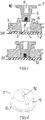
- the flow cell shown in detail comprises a plate-shaped substrate 1 which is glued or welded to a foil 2 on one side of the plate. Recesses in the substrate 1 that are open towards the film 2 form a structure of transport channels and chambers that is covered by the film 2 and is typical of flow cells, of which in FIG Fig. 1 a transport channel 3 is visible in cross section.
- the transport channel 3 opens into a through opening 4 which is closed at one end by the film 2 and has a conical section 5. The latter is extended by an annular attachment 6 connected to the substrate 1.
- the mouth of the transport channel 3 is a mouth of another, in Fig. 1 not visible transport channel diametrically opposite.
- a carrier element 7 for a liquid reagent 8 can be inserted into the through opening 4.
- the carrier element 7, which is rotationally symmetrical in the exemplary embodiment shown, has a lateral surface 9 corresponding to the through opening 4 and is provided on its outside with a circumferential collar 10.
- a recess 11 opening out towards the outer surface of the carrier element 7 serves as a seat for receiving a handling tool.
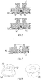
- the carrier element 7 On its end face facing away from the outer surface, the carrier element 7 has a vessel and / or capillary structure in the form of a groove 12, as shown on the basis of FIG Fig. 2 , which shows a similar carrier element 7, can be seen.
- the groove 12 is open towards both the end face and the lateral surface 9 of the carrier element 7.
- the liquid reagent 8 is applied to the carrier element 7, for example by pipetting or immersing the carrier element in a reagent supply, where it is held in the groove 12 by capillary forces. Even after the carrier element 7 has been introduced into the through opening 4 and the collar 10 has been welded and / or glued to the ring attachment 6, the liquid remains Reagent 8 initially in the groove 12 covered by the film 2, which together with the film 2, to which the carrier element 7 reaches, forms a storage area 13 within the now completed flow cell.
- the storable liquid volume of such a storage area 13 is between 1 and 100 microliters, preferably between 2 and 20 microliters.
- the substrate 1 and the cover film 2 are preferably made of a plastic, in particular the same plastic, e.g. PMMA, PC, COC, COP, PP or PE.
- a plastic in particular the same plastic, e.g. PMMA, PC, COC, COP, PP or PE.
- injection-molded carrier element in particular COC, PP, PET, PE, PMMA, PC, PEEK, TPE or silicone come into consideration as plastic.
- the carrier element 7 can also consist of the same plastic material as the substrate 1 and / or the cover film 2.
- the substrate preferably consists of a more brittle plastic, such as PC or COC, the carrier element 7 of a more ductile material, such as PE or PP, in order to make the conical press connection more pressure-resistant.
- the liquid reagent 8 is removed from the storage area 13 if necessary, e.g. by means of a further fluid flowing in via the transport channel 3, e.g. a sample to be analyzed or another stored reagent, e.g. a washing or dilution buffer.
- the further fluid displaces the liquid reagent 8 from the storage area 13, which is aligned with the channel 3, into the mentioned, diametrically opposite transport channel and can mix there with the stored reagent.
- a bypass 14 can be used for this purpose, which according to FIG Fig. 3a can be formed by reducing the diameter of a cylindrical end piece 15 of the carrier element 7.
- the bypass 14, 14 ' is also filled with rinsing liquid. Since the flow cross-section of the bypass 14, 14 'is smaller than the flow cross-section in the storage area 13, there is a lower flow resistance in the storage area 13 and the rinsing liquid transports the liquid reagent 8 out of the storage area.
- the opening or opening channel is preferably aligned with the groove 12 forming the vessel and / or capillary structure, the cross-sections preferably having a width of 0.05 to 2 mm and a height of 0.1 to 3 mm.
- bypasses could also be formed in that the cover film 2 is not firmly connected to the substrate up to the edge of the through opening 4 and can be deflected by external means, e.g. by negative pressure, to form ventilation slots.
- the flow cross-section of the side vents as shown in Fig. 3a shown could also be larger than the corresponding cross section of the storage area 13, so that more rinsing liquid is transported through the ventilation slots and the reagent is dispensed over a longer period of time. In this way, the reagent and rinsing liquid can be intensively mixed.
- the cross section of the storage area can be smaller than the cross section of the transport channels that are in fluid connection with the storage area, as shown in FIG Fig. 4 is indicated.
- the reagent is to a certain extent centered in the rinsing liquid, for example in the sense of hydrodynamic focusing.
- the storage area 13 forms exclusively a passage through the cylindrical end piece 15 of the carrier element.
- FIG. 7 shows a carrier element 7 which extends from the carrier element of FIG Fig. 2 differs in that two intersecting receiving grooves 12 and 12 'are provided to form a vessel and / or capillary structure.
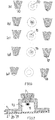
- FIG. 6 For the sake of simplicity, only the ends of carrier elements with a vessel and / or capillary structure are shown.
- Figure 6a shows a carrier element with a central, pocket-shaped recess 50, which is centrally located in the end face of a plug-shaped support element is formed.
- the reagent wets the recess 50 and forms a reproducible drop shape.
- the recess is accessible from one side in order to rinse the reagent out of the recess; the exemplary embodiment is particularly suitable for use in connection with a mixing chamber, as will be explained below.
- a microstructured surface is not formed, which has, for example, columns or grooves in a grid dimension between 10 and 500 micrometers, preferably 20 and 200 micrometers.
- the surface is preferably enlarged by hydrophilization and the wetting properties are improved, which means better control of the drop formation of the sample and thus better reproducibility of the dimensions of the reagent.
- the reagent can be rinsed out from one side.
- Figure 6c shows a groove channel 16 which is open on three sides and has cross-sectional dimensions of typically 0.12 ⁇ 0.12 mm 2 to 2 ⁇ 2 mm 2 .
- the channel area is hydrophilically modified. Smaller channel dimensions allow better control of the wettability and thus reproducibility of the measured amounts of reagent.
- the beginning and end of the meandering meandering channel can be connected to a flushing channel.
- Fig. 6d differs from the embodiment of FIG Figure 6c in that the meandering meandering channel 16 is covered by a film 17 made of plastic, which forms part of the two-part carrier element in this case.
- the foil 17 offers protection for the reagent before the mounting of the carrier element.
- the surfaces delimiting the channel 16 can, as in the embodiment of FIG Figure 6c , be wholly or partially modified to be hydrophilic.
- reagent quantities can be measured precisely, in that the capillary action does not allow the channel 16 to be overfilled or underfilled.
- the channel 16 can also be integrated into a flushing channel for emptying.
- Figure 6e shows a two-part reagent carrier element with a vessel and / or capillary structure, which is formed by an absorbent fleece 18 which absorbs the reagent in a capillary manner.
- the absorbed reagent can, for example, be released from the storage area within a mixing chamber by squeezing it out. Also a replacement by rinsing would be possible, for example, if a particularly slow release of the reagent is desired.
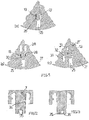
- Fig. 7 shows a detail of a flow cell which is formed from a substrate 1 and a cover film 2 and in which a mixing chamber 19 is provided.
- a carrier element 7 with a liquid reagent 8 protrudes into the mixing chamber 19.
- the mixing chamber 19 is also connected to a transport channel 20, in which a predetermined breaking lock 21 is formed, which hermetically seals the mixing chamber 19.
- the predetermined breaking barrier 21 formed by welding a projection of the substrate 1 to the film 2 can be unlocked by pressure of the liquid in the mixing chamber 19 or by means that act on the flow cell from the outside.
- Liquid present in the mixing chamber 19 can wash out the reagent, which can be supported, for example, by shaking movements of the flow cell.
- Fig. 8 shows a detail of a flow cell made of a substrate 1, a film 2 and a reagent carrier element 7.
- a storage area 13 for a liquid reagent 8 is formed within a transport channel 3 and aligned with the transport channel.
- the storage area 13 is hermetically sealed against the rest of the flow cell by a predetermined breaking block 21 'or 21''with a view to long-term storage of the flow cell before use.
- the storage element 7 has a stop element 22 for the precise alignment of the storage area 13 with the transport channel 3, for example by rotating the carrier element 7, which in this case is rotatably connected to the flow cell.
- Fig. 9 shows a detail of a plan view of a flow cell with a channel area 23 in which a reagent carrier element 7 forms a storage area for a reagent 8.
- the channel region 23 is designed in a meandering shape, with a widening 24 being formed downstream to further improve the mixing.
- the washing out can also be assisted by transporting the transport fluid back and forth.
- a section of a flow cell with a channel region 23 and two mixing chambers 19 ′, 19 ′′ shows Fig. 10 .
- washable storage areas are formed by reagent carrier elements 7 ', 7 "and 7"'.
- Fig. 11 shows excerpts of flow cells in the form of a round disk or a disk segment.
- the flow cells are designed to work with an operator device that rotates the flow cells.
- a mixing or reaction chamber 25 is located radially further outward than a storage area 13 formed by a carrier element.
- the mixing chamber 25 is also connected to a channel 27 for the supply of, for example, a sample and / or the discharge of the mixture from the mixing chamber, for example by pneumatic actuation.
- the transport of the reagent into the mixing chamber takes place through the centrifugal force generated during the rotation of the flow cell, whereby the predetermined breaking lock 26 is also opened through the pressure of the reagent.
- the breaking barrier could be unlocked by external means.
- Figure 11b shows a flow cell provided for rotation with two storage chambers 28, for example for a washing buffer or other liquid reagents.
- the storage chambers 28 are each separated from a storage area 13 by a predetermined breaking barrier 29, the two storage areas 13 being connected to the mixing chamber 25, which is connected to a supply and discharge channel 27, via further predetermined breaking barriers 30.
- the washing buffer for example, is transferred into the mixing chamber while rinsing out the storage areas, with the predetermined breaking barriers 29, 30 being able to be unlocked by the fluid pressure or other means.
- the flow cell shown and provided for rotation also has a blister memory 31 for a wash buffer, which is arranged radially further out than a storage area 13 using the structural space of the flow cell.
- a predetermined breaking lock 32 opens.
- the buffer is transferred into an antechamber 33 which is arranged radially further inward than the storage area 13.
- Fig. 12 shows a reagent carrier 7, in which not only the vessel and / or capillary structure is hydrophilized, but also the entire, the vessel and / or an end face having a capillary structure and a conical jacket surface 34.
- the hydrophilization is formed by a vitreous layer with a contact angle to water of less than 50 °.
- Changes to the surface properties of the plastic forming the carrier element can be made wet-chemically by applying wetting agents or surfactants and then drying (hydrophilic or hydrophobic).
- surface activation by means of plasma, flame or corona treatment can be carried out.
- Surface coatings by plasma polymerisation e.g. glass-like layers, hydrophilic or hydrophobic, or combinations thereof, can be applied locally over the entire area / completely or masked.
- Hydrophilization coating applied outside the vessel and / or capillary structure could be coated with a hydrophobic coating of the carrier element in this area, the typical contact angle being greater than 100 ° in order to emphasize the contrast of wettability and thus further refine the measurement of reagent quantities.
- Fig. 13 shows a reagent carrier element 7 with a channel structure 35 which forms the storage area and which is formed by covering a groove open on three sides with a film 36.
- the channel walls of the channel structure 35, which is open on both sides, including the film 36, are hydrophilized, for example by wet chemical treatment.
- Fig. 14 shows a two-part reagent carrier element made of a plastic injection-molded part 39 and a film 36, which has two conical sections 39, 39 'for insertion into two corresponding openings in a flow cell.
- a capillary channel 40 of one of the conical sections serves as a vessel and / or capillary structure for receiving a liquid reagent 8.
- the channel 40 is connected via a channel 41 to a channel 42 which is guided through the further conical section.
- the channel 40 which forms a storage area, can be integrated into a flushing channel of the flow cell via the channels 42 and 41.
- the flow cell shown in detail has a storage area 13 for a liquid reagent, as described above.
- the storage area 13 is connected to a supply channel 43 for a fluid for flushing out the liquid reagent from the storage area 13.
- the supply channel 43 is in Connection to a pressure source, not shown.
- the mixing chamber 45 is either permanently closed or has a closure valve (not shown) that extends through an operator device for the flow cell can be operated.
- the pressure source conveys the fluid with the rinsed off reagent into the mixing chamber 45, in which a counterpressure to the pressure source builds up through compression of the air contained therein.
- the pressure of the pressure source can be varied so that the counterpressure built up in the mixing chamber 45 reverses the movement of the fluid with the rinsed reagent and the fluid with the rinsed reagent can be moved back and forth with intensive mixing by varying the pressure of the pressure source .
- FIG. 16 The flow cell shown in detail with a storage area 13 for a liquid reagent has a mechanically actuatable blister 46 as a pressure source, which is connected to the storage area 13 via a predetermined break lock 47 in a supply line 43.
- the blister 46 contains a fluid by means of which the liquid reagent can be flushed out of the storage area 13.
- a valve 48 which can be actuated by an operator device is provided in a discharge line 44. Between the storage area 13 and the valve 48, the discharge line 44 is in communication with a storage chamber 49.
- the fluid presses against the predetermined breaking lock 47 and unlocks the predetermined breaking lock 47.
- the valve 48 is closed, the fluid with the reagent that has been rinsed off is conveyed into the storage chamber 49, in which a counterpressure builds up.
- the counterpressure can be used to transport the fluid with the rinsed off reagent back into the blister 46, the wall of the blister expanding again.
- the fluid with the rinsed off reagent is moved back and forth with intensive mixing. The mixture can then be transported away via the opened valve 49 for further use within the flow cell.
- carrier elements for a liquid sample to be analyzed could also be used.
- Carrier elements for a dry reagent would also come into consideration.
- a vessel and / or capillary structure can also be formed merely by a hydrophilized carrier surface, in particular a circular carrier surface, to which a hydrophobic surface is possibly adjacent.
Description
Die Erfindung betrifft eine Vorrichtung mit wenigstens einem ein flüssiges Reagenz enthaltenden Speicherbereich, wobei der Speicherbereich durch ein in eine Öffnung in einer Flusszelle gemeinsam mit dem Reagenz eingebrachtes Trägerelement begrenzt ist, das Trägerelement den Speicherbereich nach außen fluiddicht abschließt, der Speicherbereich eine das flüssige Reagenz an dem Trägerelement haltende Gefäß- oder/und Kapillarstruktur aufweist und wobei der Speicherbereich mit wenigstens einem sich in der Flusszelle befindendem Transportkanal in Verbindung steht.The invention relates to a device with at least one storage area containing a liquid reagent, the storage area being delimited by a carrier element introduced into an opening in a flow cell together with the reagent, the carrier element sealing off the storage area from the outside in a fluid-tight manner, the storage area connecting the liquid reagent the carrier element holding the vessel and / or capillary structure and wherein the storage area is connected to at least one transport channel located in the flow cell.
Bekanntermaßen kommen mikrofluidische Flusszellen in zunehmendem Maße bei der Diagnostik, Analytik und/oder Synthese von Substanzen vor allem in den Life Sciences zum Einsatz. Bekanntermaßen verarbeiten solche Flusszellen oft sehr kleine Volumina von Reagenzien, die mit den zu analysierenden oder zu verarbeiteten Proben interagieren und die im Zuge der Fertigung oder Benutzung der Flusszellen in die Flusszellen einzubringen sind.As is known, microfluidic flow cells are increasingly used in diagnostics, analysis and / or synthesis of substances, especially in the life sciences. It is known that such flow cells often process very small volumes of reagents which interact with the samples to be analyzed or processed and which are to be introduced into the flow cells in the course of the production or use of the flow cells.
Reagenzien können innerhalb von Flusszellen in Speicherräumen, Transportkanälen oder in die Flusszellen eingebrachten Containern gespeichert werden. Für die Speicherung flüssiger Reagenzien kommen insbesondere durch Sollbruchsperren verschlossene Blister in Betracht, die vorzugsweise aus Aluminiumlaminaten hergestellt sind. Das Fassungsvermögen solcher Blister lässt sich weder beliebig verkleinern noch vergrößern. Insbesondere große Blister erfordern ein gegen versehentliches Ausdrücken schützendes Abdeckgehäuse. Nach unten ist das Fassungsvermögen durch Fertigungstoleranzen begrenzt, wobei eine Untergrenze bei ca. 50 Mikrolitern liegt. Bei in die Flusszelle integrierten Speicherräumen existieren solche Limitierungen zwar nicht, jedoch sind aufwendige Anschlusskanäle zur Befüllung und Entlüftung erforderlich, die nach Platzierung der Reagenz innerhalb der Flusszelle dann durch Verschweißen oder Verkleben zu versiegeln sind, um den Speicherraum hermetisch und lagerungsstabil abzuschließen. Flüssige Reagenzien können z.B. Fluoreszenzfarbstoffe, Säuren, Basen, Alkohole, Beadlösungen, Lysepuffer, Antikörper, Enzyme, DNA-Fragmente, PCR-Reagenzmischungen oder Waschpuffer sein.Reagents can be stored within flow cells in storage spaces, transport channels or containers placed in the flow cells. For the storage of liquid reagents, in particular blisters closed by predetermined break barriers come into consideration, which are preferably made of aluminum laminates. The capacity of such blisters can neither be reduced nor reduced at will enlarge. Large blisters, in particular, require a cover housing that protects against inadvertent pressing out. The capacity is limited by manufacturing tolerances, with a lower limit of approx. 50 microliters. Such limitations do not exist in the case of storage spaces integrated in the flow cell, but complex connection channels are required for filling and venting which, after the reagent has been placed inside the flow cell, must then be sealed by welding or gluing in order to seal the storage space hermetically and in a stable manner. Liquid reagents can be, for example, fluorescent dyes, acids, bases, alcohols, bead solutions, lysis buffers, antibodies, enzymes, DNA fragments, PCR reagent mixtures or washing buffers.
Flusszellen, die die im Oberbegriff des Anspruchs 1 angegebenen Merkmale aufweisen, sind aus der
Der Erfindung liegt die Aufgabe zugrunde, eine neue Vorrichtung der eingangs genannten Art mit einem Speicherbereich für kleine flüssige Reagenzvolumina zu schaffen, die mit gegenüber dem Stand der Technik verringertem Aufwand herstellbar ist.The invention is based on the object of creating a new device of the type mentioned at the beginning with a storage area for small liquid reagent volumes, which can be produced with less effort than the prior art.
Die diese Aufgabe lösende Vorrichtung nach der Erfindung ist dadurch gekennzeichnet, dass der Speicherbereich mit einem weiteren Transportkanal der Flusszelle in Verbindung steht und dass eine Rille oder ein Kanal der Gefäß- oder/und Kapillarstruktur zu dem Transportkanal und dem weiteren Transportkanal derart ausgerichtet ist, dass der Speicherbereich eine Spülströmung durchströmen kann.The device according to the invention which achieves this object is characterized in that the storage area is connected to a further transport channel of the flow cell and that a groove or a channel of the vessel and / or capillary structure is aligned with the transport channel and the further transport channel in such a way that a flushing flow can flow through the storage area.
Vorteilhaft kann durch die vorliegende Erfindung sowohl im Zuge der Fertigung als auch des Gebrauchs einer Flusszelle ein kleines Volumen eines flüssigen Reagenz in die Flusszelle eingebracht werden, vorzugsweise Reagenzvolumina zwischen 1 und 100 Mikroliter, insbesondere zwischen 5 und 50 Mikroliter. Aufwendige, zu versiegelnde Entlüftungskanäle lassen sich vermeiden. Das zu speichernde Reagenz kann in die Gefäß- oder/und Kapillarstruktur des Trägerelements außerhalb der Flusszelle bequem durch Pipettierung oder Tauchen auf das Trägerelement aufgebracht werden.The present invention advantageously allows a small volume of a liquid reagent to be introduced into the flow cell both in the course of production and use of a flow cell, preferably reagent volumes between 1 and 100 microliters, in particular between 5 and 50 microliters. Complex ventilation channels that have to be sealed can be avoided. The reagent to be stored can be conveniently applied in the vessel and / or capillary structure of the carrier element outside the flow cell by pipetting or dipping onto the carrier element.
In einer Ausführungsform der Erfindung ist der Speicherbereich innerhalb einer Flusszelle durch wenigstens eine Sollbruchsperre gegen innere Hohlräume der Flusszelle hermetisch abgeschlossen. So lässt sich die mit dem flüssigen Reagenz versehene Flusszelle langfristig lagern.In one embodiment of the invention, the storage area within a flow cell is hermetically sealed against internal cavities of the flow cell by at least one predetermined breaking barrier. In this way, the flow cell provided with the liquid reagent can be stored for a long time.
Das Trägerelement kann mit der Flusszelle allein durch Kraft oder/und Formschluss verbunden sein, z.B. dann, wenn das flüssige Reagenz im Zuge des Gebrauchs der Flusszelle in die Flusszelle eingebracht wird. Alternativ oder zusätzlich ist die Flusszelle in einem zu dem Reagenz im Abstand angeordneten Verbindungsbereich mit der Flusszelle verschweißt oder/und verklebt. Durch den Abstand des Verbindungsbereichs zum Reagenz können Beeinträchtigungen des Reagenz durch Schweißhitze oder Kleberdämpfe, vermieden werden.The carrier element can be connected to the flow cell solely by force and / or form fit, e.g. when the liquid reagent is introduced into the flow cell in the course of using the flow cell. As an alternative or in addition, the flow cell is welded and / or glued to the flow cell in a connection area arranged at a distance from the reagent. Due to the distance between the connection area and the reagent, adverse effects on the reagent due to welding heat or adhesive vapors can be avoided.
In den Kanälen kann jeweils eine das Reagenz hermetisch einschließende Sollbruchsperre gebildet sein kann.A predetermined breaking barrier hermetically enclosing the reagent can be formed in each of the channels.
Die Öffnung ist vorzugsweise in einem plattenförmigen Substrat der Flusszelle gebildet und die Flusszelle umfasst insbesondere eine mit dem Substrat verbundene Abdeckung, insbesondere Abdeckfolie, welche die Öffnung und ggf. den wenigstens einen Transportkanal abdeckt.The opening is preferably formed in a plate-shaped substrate of the flow cell and the flow cell comprises, in particular, a cover connected to the substrate, in particular a cover film, which covers the opening and possibly the at least one transport channel.
Der Speicherbereich kann innerhalb der Flusszelle allein durch die Gefäß- oder/und Kapillarstruktur des Trägerelements oder durch die Gefäß- und/oder Kapillarstruktur und die Abdeckung begrenzt sein.The storage area can be limited within the flow cell solely by the vessel and / or capillary structure of the carrier element or by the vessel and / or capillary structure and the cover.
Alternativ grenzt das Reagenz mit einer freien Flüssigkeitsoberfläche an einen Innenraum einer in der Flusszelle gebildeten Kammer, insbesondere Mischkammer, an.Alternatively, the reagent with a free liquid surface adjoins an interior space of a chamber, in particular a mixing chamber, formed in the flow cell.
Das Trägerelement ist vorzugsweise in der Art eines die Öffnung ausfüllenden Pfropfens mit einer die Gefäß- oder/und Kapillarstruktur aufweisenden Stirnseite ausgebildet. Insbesondere weist das Trägerelement einen konischen Abschnitt auf, der für einen dichten Verschluss des Speicherbereichs bei ausreichender Entlüftung des Speicherbereichs sorgen kann.The carrier element is preferably designed in the manner of a plug which fills the opening with an end face having the vessel and / or capillary structure. In particular, the carrier element has a conical section which can ensure a tight closure of the storage area with sufficient ventilation of the storage area.
Zweckmäßig ist das Trägerelement auf einer dem Speicherbereich abgewandten Außenseite mit Einrichtungen zur Handhabung versehen und umfasst insbesondere einen Sitz für die Verbindung mit einem Montagewerkzeug. Die Handhabungseinrichtungen können sowohl bei der Befüllung der Gefäß- oder/und Kapillarstruktur als auch bei der Montage des das Reagenz aufweisenden Trägerelements nützlich sein.The carrier element is expediently provided with handling devices on an outside facing away from the storage area and comprises in particular a seat for connection to an assembly tool. The handling devices can be useful both when filling the vessel and / or capillary structure and when assembling the carrier element containing the reagent.
In einer weiteren Ausführungsform weist das Trägerelement auf einer dem Speicherbereich abgewandten Außenseite einen den obengenannten Verbindungsbereich bildenden Kragen auf, über den eine Verschweißung oder/und Verklebung mit der Flusszelle erfolgen kann.In a further embodiment, the carrier element has, on an outer side facing away from the storage area, a collar which forms the abovementioned connecting area and via which a welding and / or gluing to the flow cell can take place.
Die Rille oder der Kanal ist vorzugsweise an wenigstens einem Ende zu einer Mantelfläche des Trägerelements hin offen.The groove or the channel is preferably open at at least one end to a lateral surface of the carrier element.
In einer besonders bevorzugten Ausführungsform der Erfindung sind Einrichtungen zur Ablösung des flüssigen Reagenz von der Gefäß- oder/und Kapillarstruktur durch eine Trägheitskraft, insbesondere Zentrifugalkraft, vorgesehen. Zur Erzeugung einer Zentrifugalkraft kann die Flusszelle beim Gebrauch z.B. durch ein Betreibergerät in Rotation versetzt werden.In a particularly preferred embodiment of the invention, devices are provided for detaching the liquid reagent from the vessel and / or capillary structure by means of an inertial force, in particular centrifugal force. To generate a centrifugal force, the flow cell can be set in rotation during use, e.g. by an operator device.
Wenn das Reagenz mit einer freien Flüssigkeitsoberfläche an einen Innenraum einer in der Flusszelle gebildeten Mischkammer angrenzt, kann insbesondere durch Schütteln der Flusszelle ein in der Mischkammer vorgesehenes Fluid das flüssige Reagenz abwaschen. Alternativ kann in der Mischkammer das flüssige Reagenz durch ein- oder mehrmaliges Überspülen unter Hin- und Herbewegen einer Probenflüssigkeit oder einer anderen Misch- oder Spülflüssigkeit abgewaschen werden.If the reagent with a free liquid surface adjoins an interior space of a mixing chamber formed in the flow cell, a fluid provided in the mixing chamber can wash off the liquid reagent, in particular by shaking the flow cell. Alternatively, the liquid reagent can be washed off in the mixing chamber by rinsing it over one or more times while moving a sample liquid or another mixed or rinsing liquid to and fro.
In einer weiteren bevorzugten Ausführungsform der Erfindung sind der zu dem Speicherbereich hinführende Transportkanal und der von dem Speicherbereich wegführende Transportkanal durch einen den Speicherbereich umgehenden Bypass verbunden. Zwischen dem flüssigen Reagenz und einer Spülströmung vorhandene Luft kann so an dem Speicherbereich vorbeiströmen. Ist der Strömungsquerschnitt des Bypasses kleiner als der des Speicherbereichs, wird das Reagenz mit dem Spülfluid vollständig ausgewaschen.In a further preferred embodiment of the invention, the transport channel leading to the storage area and the transport channel leading away from the storage area are connected by a bypass bypassing the storage area. Air present between the liquid reagent and a flushing flow can thus flow past the storage area. If the flow cross-section of the bypass is smaller than that of the storage area, the reagent is completely washed out with the flushing fluid.
In einer weiteren Ausführungsform ist der Strömungsquerschnitt des Speicherbereichs kleiner als der Strömungsquerschnitt eines zu dem Speicherbereich hinführenden oder/und von dem Speicherbereich wegführenden Transportkanals der Flusszelle.In a further embodiment, the flow cross-section of the storage area is smaller than the flow cross-section of a transport channel of the flow cell leading to the storage area and / or leading away from the storage area.
Darüber hinaus kann auch der Strömungsquerschnitt des Bypasses größer als der Strömungsquerschnitt des Speicherbereichs sein, so dass eine ggf. gewünschte verzögerte oder graduelle Ausspülung über einen längeren Zeitraum erfolgt.In addition, the flow cross-section of the bypass can also be larger than the flow cross-section of the storage area, so that any delayed or gradual flushing that may be desired takes place over a longer period of time.
Das Trägerelement kann drehbar mit der Flusszelle verbunden sein, und z.B. einen Anschlag aufweisen, durch den die obengenannte Ausrichtung des Speicherbereichs zu den Kanälen gesichert ist.The carrier element can be rotatably connected to the flow cell and, for example, have a stop, by means of which the aforementioned alignment of the storage area in relation to the channels is secured.
In weiterer Ausgestaltung der Erfindung weist zumindest die Gefäß- oder/und Kapillarstruktur des Trägerelements eine hydrophile Oberfläche auf, durch die sich bei der Benetzung mit dem flüssigen Reagenz ein gewünschtes Reagenzvolumen genauer bemessen lässt.In a further embodiment of the invention, at least the vessel and / or capillary structure of the carrier element has a hydrophilic surface through which a desired reagent volume can be measured more precisely when wetted with the liquid reagent.
Zur weiteren Verfeinerung der Bemessung kann an die Gefäß- oder/und Kanalstruktur des Trägerelements ferner eine hydrophobe Oberfläche des Trägerelements angrenzen, um einen scharfen Kontrast zwischen Benetzbarkeit und Nichtbenetzbarkeit zu erreichen.To further refine the dimensioning, the vessel and / or channel structure of the carrier element can also be adjoined by a hydrophobic surface of the carrier element in order to achieve a sharp contrast between wettability and non-wettability.
Es versteht sich, dass ein Trägerelement auch mehrere Speicherbereiche innerhalb einer Flusszelle bilden könnte.It goes without saying that a carrier element could also form several storage areas within a flow cell.
Die Erfindung wird nachfolgend anhand von Ausführungsbeispielen und der beiliegenden, sich auf diese Ausführungsbeispiele beziehenden Zeichnungen weiter erläutert. Es zeigen:
- Fig. 1
- eine erfindungsgemäße Vorrichtung mit einem in eine Flusszelle einsetzbaren Reagenzträgerelement in einer geschnittenen Teildarstellung,
- Fig. 2
- ein Ausführungsbeispiel für ein in einer Vorrichtung nach der Erfindung verwendbares Trägerelement,
- Fig. 3 und 4
- weitere Ausführungsformen für Vorrichtungen nach der Erfindung in geschnittener Teildarstellung,
- Fig. 5 und 6
- weitere Ausführungsbeispiele für Trägerelemente nach der Erfindung,
- Fig. 7 bis 11
- weitere Ausführungsbeispiele für Vorrichtung nach der Erfindung (
Fig. 7 und11a ausgenommen) in geschnittener Teildarstellung, - Fig. 12 bis 14
- Schnittansichten weiterer Ausführungsbeispiele für erfindungsgemäße Trägerelemente, und
- Fig. 15 und 16
- weitere Ausführungsbeispiele für Vorrichtungen nach der Erfindung in geschnittener Teildarstellung.
- Fig. 1
- a device according to the invention with a reagent carrier element that can be inserted into a flow cell in a sectional partial illustration,
- Fig. 2
- an embodiment of a carrier element that can be used in a device according to the invention,
- Figures 3 and 4
- further embodiments for devices according to the invention in a cut partial representation,
- Figures 5 and 6
- further embodiments for support elements according to the invention,
- Figures 7-11
- further embodiments for device according to the invention (
Fig. 7 and11a except) in cut partial representation, - Figures 12-14
- Sectional views of further exemplary embodiments for carrier elements according to the invention, and
- Figures 15 and 16
- further exemplary embodiments for devices according to the invention in a partial sectional view.
Eine in
Der Transportkanal 3 mündet in eine durch die Folie 2 an einem Ende verschlossene Durchgangsöffnung 4 mit einem konischen Abschnitt 5. Letzterer ist durch einen mit dem Substrat 1 verbundenen Ringansatz 6 verlängert. Der Mündung des Transportkanals 3 liegt eine Mündung eines weiteren, in
In die Durchgangsöffnung 4 ist ein Trägerelement 7 für ein flüssiges Reagenz 8 einsetzbar. Das in dem gezeigten Ausführungsbeispiel rotationssymmetrische Trägerelement 7 weist eine der Durchgangsöffnung 4 entsprechende Mantelfläche 9 auf und ist auf seiner Außenseite mit einem umlaufenden Kragen 10 versehen. Eine zur Außenfläche des Trägerelements 7 ausmündende Vertiefung 11 dient als Sitz zur Aufnahme eines Handhabungswerkzeugs.A
Auf seiner der Außenfläche abgewandten Stirnseite weist das Trägerelement 7 eine Gefäß- oder/und Kapillarstruktur in Form einer Rille 12 auf, wie dies anhand von
Vor der Montage der Flusszelle wird das flüssige Reagenz 8 z.B. durch Pipettierung oder Eintauchen des Trägerelements in einen Reagenzvorrat auf das Trägerelement 7 aufgebracht, wo es durch Kapillarkräfte in der Rille 12 gehalten wird. Auch nach Einführung des Trägerelements 7 in die Durchgangsöffnung 4 und Verschweißung oder/und Verklebung des Kragens 10 mit dem Ringansatz 6 verbleibt das flüssige Reagenz 8 zunächst in der durch die Folie 2 abgedeckten Rille 12, die innerhalb der nun fertiggestellten Flusszelle zusammen mit der Folie 2, an die das Trägerelement 7 heranreicht, einen Speicherbereich 13 bildet.Before the assembly of the flow cell, the
Das speicherbare Flüssigkeitsvolumen eines solchen Speicherbereichs 13 liegt zwischen 1 und 100 Mikroliter, vorzugsweise zwischen 2 und 20 Mikroliter.The storable liquid volume of such a
Das Substrat 1 und die Abdeckungsfolie 2 bestehen vorzugsweise aus einem Kunststoff, insbesondere dem gleichen Kunststoff, z.B. PMMA, PC, COC, COP, PP oder PE. Für das vorzugsweise spritzgegossene Trägerelement kommen insbesondere COC, PP, PET, PE, PMMA, PC, PEEK, TPE oder Silikon als Kunststoff in Betracht. Auch das Trägerelement 7 kann aus dem gleichen Kunststoffmaterial wie das Substrat 1 oder/und die Abdeckfolie 2 bestehen. Das Substrat besteht vorzugsweise aus einem spröderen Kunststoff, wie PC oder COC, das Trägerelement 7 aus einem duktileren Material, wie PE oder PP, um die konische Pressverbindung druckstabiler auszulegen.The
Im Gebrauch der Flusszelle wird das flüssige Reagenz 8 bei Bedarf aus dem Speicherbereich 13 entfernt, z.B. durch ein weiteres, über den Transportkanal 3 heranströmendes Fluid, z.B. eine zu analysierende Probe oder ein weiteres gespeichertes Reagenz, z.B. ein Wasch- oder Verdünnungspuffer. Das weitere Fluid verdrängt das flüssige Reagenz 8 aus dem zu dem Kanal 3 ausgerichteten Speicherbereich 13 in den erwähnten, diametral gegenüberliegenden Transportkanal hinein und kann sich dort mit dem gespeicherten Reagenz vermischen.When the flow cell is in use, the
Erfolgt die Ausspülung und Verdrängung des flüssigen Reagenz 8 aus dem Speicherbereich 13 selbst durch eine Flüssigkeit, so muss die Bildung eines Luftpolsters zwischen dem flüssigen Reagenz und letzterer Flüssigkeit möglichst vermieden werden. Hierzu kann ein Bypass 14 dienen, der gemäß
Wie
Einer ausspülenden Flüssigkeit voranströmende Luft strömt durch den Bypass 14 bzw. 14', während das flüssige Reagenz zunächst weiterhin im Speicherbereich 13 durch Kapillarkräfte gehalten wird. Erreicht die Spülflüssigkeit den Speicherbereich, so füllt sich auch der Bypass 14,14' mit Spülflüssigkeit. Da der Strömungsquerschnitt des Bypasses 14,14' jedoch kleiner als der Strömungsquerschnitt im Speicherbereich 13 ist, ergibt sich im Speicherbereich 13 ein geringerer Strömungswiderstand und die Spülflüssigkeit transportiert das flüssige Reagenz 8 aus dem Speicherbereich heraus.Air flowing in front of a flushing liquid flows through the
Der einmündende bzw. ausmündende Kanal fluchtet vorzugsweise mit der die Gefäß- oder/und Kapillarstruktur bildenden Rille 12, wobei die Querschnitte vorzugsweise eine Breite von 0,05 bis 2 mm und eine Höhe 0,1 bis 3 mm aufweisen.The opening or opening channel is preferably aligned with the
Abweichend von den gezeigten Beispielen könnten Bypässe auch dadurch gebildet werden, dass die Abdeckfolie 2 nicht bis zum Rand der Durchgangsöffnung 4 fest mit dem Substrat verbunden und durch externe Mittel, z.B. durch Unterdruck, zur Bildung von Entlüftungsschlitzen auslenkbar ist.Deviating from the examples shown, bypasses could also be formed in that the cover film 2 is not firmly connected to the substrate up to the edge of the through opening 4 and can be deflected by external means, e.g. by negative pressure, to form ventilation slots.
Der Strömungsquerschnitt seitlicher Entlüftungsschlitze, wie sie in
In einer weiteren Ausführungsform kann der Speicherbereich im Querschnitt kleiner als der Querschnitt der mit dem Speicherbereich in Fluidverbindung stehenden Transportkanäle sein, wie dies in
Weitere Ausführungsbeispiele für Trägerelemente gehen aus den
In
Gemäß
Die den Kanal 16 begrenzenden Flächen können, wie bei dem Ausführungsbeispiel von
Einen Ausschnitt einer Flusszelle mit einem Kanalbereich 23 und zwei Mischkammern 19', 19'' zeigt
Zwischen dem Speicherbereich 13 und der Mischkammer 25 der Flusszelle von
Eine in
Änderungen der Oberflächeneigenschaften des das Trägerelement bildenden Kunststoffs können nasschemisch durch Aufbringen von Netzmitteln oder Tensiden und nachfolgendes Trocknen (hydrophil oder hydrophob) erfolgen. Darüber hinaus kann eine Oberflächenaktivierung mittels Plasma, Beflammen oder Koronabehandlung (hydrophil) durchgeführt werden. Oberflächenbeschichtungen durch Plasmapolymerisation, z.B. glasartige Schichten, hydrophil oder hydrophob, oder Kombinationen daraus können vollflächig/vollständig oder maskiert lokal aufgebracht werden.Changes to the surface properties of the plastic forming the carrier element can be made wet-chemically by applying wetting agents or surfactants and then drying (hydrophilic or hydrophobic). In addition, surface activation by means of plasma, flame or corona treatment (hydrophilic) can be carried out. Surface coatings by plasma polymerisation, e.g. glass-like layers, hydrophilic or hydrophobic, or combinations thereof, can be applied locally over the entire area / completely or masked.
Anstelle der in
Eine in
Die Druckquelle befördert das Fluid mit dem abgespülten Reagenz in die Mischkammer 45, in der sich durch Kompression darin enthaltener Luft ein Gegendruck zu der Druckquelle aufbaut. Der Druck der Druckquelle ist variierbar, so dass sich durch den in der Mischkammer 45 aufgebauten Gegendruck eine Umkehrung der Bewegung des Fluids mit dem abgespülten Reagenz erreichen und das Fluid mit dem abgespülten Reagenz unter intensiver Durchmischung durch Variation des Drucks der Druckquelle hin und her bewegen lässt.The pressure source conveys the fluid with the rinsed off reagent into the mixing
Eine in
Durch Aktuierung des Blisters 46 drückt das Fluid gegen die Sollbruchsperre 47 und schließt die Sollbruchsperre 47 auf. Bei geschlossenem Ventil 48 wird das Fluid mit dem abgespülten Reagenz in die Speicherkammer 49 befördert, in der sich ein Gegendruck aufbaut. Der Gegendruck kann für einen Rücktransport des Fluids mit dem abgespülten Reagenz in den Blister 46 genutzt werden, wobei sich die Wand des Blisters wieder aufbläht. Durch mehrfaches Betätigen des Blisters 46 wird das Fluid mit dem abgespülten Reagenz unter intensiver Durchmischung hin und her bewegt. Über das geöffnete Ventil 49 kann die Mischung dann zur weiteren Verwendung innerhalb der Flusszelle abtransportiert werden.By actuating the
In den oben anhand der
Nachtragend sei noch erwähnt, dass eine Gefäß- und/oder Kapillarstruktur auch lediglich durch eine hydrophilisierte Trägerfläche, insbesondere kreisrunde Trägerfläche, an die ggf. eine hydrophobe Fläche angrenzt, gebildet sein kann.Subsequently, it should also be mentioned that a vessel and / or capillary structure can also be formed merely by a hydrophilized carrier surface, in particular a circular carrier surface, to which a hydrophobic surface is possibly adjacent.
Claims (13)
- Apparatus having at least one reservoir region (13) which contains a liquid reagent (8), wherein the reservoir region (13) is delimited by a carrier element (7) which is introduced together with the reagent (8) into an opening in a flow cell, the carrier element (7) seals off the reservoir region (13) towards the outside in a fluid-tight manner, and the reservoir region (13) has a vessel and/or capillary structure (12) which holds the liquid reagent (8) against the carrier element (7), and wherein the reservoir region (13) is connected to at least one transport channel (3) situated in the flow cell,
characterized
in that the reservoir region (13) is connected to a further transport channel of the flow cell, and in that a groove (12) or a channel of the vessel and/or capillary structure (12) is oriented in relation to the transport channel (3) and the further transport channel in such a way that a flushing flow can flow through the reservoir region (13). - Apparatus according to Claim 1,
characterized
in that the reservoir region (13) is hermetically sealed with respect to a cavity within the flow cell by at least one predetermined breaking barrier (21, 29, 30, 32). - Apparatus according to Claim 1 or 2,
characterized
in that the carrier element (7) is connected to the flow cell solely by a force fit and/or form fit, and/or is welded and/or adhesively bonded to the flow cell in a connecting region (10) which is arranged at a distance from the reagent (8). - Apparatus according to one of Claims 1 to 3,
characterized
in that the carrier element (7) is formed in the manner of a plug which fills the opening (4) and which has a face side having the vessel and/or capillary structure (12), and has in particular a conical portion (5). - Apparatus according to one of Claims 1 to 4,
characterized
in that the carrier element (7) is provided with handling devices on an outer side facing away from the reservoir region (13) and comprises in particular a seat (11) for connection to a tool. - Apparatus according to one of Claims 1 to 5,
characterized
in that devices for releasing the liquid reagent (8) from the vessel and/or capillary structure by way of an inertial force, in particular centrifugal force, are provided. - Apparatus according to one of Claims 1 to 6,
characterized
in that, upstream of the reservoir region (13) in the flow direction of the fluid which flushes away the reagent (8), a reservoir region (28, 39, 46) is provided for the fluid which flushes away the reagent (8). - Apparatus according to one of Claims 1 to 7,
characterized
in that, downstream of the reservoir region (13) in the flow direction of the fluid which flushes away the reagent (8), a closed or closable mixing region (25, 45, 49) and a pressure source (46) which conveys the fluid with the flushed-away reagent (8) into the mixing region, with build-up of a counterpressure in the mixing region, are provided. - Apparatus according to Claim 8,
characterized
in that the pressure of the pressure source can be varied with back-and-forth movement of the fluid which has the flushed-away reagent (8) between the pressure source and the mixing region. - Apparatus according to one of Claims 1 to 9,
characterized
in that the transport channel (3) and the further transport channel are connected by a bypass (14) which bypasses the reservoir region (13). - Apparatus according to Claim 9 or 10,
characterized
in that the flow cross section of the reservoir region (13) is smaller than the flow cross section of a transport channel, conducting fluid to the reservoir region (13) and/or conducting fluid with reagent (8) away therefrom, of the flow cell. - Apparatus according to Claim 10 or 11,
characterized
in that the flow cross section of the bypass (14) is larger than the flow cross section of the reservoir region (13), and in particular the reagent (8) adjoins, with a free liquid surface, an interior space of a chamber (19), in particular mixing chamber, formed in the flow cell. - Apparatus according to one of Claims 1 to 12,
characterized
in that at least the vessel and/or capillary structure (12) of the carrier element (7) has, at least in part, a hydrophilized surface region.
Priority Applications (8)
| Application Number | Priority Date | Filing Date | Title |
|---|---|---|---|
| EP16177162.1A EP3263215B1 (en) | 2016-06-30 | 2016-06-30 | Device with a flow cell with reagent storage |
| EP16190102.0A EP3263217B1 (en) | 2016-06-30 | 2016-09-22 | Microfluidic flow cell with a flowing reagent and/or sample material receiving storage space |
| US16/314,539 US11045804B2 (en) | 2016-06-30 | 2017-05-24 | Microfluidic flow cell having a storage space that holds liquid reagent material and/or sample material |
| US16/314,513 US11426725B2 (en) | 2016-06-30 | 2017-05-24 | Flow cell having a reagent reservoir |
| PCT/EP2017/062602 WO2018001647A1 (en) | 2016-06-30 | 2017-05-24 | Flow cell having a reagent reservoir |
| CN201780039587.9A CN109328110B (en) | 2016-06-30 | 2017-05-24 | Flow cell with reagent reservoir |
| PCT/EP2017/062609 WO2018001648A1 (en) | 2016-06-30 | 2017-05-24 | Microfluidic flow cell having a storage space that holds liquid reagent material and/or sample material |
| CN201780039510.1A CN109414697B (en) | 2016-06-30 | 2017-05-24 | Microfluidic flow cell with a storage chamber for liquid reagent material and/or sample material |
Applications Claiming Priority (1)
| Application Number | Priority Date | Filing Date | Title |
|---|---|---|---|
| EP16177162.1A EP3263215B1 (en) | 2016-06-30 | 2016-06-30 | Device with a flow cell with reagent storage |
Publications (2)
| Publication Number | Publication Date |
|---|---|
| EP3263215A1 EP3263215A1 (en) | 2018-01-03 |
| EP3263215B1 true EP3263215B1 (en) | 2021-04-28 |
Family
ID=56321800
Family Applications (2)
| Application Number | Title | Priority Date | Filing Date |
|---|---|---|---|
| EP16177162.1A Active EP3263215B1 (en) | 2016-06-30 | 2016-06-30 | Device with a flow cell with reagent storage |
| EP16190102.0A Active EP3263217B1 (en) | 2016-06-30 | 2016-09-22 | Microfluidic flow cell with a flowing reagent and/or sample material receiving storage space |
Family Applications After (1)
| Application Number | Title | Priority Date | Filing Date |
|---|---|---|---|
| EP16190102.0A Active EP3263217B1 (en) | 2016-06-30 | 2016-09-22 | Microfluidic flow cell with a flowing reagent and/or sample material receiving storage space |
Country Status (4)
| Country | Link |
|---|---|
| US (2) | US11045804B2 (en) |
| EP (2) | EP3263215B1 (en) |
| CN (2) | CN109328110B (en) |
| WO (2) | WO2018001648A1 (en) |
Families Citing this family (4)
| Publication number | Priority date | Publication date | Assignee | Title |
|---|---|---|---|---|
| US10046322B1 (en) | 2018-03-22 | 2018-08-14 | Talis Biomedical Corporation | Reaction well for assay device |
| EP3747542A1 (en) * | 2019-06-07 | 2020-12-09 | Thinxxs Microtechnology Ag | Transfer system for samples, in particular samples to be analysed |
| US10820847B1 (en) | 2019-08-15 | 2020-11-03 | Talis Biomedical Corporation | Diagnostic system |
| DE102022210777A1 (en) | 2022-10-13 | 2024-04-18 | Robert Bosch Gesellschaft mit beschränkter Haftung | Microfluidic cartridge, microfluidic device and method for its operation |
Family Cites Families (21)
| Publication number | Priority date | Publication date | Assignee | Title |
|---|---|---|---|---|
| US6601613B2 (en) * | 1998-10-13 | 2003-08-05 | Biomicro Systems, Inc. | Fluid circuit components based upon passive fluid dynamics |
| DE60035199T2 (en) * | 1999-08-11 | 2008-02-14 | Asahi Kasei Kabushiki Kaisha | ANALYSIS CASSETTE AND LIQUID CONVEYOR CONTROLLER |
| US20030039587A1 (en) * | 2001-08-22 | 2003-02-27 | Volker Niermann | Transfer device |
| JP2008520409A (en) * | 2004-11-16 | 2008-06-19 | コーニンクレッカ フィリップス エレクトロニクス エヌ ヴィ | Microfluidic device |
| WO2006066245A2 (en) * | 2004-12-16 | 2006-06-22 | Cepheid | Cap for vessel for performing multi-stage process |
| JP4818827B2 (en) * | 2006-06-21 | 2011-11-16 | ベックマン コールター, インコーポレイテッド | Dispensing device and analyzer |
| US20090075801A1 (en) * | 2007-09-19 | 2009-03-19 | Dalibor Hodko | Counter-centrifugal force device |
| CN105344389B (en) * | 2008-05-16 | 2018-01-02 | 哈佛大学 | Microfluid system, method and apparatus |
| ATE485101T1 (en) * | 2008-06-02 | 2010-11-15 | Boehringer Ingelheim Micropart | MICROFLUIDIC FILM STRUCTURE FOR DOSING LIQUIDS |
| US8795607B2 (en) * | 2008-06-19 | 2014-08-05 | Boehringer Ingelheim Microparts Gmbh | Fluid metering container |
| GB2499147B (en) * | 2010-10-28 | 2015-06-03 | Ibm | Microfluidic device with auxiliary and bypass channels |
| KR20140025380A (en) * | 2011-03-09 | 2014-03-04 | 픽셀 메디칼 테크놀러지즈 리미티드 | Disposable cartridge for preparing a sample fluid containing cells for analysis |
| WO2012154688A2 (en) * | 2011-05-06 | 2012-11-15 | Texas Tech University System | Methods and devices to control fluid volumes, reagent and particle concentration in arrays of microfluidic drops |
| KR20130065279A (en) * | 2011-12-09 | 2013-06-19 | 한국전자통신연구원 | Biochip and method of injecting specific micro volume of sample using the same |
| US11430279B2 (en) * | 2012-05-09 | 2022-08-30 | Wisconsin Alumni Research Foundation | Functionalized microfluidic device and method |
| US9283559B2 (en) * | 2012-05-09 | 2016-03-15 | Wisconsin Alumni Research Foundation | Lid for functionalized microfluidic platform and method |
| EP2821138B2 (en) * | 2013-07-05 | 2022-02-09 | Thinxxs Microtechnology Ag | Flow cell with integrated dry substance |
| DE102014221616A1 (en) * | 2014-04-25 | 2015-10-29 | Robert Bosch Gmbh | Microfluidic device and method for analyzing a sample of biological material |
| EP2962758B1 (en) * | 2014-07-01 | 2017-07-19 | ThinXXS Microtechnology AG | Flow cell having a storage space and a transport channel that can be opened at a predetermined breaking point |
| EP2982436B1 (en) * | 2014-08-04 | 2020-09-09 | Skyla Corporation Hsinchu Science Park Branch | Testing module for testing a sample |
| EP3108962A1 (en) * | 2015-06-22 | 2016-12-28 | Thinxxs Microtechnology Ag | Sample carrier |
-
2016
- 2016-06-30 EP EP16177162.1A patent/EP3263215B1/en active Active
- 2016-09-22 EP EP16190102.0A patent/EP3263217B1/en active Active
-
2017
- 2017-05-24 CN CN201780039587.9A patent/CN109328110B/en active Active
- 2017-05-24 US US16/314,539 patent/US11045804B2/en active Active
- 2017-05-24 CN CN201780039510.1A patent/CN109414697B/en active Active
- 2017-05-24 WO PCT/EP2017/062609 patent/WO2018001648A1/en active Application Filing
- 2017-05-24 WO PCT/EP2017/062602 patent/WO2018001647A1/en active Application Filing
- 2017-05-24 US US16/314,513 patent/US11426725B2/en active Active
Non-Patent Citations (1)
| Title |
|---|
| None * |
Also Published As
| Publication number | Publication date |
|---|---|
| CN109414697B (en) | 2021-04-30 |
| US11426725B2 (en) | 2022-08-30 |
| CN109328110B (en) | 2021-08-06 |
| CN109414697A (en) | 2019-03-01 |
| CN109328110A (en) | 2019-02-12 |
| WO2018001647A1 (en) | 2018-01-04 |
| EP3263215A1 (en) | 2018-01-03 |
| US20190321822A1 (en) | 2019-10-24 |
| US11045804B2 (en) | 2021-06-29 |
| EP3263217A1 (en) | 2018-01-03 |
| US20190262830A1 (en) | 2019-08-29 |
| WO2018001648A1 (en) | 2018-01-04 |
| EP3263217B1 (en) | 2019-11-06 |
Similar Documents
| Publication | Publication Date | Title |
|---|---|---|
| EP3263215B1 (en) | Device with a flow cell with reagent storage | |
| DE102013203293B4 (en) | Apparatus and method for conducting a liquid through a first or second outlet channel | |
| EP3164212B1 (en) | Reagent reservoir for fluids | |
| EP2413138B1 (en) | Device and method for separating components of a liquid sample | |
| DE102008003979B3 (en) | Fluidic device, fluidic module and method for handling a fluid | |
| EP2687290B1 (en) | Microfluidic storage device for storing a fluid, method for its manufacture and use of the same | |
| EP3541516B1 (en) | Device for receiving, dispensing, and moving liquids | |
| WO2006069757A1 (en) | Novel microfluidic sample holder | |
| EP2428272B1 (en) | Method for hydrophobic coating of pipette tips | |
| DE10319045A1 (en) | Device and method for processing liquids containing biopolymers | |
| DE102011004125A1 (en) | Device for the hermetically sealed storage of liquids for a microfluidic system | |
| WO2016206854A1 (en) | Sample carrier | |
| EP3406340B1 (en) | Flow cell with housing component | |
| DE102018111822B4 (en) | Fluidic system for receiving, dispensing and moving liquids, method for processing fluids in a fluidic system | |
| DE102012206042B4 (en) | Method and device for targeted process control in a microfluidic processor with integrated active elements | |
| DE102011079698B4 (en) | Microfluidic device having a chamber for storing a liquid | |
| DE102009001257A1 (en) | Apparatus and method for handling liquids | |
| EP2834006A1 (en) | Chamber component for a reagent vessel, and use thereof | |
| DE102014202342A1 (en) | Device for pre-storing a fluid in a microfluidic system, method for operating and method for producing such a device | |
| DE202014104510U1 (en) | Device for pre-storing a fluid in a microfluidic system | |
| EP3065869A1 (en) | Device and method for handling reagents | |
| DE102016222028A1 (en) | Microfluidic container | |
| DE102016015944B3 (en) | Microfluidic system for the intake, delivery and movement of fluids | |
| EP2759343A1 (en) | Unit for storing a fluid and method for producing a unit for storing a fluid | |
| EP3747542A1 (en) | Transfer system for samples, in particular samples to be analysed |
Legal Events
| Date | Code | Title | Description |
|---|---|---|---|
| PUAI | Public reference made under article 153(3) epc to a published international application that has entered the european phase |
Free format text: ORIGINAL CODE: 0009012 |
|
| STAA | Information on the status of an ep patent application or granted ep patent |
Free format text: STATUS: THE APPLICATION HAS BEEN PUBLISHED |
|
| AK | Designated contracting states |
Kind code of ref document: A1 Designated state(s): AL AT BE BG CH CY CZ DE DK EE ES FI FR GB GR HR HU IE IS IT LI LT LU LV MC MK MT NL NO PL PT RO RS SE SI SK SM TR |
|
| AX | Request for extension of the european patent |
Extension state: BA ME |
|
| STAA | Information on the status of an ep patent application or granted ep patent |
Free format text: STATUS: REQUEST FOR EXAMINATION WAS MADE |
|
| 17P | Request for examination filed |
Effective date: 20180703 |
|
| RBV | Designated contracting states (corrected) |
Designated state(s): AL AT BE BG CH CY CZ DE DK EE ES FI FR GB GR HR HU IE IS IT LI LT LU LV MC MK MT NL NO PL PT RO RS SE SI SK SM TR |
|
| STAA | Information on the status of an ep patent application or granted ep patent |
Free format text: STATUS: EXAMINATION IS IN PROGRESS |
|
| 17Q | First examination report despatched |
Effective date: 20190531 |
|
| GRAP | Despatch of communication of intention to grant a patent |
Free format text: ORIGINAL CODE: EPIDOSNIGR1 |
|
| STAA | Information on the status of an ep patent application or granted ep patent |
Free format text: STATUS: GRANT OF PATENT IS INTENDED |
|
| INTG | Intention to grant announced |
Effective date: 20210113 |
|
| RIN1 | Information on inventor provided before grant (corrected) |
Inventor name: WEBER, LUTZ |
|
| GRAS | Grant fee paid |
Free format text: ORIGINAL CODE: EPIDOSNIGR3 |
|
| GRAA | (expected) grant |
Free format text: ORIGINAL CODE: 0009210 |
|
| STAA | Information on the status of an ep patent application or granted ep patent |
Free format text: STATUS: THE PATENT HAS BEEN GRANTED |
|
| AK | Designated contracting states |
Kind code of ref document: B1 Designated state(s): AL AT BE BG CH CY CZ DE DK EE ES FI FR GB GR HR HU IE IS IT LI LT LU LV MC MK MT NL NO PL PT RO RS SE SI SK SM TR |
|
| REG | Reference to a national code |
Ref country code: GB Ref legal event code: FG4D Free format text: NOT ENGLISH |
|
| REG | Reference to a national code |
Ref country code: CH Ref legal event code: EP |
|
| REG | Reference to a national code |
Ref country code: AT Ref legal event code: REF Ref document number: 1386496 Country of ref document: AT Kind code of ref document: T Effective date: 20210515 |
|
| REG | Reference to a national code |
Ref country code: DE Ref legal event code: R096 Ref document number: 502016012895 Country of ref document: DE |
|
| REG | Reference to a national code |
Ref country code: IE Ref legal event code: FG4D Free format text: LANGUAGE OF EP DOCUMENT: GERMAN |
|
| REG | Reference to a national code |
Ref country code: LT Ref legal event code: MG9D |
|
| PG25 | Lapsed in a contracting state [announced via postgrant information from national office to epo] |
Ref country code: HR Free format text: LAPSE BECAUSE OF FAILURE TO SUBMIT A TRANSLATION OF THE DESCRIPTION OR TO PAY THE FEE WITHIN THE PRESCRIBED TIME-LIMIT Effective date: 20210428 Ref country code: BG Free format text: LAPSE BECAUSE OF FAILURE TO SUBMIT A TRANSLATION OF THE DESCRIPTION OR TO PAY THE FEE WITHIN THE PRESCRIBED TIME-LIMIT Effective date: 20210728 Ref country code: NL Free format text: LAPSE BECAUSE OF FAILURE TO SUBMIT A TRANSLATION OF THE DESCRIPTION OR TO PAY THE FEE WITHIN THE PRESCRIBED TIME-LIMIT Effective date: 20210428 Ref country code: LT Free format text: LAPSE BECAUSE OF FAILURE TO SUBMIT A TRANSLATION OF THE DESCRIPTION OR TO PAY THE FEE WITHIN THE PRESCRIBED TIME-LIMIT Effective date: 20210428 Ref country code: FI Free format text: LAPSE BECAUSE OF FAILURE TO SUBMIT A TRANSLATION OF THE DESCRIPTION OR TO PAY THE FEE WITHIN THE PRESCRIBED TIME-LIMIT Effective date: 20210428 |
|
| PG25 | Lapsed in a contracting state [announced via postgrant information from national office to epo] |
Ref country code: NO Free format text: LAPSE BECAUSE OF FAILURE TO SUBMIT A TRANSLATION OF THE DESCRIPTION OR TO PAY THE FEE WITHIN THE PRESCRIBED TIME-LIMIT Effective date: 20210728 Ref country code: PL Free format text: LAPSE BECAUSE OF FAILURE TO SUBMIT A TRANSLATION OF THE DESCRIPTION OR TO PAY THE FEE WITHIN THE PRESCRIBED TIME-LIMIT Effective date: 20210428 Ref country code: PT Free format text: LAPSE BECAUSE OF FAILURE TO SUBMIT A TRANSLATION OF THE DESCRIPTION OR TO PAY THE FEE WITHIN THE PRESCRIBED TIME-LIMIT Effective date: 20210830 Ref country code: RS Free format text: LAPSE BECAUSE OF FAILURE TO SUBMIT A TRANSLATION OF THE DESCRIPTION OR TO PAY THE FEE WITHIN THE PRESCRIBED TIME-LIMIT Effective date: 20210428 Ref country code: SE Free format text: LAPSE BECAUSE OF FAILURE TO SUBMIT A TRANSLATION OF THE DESCRIPTION OR TO PAY THE FEE WITHIN THE PRESCRIBED TIME-LIMIT Effective date: 20210428 Ref country code: IS Free format text: LAPSE BECAUSE OF FAILURE TO SUBMIT A TRANSLATION OF THE DESCRIPTION OR TO PAY THE FEE WITHIN THE PRESCRIBED TIME-LIMIT Effective date: 20210828 Ref country code: LV Free format text: LAPSE BECAUSE OF FAILURE TO SUBMIT A TRANSLATION OF THE DESCRIPTION OR TO PAY THE FEE WITHIN THE PRESCRIBED TIME-LIMIT Effective date: 20210428 Ref country code: GR Free format text: LAPSE BECAUSE OF FAILURE TO SUBMIT A TRANSLATION OF THE DESCRIPTION OR TO PAY THE FEE WITHIN THE PRESCRIBED TIME-LIMIT Effective date: 20210729 |
|
| REG | Reference to a national code |
Ref country code: NL Ref legal event code: MP Effective date: 20210428 |
|
| PG25 | Lapsed in a contracting state [announced via postgrant information from national office to epo] |
Ref country code: CZ Free format text: LAPSE BECAUSE OF FAILURE TO SUBMIT A TRANSLATION OF THE DESCRIPTION OR TO PAY THE FEE WITHIN THE PRESCRIBED TIME-LIMIT Effective date: 20210428 Ref country code: EE Free format text: LAPSE BECAUSE OF FAILURE TO SUBMIT A TRANSLATION OF THE DESCRIPTION OR TO PAY THE FEE WITHIN THE PRESCRIBED TIME-LIMIT Effective date: 20210428 Ref country code: DK Free format text: LAPSE BECAUSE OF FAILURE TO SUBMIT A TRANSLATION OF THE DESCRIPTION OR TO PAY THE FEE WITHIN THE PRESCRIBED TIME-LIMIT Effective date: 20210428 Ref country code: SM Free format text: LAPSE BECAUSE OF FAILURE TO SUBMIT A TRANSLATION OF THE DESCRIPTION OR TO PAY THE FEE WITHIN THE PRESCRIBED TIME-LIMIT Effective date: 20210428 Ref country code: SK Free format text: LAPSE BECAUSE OF FAILURE TO SUBMIT A TRANSLATION OF THE DESCRIPTION OR TO PAY THE FEE WITHIN THE PRESCRIBED TIME-LIMIT Effective date: 20210428 Ref country code: MC Free format text: LAPSE BECAUSE OF FAILURE TO SUBMIT A TRANSLATION OF THE DESCRIPTION OR TO PAY THE FEE WITHIN THE PRESCRIBED TIME-LIMIT Effective date: 20210428 Ref country code: RO Free format text: LAPSE BECAUSE OF FAILURE TO SUBMIT A TRANSLATION OF THE DESCRIPTION OR TO PAY THE FEE WITHIN THE PRESCRIBED TIME-LIMIT Effective date: 20210428 Ref country code: ES Free format text: LAPSE BECAUSE OF FAILURE TO SUBMIT A TRANSLATION OF THE DESCRIPTION OR TO PAY THE FEE WITHIN THE PRESCRIBED TIME-LIMIT Effective date: 20210428 |
|
| REG | Reference to a national code |
Ref country code: DE Ref legal event code: R097 Ref document number: 502016012895 Country of ref document: DE |
|
| PLBE | No opposition filed within time limit |
Free format text: ORIGINAL CODE: 0009261 |
|
| STAA | Information on the status of an ep patent application or granted ep patent |
Free format text: STATUS: NO OPPOSITION FILED WITHIN TIME LIMIT |
|
| REG | Reference to a national code |
Ref country code: BE Ref legal event code: MM Effective date: 20210630 |
|
| PG25 | Lapsed in a contracting state [announced via postgrant information from national office to epo] |
Ref country code: LU Free format text: LAPSE BECAUSE OF NON-PAYMENT OF DUE FEES Effective date: 20210630 |
|
| 26N | No opposition filed |
Effective date: 20220131 |
|
| PG25 | Lapsed in a contracting state [announced via postgrant information from national office to epo] |
Ref country code: IE Free format text: LAPSE BECAUSE OF NON-PAYMENT OF DUE FEES Effective date: 20210630 |
|
| REG | Reference to a national code |
Ref country code: DE Ref legal event code: R081 Ref document number: 502016012895 Country of ref document: DE Owner name: THINXXS MICROTECHNOLOGY GMBH, DE Free format text: FORMER OWNER: THINXXS MICROTECHNOLOGY AG, 66482 ZWEIBRUECKEN, DE |
|
| PG25 | Lapsed in a contracting state [announced via postgrant information from national office to epo] |
Ref country code: IS Free format text: LAPSE BECAUSE OF FAILURE TO SUBMIT A TRANSLATION OF THE DESCRIPTION OR TO PAY THE FEE WITHIN THE PRESCRIBED TIME-LIMIT Effective date: 20210828 Ref country code: AL Free format text: LAPSE BECAUSE OF FAILURE TO SUBMIT A TRANSLATION OF THE DESCRIPTION OR TO PAY THE FEE WITHIN THE PRESCRIBED TIME-LIMIT Effective date: 20210428 |
|
| PG25 | Lapsed in a contracting state [announced via postgrant information from national office to epo] |
Ref country code: IT Free format text: LAPSE BECAUSE OF FAILURE TO SUBMIT A TRANSLATION OF THE DESCRIPTION OR TO PAY THE FEE WITHIN THE PRESCRIBED TIME-LIMIT Effective date: 20210428 Ref country code: BE Free format text: LAPSE BECAUSE OF NON-PAYMENT OF DUE FEES Effective date: 20210630 |
|
| REG | Reference to a national code |
Ref country code: AT Ref legal event code: HC Ref document number: 1386496 Country of ref document: AT Kind code of ref document: T Owner name: THINXXS MICROTECHNOLOGY GMBH, DE Effective date: 20220628 |
|
| PG25 | Lapsed in a contracting state [announced via postgrant information from national office to epo] |
Ref country code: HU Free format text: LAPSE BECAUSE OF FAILURE TO SUBMIT A TRANSLATION OF THE DESCRIPTION OR TO PAY THE FEE WITHIN THE PRESCRIBED TIME-LIMIT; INVALID AB INITIO Effective date: 20160630 |
|
| PG25 | Lapsed in a contracting state [announced via postgrant information from national office to epo] |
Ref country code: CY Free format text: LAPSE BECAUSE OF FAILURE TO SUBMIT A TRANSLATION OF THE DESCRIPTION OR TO PAY THE FEE WITHIN THE PRESCRIBED TIME-LIMIT Effective date: 20210428 |
|
| PGFP | Annual fee paid to national office [announced via postgrant information from national office to epo] |
Ref country code: FR Payment date: 20230628 Year of fee payment: 8 Ref country code: DE Payment date: 20230620 Year of fee payment: 8 |
|
| PGFP | Annual fee paid to national office [announced via postgrant information from national office to epo] |
Ref country code: AT Payment date: 20230621 Year of fee payment: 8 |
|
| PGFP | Annual fee paid to national office [announced via postgrant information from national office to epo] |
Ref country code: GB Payment date: 20230622 Year of fee payment: 8 Ref country code: CH Payment date: 20230702 Year of fee payment: 8 |