EP3108962A1 - Sample carrier - Google Patents
Sample carrier Download PDFInfo
- Publication number
- EP3108962A1 EP3108962A1 EP15173174.2A EP15173174A EP3108962A1 EP 3108962 A1 EP3108962 A1 EP 3108962A1 EP 15173174 A EP15173174 A EP 15173174A EP 3108962 A1 EP3108962 A1 EP 3108962A1
- Authority
- EP
- European Patent Office
- Prior art keywords
- sample
- sample carrier
- carrier according
- opening
- carrier
- Prior art date
- Legal status (The legal status is an assumption and is not a legal conclusion. Google has not performed a legal analysis and makes no representation as to the accuracy of the status listed.)
- Pending
Links
- 239000000523 sample Substances 0.000 claims description 296
- 210000004027 cell Anatomy 0.000 claims description 60
- 210000002381 plasma Anatomy 0.000 claims description 17
- 238000011010 flushing procedure Methods 0.000 claims description 16
- 239000012528 membrane Substances 0.000 claims description 16
- 239000003153 chemical reaction reagent Substances 0.000 claims description 11
- 239000004033 plastic Substances 0.000 claims description 11
- 229920003023 plastic Polymers 0.000 claims description 11
- 239000012530 fluid Substances 0.000 claims description 10
- 238000007781 pre-processing Methods 0.000 claims description 9
- 238000002156 mixing Methods 0.000 claims description 8
- 238000000576 coating method Methods 0.000 claims description 6
- 239000000463 material Substances 0.000 claims description 6
- 239000011248 coating agent Substances 0.000 claims description 5
- 238000006243 chemical reaction Methods 0.000 claims description 2
- 210000004369 blood Anatomy 0.000 description 18
- 239000008280 blood Substances 0.000 description 18
- 239000007788 liquid Substances 0.000 description 15
- 230000032258 transport Effects 0.000 description 8
- 238000011049 filling Methods 0.000 description 7
- 238000000926 separation method Methods 0.000 description 7
- 239000000969 carrier Substances 0.000 description 6
- 239000010408 film Substances 0.000 description 5
- 238000000034 method Methods 0.000 description 5
- 230000008569 process Effects 0.000 description 5
- 238000012545 processing Methods 0.000 description 5
- 230000015572 biosynthetic process Effects 0.000 description 4
- 230000002209 hydrophobic effect Effects 0.000 description 4
- 238000002347 injection Methods 0.000 description 4
- 239000007924 injection Substances 0.000 description 4
- 238000010926 purge Methods 0.000 description 4
- 239000012472 biological sample Substances 0.000 description 3
- 230000006870 function Effects 0.000 description 3
- 239000005001 laminate film Substances 0.000 description 3
- 239000000758 substrate Substances 0.000 description 3
- 238000009736 wetting Methods 0.000 description 3
- 239000012470 diluted sample Substances 0.000 description 2
- 238000006073 displacement reaction Methods 0.000 description 2
- 238000001746 injection moulding Methods 0.000 description 2
- 229920003229 poly(methyl methacrylate) Polymers 0.000 description 2
- 239000004926 polymethyl methacrylate Substances 0.000 description 2
- 238000013022 venting Methods 0.000 description 2
- XLYOFNOQVPJJNP-UHFFFAOYSA-N water Substances O XLYOFNOQVPJJNP-UHFFFAOYSA-N 0.000 description 2
- KRKNYBCHXYNGOX-UHFFFAOYSA-K Citrate Chemical compound [O-]C(=O)CC(O)(CC([O-])=O)C([O-])=O KRKNYBCHXYNGOX-UHFFFAOYSA-K 0.000 description 1
- 206010053567 Coagulopathies Diseases 0.000 description 1
- HTTJABKRGRZYRN-UHFFFAOYSA-N Heparin Chemical compound OC1C(NC(=O)C)C(O)OC(COS(O)(=O)=O)C1OC1C(OS(O)(=O)=O)C(O)C(OC2C(C(OS(O)(=O)=O)C(OC3C(C(O)C(O)C(O3)C(O)=O)OS(O)(=O)=O)C(CO)O2)NS(O)(=O)=O)C(C(O)=O)O1 HTTJABKRGRZYRN-UHFFFAOYSA-N 0.000 description 1
- 239000002250 absorbent Substances 0.000 description 1
- 230000002745 absorbent Effects 0.000 description 1
- 230000009471 action Effects 0.000 description 1
- 230000004913 activation Effects 0.000 description 1
- 150000001336 alkenes Chemical class 0.000 description 1
- XAGFODPZIPBFFR-UHFFFAOYSA-N aluminium Chemical compound [Al] XAGFODPZIPBFFR-UHFFFAOYSA-N 0.000 description 1
- 229910052782 aluminium Inorganic materials 0.000 description 1
- 230000010100 anticoagulation Effects 0.000 description 1
- 238000013459 approach Methods 0.000 description 1
- 210000001124 body fluid Anatomy 0.000 description 1
- 239000010839 body fluid Substances 0.000 description 1
- 238000005119 centrifugation Methods 0.000 description 1
- 239000003795 chemical substances by application Substances 0.000 description 1
- 230000035602 clotting Effects 0.000 description 1
- 230000001143 conditioned effect Effects 0.000 description 1
- 238000011109 contamination Methods 0.000 description 1
- 238000003851 corona treatment Methods 0.000 description 1
- 239000013039 cover film Substances 0.000 description 1
- 238000013461 design Methods 0.000 description 1
- 238000007865 diluting Methods 0.000 description 1
- 238000007598 dipping method Methods 0.000 description 1
- 238000001035 drying Methods 0.000 description 1
- 230000007613 environmental effect Effects 0.000 description 1
- 239000011888 foil Substances 0.000 description 1
- 229960002897 heparin Drugs 0.000 description 1
- 229920000669 heparin Polymers 0.000 description 1
- 230000005660 hydrophilic surface Effects 0.000 description 1
- 230000005661 hydrophobic surface Effects 0.000 description 1
- 230000002934 lysing effect Effects 0.000 description 1
- 239000012139 lysis buffer Substances 0.000 description 1
- 230000014759 maintenance of location Effects 0.000 description 1
- 230000000873 masking effect Effects 0.000 description 1
- 230000004048 modification Effects 0.000 description 1
- 238000012986 modification Methods 0.000 description 1
- 239000004745 nonwoven fabric Substances 0.000 description 1
- JRZJOMJEPLMPRA-UHFFFAOYSA-N olefin Natural products CCCCCCCC=C JRZJOMJEPLMPRA-UHFFFAOYSA-N 0.000 description 1
- 230000035699 permeability Effects 0.000 description 1
- 238000009832 plasma treatment Methods 0.000 description 1
- 238000006116 polymerization reaction Methods 0.000 description 1
- 239000011148 porous material Substances 0.000 description 1
- 210000003296 saliva Anatomy 0.000 description 1
- 238000007789 sealing Methods 0.000 description 1
- 239000000126 substance Substances 0.000 description 1
- 239000013589 supplement Substances 0.000 description 1
- 238000004381 surface treatment Methods 0.000 description 1
- 239000004094 surface-active agent Substances 0.000 description 1
- 210000002700 urine Anatomy 0.000 description 1
- 239000000080 wetting agent Substances 0.000 description 1
Images


Classifications
-
- B—PERFORMING OPERATIONS; TRANSPORTING
- B01—PHYSICAL OR CHEMICAL PROCESSES OR APPARATUS IN GENERAL
- B01L—CHEMICAL OR PHYSICAL LABORATORY APPARATUS FOR GENERAL USE
- B01L3/00—Containers or dishes for laboratory use, e.g. laboratory glassware; Droppers
- B01L3/50—Containers for the purpose of retaining a material to be analysed, e.g. test tubes
- B01L3/502—Containers for the purpose of retaining a material to be analysed, e.g. test tubes with fluid transport, e.g. in multi-compartment structures
- B01L3/5027—Containers for the purpose of retaining a material to be analysed, e.g. test tubes with fluid transport, e.g. in multi-compartment structures by integrated microfluidic structures, i.e. dimensions of channels and chambers are such that surface tension forces are important, e.g. lab-on-a-chip
- B01L3/502715—Containers for the purpose of retaining a material to be analysed, e.g. test tubes with fluid transport, e.g. in multi-compartment structures by integrated microfluidic structures, i.e. dimensions of channels and chambers are such that surface tension forces are important, e.g. lab-on-a-chip characterised by interfacing components, e.g. fluidic, electrical, optical or mechanical interfaces
-
- A—HUMAN NECESSITIES
- A61—MEDICAL OR VETERINARY SCIENCE; HYGIENE
- A61J—CONTAINERS SPECIALLY ADAPTED FOR MEDICAL OR PHARMACEUTICAL PURPOSES; DEVICES OR METHODS SPECIALLY ADAPTED FOR BRINGING PHARMACEUTICAL PRODUCTS INTO PARTICULAR PHYSICAL OR ADMINISTERING FORMS; DEVICES FOR ADMINISTERING FOOD OR MEDICINES ORALLY; BABY COMFORTERS; DEVICES FOR RECEIVING SPITTLE
- A61J1/00—Containers specially adapted for medical or pharmaceutical purposes
- A61J1/05—Containers specially adapted for medical or pharmaceutical purposes for collecting, storing or administering blood, plasma or medical fluids ; Infusion or perfusion containers
-
- B—PERFORMING OPERATIONS; TRANSPORTING
- B01—PHYSICAL OR CHEMICAL PROCESSES OR APPARATUS IN GENERAL
- B01L—CHEMICAL OR PHYSICAL LABORATORY APPARATUS FOR GENERAL USE
- B01L2200/00—Solutions for specific problems relating to chemical or physical laboratory apparatus
- B01L2200/02—Adapting objects or devices to another
- B01L2200/026—Fluid interfacing between devices or objects, e.g. connectors, inlet details
- B01L2200/027—Fluid interfacing between devices or objects, e.g. connectors, inlet details for microfluidic devices
-
- B—PERFORMING OPERATIONS; TRANSPORTING
- B01—PHYSICAL OR CHEMICAL PROCESSES OR APPARATUS IN GENERAL
- B01L—CHEMICAL OR PHYSICAL LABORATORY APPARATUS FOR GENERAL USE
- B01L2200/00—Solutions for specific problems relating to chemical or physical laboratory apparatus
- B01L2200/16—Reagents, handling or storing thereof
-
- B—PERFORMING OPERATIONS; TRANSPORTING
- B01—PHYSICAL OR CHEMICAL PROCESSES OR APPARATUS IN GENERAL
- B01L—CHEMICAL OR PHYSICAL LABORATORY APPARATUS FOR GENERAL USE
- B01L2300/00—Additional constructional details
- B01L2300/04—Closures and closing means
- B01L2300/046—Function or devices integrated in the closure
-
- B—PERFORMING OPERATIONS; TRANSPORTING
- B01—PHYSICAL OR CHEMICAL PROCESSES OR APPARATUS IN GENERAL
- B01L—CHEMICAL OR PHYSICAL LABORATORY APPARATUS FOR GENERAL USE
- B01L2300/00—Additional constructional details
- B01L2300/06—Auxiliary integrated devices, integrated components
- B01L2300/0681—Filter
-
- B—PERFORMING OPERATIONS; TRANSPORTING
- B01—PHYSICAL OR CHEMICAL PROCESSES OR APPARATUS IN GENERAL
- B01L—CHEMICAL OR PHYSICAL LABORATORY APPARATUS FOR GENERAL USE
- B01L2300/00—Additional constructional details
- B01L2300/06—Auxiliary integrated devices, integrated components
- B01L2300/069—Absorbents; Gels to retain a fluid
-
- B—PERFORMING OPERATIONS; TRANSPORTING
- B01—PHYSICAL OR CHEMICAL PROCESSES OR APPARATUS IN GENERAL
- B01L—CHEMICAL OR PHYSICAL LABORATORY APPARATUS FOR GENERAL USE
- B01L2300/00—Additional constructional details
- B01L2300/08—Geometry, shape and general structure
- B01L2300/0809—Geometry, shape and general structure rectangular shaped
- B01L2300/0816—Cards, e.g. flat sample carriers usually with flow in two horizontal directions
-
- B—PERFORMING OPERATIONS; TRANSPORTING
- B01—PHYSICAL OR CHEMICAL PROCESSES OR APPARATUS IN GENERAL
- B01L—CHEMICAL OR PHYSICAL LABORATORY APPARATUS FOR GENERAL USE
- B01L2300/00—Additional constructional details
- B01L2300/16—Surface properties and coatings
- B01L2300/161—Control and use of surface tension forces, e.g. hydrophobic, hydrophilic
-
- B—PERFORMING OPERATIONS; TRANSPORTING
- B01—PHYSICAL OR CHEMICAL PROCESSES OR APPARATUS IN GENERAL
- B01L—CHEMICAL OR PHYSICAL LABORATORY APPARATUS FOR GENERAL USE
- B01L2400/00—Moving or stopping fluids
- B01L2400/04—Moving fluids with specific forces or mechanical means
- B01L2400/0403—Moving fluids with specific forces or mechanical means specific forces
- B01L2400/0406—Moving fluids with specific forces or mechanical means specific forces capillary forces
-
- B—PERFORMING OPERATIONS; TRANSPORTING
- B01—PHYSICAL OR CHEMICAL PROCESSES OR APPARATUS IN GENERAL
- B01L—CHEMICAL OR PHYSICAL LABORATORY APPARATUS FOR GENERAL USE
- B01L3/00—Containers or dishes for laboratory use, e.g. laboratory glassware; Droppers
- B01L3/50—Containers for the purpose of retaining a material to be analysed, e.g. test tubes
- B01L3/502—Containers for the purpose of retaining a material to be analysed, e.g. test tubes with fluid transport, e.g. in multi-compartment structures
- B01L3/5027—Containers for the purpose of retaining a material to be analysed, e.g. test tubes with fluid transport, e.g. in multi-compartment structures by integrated microfluidic structures, i.e. dimensions of channels and chambers are such that surface tension forces are important, e.g. lab-on-a-chip
- B01L3/502707—Containers for the purpose of retaining a material to be analysed, e.g. test tubes with fluid transport, e.g. in multi-compartment structures by integrated microfluidic structures, i.e. dimensions of channels and chambers are such that surface tension forces are important, e.g. lab-on-a-chip characterised by the manufacture of the container or its components
Landscapes
- Chemical & Material Sciences (AREA)
- Health & Medical Sciences (AREA)
- Dispersion Chemistry (AREA)
- Analytical Chemistry (AREA)
- General Health & Medical Sciences (AREA)
- Hematology (AREA)
- Clinical Laboratory Science (AREA)
- Chemical Kinetics & Catalysis (AREA)
- Automatic Analysis And Handling Materials Therefor (AREA)
- Investigating Or Analysing Biological Materials (AREA)
Abstract
Die Erfindung betrifft einen Probenträger (7) mit einem Bereich (9) zur Aufnahme einer zur analysierenden Probe (18), deren Volumen zwischen 1 bis 100 µl liegt, und mit einem Bereich (10) zur Handhabung des Probenträgers. Der Probenträger nach der Erfindung ist gekennzeichnet durch Einrichtungen zur fluiddichten Platzierung des Probenträgers (7) gemeinsam mit der Probe (18) in einer Analyseeinrichtung. Die Erfindung betrifft ferner eine Analyseeinrichtung, insbesondere eine Flusszelle, mit einem solchen Probenträger.The invention relates to a sample carrier (7) having a region (9) for receiving a sample (18) to be analyzed, whose volume is between 1 to 100 μl, and to a region (10) for handling the sample carrier. The sample carrier according to the invention is characterized by means for fluid-tight placement of the sample carrier (7) together with the sample (18) in an analysis device. The invention further relates to an analysis device, in particular a flow cell, with such a sample carrier.
Description
Die Erfindung betrifft einen Probenträger mit einem Bereich zur Aufnahme einer zu analysierenden Probe, insbesondere biologischen Probe, deren Volumen zwischen 1 und 100 µl liegt, sowie mit einem Bereich zur Handhabung des Probenträgers. Die Erfindung betrifft ferner eine Analyseeinrichtung, insbesondere Flusszelle, mit einem solchen Probenträger.The invention relates to a sample carrier having a region for receiving a sample to be analyzed, in particular a biological sample whose volume is between 1 and 100 μl, and having an area for handling the sample carrier. The invention further relates to an analysis device, in particular a flow cell, with such a sample carrier.
Aus der
Die
Durch die vorliegende Erfindung wird ein neuer Probenträger der eingangs genannten Art geschaffen, der durch Einrichtungen zur fluiddichten Verbindung des die Probe enthaltenden Probenträgers gemeinsam mit der Probe in einer Analyseeinrichtung gekennzeichnet ist.The present invention provides a new sample carrier of the type mentioned above, which is characterized by means for fluid-tight connection of the sample carrier containing the sample together with the sample in an analysis device.
Vorteilhaft wird eine zu analysierende Probe dem Analyseprozess durch den erfindungsgemäßen Probenträger unmittelbar auf kürzestem Wege zugeführt. Die Probeneingabe, z.B. die Eingabe einer Körperflüssigkeit wie Blut, Urin und Speichel, einer Lebensmittelprobe oder einer Umweltprobe, insbesondere Wasserprobe, in eine Flusszelle, erfolgt nicht mehr über einen Eingabeport, der nach der Eingabe zu verschließen ist, sondern die Probeneingabe in den Analyseprozess ist mit der fluiddichten Platzierung des die Probenmenge ggf. bereits dosiert tragenden Probenträgers abgeschlossen. Probendosierungen innerhalb der Flusszelle können entfallen.Advantageously, a sample to be analyzed is supplied to the analysis process by the sample carrier according to the invention directly by the shortest route. The sample input, e.g. the input of a body fluid such as blood, urine and saliva, a food sample or an environmental sample, in particular water sample, in a flow cell is no longer an input port to close after entering, but the sample input in the analysis process is the fluid-tight placement of the sample amount possibly already metered carrying sample holder completed. Sample dosing within the flow cell can be omitted.
In einer besonders bevorzugten Ausführungsform der Erfindung grenzt die in der Analyseeinrichtung gemeinsam mit dem Probenträger platzierte Probe an einen in die Analyse involvierten Hohlraum in der Analyseeinrichtung an, insbesondere in einer Flusszelle, und der Probenträger schließt den Hohlraum nach außen fluiddicht ab. Vorteilhaft ist mit der Platzierung des Probenträgers z.B. die Flusszelle automatisch durch den Probenträger selbst verschlossen. Es versteht sich, dass der Hohlraum auch mit einem Flüssigkeit aufnehmenden Material, wie z.B. einem Vlies oder einer porösen Membran, gefüllt sein kann.In a particularly preferred embodiment of the invention, the sample placed in the analysis device together with the sample carrier adjoins a cavity in the analysis device involved in the analysis, in particular in a flow cell, and the sample carrier closes the cavity outward in a fluid-tight manner. It is advantageous with the placement of the sample carrier, e.g. the flow cell is automatically closed by the sample carrier itself. It will be understood that the cavity may also be filled with a fluid-receiving material, such as e.g. a nonwoven or a porous membrane may be filled.
Bei dem obengenannten Hohlraum kann es sich z.B. um einen Transportkanal oder eine Kammer, insbesondere Mischkammer, handeln.The above-mentioned cavity may be e.g. to act a transport channel or a chamber, in particular mixing chamber.
In einer weiteren bevorzugten Ausführungsform der Erfindung ist die gemeinsam mit dem Probenträger in der Analyseeinrichtung platzierte Probe durch eine Fluidströmung von dem Probenaufnahmebereich ablösbar. Bei dem Fluid kann es sich sowohl um eine Spülflüssigkeit als auch um ein Gas, insbesondere Druckluft, handeln.In a further preferred embodiment of the invention, the sample placed together with the sample carrier in the analysis device can be detached from the sample receiving region by a fluid flow. The fluid may be both a rinsing liquid and a gas, in particular compressed air.
Die obengenannte Fluidströmung kann z.B. durch Entleerung eines in die Analyseeinrichtung integrierten oder fluiddicht mit der Analyseeinrichtung verbundenen Reagenzspeichers erzeugbar sein, wobei z.B. eine Verformung des Speicherraums des Reagenzspeichers durch Aktuierung erfolgt.The above-mentioned fluid flow may e.g. can be produced by emptying a reagent storage device integrated into the analyzer or fluid-tightly connected to the analyzer, e.g. a deformation of the storage space of the reagent storage is carried out by actuation.
In weiterer Ausgestaltung der Erfindung kann der Probenträger selbst Einrichtungen zum Abtransport der zu analysierenden Probe von dem Probenträger aufweisen, z.B. einen durch den Probenträger hindurch verlaufenden, eine Spülflüssigkeit oder ein Spülgas führenden Spülkanal.In a further embodiment of the invention, the sample carrier itself may have means for removing the sample to be analyzed from the sample carrier, for example a rinsing channel extending through the sample carrier and carrying a rinsing liquid or a rinsing gas.
In einer weiteren besonders bevorzugten Ausführungsform der Erfindung weist der Probenträger Einrichtungen zur Vorverarbeitung zugeführten Probenmaterials auf. Im Zuge der Vorverarbeitung wird daraus die zu analysierende Probe gebildet.In a further particularly preferred embodiment of the invention, the sample carrier has facilities for preprocessing supplied sample material. In the course of preprocessing, the sample to be analyzed is formed from this.
Die Vorverarbeitungseinrichtungen umfassen vorzugsweise Mittel zur Dosierung des Probenmaterials, Reagenzmittel oder/und Trennmittel, insbesondere zur Abtrennung von Blutplasma.The pre-processing devices preferably comprise means for metering the sample material, reagent or / and release agent, in particular for the separation of blood plasma.
Zweckmäßig deckt der Probenträger fluiddicht eine in den Hohlraum mündende Öffnung ab, insbesondere ist er in die Öffnung einsetzbar und verschließt die Öffnung vorzugsweise pfropfenartig.
In einer besonders bevorzugten Ausführungsform der Erfindung ist durch die Öffnung ein Presssitz für den Probenträger gebildet, wobei der Probenträger insbesondere einen Konus entsprechend einem LUER-Verschluss aufweist.Suitably, the sample carrier fluid-tight covers an opening into the cavity opening, in particular it can be inserted into the opening and preferably closes the opening in a plug-like manner.
In a particularly preferred embodiment of the invention, an interference fit for the sample carrier is formed through the opening, the sample carrier in particular having a cone corresponding to a Luer closure.
Der die Öffnung pfropfenartig verschließende Probenträger kann unter fluiddichtem Verschluss in der Öffnung drehbar sein.The sample holder which closes the opening in a plug-like manner can be rotatable in the opening under fluid-tight closure.
Es versteht sich, dass der Probenträger, vorzugsweise einstückig, als Kunststoffspritzteil hergestellt ist, wobei ggf. mehrere Aufnahmebereiche für eine Probe auf einem Probenträger gebildet werden.It is understood that the sample carrier, preferably in one piece, is produced as a plastic injection-molded part, with possibly several receiving regions for a sample being formed on a sample carrier.
Vorzugsweise weist der Aufnahmebereich selbst Mittel zur dosierten Aufnahme der Probe auf, wobei hierfür neben geometrischen Begrenzungen des Probenaufnahmebereichs vor allem Oberflächenbeschichtungen oder/und lokal verwendete Kunststoffmaterialien zur Steuerung der Benetzbarkeit des Aufnahmebereichs in Betracht kommen, insbesondere derart, dass der Probenaufnahmebereich selektiv mit Probenmaterial benetzbar ist.Preferably, the receiving area itself has means for the metered recording of the sample, wherein in addition to geometric limitations of the sample receiving area especially surface coatings and / or locally used plastic materials for controlling the wettability of the receiving area into consideration, in particular such that the sample receiving area is selectively wetted with sample material ,
Vorzugsweise erlaubt der Handhabungsbereich eine manuelle Handhabung des Probenträgers ohne Berührung der Probe.Preferably, the handling area allows manual handling of the sample carrier without touching the sample.
Bei dem Handhabungsbereich kann es sich um einen Griff handeln, der nach Platzierung des Probenträgers in der Analyseeinrichtung von dem übrigen Probenträger an einer Sollbruchstelle abbrechbar ist.The handling region may be a handle which, after placement of the sample carrier in the analysis device, can be broken off from the remaining sample carrier at a predetermined breaking point.
In weiterer Ausgestaltung der Erfindung kann der Probenträger eine die Entnahme des platzierten Probenträgers aus der Analyseeinrichtung verhindernde Verschlusseinrichtung aufweisen, wie z.B. einen Schnappverschluss oder dergleichen.In a further embodiment of the invention, the sample carrier may have a closure device preventing the removal of the placed sample carrier from the analysis device, such as e.g. a snap closure or the like.
In einer weiteren Ausführungsform umfasst der Aufnahmebereich des Probenträgers eine Trockenreagenz, ggf. für eine erste Reaktion mit der Probe.In a further embodiment, the receiving area of the sample carrier comprises a dry reagent, optionally for a first reaction with the sample.
Die Erfindung wird nachfolgend anhand von Ausführungsbeispielen und der beiliegenden, sich auf diese Ausführungsbeispiele beziehenden Zeichnungen weiter erläutert. Es zeigen:
- Fig. 1
- eine erfindungsgemäße Flusszelle mit und ohne einen Probenträger in perspektivischer Ansicht,
- Fig. 2
- die Flusszelle von
Fig. 1 perspektivisch in Ansicht von unten mit an der Flusszelle angebrachtem Probenträger, - Fig. 3
- den in der Flusszelle von
Fig. 1 und 2 verwendeten Probenträger in perspektivischer sowie axial geschnittener Ansicht, - Fig. 4 und Fig. 4a
- die Aufnahme einer Probe durch den Probenträger von
Fig. 1 bis 3 erläuternde Darstellungen, - Fig. 5
- verschiedene Probenträger nach der Erfindung in geschnittenen Teilseitenansichten sowie in Draufsicht von unten,
- Fig. 6
- einen Probenträger nach der Erfindung mit einem Spülkanal und einem durch eine Kapillare gebildeten Probenaufnahmebereich,
- Fig. 7
- einen Probenträger nach der Erfindung mit einem Spülkanal und einem kegelförmigen Kapillaraufnahmebereich,
- Fig. 8
- einen Probenträger gemäß
Fig. 6 mit einer Endverengung der Kapillare, - Fig. 9 und Fig. 9a
- einen Probenträger nach der Erfindung mit einem jeweils an Enden eines Konus ausmündenden Spülkanal,
- Fig. 10
- Beispiele für die Verbindung eines Probenträgers nach der Erfindung mit unterschiedlichen Bereichen einer Flusszelle,
- Fig. 11 und 12
- die Probenträger von
Fig. 6 und 9 in Verbindung mit einer Flusszelle, - Fig. 13
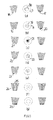
- verschiedene Probenträger nach der Erfindung mit unterschiedlichen Probenaufnahmebereichen,
- Fig. 14
- Probenträger nach der Erfindung mit unterschiedlichen Handhabungsbereichen,
- Fig. 15
- einen weiteren Probenträger nach der Erfindung zur Vorverarbeitung einer Blutprobe unter Abtrennung von Blutplasma,
- Fig. 16
- einen Probenträger nach der Erfindung mit einem als Entlüftungsund Spülkanal dienenden Durchgang,
- Fig. 17
- den Probenträger von
Fig. 16 in Verbindung mit einem Handhabungsgerät, - Fig. 18
- den Probenträger von
Fig. 16 in Verbindung mit einem gegenüber dem Handhabungsgerät vonFig. 17 modifizierten Handhabungsgerät, - Fig. 19
- eine Teilansicht eines weiteren, durch das Handhabungsgerät von
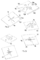
Fig. 18 manipulierbaren Probenträgers nach der Erfindung, - Fig. 20
- ein drehbares Dosierelement,
- Fig. 21
- eine zur Zusammenarbeit mit dem Dosierelement von
Fig. 20 vorgesehene Flusszelle, und - Fig. 22
- eine Anordnung aus dem Dosierelement von
Fig. 20 und der Flusszelle vonFig. 21 in verschiedenen Arbeitsstellungen des Dosierelements.
- Fig. 1
- a flow cell according to the invention with and without a sample carrier in perspective view,
- Fig. 2
- the flow cell of
Fig. 1 in perspective view from below with attached to the flow cell sample carrier, - Fig. 3
- in the flow cell of
Fig. 1 and 2 used sample carriers in perspective as well as axially cut view, - Fig. 4 and Fig. 4a
- the admission of a sample by the sample carrier of
Fig. 1 to 3 explanatory illustrations, - Fig. 5
- various sample carriers according to the invention in sectioned partial side views and in plan view from below,
- Fig. 6
- a sample carrier according to the invention with a flushing channel and a sample receiving region formed by a capillary,
- Fig. 7
- a sample carrier according to the invention with a flushing channel and a conical capillary receiving area,
- Fig. 8
- a sample carrier according to
Fig. 6 with an end constriction of the capillary, - Fig. 9 and Fig. 9a
- a sample carrier according to the invention with a flushing channel respectively opening at the ends of a cone,
- Fig. 10
- Examples of the connection of a sample carrier according to the invention with different regions of a flow cell,
- FIGS. 11 and 12
- the sample carriers of
6 and 9 in connection with a flow cell, - Fig. 13
- various sample carriers according to the invention with different sample receiving areas,
- Fig. 14
- Sample carrier according to the invention with different handling areas,
- Fig. 15
- a further sample carrier according to the invention for preprocessing a blood sample with separation of blood plasma,
- Fig. 16
- a sample carrier according to the invention with a serving as vent and flushing passage,
- Fig. 17
- the sample carrier of
Fig. 16 in connection with a handling device, - Fig. 18
- the sample carrier of
Fig. 16 in conjunction with a relative to the handling device ofFig. 17 modified handling device, - Fig. 19
- a partial view of another, by the handling device of
Fig. 18 manipulatable sample carrier according to the invention, - Fig. 20
- a rotatable dosing element,
- Fig. 21
- one for cooperation with the dosing of
Fig. 20 provided flow cell, and - Fig. 22
- an arrangement of the metering of
Fig. 20 and the flow cell ofFig. 21 in different working positions of the metering element.
Eine Flusszelle umfasst ein aus Kunststoff spritzgegossenes Substrat 1, eine Laminatfolie 2 mit Schichten aus Aluminium und Kunststoff sowie eine Abdeckfolie 3 auf der der Laminatfolie 2 abgewandten Seite des Substrats 1.A flow cell comprises a substrate 1 injection-molded from plastic, a
In dem Substrat 1 sind Kammern und Kanäle gebildet, z.B. die Kammer 4 und der Kanal 5. Auswölbungen der Laminatfolie 2 bilden Speicherräume 6.In the substrate 1, chambers and channels are formed, e.g. the chamber 4 and the
Wie
Der Probenträger 7 umfasst ein konisches Trägerelement mit einem Probenaufnahmebereich 9 an einem freien Stirnende. Das Trägerelement 8 steht vom Boden eines topfförmigen Drehgriffteils 10 mit einem Innengewinde 11, in das die Gewindevorsprünge 13 eingreifen, und mit Rippenvorsprüngen 14 vor. Wie
Bei der Zuführung flüssigen Probematerials 15 zu dem Aufnahmebereich 9 gemäß
Die durch Kapillarkräfte gebundene Blutprobenmenge bleibt im Aufnahmebereich 9 haften und wird mit Hilfe des Probenträgers 7, wie oben beschrieben, in die Kammer 4 eingebracht. Im Zuge einer durchzuführenden Analyse kommt es zu einer Abspülung der Probe von dem Probenträger.The amount of blood sample bound by capillary forces remains adhering to the receiving
Ein dem Probenträger 7 entsprechender Probenträger ist in
Weitere Möglichkeiten für die Ausbildung von Aufnahmebereichen 9 des vorangehend beschriebenen Probenträgers 7 gehen aus den
Aus
Ein in
Ein weiterer zweiteilig aufgebauter Probenträger mit einem Durchgangsloch 24 als Aufnahmebereich weist eine das Durchgangsloch an einem Ende verschließende permeable Membran 25 auf. Die Membran weist Poren solcher Größe auf, dass sie für Gas nicht aber für Flüssigkeit durchlässig sind. Die Luftdurchlässigkeit der Membran 25 erlaubt eine kapillare Befüllung des Durchgangslochs 24. Eine Ausführungsform gleicher Funktion aber ohne permable Membran 25 ist ebenfalls denkbar.Another sample carrier constructed in two parts with a through
Zum Entleeren dieses Probenträgers in einer Analyseeinrichtung wird an die durch die Membran abgedeckte Seite ein pneumatischer oder hydraulischer Druck angelegt.To empty this sample carrier in an analysis device, a pneumatic or hydraulic pressure is applied to the side covered by the membrane.
Ein weiterer zweiteiliger Probenträger geht aus
In einer Analyseeinrichtung kann die Probe durch Ausdrücken des Vlieses freigesetzt werden oder mit Hilfe einer Spülflüssigkeit herausgespült werden. Die Probe lässt sich dem Analyseprozess ferner dadurch zuführen, dass sie mit einer Lateralflowmembran in Kontakt gebracht wird, wo sie durch die Kapillarwirkung der Lateralflowmembran aus dem Vlies 26 des Probenträgers herausgesaugt wird. Dieser Prozess kann durch eine Spülflüssigkeit, welche durch die Lateralflowmembran transportiert wird, unterstützt werden.In an analysis device, the sample can be released by squeezing the nonwoven fabric or rinsed out with the aid of a rinsing liquid. The sample can also be fed to the analysis process by being brought into contact with a lateral flow membrane, where it is sucked out of the
Es wird nun auf
Durchmesser zwischen 0,5 und 2 mm liegen, wobei die Länge des Durchgangslochs 34 typischerweise 2 bis 10 mm beträgt.Diameter between 0.5 and 2 mm, wherein the length of the through hole 34 is typically 2 to 10 mm.
Durch Variation der Durchmesser bzw. des Volumens des Probenaufnahmebereichs können allein durch Austausch des Probenträgers bei gleichen äußeren Abmessungen unterschiedliche Probenvolumina effektiv in eine mikrofluidische Flusszelle eingebracht und damit die abgemessenen Mengen an die Erfordernisse unterschiedliche Analysen und/oder Proben angepasst werden.By varying the diameter or the volume of the sample receiving area, different sample volumes can be effectively introduced into a microfluidic flow cell simply by exchanging the sample carrier for the same external dimensions, and thus the measured quantities can be adapted to the requirements of different analyzes and / or samples.
Ein in
Ein in
Die Plasmaseparationsmembran 72 grenzt an einen innenseitig hydrophil beschichteten, durch eine Folie 73 abgedeckten Kanal 74, dessen Enden über je eine Engstelle 75 bzw. 76 mit einem durch ein äußeres Steckelement führenden Spülkanal 77 bzw. 78 in Verbindung stehen. In dem gezeigten Beispiel ist das Volumen des Aufnahmeraums 71 etwa 2 ½-mal so groß wie das Volumen des Kanals 74.The
In dem auf eine Flusszelle aufgesteckten Zustand des in
Dem in
The in
Gemäß
Ein dem Probenträger von
Gemäß
Bei einem in
Aus
Ein Beispiel für eine Verbindung des Probenträgers von
Kunststoffe weisen in der Regel hydrophobe, für wässrige Fluide, wie z.B. Blut, schlecht benetzbare Oberflächen auf. Für den Probenaufnahmebereich von Probenträgern sind hydrophile Oberflächen vorteilhaft, auch im Hinblick auf eine exakte Bemessung von Probenmengen.
Änderungen (hydrophil oder hydrophob) der Oberflächeneigenschaften von Kunststoffen erfolgen bekanntermaßen nasschemisch durch Aufbringen von Netzmitteln oder Tensiden und nachfolgendes Trocknen, durch Oberflächenaktivierung mittels Plasma, Beflammen oder Koronabehandlung (hydrophil), durch Oberflächenbeschichtung mittels Plasmapolymerisation, z.B. Bildung glasartiger Schichten (hydrophil oder hydrophob) oder durch Kombinationen dieser Maßnahmen. Gegebenenfalls erfolgt eine lokale Maskierung behandelter Oberflächen.Plastics generally have hydrophobic, for aqueous fluids, such as blood, poorly wettable surfaces. For the sample receiving area of sample carriers, hydrophilic surfaces are advantageous, also with regard to an exact dimensioning of sample quantities.
Changes (hydrophilic or hydrophobic) of the surface properties of plastics are known to be wet-chemically by applying wetting agents or surfactants and subsequent drying, by surface activation by plasma, flaming or corona treatment (hydrophilic), by surface coating by plasma polymerization, eg formation of glassy layers (hydrophilic or hydrophobic) or through combinations of these measures. Optionally, there is a local masking of treated surfaces.
Bei dem Ausführungsbeispiel von
Das Ausführungsbeispiel von
Bei dem Ausführungsbeispiel von
Bei dem Ausführungsbeispiel von
Während in
Bei dem Ausführungsbeispiel von
Ein weiterer, eine Blutprobe vorverarbeitender Probenträger geht aus
Bei dem Probenträger von
Nach Einfüllen einer Blutprobe in den Aufnahmeraum 79 tritt durch die Plasmaseparationsmembran 80 hindurch Plasma in den Durchgang 83, wobei dessen offenes Ende einen die Plasmaprobe dosierenden Kapillarstopp bildet.After filling a blood sample into the receiving space 79, plasma enters the
Beim Aufstecken des Probenträgers auf eine Flusszelle kann das erste Spritzteil 81 als Griffelement dienen, wobei zweckmäßig eine Abdeckkappe verwendet wird, um ggf. Kontaminationen der Umgebung durch in dem Aufnahmeraum 79 verbliebenes Blut zu verhindern. Das durch die Flusszelle zu analysierende Blutplasma kann mit Hilfe eines Vlies oder einer an die Öffnung des Durchgangs 83 angrenzenden Membran aus dem Durchgang herausgesaugt werden.When attaching the sample carrier to a flow cell, the first injection molded
Wie sich
Die in
Die Flusszelle weist ferner Spülanschlüsse 105 und 106 auf, die über einen Kanal 107 miteinander in Verbindung stehen. Auf der Platte 103 sind auf der den Kanälen 101,107 abgewandten Seite Anschläge 108 und 109 gebildet.The flow cell further has
Zur Bemessung einer Probe wird das Dosierelement mit dem Steckeransatz 94 voran in die Stecköffnung 99 der Flusszelle eingesteckt, wobei der Nutenkanal 95 durch die Folie 104 abgedeckt wird. Das Dosierelement befindet sich in der in
Zur Dosierung einer bestimmten Probenmenge wird das Dosierelement um 90° gedreht, wobei es gemäß
Die in dem Nutenkanal 95 enthaltene Dosierungsmenge einer Probe kann daher über die Spülanschlüsse 105 und 106 aus der Flusszelle ausgespült und einer weiteren Verarbeitung zugeführt werden.The metering amount of a sample contained in the
Claims (15)
gekennzeichnet durch Einrichtungen zur fluiddichten Verbindung des die Probe enthaltenden Probenträgers (7) mit einer Analyseeinrichtung.Sample carrier (7) having a region (9) for receiving a sample to be analyzed, whose volume is between 1 and 100 μl, and a region (10) for handling the sample carrier,
characterized by means for fluid-tight connection of the sample carrier (7) containing the sample with an analysis device.
dadurch gekennzeichnet,
dass die in der Analyseeinrichtung gemeinsam mit dem Probenträger (7) platzierte, zu analysierende Probe an einen Hohlraum in der Analyseeinrichtung angrenzt, insbesondere an einen Hohlraum (4,41,44,45,46,52,54) in einer Flusszelle, z.B. an einen Hohlraum in Form eines Transportkanals (45,46,52), eine Kammer (4,41,44), insbesondere Mischkammer (41) oder/und an eine die Probe aussagende Membran.Sample carrier according to claim 1,
characterized,
in that the sample to be analyzed placed in the analysis device together with the sample carrier (7) adjoins a cavity in the analysis device, in particular to a cavity (4, 41, 44, 45, 46, 52, 54) in a flow cell, eg a cavity in the form of a transport channel (45, 46, 52), a chamber (4, 41, 44), in particular a mixing chamber (41) or / and a membrane expressing the sample.
dadurch gekennzeichnet,
dass die gemeinsam mit dem Probenträger (7) in der Analyseeinrichtung platzierte Probe durch eine Fluidströmung von dem Aufnahmebereich (9) ablösbar ist, wobei die Fluidströmung z.B. durch Entleerung eines in die Analyseeinrichtung integrierten oder fluiddicht mit der Analyseeinrichtung verbundenen Reagenzspeichers erzeugbar ist.Sample carrier according to claim 1 or 2,
characterized,
in that the sample placed in the analysis device together with the sample carrier (7) can be detached from the receiving region (9) by a fluid flow, wherein the fluid flow can be generated, for example, by emptying a reagent reservoir integrated into the analysis device or fluid-tightly connected to the analysis device.
dadurch gekennzeichnet,
dass der Probenträger Einrichtungen zur Vorverarbeitung dem Probenträger zugeführten Probenmaterials zu der zu analysierenden Probe aufweist, wobei die Vorverarbeitungseinrichtungen vorzugsweise Mittel zur Dosierung, Reagenzmittel (62) oder/und Trennmittel (72;80), insbesondere zur Abtrennung von Blutplasma, umfassen.Sample carrier according to one of claims 1 to 3,
characterized,
in that the sample carrier comprises means for preprocessing sample material supplied to the sample carrier to the sample to be analyzed, the preprocessing means preferably comprising means for metering, reagent (62) and / or separating means (72; 80), in particular for separating blood plasma.
dadurch gekennzeichnet,
dass der Probenträger Einrichtungen zum Abtransport der zu analysierenden Probe von dem Probenträger aufweist, insbesondere einen Spülkanal (77,78;86).Sample carrier according to one of claims 1 to 4,
characterized,
in that the sample carrier has means for removing the sample to be analyzed from the sample carrier, in particular a flushing channel (77, 78, 86).
dadurch gekennzeichnet,
dass der Probenträger (7) fluiddicht an einer in den Hohlraum mündenden Öffnung platzierbar, insbesondere in die Öffnung (12) einsetzbar, ist.Sample carrier according to one of claims 2 to 5,
characterized,
is used that the sample carrier (7) placeable in fluid-tight at one opening into the cavity opening, particularly in the opening (12).
dadurch gekennzeichnet,
dass der Probenträger(7) pfropfenartig die Öffnung (12) verschließt und insbesondere durch die Öffnung (12) ein Presssitz für vorzugsweise ein konisches Trägerelement (8) des Probenträgers (7) in der Art eines LUER-Verschlusses gebildet ist.Sample carrier according to claim 6,
characterized,
in that the sample carrier (7) closes off the opening (12) in the manner of a plug, and in particular through the opening (12) an interference fit for preferably a conical carrier element (8) of the sample carrier (7) is formed in the manner of a LUER closure.
dadurch gekennzeichnet,
dass der Aufnahmebereich (9) Mittel zur dosierten Aufnahme der Probe umfasst.Sample carrier according to one of claims 4 to 7,
characterized,
in that the receiving region (9) comprises means for the metered admission of the sample.
dadurch gekennzeichnet,
dass die Mittel zur dosierten Aufnahme der Probe räumliche Begrenzungen des Probenaufnahmebereichs (9) umfassen.Sample carrier according to claim 8,
characterized,
in that the means for metering in the sample comprise spatial boundaries of the sample receiving area (9).
dadurch gekennzeichnet,
dass die Mittel zur dosierten Aufnahme der Probe wenigstens eine Oberflächenbeschichtung zur Steuerung der Benetzbarkeit des Aufnahmebereichs (9) oder unterschiedlich benetzbare, an den Probenaufnahmebereich (9) angrenzende Kunststoffmaterialien umfassen.Sample carrier according to claim 8 or 9,
characterized,
in that the means for metering in the sample comprise at least one surface coating for controlling the wettability of the receiving area (9) or differently wettable plastic materials adjacent to the sample receiving area (9).
dadurch gekennzeichnet,
dass der Handhabungsbereich (10,64,65,68) eine manuelle Handhabung des Probenträgers (7)ohne Berührung der Probe erlaubt.Sample carrier according to one of claims 1 to 10,
characterized,
that the handle portion (10,64,65,68) has a manual handling of the sample carrier (7) without touching the sample allowed.
dadurch gekennzeichnet,
dass der die Öffnung pfropfenartig verschließende Probenträger unter fluiddichtem Verschluss der Öffnung in der Öffnung drehbar ist.Sample carrier according to one of claims 7 to 11,
characterized,
in that the sample holder which closes off the opening in a plug-like manner is rotatable under fluid-tight closure of the opening in the opening.
dadurch gekennzeichnet,
dass eine die Entnahme des mit der Analyseeinrichtung verbundenen Probenträgers (7) verhindernde Verschlusseinrichtung vorgesehen ist.Sample carrier according to one of claims 1 to 12,
characterized,
that a removal of the device connected to the analysis sample carrier (7) preventing closure device is provided.
dadurch gekennzeichnet,
dass der Aufnahmebereich ein Trockenreagenz (62) für eine erste, das Probenmaterial vorverarbeitende Reaktion mit der Probe, umfasst.Sample carrier according to one of claims 4 to 13,
characterized,
in that the receiving area comprises a dry reagent (62) for a first sample material preprocessing reaction with the sample.
Priority Applications (3)
| Application Number | Priority Date | Filing Date | Title |
|---|---|---|---|
| EP15173174.2A EP3108962A1 (en) | 2015-06-22 | 2015-06-22 | Sample carrier |
| PCT/EP2016/060498 WO2016206854A1 (en) | 2015-06-22 | 2016-05-11 | Sample carrier |
| US15/738,421 US11045802B2 (en) | 2015-06-22 | 2016-05-11 | Sample carrier |
Applications Claiming Priority (1)
| Application Number | Priority Date | Filing Date | Title |
|---|---|---|---|
| EP15173174.2A EP3108962A1 (en) | 2015-06-22 | 2015-06-22 | Sample carrier |
Publications (1)
| Publication Number | Publication Date |
|---|---|
| EP3108962A1 true EP3108962A1 (en) | 2016-12-28 |
Family
ID=53496441
Family Applications (1)
| Application Number | Title | Priority Date | Filing Date |
|---|---|---|---|
| EP15173174.2A Pending EP3108962A1 (en) | 2015-06-22 | 2015-06-22 | Sample carrier |
Country Status (3)
| Country | Link |
|---|---|
| US (1) | US11045802B2 (en) |
| EP (1) | EP3108962A1 (en) |
| WO (1) | WO2016206854A1 (en) |
Cited By (3)
| Publication number | Priority date | Publication date | Assignee | Title |
|---|---|---|---|---|
| WO2019142141A1 (en) * | 2018-01-18 | 2019-07-25 | Holger Engel | Dry chemistry container |
| EP3747542A1 (en) | 2019-06-07 | 2020-12-09 | Thinxxs Microtechnology Ag | Transfer system for samples, in particular samples to be analysed |
| US11426725B2 (en) * | 2016-06-30 | 2022-08-30 | Thinxxs Microtechnology Gmbh | Flow cell having a reagent reservoir |
Families Citing this family (2)
| Publication number | Priority date | Publication date | Assignee | Title |
|---|---|---|---|---|
| EP3342485B1 (en) * | 2017-01-02 | 2020-07-08 | Thinxxs Microtechnology Ag | Holder for reagent elements |
| JP7164552B2 (en) * | 2018-11-30 | 2022-11-01 | 積水化学工業株式会社 | Measuring tool and liquid transfer method |
Citations (5)
| Publication number | Priority date | Publication date | Assignee | Title |
|---|---|---|---|---|
| DE9417612U1 (en) * | 1994-11-03 | 1995-01-05 | Kloth Bernd | Sampling device |
| WO2000074853A1 (en) | 1999-06-04 | 2000-12-14 | Axis-Shield Poc As | Container, closure and method of mixing two materials |
| US20040156746A1 (en) * | 2001-05-10 | 2004-08-12 | Larsen Ulrik Darling | Device for sampling small and precise volumes of liquid |
| WO2005094681A1 (en) | 2004-03-26 | 2005-10-13 | Sarstedt Ag & Co. | Device for collecting capillary blood |
| EP2821138A1 (en) * | 2013-07-05 | 2015-01-07 | Thinxxs Microtechnology Ag | Flow cell with integrated dry substance |
Family Cites Families (14)
| Publication number | Priority date | Publication date | Assignee | Title |
|---|---|---|---|---|
| US5257984A (en) * | 1991-10-02 | 1993-11-02 | Norfolk Scientific, Inc. | Blood collector |
| US6319209B1 (en) * | 1999-08-23 | 2001-11-20 | European Institute Of Science | Disposable test vial with sample delivery device for dispensing sample into a reagent |
| US7863035B2 (en) * | 2007-02-15 | 2011-01-04 | Osmetech Technology Inc. | Fluidics devices |
| KR101629046B1 (en) * | 2008-08-21 | 2016-06-09 | 디엔에이 제노텍 인코퍼레이티드 | Sample receiving device |
| DE102008054313B4 (en) * | 2008-11-03 | 2012-12-13 | Zenteris Gmbh | Cartridge and apparatus for assaying biological samples with temperature-controlled biological responses |
| GB2473425A (en) * | 2009-09-03 | 2011-03-16 | Vivacta Ltd | Fluid Sample Collection Device |
| CA2869732C (en) * | 2012-04-12 | 2018-04-03 | Kristin Weidemaier | Methods, systems, and devices for detecting and identifying microorganisms in microbiological culture samples |
| PL2676606T3 (en) * | 2012-06-20 | 2017-10-31 | Fabpulous B V | Quick test device and method |
| US9592507B2 (en) * | 2012-06-22 | 2017-03-14 | Abbott Point Of Care Inc. | Integrated cartridge housings for sample analysis |
| US9557320B2 (en) * | 2013-03-15 | 2017-01-31 | University Of Calgary | Ported parallel plate flow chamber and methods for use thereof |
| US20140295441A1 (en) | 2013-03-27 | 2014-10-02 | Zygem Corporation Ltd. | Cartridge interface module |
| JP6401300B2 (en) * | 2014-05-21 | 2018-10-10 | オリオン ダイアグノスティカ オーワイ | Sampling and analysis kit, sample holder and method |
| EP2982436B1 (en) | 2014-08-04 | 2020-09-09 | Skyla Corporation Hsinchu Science Park Branch | Testing module for testing a sample |
| CN106999929A (en) | 2014-09-11 | 2017-08-01 | 克忧公司 | For detecting the system and method with analyte quantification |
-
2015
- 2015-06-22 EP EP15173174.2A patent/EP3108962A1/en active Pending
-
2016
- 2016-05-11 WO PCT/EP2016/060498 patent/WO2016206854A1/en active Application Filing
- 2016-05-11 US US15/738,421 patent/US11045802B2/en active Active
Patent Citations (5)
| Publication number | Priority date | Publication date | Assignee | Title |
|---|---|---|---|---|
| DE9417612U1 (en) * | 1994-11-03 | 1995-01-05 | Kloth Bernd | Sampling device |
| WO2000074853A1 (en) | 1999-06-04 | 2000-12-14 | Axis-Shield Poc As | Container, closure and method of mixing two materials |
| US20040156746A1 (en) * | 2001-05-10 | 2004-08-12 | Larsen Ulrik Darling | Device for sampling small and precise volumes of liquid |
| WO2005094681A1 (en) | 2004-03-26 | 2005-10-13 | Sarstedt Ag & Co. | Device for collecting capillary blood |
| EP2821138A1 (en) * | 2013-07-05 | 2015-01-07 | Thinxxs Microtechnology Ag | Flow cell with integrated dry substance |
Cited By (4)
| Publication number | Priority date | Publication date | Assignee | Title |
|---|---|---|---|---|
| US11426725B2 (en) * | 2016-06-30 | 2022-08-30 | Thinxxs Microtechnology Gmbh | Flow cell having a reagent reservoir |
| WO2019142141A1 (en) * | 2018-01-18 | 2019-07-25 | Holger Engel | Dry chemistry container |
| EP3747542A1 (en) | 2019-06-07 | 2020-12-09 | Thinxxs Microtechnology Ag | Transfer system for samples, in particular samples to be analysed |
| WO2020244864A1 (en) | 2019-06-07 | 2020-12-10 | Thinxxs Microtechnology Ag | Transfer system for samples, more particularly samples to be analysed |
Also Published As
| Publication number | Publication date |
|---|---|
| US20180185841A1 (en) | 2018-07-05 |
| WO2016206854A1 (en) | 2016-12-29 |
| US11045802B2 (en) | 2021-06-29 |
Similar Documents
| Publication | Publication Date | Title |
|---|---|---|
| WO2016206854A1 (en) | Sample carrier | |
| EP3164212B1 (en) | Reagent reservoir for fluids | |
| EP2632590B1 (en) | Microfluidic test carrier for dividing a liquid quantity into subquantities | |
| EP3541516B1 (en) | Device for receiving, dispensing, and moving liquids | |
| EP2413138B1 (en) | Device and method for separating components of a liquid sample | |
| EP2654955B1 (en) | Method for mixing at least one sample solution with reagents | |
| DE102013203293B4 (en) | Apparatus and method for conducting a liquid through a first or second outlet channel | |
| EP2428272B1 (en) | Method for hydrophobic coating of pipette tips | |
| DE10238266A1 (en) | Microfluidic system | |
| WO2011067241A1 (en) | Microfluidic element for analyzing a liquid sample | |
| EP1474235A1 (en) | Sample preparation device and test device set based thereon | |
| EP3263215B1 (en) | Device with a flow cell with reagent storage | |
| DE102018111822B4 (en) | Fluidic system for receiving, dispensing and moving liquids, method for processing fluids in a fluidic system | |
| EP1541986A1 (en) | Sampling device for examining a fluid sample | |
| DE102011079698B4 (en) | Microfluidic device having a chamber for storing a liquid | |
| EP2992324B1 (en) | Sample dispenser for an analytical device | |
| EP1533035A1 (en) | Sample carrier | |
| EP2834006A1 (en) | Chamber component for a reagent vessel, and use thereof | |
| DE102016015944B3 (en) | Microfluidic system for the intake, delivery and movement of fluids | |
| DE102016222028A1 (en) | Microfluidic container | |
| EP3747542A1 (en) | Transfer system for samples, in particular samples to be analysed | |
| WO2024023229A1 (en) | Sample-receiving device | |
| EP2834005B1 (en) | Capillary device for reagent container and its use | |
| DE102019007512A1 (en) | Microfluidic device for holding liquids and associated process | |
| EP2759343A1 (en) | Unit for storing a fluid and method for producing a unit for storing a fluid |
Legal Events
| Date | Code | Title | Description |
|---|---|---|---|
| PUAI | Public reference made under article 153(3) epc to a published international application that has entered the european phase |
Free format text: ORIGINAL CODE: 0009012 |
|
| STAA | Information on the status of an ep patent application or granted ep patent |
Free format text: STATUS: THE APPLICATION HAS BEEN PUBLISHED |
|
| AK | Designated contracting states |
Kind code of ref document: A1 Designated state(s): AL AT BE BG CH CY CZ DE DK EE ES FI FR GB GR HR HU IE IS IT LI LT LU LV MC MK MT NL NO PL PT RO RS SE SI SK SM TR |
|
| AX | Request for extension of the european patent |
Extension state: BA ME |
|
| STAA | Information on the status of an ep patent application or granted ep patent |
Free format text: STATUS: REQUEST FOR EXAMINATION WAS MADE |
|
| 17P | Request for examination filed |
Effective date: 20170628 |
|
| RBV | Designated contracting states (corrected) |
Designated state(s): AL AT BE BG CH CY CZ DE DK EE ES FI FR GB GR HR HU IE IS IT LI LT LU LV MC MK MT NL NO PL PT RO RS SE SI SK SM TR |
|
| STAA | Information on the status of an ep patent application or granted ep patent |
Free format text: STATUS: EXAMINATION IS IN PROGRESS |
|
| 17Q | First examination report despatched |
Effective date: 20180322 |
|
| STAA | Information on the status of an ep patent application or granted ep patent |
Free format text: STATUS: EXAMINATION IS IN PROGRESS |
|
| STAA | Information on the status of an ep patent application or granted ep patent |
Free format text: STATUS: EXAMINATION IS IN PROGRESS |
|
| RAP3 | Party data changed (applicant data changed or rights of an application transferred) |
Owner name: THINXXS MICROTECHNOLOGY GMBH |