EP3108962A1 - Porte échantillons - Google Patents
Porte échantillons Download PDFInfo
- Publication number
- EP3108962A1 EP3108962A1 EP15173174.2A EP15173174A EP3108962A1 EP 3108962 A1 EP3108962 A1 EP 3108962A1 EP 15173174 A EP15173174 A EP 15173174A EP 3108962 A1 EP3108962 A1 EP 3108962A1
- Authority
- EP
- European Patent Office
- Prior art keywords
- sample
- sample carrier
- carrier according
- opening
- carrier
- Prior art date
- Legal status (The legal status is an assumption and is not a legal conclusion. Google has not performed a legal analysis and makes no representation as to the accuracy of the status listed.)
- Pending
Links
- 239000000523 sample Substances 0.000 claims description 296
- 210000004027 cell Anatomy 0.000 claims description 60
- 210000002381 plasma Anatomy 0.000 claims description 17
- 238000011010 flushing procedure Methods 0.000 claims description 16
- 239000012528 membrane Substances 0.000 claims description 16
- 239000003153 chemical reaction reagent Substances 0.000 claims description 11
- 239000004033 plastic Substances 0.000 claims description 11
- 229920003023 plastic Polymers 0.000 claims description 11
- 239000012530 fluid Substances 0.000 claims description 10
- 238000007781 pre-processing Methods 0.000 claims description 9
- 238000002156 mixing Methods 0.000 claims description 8
- 238000000576 coating method Methods 0.000 claims description 6
- 239000000463 material Substances 0.000 claims description 6
- 239000011248 coating agent Substances 0.000 claims description 5
- 238000006243 chemical reaction Methods 0.000 claims description 2
- 210000004369 blood Anatomy 0.000 description 18
- 239000008280 blood Substances 0.000 description 18
- 239000007788 liquid Substances 0.000 description 15
- 230000032258 transport Effects 0.000 description 8
- 238000011049 filling Methods 0.000 description 7
- 238000000926 separation method Methods 0.000 description 7
- 239000000969 carrier Substances 0.000 description 6
- 239000010408 film Substances 0.000 description 5
- 238000000034 method Methods 0.000 description 5
- 230000008569 process Effects 0.000 description 5
- 238000012545 processing Methods 0.000 description 5
- 230000015572 biosynthetic process Effects 0.000 description 4
- 230000002209 hydrophobic effect Effects 0.000 description 4
- 238000002347 injection Methods 0.000 description 4
- 239000007924 injection Substances 0.000 description 4
- 238000010926 purge Methods 0.000 description 4
- 239000012472 biological sample Substances 0.000 description 3
- 230000006870 function Effects 0.000 description 3
- 239000005001 laminate film Substances 0.000 description 3
- 239000000758 substrate Substances 0.000 description 3
- 238000009736 wetting Methods 0.000 description 3
- 239000012470 diluted sample Substances 0.000 description 2
- 238000006073 displacement reaction Methods 0.000 description 2
- 238000001746 injection moulding Methods 0.000 description 2
- 229920003229 poly(methyl methacrylate) Polymers 0.000 description 2
- 239000004926 polymethyl methacrylate Substances 0.000 description 2
- 238000013022 venting Methods 0.000 description 2
- XLYOFNOQVPJJNP-UHFFFAOYSA-N water Substances O XLYOFNOQVPJJNP-UHFFFAOYSA-N 0.000 description 2
- KRKNYBCHXYNGOX-UHFFFAOYSA-K Citrate Chemical compound [O-]C(=O)CC(O)(CC([O-])=O)C([O-])=O KRKNYBCHXYNGOX-UHFFFAOYSA-K 0.000 description 1
- 206010053567 Coagulopathies Diseases 0.000 description 1
- HTTJABKRGRZYRN-UHFFFAOYSA-N Heparin Chemical compound OC1C(NC(=O)C)C(O)OC(COS(O)(=O)=O)C1OC1C(OS(O)(=O)=O)C(O)C(OC2C(C(OS(O)(=O)=O)C(OC3C(C(O)C(O)C(O3)C(O)=O)OS(O)(=O)=O)C(CO)O2)NS(O)(=O)=O)C(C(O)=O)O1 HTTJABKRGRZYRN-UHFFFAOYSA-N 0.000 description 1
- 239000002250 absorbent Substances 0.000 description 1
- 230000002745 absorbent Effects 0.000 description 1
- 230000009471 action Effects 0.000 description 1
- 230000004913 activation Effects 0.000 description 1
- 150000001336 alkenes Chemical class 0.000 description 1
- XAGFODPZIPBFFR-UHFFFAOYSA-N aluminium Chemical compound [Al] XAGFODPZIPBFFR-UHFFFAOYSA-N 0.000 description 1
- 229910052782 aluminium Inorganic materials 0.000 description 1
- 230000010100 anticoagulation Effects 0.000 description 1
- 238000013459 approach Methods 0.000 description 1
- 210000001124 body fluid Anatomy 0.000 description 1
- 239000010839 body fluid Substances 0.000 description 1
- 238000005119 centrifugation Methods 0.000 description 1
- 239000003795 chemical substances by application Substances 0.000 description 1
- 230000035602 clotting Effects 0.000 description 1
- 230000001143 conditioned effect Effects 0.000 description 1
- 238000011109 contamination Methods 0.000 description 1
- 238000003851 corona treatment Methods 0.000 description 1
- 239000013039 cover film Substances 0.000 description 1
- 238000013461 design Methods 0.000 description 1
- 238000007865 diluting Methods 0.000 description 1
- 238000007598 dipping method Methods 0.000 description 1
- 238000001035 drying Methods 0.000 description 1
- 230000007613 environmental effect Effects 0.000 description 1
- 239000011888 foil Substances 0.000 description 1
- 229960002897 heparin Drugs 0.000 description 1
- 229920000669 heparin Polymers 0.000 description 1
- 230000005660 hydrophilic surface Effects 0.000 description 1
- 230000005661 hydrophobic surface Effects 0.000 description 1
- 230000002934 lysing effect Effects 0.000 description 1
- 239000012139 lysis buffer Substances 0.000 description 1
- 230000014759 maintenance of location Effects 0.000 description 1
- 230000000873 masking effect Effects 0.000 description 1
- 230000004048 modification Effects 0.000 description 1
- 238000012986 modification Methods 0.000 description 1
- 239000004745 nonwoven fabric Substances 0.000 description 1
- JRZJOMJEPLMPRA-UHFFFAOYSA-N olefin Natural products CCCCCCCC=C JRZJOMJEPLMPRA-UHFFFAOYSA-N 0.000 description 1
- 230000035699 permeability Effects 0.000 description 1
- 238000009832 plasma treatment Methods 0.000 description 1
- 238000006116 polymerization reaction Methods 0.000 description 1
- 239000011148 porous material Substances 0.000 description 1
- 210000003296 saliva Anatomy 0.000 description 1
- 238000007789 sealing Methods 0.000 description 1
- 239000000126 substance Substances 0.000 description 1
- 239000013589 supplement Substances 0.000 description 1
- 238000004381 surface treatment Methods 0.000 description 1
- 239000004094 surface-active agent Substances 0.000 description 1
- 210000002700 urine Anatomy 0.000 description 1
- 239000000080 wetting agent Substances 0.000 description 1
Images


Classifications
-
- B—PERFORMING OPERATIONS; TRANSPORTING
- B01—PHYSICAL OR CHEMICAL PROCESSES OR APPARATUS IN GENERAL
- B01L—CHEMICAL OR PHYSICAL LABORATORY APPARATUS FOR GENERAL USE
- B01L3/00—Containers or dishes for laboratory use, e.g. laboratory glassware; Droppers
- B01L3/50—Containers for the purpose of retaining a material to be analysed, e.g. test tubes
- B01L3/502—Containers for the purpose of retaining a material to be analysed, e.g. test tubes with fluid transport, e.g. in multi-compartment structures
- B01L3/5027—Containers for the purpose of retaining a material to be analysed, e.g. test tubes with fluid transport, e.g. in multi-compartment structures by integrated microfluidic structures, i.e. dimensions of channels and chambers are such that surface tension forces are important, e.g. lab-on-a-chip
- B01L3/502715—Containers for the purpose of retaining a material to be analysed, e.g. test tubes with fluid transport, e.g. in multi-compartment structures by integrated microfluidic structures, i.e. dimensions of channels and chambers are such that surface tension forces are important, e.g. lab-on-a-chip characterised by interfacing components, e.g. fluidic, electrical, optical or mechanical interfaces
-
- A—HUMAN NECESSITIES
- A61—MEDICAL OR VETERINARY SCIENCE; HYGIENE
- A61J—CONTAINERS SPECIALLY ADAPTED FOR MEDICAL OR PHARMACEUTICAL PURPOSES; DEVICES OR METHODS SPECIALLY ADAPTED FOR BRINGING PHARMACEUTICAL PRODUCTS INTO PARTICULAR PHYSICAL OR ADMINISTERING FORMS; DEVICES FOR ADMINISTERING FOOD OR MEDICINES ORALLY; BABY COMFORTERS; DEVICES FOR RECEIVING SPITTLE
- A61J1/00—Containers specially adapted for medical or pharmaceutical purposes
- A61J1/05—Containers specially adapted for medical or pharmaceutical purposes for collecting, storing or administering blood, plasma or medical fluids ; Infusion or perfusion containers
-
- B—PERFORMING OPERATIONS; TRANSPORTING
- B01—PHYSICAL OR CHEMICAL PROCESSES OR APPARATUS IN GENERAL
- B01L—CHEMICAL OR PHYSICAL LABORATORY APPARATUS FOR GENERAL USE
- B01L2200/00—Solutions for specific problems relating to chemical or physical laboratory apparatus
- B01L2200/02—Adapting objects or devices to another
- B01L2200/026—Fluid interfacing between devices or objects, e.g. connectors, inlet details
- B01L2200/027—Fluid interfacing between devices or objects, e.g. connectors, inlet details for microfluidic devices
-
- B—PERFORMING OPERATIONS; TRANSPORTING
- B01—PHYSICAL OR CHEMICAL PROCESSES OR APPARATUS IN GENERAL
- B01L—CHEMICAL OR PHYSICAL LABORATORY APPARATUS FOR GENERAL USE
- B01L2200/00—Solutions for specific problems relating to chemical or physical laboratory apparatus
- B01L2200/16—Reagents, handling or storing thereof
-
- B—PERFORMING OPERATIONS; TRANSPORTING
- B01—PHYSICAL OR CHEMICAL PROCESSES OR APPARATUS IN GENERAL
- B01L—CHEMICAL OR PHYSICAL LABORATORY APPARATUS FOR GENERAL USE
- B01L2300/00—Additional constructional details
- B01L2300/04—Closures and closing means
- B01L2300/046—Function or devices integrated in the closure
-
- B—PERFORMING OPERATIONS; TRANSPORTING
- B01—PHYSICAL OR CHEMICAL PROCESSES OR APPARATUS IN GENERAL
- B01L—CHEMICAL OR PHYSICAL LABORATORY APPARATUS FOR GENERAL USE
- B01L2300/00—Additional constructional details
- B01L2300/06—Auxiliary integrated devices, integrated components
- B01L2300/0681—Filter
-
- B—PERFORMING OPERATIONS; TRANSPORTING
- B01—PHYSICAL OR CHEMICAL PROCESSES OR APPARATUS IN GENERAL
- B01L—CHEMICAL OR PHYSICAL LABORATORY APPARATUS FOR GENERAL USE
- B01L2300/00—Additional constructional details
- B01L2300/06—Auxiliary integrated devices, integrated components
- B01L2300/069—Absorbents; Gels to retain a fluid
-
- B—PERFORMING OPERATIONS; TRANSPORTING
- B01—PHYSICAL OR CHEMICAL PROCESSES OR APPARATUS IN GENERAL
- B01L—CHEMICAL OR PHYSICAL LABORATORY APPARATUS FOR GENERAL USE
- B01L2300/00—Additional constructional details
- B01L2300/08—Geometry, shape and general structure
- B01L2300/0809—Geometry, shape and general structure rectangular shaped
- B01L2300/0816—Cards, e.g. flat sample carriers usually with flow in two horizontal directions
-
- B—PERFORMING OPERATIONS; TRANSPORTING
- B01—PHYSICAL OR CHEMICAL PROCESSES OR APPARATUS IN GENERAL
- B01L—CHEMICAL OR PHYSICAL LABORATORY APPARATUS FOR GENERAL USE
- B01L2300/00—Additional constructional details
- B01L2300/16—Surface properties and coatings
- B01L2300/161—Control and use of surface tension forces, e.g. hydrophobic, hydrophilic
-
- B—PERFORMING OPERATIONS; TRANSPORTING
- B01—PHYSICAL OR CHEMICAL PROCESSES OR APPARATUS IN GENERAL
- B01L—CHEMICAL OR PHYSICAL LABORATORY APPARATUS FOR GENERAL USE
- B01L2400/00—Moving or stopping fluids
- B01L2400/04—Moving fluids with specific forces or mechanical means
- B01L2400/0403—Moving fluids with specific forces or mechanical means specific forces
- B01L2400/0406—Moving fluids with specific forces or mechanical means specific forces capillary forces
-
- B—PERFORMING OPERATIONS; TRANSPORTING
- B01—PHYSICAL OR CHEMICAL PROCESSES OR APPARATUS IN GENERAL
- B01L—CHEMICAL OR PHYSICAL LABORATORY APPARATUS FOR GENERAL USE
- B01L3/00—Containers or dishes for laboratory use, e.g. laboratory glassware; Droppers
- B01L3/50—Containers for the purpose of retaining a material to be analysed, e.g. test tubes
- B01L3/502—Containers for the purpose of retaining a material to be analysed, e.g. test tubes with fluid transport, e.g. in multi-compartment structures
- B01L3/5027—Containers for the purpose of retaining a material to be analysed, e.g. test tubes with fluid transport, e.g. in multi-compartment structures by integrated microfluidic structures, i.e. dimensions of channels and chambers are such that surface tension forces are important, e.g. lab-on-a-chip
- B01L3/502707—Containers for the purpose of retaining a material to be analysed, e.g. test tubes with fluid transport, e.g. in multi-compartment structures by integrated microfluidic structures, i.e. dimensions of channels and chambers are such that surface tension forces are important, e.g. lab-on-a-chip characterised by the manufacture of the container or its components
Definitions
- the invention relates to a sample carrier having a region for receiving a sample to be analyzed, in particular a biological sample whose volume is between 1 and 100 ⁇ l, and having an area for handling the sample carrier.
- the invention further relates to an analysis device, in particular a flow cell, with such a sample carrier.
- a sample carrier for receiving a biological sample with a sample metered receiving capillary.
- the capillary is adjoined by a cylinder space in which a piston for ejecting the sample from the capillary can be moved via an air cushion.
- an opening channel provides venting of the cylinder. With the displacement of the piston in the cylinder, this opening channel closes.
- the WO 00/74853 A1 describes a sample carrier combined with a closure element for a container.
- a biological sample passes into the container interior, where it is shielded from the outside environment and comes into contact with a diluting liquid.
- the diluted sample is then removed from the container and sent for analysis.
- the present invention provides a new sample carrier of the type mentioned above, which is characterized by means for fluid-tight connection of the sample carrier containing the sample together with the sample in an analysis device.
- a sample to be analyzed is supplied to the analysis process by the sample carrier according to the invention directly by the shortest route.
- the sample input e.g. the input of a body fluid such as blood, urine and saliva, a food sample or an environmental sample, in particular water sample, in a flow cell is no longer an input port to close after entering, but the sample input in the analysis process is the fluid-tight placement of the sample amount possibly already metered carrying sample holder completed. Sample dosing within the flow cell can be omitted.
- the sample placed in the analysis device together with the sample carrier adjoins a cavity in the analysis device involved in the analysis, in particular in a flow cell, and the sample carrier closes the cavity outward in a fluid-tight manner.
- the sample carrier e.g. the flow cell is automatically closed by the sample carrier itself.
- the cavity may also be filled with a fluid-receiving material, such as e.g. a nonwoven or a porous membrane may be filled.
- the above-mentioned cavity may be e.g. to act a transport channel or a chamber, in particular mixing chamber.
- the sample placed together with the sample carrier in the analysis device can be detached from the sample receiving region by a fluid flow.
- the fluid may be both a rinsing liquid and a gas, in particular compressed air.
- the above-mentioned fluid flow may e.g. can be produced by emptying a reagent storage device integrated into the analyzer or fluid-tightly connected to the analyzer, e.g. a deformation of the storage space of the reagent storage is carried out by actuation.
- the sample carrier itself may have means for removing the sample to be analyzed from the sample carrier, for example a rinsing channel extending through the sample carrier and carrying a rinsing liquid or a rinsing gas.
- the sample carrier has facilities for preprocessing supplied sample material. In the course of preprocessing, the sample to be analyzed is formed from this.
- the pre-processing devices preferably comprise means for metering the sample material, reagent or / and release agent, in particular for the separation of blood plasma.
- the sample carrier fluid-tight covers an opening into the cavity opening, in particular it can be inserted into the opening and preferably closes the opening in a plug-like manner.
- an interference fit for the sample carrier is formed through the opening, the sample carrier in particular having a cone corresponding to a Luer closure.
- the sample holder which closes the opening in a plug-like manner can be rotatable in the opening under fluid-tight closure.
- sample carrier preferably in one piece, is produced as a plastic injection-molded part, with possibly several receiving regions for a sample being formed on a sample carrier.
- the receiving area itself has means for the metered recording of the sample, wherein in addition to geometric limitations of the sample receiving area especially surface coatings and / or locally used plastic materials for controlling the wettability of the receiving area into consideration, in particular such that the sample receiving area is selectively wetted with sample material ,
- the handling area allows manual handling of the sample carrier without touching the sample.
- the handling region may be a handle which, after placement of the sample carrier in the analysis device, can be broken off from the remaining sample carrier at a predetermined breaking point.
- the sample carrier may have a closure device preventing the removal of the placed sample carrier from the analysis device, such as e.g. a snap closure or the like.
- the receiving area of the sample carrier comprises a dry reagent, optionally for a first reaction with the sample.
- a flow cell comprises a substrate 1 injection-molded from plastic, a laminate film 2 with layers of aluminum and plastic, and a cover film 3 on the side of the substrate 1 facing away from the laminate film 2.
- chambers and channels are formed, e.g. the chamber 4 and the channel 5. bulges of the laminate film 2 form memory spaces. 6
- a sample carrier 7 is arranged on a chamber wall 16 forming the chamber 4, which is screwed to a nozzle 12 projecting from the chamber wall 16, threaded projections 13 having.
- the sample carrier 7 comprises a conical carrier element with a sample receiving region 9 at a free front end.
- the carrier element 8 protrudes from the bottom of a cup-shaped rotary handle part 10 with an internal thread 11 into which the thread projections 13 engage, and with rib projections 14.
- the sample receiving portion 9 of the screwed with the nozzle 12 sample carrier 7 is in the chamber 4 inside.
- the sample receiving region 9 comprises a groove 18 which is open on three sides and in which a sample quantity held by capillary forces remains.
- the user holding the sample carrier 7 on the rotary handle part 10 does not come into contact with the sample quantity if he introduces the sample quantity by screwing the sample carrier 7 with the nozzle 12 into the flow cell.
- screwing the conical support member 8 forms with the conical inner surface of the nozzle 12 a fluid-tight press fit.
- a coating which determines the wettability of the groove walls in the receiving area 9 provides for the reproducible dimensioning of a sample volume.
- blood or other aqueous samples as fluid sample material fill the groove capillary, whereby a certain blood sample quantity is measured on account of the hydrophilic wetting properties.
- the amount of blood sample bound by capillary forces remains adhering to the receiving region 9 and is introduced into the chamber 4 with the aid of the sample carrier 7, as described above.
- a rinsing of the sample from the sample carrier In the course of an analysis to be carried out, a rinsing of the sample from the sample carrier.
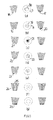
- a sample carrier 7 corresponding sample carrier is in Fig. 5a shown.
- the open on three sides groove 18 receives a defined amount of sample 17.
- Fig. 5b shows a receiving area in the form of a pocket-shaped recess 19 in the end face of the conical carrier element 8. Through the recess 19, a sample quantity 20 is reproducibly formed in the form of drops.
- Fig. 5c concerns how Fig. 5b a receiving area in the form of a round depression.
- the preferably hydrophilized depression has a wetting surface increasing microstructure, for example, from the bottom of the recess projecting columns 21.
- a grid of the column array is between 10 and 500 .mu.m, preferably between 20 and 200 microns. The microstructuring leads to improved wetting properties and better control of droplet formation and thus further improved reproducibility of the sample quantities.
- Fig. 5d shows a receiving area, which is formed by a schlöngelten open at its ends groove channel 22 in the end wall of the conical support member.
- the cross section of this channel is in the example shown at 0.2 x 0.2 mm 2 , preferably between 0.1 and 0.5 mm 2 .
- the smaller cross-sectional dimensions of the optionally hydrophilically modified channel allow better control of the wettability and thus the reproducibility of the measured amount of sample.
- Fig. 5e shown embodiment is similar to the example of Fig. 5d except for one arranged on the end face of the conical support member cover sheet 23, which forms part of the sample carrier constructed in two parts in this case.
- the closed by the cover 23 Nutenkanal 22 is capillary filled via an open end, which, in particular by partial or complete hydrophilic modification, a sample amount can be measured very accurately by the capillary filling ends at the other end of the channel by itself.
- a targeted attacking purging device is preferably used in the analyzer.
- Another sample carrier constructed in two parts with a through hole 24 as a receiving region has a through hole at one end occluding permeable membrane 25.
- the membrane has pores of such size that they are permeable to gas but not to liquid.
- the air permeability of the membrane 25 allows a capillary filling of the through hole 24.
- An embodiment of the same function but without permeable membrane 25 is also conceivable.
- a pneumatic or hydraulic pressure is applied to the side covered by the membrane.
- a sample receiving area is formed by an absorbent web 26 applied to the face of the conical support member.
- the fleece 26 absorbs sample liquid capillary.
- the sample can be released by squeezing the nonwoven fabric or rinsed out with the aid of a rinsing liquid.
- the sample can also be fed to the analysis process by being brought into contact with a lateral flow membrane, where it is sucked out of the fleece 26 of the sample carrier by the capillary action of the lateral flow membrane. This process can be assisted by a rinsing fluid that is transported through the lateral flow membrane.
- a two-part sample carrier comprising a conical support member 27 having a through hole 28.
- the capillary with sample material fillable through hole 28 terminates at a limited by a film 29 flushing channel 30.
- the flushing channel 30 automatically ends the capillary filling of the through hole 28.
- the flushing channel 30 passes through another cone 31.
- the sample carrier can be connected to a flow cell, where a measured amount of sample 32 can be flushed out of the through hole 28 hydraulically or pneumatically.
- Fig. 7 shows an embodiment that differs from the embodiment of Fig. 6 differs in that instead of a through hole 28 having an approximately constant cross-section, a conically widening through hole 34 is formed. As a result, a larger amount of sample 33 can be recorded in a smaller space. Due to the smaller end opening of the through hole 34, the recorded sample amount is better reproducible.
- Typical diameters at the narrowest point are between 0.1 and 0.3 mm. At the furthest point of the
- sample volumes By varying the diameter or the volume of the sample receiving area, different sample volumes can be effectively introduced into a microfluidic flow cell simply by exchanging the sample carrier for the same external dimensions, and thus the measured quantities can be adapted to the requirements of different analyzes and / or samples.
- FIG. 8 shown sample carrier resembles the sample carrier of Fig. 6 except for a constriction 35 of the through hole 28 at its end facing the flushing channel 30.
- the narrowing 35 of the sample carrier of Fig. 8 forms a capillary stop the capillary filling of the sample receiving area particularly precisely limiting capillary stop.
- the reproducibility of the design of samples is correspondingly high.
- the dimensions of the constriction are typically reduced by 10 to 50%.
- the thickness of the constriction forming lip is typically 0.02 to 0.2 mm.
- Fig. 9 relates to a sample carrier which faces the sample carrier of Fig. 8 is again extended by a cone 36 and has a flushing channel 37 with two inputs 38 and 39.
- the formation of an air cushion in the flow direction before the rinsing liquid can be prevented by first filling the rinsing liquid from the inlet 38 to the inlet 39 and thus removing all air from the rinsing channel 37.
- the inlet for the sample is blocked by a valve (not shown).
- the valve is opened and at the entrance 39 a (not shown) valve is closed.
- the rinsing fluid flowing through the inlet 38 now transports the sample amount 40 out of the sample receiving area.
- the sample carrier of Fig. 9 similar sample carrier has three conical plug-in elements, with which it can be plugged onto a flow cell.
- the middle plug element forms a sample receiving area with a widening receiving space 71 for receiving a blood sample.
- the hydrophilic coated walls having capillary fillable receiving space 71 is bounded at its end facing away from an opening by a plasma separation membrane 72, which limits the recorded blood sample amount.
- the plasma separation membrane 72 adjoins a channel 74, which is coated on the inside with a hydrophilic film and covered by a film 73, whose ends communicate via a respective constriction 75 or 76 with a flushing channel 77 or 78 leading through an external plug-in element.
- the volume of the receiving space 71 is about 21 ⁇ 2 times the volume of the channel 74.
- the central conical element ends in a blind hole, so that the receiving space 71 is closed.
- Plasma of the blood sample received in the receiving space 71 passes through the plasma separation membrane 77 into the channel 74 which fills capillary, the constrictions 75, 76 each forming a capillary stop so that a precisely measured amount of plasma fills the channel 74.
- this amount of plasma can be flushed out by a rinsing liquid or a purge gas and fed to the processing within the flow cell.
- the sample carrier shown here also has the function of sample preprocessing.
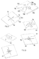
- Fig. 10 illustrates ways to connect a sample rack to different functional areas of a flow cell.
- the receiving area of a sample carrier with a conical carrier element protrudes into a mixing chamber 41 of a flow cell, wherein it is connected to the chamber wall via a conical interference fit.
- the mixing chamber can be partially or completely filled with rinsing liquid, for example from a reagent storage, whereby the sample is detached from the sample carrier and diluted.
- the flow cell is preferably in a vertical position, so that through a transparent cover 43 through the liquid level in the mixing chamber can be controlled and / or air in the mixing chamber can escape during the mixing process.
- the diluted sample may be transported through channel 42 or another channel connected to the mixing chamber for further analysis or processing within the flow cell.
- the flow cell and the sample carrier may have structures, such as snap closures, undercuts or latching lugs, which engage in a single connection of the sample carrier with the flow cell and prevent removal of the sample carrier after the connection with the flow cell.
- a the sample carrier of Fig. 5a corresponding sample carrier is according to Fig. 10b connected to a chamber 44 which is located near but outside a center of rotation of the flow cell.
- the fluid transport takes place partially or completely by centrifugation.
- the sample is also transported almost completely by centrifugal force into a channel 44a connected to the transport chamber 44 for further analysis. In the manner described, an undiluted liquid sample can be removed.
- a sample receiving area of a sample carrier with conical carrier element projects into a transport channel 45 of a flow cell.
- the end of the conical sample holder reaches up to a cover foil 46 of the flow cell.
- the sample carrier and the flow cells have an alignment member 47 and 48, respectively, to ensure that a groove-shaped sample receiving area is aligned with the transport channel 45.
- the sample can be transported pneumatically or hydraulically from the sample receiving area in the transport channel 45 of the flow cell to further processing devices.
- alignment structures such as a slot 49 or the like, are provided which indicate that a sample carrier is aligned with a groove-shaped sample receiving area transverse to the longitudinal direction of a transport channel.
- a sample carrier is still rotatable despite the press fit and can from such a position in the in Fig. 5d shown position where according to example of Fig. 10c the emptying of the sample receiving area can take place.
- Out Fig. 11 is a connection of the sample of Fig. 5 with a flow cell.
- the rinsing channel 30 of the sample carrier is connected to a channel 50 of the flow cell, via which, according to arrow 51, compressed air or rinsing liquid is supplied, which presses the sample quantity 32 into a further channel 52 of the flow cell.
- Plastics generally have hydrophobic, for aqueous fluids, such as blood, poorly wettable surfaces.
- hydrophilic surfaces are advantageous, also with regard to an exact dimensioning of sample quantities.
- Changes (hydrophilic or hydrophobic) of the surface properties of plastics are known to be wet-chemically by applying wetting agents or surfactants and subsequent drying, by surface activation by plasma, flaming or corona treatment (hydrophilic), by surface coating by plasma polymerization, eg formation of glassy layers (hydrophilic or hydrophobic) or through combinations of these measures.
- Fig. 13a shows a sample carrier, the sample receiving region 57 and the conical sealing region is coated hydrophilic, for example with a glassy layer.
- the contact angle to water is ⁇ 50 °.
- a surface treatment is limited to a groove-shaped receiving region 58, which may be hydrophilically modified, for example, by wet-chemical treatment or masked plasma coating.
- the sample intake preferably takes place by dipping the sample carrier into a sample drop, for example blood on a fingertip.
- the amount of sample taken is defined by the geometry of the hydrophilically modified sample receiving area. In the adjacent areas with a hydrophobic surface, the sample hardly or not at all adheres.
- Fig. 13c corresponds to the previous embodiment, but additionally has a hydrophobic coating 60 outside of the sample receiving area 59.
- the typical contact angle is> 90 ° in order to further increase the contrast of the wettability between the recording area and the adjacent area and thus to measure the sample quantities even more precisely.
- Fig. 13d shows an embodiment of a sample carrier, which consists of two different wettable plastics.
- a core part 56 of a conical carrier element has a contact angle ⁇ 70 °, for example PMMA, while an outer region of the conical carrier element, which consists for example of olefin plastic such as PP, has a contact angle> 90 °.
- the geometry of the core part 56 is cylindrical.
- the combination of materials is chosen so that both materials (eg PP and PMMA, PP and POM) do not bond firmly but rather movably in two-component injection molding.
- Fig. 13e is compared to the embodiment of Fig. 13b formed a groove-shaped sample receiving area, which is closed on one side with a film 61, but open at the ends.
- the inner walls of this channel-shaped receiving area can be hydrophilic, for example wet-chemically or by plasma treatment.
- a sample receiving area is partially or completely coated with a dry reagent 62 and functionalized.
- a sample can be conditioned directly after the recording by the sample carrier before a connection of the sample carrier takes place with a flow cell or other processing device.
- an anticoagulation reagent may be applied which, for example, prevents blood from clotting on the sample carrier, with materials such as heparin or citrate being suitable for this purpose.
- the dry reagent may also be a lysis buffer for lysing cells, eg a blood sample.
- Fig. 14a again a sample carrier with a
- the conical carrier element is shown cup-shaped surrounding handling area
- the embodiment of Fig. 14b a sample carrier with a conical handle 64 and a receiving area 63.
- Fig. 14c is a conical handle portion 65 at a predetermined breaking point 66 after connection of the sample carrier, eg with a flow cell, break off.
- Fig. 14d shows a sample carrier with a recess 67, in which a after connection of the sample carrier, for example, with a flow cell, detachable handling pin 68 is used.
- a conically widening sample receiving space 79 is formed, which is delimited by a plasma separation membrane 80, which first stops the capillary filling of the sample receiving space 79 with a blood sample.
- a second, with the first molded part 81 glued or welded conical injection part 82 has a capillary fillable passage 83. Both the sample receiving space 79 and the passage 73 are hydrophilically coated on the inside. Via the conical injection part 82, the sample carrier can be connected to a flow cell.
- plasma After filling a blood sample into the receiving space 79, plasma enters the passageway 83 through the plasma separation membrane 80, the open end of which forms a capillary stop metering the plasma sample.
- the first injection molded part 81 can serve as a grip element, wherein expediently a cover cap is used to possibly prevent contamination of the environment by remaining in the receiving space 79 blood.
- the blood plasma to be analyzed by the flow cell can be sucked out of the passage by means of a fleece or a membrane adjoining the opening of the passage 83.
- Fig. 16 shows a one-piece as a plastic injection molded sample carrier having a passage 86 with a constriction 85.
- Passage 86 forms a sample receiving capillary 84 as far as restriction 85.
- Passage 86 passes through a conical element and a handle portion integrally connected to the conical element. Between the handle part and the conical element an annular shoulder 87 is formed.
- the passage 86 When receiving a sample in the sample receiving capillary 84, the remaining passage 86 forms a vent passage.
- the passage 86 may further form a flushing channel for flushing the sample into the flow cell.
- Fig. 17 shows the sample carrier of Fig. 16 in conjunction with a pen-like handling device 88 which can be attached with one end to the annular shoulder 87 and with a conical inner wall 93 to a conical end of the sample carrier and can serve for attaching the sample carrier to a flow cell.
- the handling device has a core element 89 that can be moved in the axial direction in the manner of a ballpoint pen refill, in accordance with its movement Fig. 17c a detachment of the handling device 88 can be done by the plugged onto the flow cell sample carrier.
- the core element 89 can also have a clamping projection 92 for engagement in the passage 86 of the sample carrier.
- the clamping is provided such that a venting of the sample channel is not disturbed thereby.
- the outer part of the handling device 88 advanced relative to the core member 89 under pressure against the annular shoulder 87.
- Fig. 19 indicates that the sample carrier could also have a sample receiving region 90 in the manner of a groove or depression, as described above in connection with, for example, the sample carrier 7 of FIG Fig. 4 is described.
- the core element 89 of the handling device 88 could then clampingly engage in a longitudinal channel 91 of the sample carrier.
- Fig. 20 shows a metering element with a conical plug neck 94, over which it has an in Fig. 21 illustrated flow cell can be plugged.
- the plug approach 94 has a groove channel 95 in an end wall at the free end and is connected to a comprehensive two-rotary knob 96, each with a stop 97 and 98 on the wings.
- FIG. 21 illustrated flow cell has a conical plug-in opening 99 for receiving the plug neck 94.
- a sample can be introduced into the flow cell with the aid of a pipette or syringe.
- the input port 100 communicates via a channel 101 and the plug-in opening 99 in conjunction with an overflow port 102.
- the flow cell consists of a plate 103 and a sheet 104 which is glued or welded to the plate and covers the channel 101.
- the flow cell further has purge ports 105 and 106 communicating with each other via a passage 107.
- stops 108 and 109 are formed on the side facing away from the channels 101,107 side.
- the dosing element is inserted with the plug projection 94 first into the plug-in opening 99 of the flow cell, wherein the groove channel 95 is covered by the film 104.
- the dosing element is located in the in Fig. 22a shown rotational position in which the wings of the rotary handle 96 abut against the stops 108 and 109. In this position added according to Fig. 22b the groove channel 95 of the conical plug boss 94, the channel 101 between the input port 100 and the overflow port 102. A filled in the input port 100 sample material can flow into the overflow port 102.
- the metering element is rotated by 90 °, according to Fig. 22c with its stops 97 and 98 against the input port 100 and overflow port 102 is present ( Fig. 22c ).
- the openings of the ports are sealed in this position by the wings of the rotary handle 96.
- a sample amount is measured, which corresponds to the internal volume of the groove channel 95.
- the groove channel 95 supplements the channel 107 between the flushing connections 105, 106.
- the metering amount of a sample contained in the groove channel 95 can therefore be flushed out of the flow cell via the flushing connections 105 and 106 and sent for further processing.
Landscapes
- Chemical & Material Sciences (AREA)
- Health & Medical Sciences (AREA)
- Dispersion Chemistry (AREA)
- Analytical Chemistry (AREA)
- General Health & Medical Sciences (AREA)
- Hematology (AREA)
- Clinical Laboratory Science (AREA)
- Chemical Kinetics & Catalysis (AREA)
- Automatic Analysis And Handling Materials Therefor (AREA)
- Investigating Or Analysing Biological Materials (AREA)
Priority Applications (3)
| Application Number | Priority Date | Filing Date | Title |
|---|---|---|---|
| EP15173174.2A EP3108962A1 (fr) | 2015-06-22 | 2015-06-22 | Porte échantillons |
| PCT/EP2016/060498 WO2016206854A1 (fr) | 2015-06-22 | 2016-05-11 | Porte-échantillon |
| US15/738,421 US11045802B2 (en) | 2015-06-22 | 2016-05-11 | Sample carrier |
Applications Claiming Priority (1)
| Application Number | Priority Date | Filing Date | Title |
|---|---|---|---|
| EP15173174.2A EP3108962A1 (fr) | 2015-06-22 | 2015-06-22 | Porte échantillons |
Publications (1)
| Publication Number | Publication Date |
|---|---|
| EP3108962A1 true EP3108962A1 (fr) | 2016-12-28 |
Family
ID=53496441
Family Applications (1)
| Application Number | Title | Priority Date | Filing Date |
|---|---|---|---|
| EP15173174.2A Pending EP3108962A1 (fr) | 2015-06-22 | 2015-06-22 | Porte échantillons |
Country Status (3)
| Country | Link |
|---|---|
| US (1) | US11045802B2 (fr) |
| EP (1) | EP3108962A1 (fr) |
| WO (1) | WO2016206854A1 (fr) |
Cited By (3)
| Publication number | Priority date | Publication date | Assignee | Title |
|---|---|---|---|---|
| WO2019142141A1 (fr) * | 2018-01-18 | 2019-07-25 | Holger Engel | Récipient pour produit chimique sec |
| EP3747542A1 (fr) | 2019-06-07 | 2020-12-09 | Thinxxs Microtechnology Ag | Système de transfert pour échantillons, en particulier échantillons à analyser |
| US11426725B2 (en) * | 2016-06-30 | 2022-08-30 | Thinxxs Microtechnology Gmbh | Flow cell having a reagent reservoir |
Families Citing this family (3)
| Publication number | Priority date | Publication date | Assignee | Title |
|---|---|---|---|---|
| EP3342485B1 (fr) * | 2017-01-02 | 2020-07-08 | Thinxxs Microtechnology Ag | Supports d'éléments de réactifs |
| CN112292602B (zh) * | 2018-11-30 | 2024-09-03 | 积水化学工业株式会社 | 测定工具和送液方法 |
| US20220161262A1 (en) * | 2019-04-08 | 2022-05-26 | Withings | System and apparatus for injecting droplets in a microfluidic system |
Citations (5)
| Publication number | Priority date | Publication date | Assignee | Title |
|---|---|---|---|---|
| DE9417612U1 (de) * | 1994-11-03 | 1995-01-05 | Kloth, Bernd, 22399 Hamburg | Probenabnahmegerät |
| WO2000074853A1 (fr) | 1999-06-04 | 2000-12-14 | Axis-Shield Poc As | Recipient, sa fermeture et procede de melange de deux substances |
| US20040156746A1 (en) * | 2001-05-10 | 2004-08-12 | Larsen Ulrik Darling | Device for sampling small and precise volumes of liquid |
| WO2005094681A1 (fr) | 2004-03-26 | 2005-10-13 | Sarstedt Ag & Co. | Dispositif pour prelevement de sang capillaire |
| EP2821138A1 (fr) * | 2013-07-05 | 2015-01-07 | Thinxxs Microtechnology Ag | Cellule d'écoulement avec substance de séchage intégrée |
Family Cites Families (14)
| Publication number | Priority date | Publication date | Assignee | Title |
|---|---|---|---|---|
| US5257984A (en) * | 1991-10-02 | 1993-11-02 | Norfolk Scientific, Inc. | Blood collector |
| US6319209B1 (en) * | 1999-08-23 | 2001-11-20 | European Institute Of Science | Disposable test vial with sample delivery device for dispensing sample into a reagent |
| US7863035B2 (en) * | 2007-02-15 | 2011-01-04 | Osmetech Technology Inc. | Fluidics devices |
| EP3206009A1 (fr) * | 2008-08-21 | 2017-08-16 | DNA Genotek Inc. | Dispositif de réception d'échantillons |
| DE102008054313B4 (de) * | 2008-11-03 | 2012-12-13 | Zenteris Gmbh | Kartusche und Vorrichtung zur Untersuchung biologischer Proben mit temperaturgesteuerten biologischen Reaktionen |
| GB2473425A (en) * | 2009-09-03 | 2011-03-16 | Vivacta Ltd | Fluid Sample Collection Device |
| US9874555B2 (en) * | 2012-04-12 | 2018-01-23 | Becton, Dickinson And Company | Methods, systems, and devices for detecting and identifying microorganisms in microbiological culture samples |
| PL2676606T3 (pl) * | 2012-06-20 | 2017-10-31 | Fabpulous B V | Szybko testujące urządzenie i sposób |
| US9592507B2 (en) * | 2012-06-22 | 2017-03-14 | Abbott Point Of Care Inc. | Integrated cartridge housings for sample analysis |
| EP2972313B1 (fr) * | 2013-03-15 | 2018-01-03 | Rinker, Kristina, D. | Chambre d'écoulement à plaques parallèles à orifices et leurs procédés d'utilisation |
| US20140295441A1 (en) | 2013-03-27 | 2014-10-02 | Zygem Corporation Ltd. | Cartridge interface module |
| AU2015263381B2 (en) * | 2014-05-21 | 2019-04-11 | Orion Diagnostica Oy | Sampling and assay kit, sample holder and method |
| EP2982436B1 (fr) | 2014-08-04 | 2020-09-09 | Skyla Corporation Hsinchu Science Park Branch | Module de test pour un échantillon d'essai |
| JP6823589B2 (ja) | 2014-09-11 | 2021-02-03 | キュー ヘルス インコーポレイテッド | 被分析物の検出および定量のためのシステム |
-
2015
- 2015-06-22 EP EP15173174.2A patent/EP3108962A1/fr active Pending
-
2016
- 2016-05-11 WO PCT/EP2016/060498 patent/WO2016206854A1/fr active Application Filing
- 2016-05-11 US US15/738,421 patent/US11045802B2/en active Active
Patent Citations (5)
| Publication number | Priority date | Publication date | Assignee | Title |
|---|---|---|---|---|
| DE9417612U1 (de) * | 1994-11-03 | 1995-01-05 | Kloth, Bernd, 22399 Hamburg | Probenabnahmegerät |
| WO2000074853A1 (fr) | 1999-06-04 | 2000-12-14 | Axis-Shield Poc As | Recipient, sa fermeture et procede de melange de deux substances |
| US20040156746A1 (en) * | 2001-05-10 | 2004-08-12 | Larsen Ulrik Darling | Device for sampling small and precise volumes of liquid |
| WO2005094681A1 (fr) | 2004-03-26 | 2005-10-13 | Sarstedt Ag & Co. | Dispositif pour prelevement de sang capillaire |
| EP2821138A1 (fr) * | 2013-07-05 | 2015-01-07 | Thinxxs Microtechnology Ag | Cellule d'écoulement avec substance de séchage intégrée |
Cited By (5)
| Publication number | Priority date | Publication date | Assignee | Title |
|---|---|---|---|---|
| US11426725B2 (en) * | 2016-06-30 | 2022-08-30 | Thinxxs Microtechnology Gmbh | Flow cell having a reagent reservoir |
| WO2019142141A1 (fr) * | 2018-01-18 | 2019-07-25 | Holger Engel | Récipient pour produit chimique sec |
| US12042793B2 (en) | 2018-01-18 | 2024-07-23 | Qiagen Gmbh | Dry chemistry container |
| EP3747542A1 (fr) | 2019-06-07 | 2020-12-09 | Thinxxs Microtechnology Ag | Système de transfert pour échantillons, en particulier échantillons à analyser |
| WO2020244864A1 (fr) | 2019-06-07 | 2020-12-10 | Thinxxs Microtechnology Ag | Système de transfert pour des échantillons, en particulier pour des échantillons à analyser |
Also Published As
| Publication number | Publication date |
|---|---|
| WO2016206854A1 (fr) | 2016-12-29 |
| US11045802B2 (en) | 2021-06-29 |
| US20180185841A1 (en) | 2018-07-05 |
Similar Documents
| Publication | Publication Date | Title |
|---|---|---|
| WO2016206854A1 (fr) | Porte-échantillon | |
| EP3164212B1 (fr) | Réservoir de réactif pour fluides | |
| EP2632590B1 (fr) | Support de test microfluidique pour diviser une quantité de liquide en quantités partielles | |
| EP3541516B1 (fr) | Dispositif de prélèvement, d'expulsion et de déplacement de liquides | |
| EP2413138B1 (fr) | Dispositif et procédé de séparation de composants d'un liquide d'échantillon | |
| EP2428272B1 (fr) | Procédé de revêtement hyrophobe d'embouts de pipette | |
| EP2654955B1 (fr) | Procédé de mélange d'au moins une solution d'échantillon avec des réactifs | |
| DE10238266A1 (de) | Mikrofluidsystem | |
| DE102018111822B4 (de) | Fluidisches System zur Aufnahme, Abgabe und Bewegung von Flüssigkeiten, Verfahren zur Verarbeitung von Fluiden in einem fluidischen System | |
| EP2506959A1 (fr) | Élément microfluidique pour l'analyse d'un échantillon liquide | |
| WO2003068398A1 (fr) | Dispositif de preparation d'echantillons et appareillage d'essai faisant appel a ce dernier | |
| EP3263215B1 (fr) | Dispositif comprenant un cellule comprenant un dispositif de stockage de reactif | |
| EP1541986A1 (fr) | Dispositif d'échantillonage pour l'analyse d'un échantillon fluide | |
| DE102011079698B4 (de) | Mikrofluidische Vorrichtung mit einer Kammer zur Lagerung einer Flüssigkeit | |
| EP2834006A1 (fr) | Élément enceinte pour récipient à réactifs et son utilisation | |
| DE102016222028A1 (de) | Mikrofluidischer Behälter | |
| DE102016015944B3 (de) | Mikrofluidisches System zur Aufnahme, Abgabe und Bewegung von Fluiden | |
| EP3649471B1 (fr) | Module d'analyse de fluide et analyseur de fluide | |
| EP4414075A2 (fr) | Porte-échantillon centrifugable | |
| EP3747542A1 (fr) | Système de transfert pour échantillons, en particulier échantillons à analyser | |
| WO2024023229A1 (fr) | Dispositif de réception d'échantillon | |
| EP2834005B1 (fr) | Dispositif capillaire pour récipient pour réactif et l'utilisation | |
| DE102019007512A1 (de) | Mikrofluidische Vorrichtung zur Aufnahme von Flüssigkeiten und zugehöriges Verfahren | |
| EP2759343A1 (fr) | Unité de stockage d'un fluide et procédé pour la fabrication d'une unité de stockage d'un fluide |
Legal Events
| Date | Code | Title | Description |
|---|---|---|---|
| PUAI | Public reference made under article 153(3) epc to a published international application that has entered the european phase |
Free format text: ORIGINAL CODE: 0009012 |
|
| STAA | Information on the status of an ep patent application or granted ep patent |
Free format text: STATUS: THE APPLICATION HAS BEEN PUBLISHED |
|
| AK | Designated contracting states |
Kind code of ref document: A1 Designated state(s): AL AT BE BG CH CY CZ DE DK EE ES FI FR GB GR HR HU IE IS IT LI LT LU LV MC MK MT NL NO PL PT RO RS SE SI SK SM TR |
|
| AX | Request for extension of the european patent |
Extension state: BA ME |
|
| STAA | Information on the status of an ep patent application or granted ep patent |
Free format text: STATUS: REQUEST FOR EXAMINATION WAS MADE |
|
| 17P | Request for examination filed |
Effective date: 20170628 |
|
| RBV | Designated contracting states (corrected) |
Designated state(s): AL AT BE BG CH CY CZ DE DK EE ES FI FR GB GR HR HU IE IS IT LI LT LU LV MC MK MT NL NO PL PT RO RS SE SI SK SM TR |
|
| STAA | Information on the status of an ep patent application or granted ep patent |
Free format text: STATUS: EXAMINATION IS IN PROGRESS |
|
| 17Q | First examination report despatched |
Effective date: 20180322 |
|
| STAA | Information on the status of an ep patent application or granted ep patent |
Free format text: STATUS: EXAMINATION IS IN PROGRESS |
|
| STAA | Information on the status of an ep patent application or granted ep patent |
Free format text: STATUS: EXAMINATION IS IN PROGRESS |
|
| RAP3 | Party data changed (applicant data changed or rights of an application transferred) |
Owner name: THINXXS MICROTECHNOLOGY GMBH |
|
| GRAP | Despatch of communication of intention to grant a patent |
Free format text: ORIGINAL CODE: EPIDOSNIGR1 |
|
| STAA | Information on the status of an ep patent application or granted ep patent |
Free format text: STATUS: GRANT OF PATENT IS INTENDED |
|
| INTG | Intention to grant announced |
Effective date: 20240523 |
|
| GRAS | Grant fee paid |
Free format text: ORIGINAL CODE: EPIDOSNIGR3 |
|
| GRAA | (expected) grant |
Free format text: ORIGINAL CODE: 0009210 |
|
| STAA | Information on the status of an ep patent application or granted ep patent |
Free format text: STATUS: THE PATENT HAS BEEN GRANTED |