US11267174B2 - Insert-molded container manufacturing method - Google Patents
Insert-molded container manufacturing method Download PDFInfo
- Publication number
- US11267174B2 US11267174B2 US16/631,371 US201816631371A US11267174B2 US 11267174 B2 US11267174 B2 US 11267174B2 US 201816631371 A US201816631371 A US 201816631371A US 11267174 B2 US11267174 B2 US 11267174B2
- Authority
- US
- United States
- Prior art keywords
- container
- insert
- vapor
- synthetic resin
- deposited layer
- Prior art date
- Legal status (The legal status is an assumption and is not a legal conclusion. Google has not performed a legal analysis and makes no representation as to the accuracy of the status listed.)
- Active, expires
Links
Images


Classifications
-
- B—PERFORMING OPERATIONS; TRANSPORTING
- B29—WORKING OF PLASTICS; WORKING OF SUBSTANCES IN A PLASTIC STATE IN GENERAL
- B29C—SHAPING OR JOINING OF PLASTICS; SHAPING OF MATERIAL IN A PLASTIC STATE, NOT OTHERWISE PROVIDED FOR; AFTER-TREATMENT OF THE SHAPED PRODUCTS, e.g. REPAIRING
- B29C45/00—Injection moulding, i.e. forcing the required volume of moulding material through a nozzle into a closed mould; Apparatus therefor
- B29C45/0001—Injection moulding, i.e. forcing the required volume of moulding material through a nozzle into a closed mould; Apparatus therefor characterised by the choice of material
-
- B—PERFORMING OPERATIONS; TRANSPORTING
- B29—WORKING OF PLASTICS; WORKING OF SUBSTANCES IN A PLASTIC STATE IN GENERAL
- B29C—SHAPING OR JOINING OF PLASTICS; SHAPING OF MATERIAL IN A PLASTIC STATE, NOT OTHERWISE PROVIDED FOR; AFTER-TREATMENT OF THE SHAPED PRODUCTS, e.g. REPAIRING
- B29C45/00—Injection moulding, i.e. forcing the required volume of moulding material through a nozzle into a closed mould; Apparatus therefor
- B29C45/16—Making multilayered or multicoloured articles
- B29C45/1671—Making multilayered or multicoloured articles with an insert
-
- B—PERFORMING OPERATIONS; TRANSPORTING
- B29—WORKING OF PLASTICS; WORKING OF SUBSTANCES IN A PLASTIC STATE IN GENERAL
- B29C—SHAPING OR JOINING OF PLASTICS; SHAPING OF MATERIAL IN A PLASTIC STATE, NOT OTHERWISE PROVIDED FOR; AFTER-TREATMENT OF THE SHAPED PRODUCTS, e.g. REPAIRING
- B29C45/00—Injection moulding, i.e. forcing the required volume of moulding material through a nozzle into a closed mould; Apparatus therefor
- B29C45/0025—Preventing defects on the moulded article, e.g. weld lines, shrinkage marks
-
- B—PERFORMING OPERATIONS; TRANSPORTING
- B29—WORKING OF PLASTICS; WORKING OF SUBSTANCES IN A PLASTIC STATE IN GENERAL
- B29C—SHAPING OR JOINING OF PLASTICS; SHAPING OF MATERIAL IN A PLASTIC STATE, NOT OTHERWISE PROVIDED FOR; AFTER-TREATMENT OF THE SHAPED PRODUCTS, e.g. REPAIRING
- B29C45/00—Injection moulding, i.e. forcing the required volume of moulding material through a nozzle into a closed mould; Apparatus therefor
- B29C45/14—Injection moulding, i.e. forcing the required volume of moulding material through a nozzle into a closed mould; Apparatus therefor incorporating preformed parts or layers, e.g. injection moulding around inserts or for coating articles
- B29C45/14336—Coating a portion of the article, e.g. the edge of the article
- B29C45/14377—Coating a portion of the article, e.g. the edge of the article using an additional insert, e.g. a fastening element
-
- B—PERFORMING OPERATIONS; TRANSPORTING
- B29—WORKING OF PLASTICS; WORKING OF SUBSTANCES IN A PLASTIC STATE IN GENERAL
- B29C—SHAPING OR JOINING OF PLASTICS; SHAPING OF MATERIAL IN A PLASTIC STATE, NOT OTHERWISE PROVIDED FOR; AFTER-TREATMENT OF THE SHAPED PRODUCTS, e.g. REPAIRING
- B29C45/00—Injection moulding, i.e. forcing the required volume of moulding material through a nozzle into a closed mould; Apparatus therefor
- B29C45/14—Injection moulding, i.e. forcing the required volume of moulding material through a nozzle into a closed mould; Apparatus therefor incorporating preformed parts or layers, e.g. injection moulding around inserts or for coating articles
- B29C45/14467—Joining articles or parts of a single article
-
- B—PERFORMING OPERATIONS; TRANSPORTING
- B29—WORKING OF PLASTICS; WORKING OF SUBSTANCES IN A PLASTIC STATE IN GENERAL
- B29C—SHAPING OR JOINING OF PLASTICS; SHAPING OF MATERIAL IN A PLASTIC STATE, NOT OTHERWISE PROVIDED FOR; AFTER-TREATMENT OF THE SHAPED PRODUCTS, e.g. REPAIRING
- B29C45/00—Injection moulding, i.e. forcing the required volume of moulding material through a nozzle into a closed mould; Apparatus therefor
- B29C45/14—Injection moulding, i.e. forcing the required volume of moulding material through a nozzle into a closed mould; Apparatus therefor incorporating preformed parts or layers, e.g. injection moulding around inserts or for coating articles
- B29C45/14688—Coating articles provided with a decoration
-
- B—PERFORMING OPERATIONS; TRANSPORTING
- B29—WORKING OF PLASTICS; WORKING OF SUBSTANCES IN A PLASTIC STATE IN GENERAL
- B29C—SHAPING OR JOINING OF PLASTICS; SHAPING OF MATERIAL IN A PLASTIC STATE, NOT OTHERWISE PROVIDED FOR; AFTER-TREATMENT OF THE SHAPED PRODUCTS, e.g. REPAIRING
- B29C45/00—Injection moulding, i.e. forcing the required volume of moulding material through a nozzle into a closed mould; Apparatus therefor
- B29C45/14—Injection moulding, i.e. forcing the required volume of moulding material through a nozzle into a closed mould; Apparatus therefor incorporating preformed parts or layers, e.g. injection moulding around inserts or for coating articles
- B29C45/14778—Injection moulding, i.e. forcing the required volume of moulding material through a nozzle into a closed mould; Apparatus therefor incorporating preformed parts or layers, e.g. injection moulding around inserts or for coating articles the article consisting of a material with particular properties, e.g. porous, brittle
- B29C45/14811—Multilayered articles
-
- B—PERFORMING OPERATIONS; TRANSPORTING
- B29—WORKING OF PLASTICS; WORKING OF SUBSTANCES IN A PLASTIC STATE IN GENERAL
- B29C—SHAPING OR JOINING OF PLASTICS; SHAPING OF MATERIAL IN A PLASTIC STATE, NOT OTHERWISE PROVIDED FOR; AFTER-TREATMENT OF THE SHAPED PRODUCTS, e.g. REPAIRING
- B29C45/00—Injection moulding, i.e. forcing the required volume of moulding material through a nozzle into a closed mould; Apparatus therefor
- B29C45/14—Injection moulding, i.e. forcing the required volume of moulding material through a nozzle into a closed mould; Apparatus therefor incorporating preformed parts or layers, e.g. injection moulding around inserts or for coating articles
- B29C45/14836—Preventing damage of inserts during injection, e.g. collapse of hollow inserts, breakage
-
- B—PERFORMING OPERATIONS; TRANSPORTING
- B29—WORKING OF PLASTICS; WORKING OF SUBSTANCES IN A PLASTIC STATE IN GENERAL
- B29C—SHAPING OR JOINING OF PLASTICS; SHAPING OF MATERIAL IN A PLASTIC STATE, NOT OTHERWISE PROVIDED FOR; AFTER-TREATMENT OF THE SHAPED PRODUCTS, e.g. REPAIRING
- B29C45/00—Injection moulding, i.e. forcing the required volume of moulding material through a nozzle into a closed mould; Apparatus therefor
- B29C45/0025—Preventing defects on the moulded article, e.g. weld lines, shrinkage marks
- B29C2045/0027—Gate or gate mark locations
-
- B—PERFORMING OPERATIONS; TRANSPORTING
- B29—WORKING OF PLASTICS; WORKING OF SUBSTANCES IN A PLASTIC STATE IN GENERAL
- B29C—SHAPING OR JOINING OF PLASTICS; SHAPING OF MATERIAL IN A PLASTIC STATE, NOT OTHERWISE PROVIDED FOR; AFTER-TREATMENT OF THE SHAPED PRODUCTS, e.g. REPAIRING
- B29C45/00—Injection moulding, i.e. forcing the required volume of moulding material through a nozzle into a closed mould; Apparatus therefor
- B29C45/14—Injection moulding, i.e. forcing the required volume of moulding material through a nozzle into a closed mould; Apparatus therefor incorporating preformed parts or layers, e.g. injection moulding around inserts or for coating articles
- B29C45/14065—Positioning or centering articles in the mould
- B29C2045/14131—Positioning or centering articles in the mould using positioning or centering means forming part of the insert
-
- B—PERFORMING OPERATIONS; TRANSPORTING
- B29—WORKING OF PLASTICS; WORKING OF SUBSTANCES IN A PLASTIC STATE IN GENERAL
- B29C—SHAPING OR JOINING OF PLASTICS; SHAPING OF MATERIAL IN A PLASTIC STATE, NOT OTHERWISE PROVIDED FOR; AFTER-TREATMENT OF THE SHAPED PRODUCTS, e.g. REPAIRING
- B29C45/00—Injection moulding, i.e. forcing the required volume of moulding material through a nozzle into a closed mould; Apparatus therefor
- B29C45/14—Injection moulding, i.e. forcing the required volume of moulding material through a nozzle into a closed mould; Apparatus therefor incorporating preformed parts or layers, e.g. injection moulding around inserts or for coating articles
- B29C45/14311—Injection moulding, i.e. forcing the required volume of moulding material through a nozzle into a closed mould; Apparatus therefor incorporating preformed parts or layers, e.g. injection moulding around inserts or for coating articles using means for bonding the coating to the articles
- B29C2045/14319—Injection moulding, i.e. forcing the required volume of moulding material through a nozzle into a closed mould; Apparatus therefor incorporating preformed parts or layers, e.g. injection moulding around inserts or for coating articles using means for bonding the coating to the articles bonding by a fusion bond
-
- B—PERFORMING OPERATIONS; TRANSPORTING
- B29—WORKING OF PLASTICS; WORKING OF SUBSTANCES IN A PLASTIC STATE IN GENERAL
- B29C—SHAPING OR JOINING OF PLASTICS; SHAPING OF MATERIAL IN A PLASTIC STATE, NOT OTHERWISE PROVIDED FOR; AFTER-TREATMENT OF THE SHAPED PRODUCTS, e.g. REPAIRING
- B29C45/00—Injection moulding, i.e. forcing the required volume of moulding material through a nozzle into a closed mould; Apparatus therefor
- B29C45/14—Injection moulding, i.e. forcing the required volume of moulding material through a nozzle into a closed mould; Apparatus therefor incorporating preformed parts or layers, e.g. injection moulding around inserts or for coating articles
- B29C45/14688—Coating articles provided with a decoration
- B29C2045/14713—Coating articles provided with a decoration decorations in contact with injected material
-
- B—PERFORMING OPERATIONS; TRANSPORTING
- B29—WORKING OF PLASTICS; WORKING OF SUBSTANCES IN A PLASTIC STATE IN GENERAL
- B29C—SHAPING OR JOINING OF PLASTICS; SHAPING OF MATERIAL IN A PLASTIC STATE, NOT OTHERWISE PROVIDED FOR; AFTER-TREATMENT OF THE SHAPED PRODUCTS, e.g. REPAIRING
- B29C45/00—Injection moulding, i.e. forcing the required volume of moulding material through a nozzle into a closed mould; Apparatus therefor
- B29C45/14—Injection moulding, i.e. forcing the required volume of moulding material through a nozzle into a closed mould; Apparatus therefor incorporating preformed parts or layers, e.g. injection moulding around inserts or for coating articles
- B29C45/14688—Coating articles provided with a decoration
- B29C2045/14729—Coating articles provided with a decoration decorations not in contact with injected material
-
- B—PERFORMING OPERATIONS; TRANSPORTING
- B29—WORKING OF PLASTICS; WORKING OF SUBSTANCES IN A PLASTIC STATE IN GENERAL
- B29C—SHAPING OR JOINING OF PLASTICS; SHAPING OF MATERIAL IN A PLASTIC STATE, NOT OTHERWISE PROVIDED FOR; AFTER-TREATMENT OF THE SHAPED PRODUCTS, e.g. REPAIRING
- B29C45/00—Injection moulding, i.e. forcing the required volume of moulding material through a nozzle into a closed mould; Apparatus therefor
- B29C45/14—Injection moulding, i.e. forcing the required volume of moulding material through a nozzle into a closed mould; Apparatus therefor incorporating preformed parts or layers, e.g. injection moulding around inserts or for coating articles
- B29C45/14836—Preventing damage of inserts during injection, e.g. collapse of hollow inserts, breakage
- B29C2045/14844—Layers protecting the insert from injected material
-
- B—PERFORMING OPERATIONS; TRANSPORTING
- B29—WORKING OF PLASTICS; WORKING OF SUBSTANCES IN A PLASTIC STATE IN GENERAL
- B29K—INDEXING SCHEME ASSOCIATED WITH SUBCLASSES B29B, B29C OR B29D, RELATING TO MOULDING MATERIALS OR TO MATERIALS FOR MOULDS, REINFORCEMENTS, FILLERS OR PREFORMED PARTS, e.g. INSERTS
- B29K2067/00—Use of polyesters or derivatives thereof, as moulding material
-
- B—PERFORMING OPERATIONS; TRANSPORTING
- B29—WORKING OF PLASTICS; WORKING OF SUBSTANCES IN A PLASTIC STATE IN GENERAL
- B29K—INDEXING SCHEME ASSOCIATED WITH SUBCLASSES B29B, B29C OR B29D, RELATING TO MOULDING MATERIALS OR TO MATERIALS FOR MOULDS, REINFORCEMENTS, FILLERS OR PREFORMED PARTS, e.g. INSERTS
- B29K2995/00—Properties of moulding materials, reinforcements, fillers, preformed parts or moulds
- B29K2995/0018—Properties of moulding materials, reinforcements, fillers, preformed parts or moulds having particular optical properties, e.g. fluorescent or phosphorescent
- B29K2995/0026—Transparent
-
- B—PERFORMING OPERATIONS; TRANSPORTING
- B29—WORKING OF PLASTICS; WORKING OF SUBSTANCES IN A PLASTIC STATE IN GENERAL
- B29L—INDEXING SCHEME ASSOCIATED WITH SUBCLASS B29C, RELATING TO PARTICULAR ARTICLES
- B29L2009/00—Layered products
- B29L2009/003—Layered products comprising a metal layer
-
- B—PERFORMING OPERATIONS; TRANSPORTING
- B29—WORKING OF PLASTICS; WORKING OF SUBSTANCES IN A PLASTIC STATE IN GENERAL
- B29L—INDEXING SCHEME ASSOCIATED WITH SUBCLASS B29C, RELATING TO PARTICULAR ARTICLES
- B29L2031/00—Other particular articles
- B29L2031/712—Containers; Packaging elements or accessories, Packages
- B29L2031/717—Cans, tins
Definitions
- the present disclosure relates to an insert-molded container and a manufacturing method thereof, the insert-molded container having a double-wall structure in which a secondary container that is made of transparent synthetic resin and covers the outer surface of a primary container is integrally provided on the outside of the primary container.
- An insert-molded container having a double-wall structure in which a secondary container that is made of transparent synthetic resin and covers the outer surface of a primary container is integrally provided on the outside of the primary container has been known. Since such an insert-molded container having a double-wall structure can exert an excellent optical decorating function, it is used for an application that requires product differentiation with upscale-looking packaging, such as a container containing cosmetics, for example.
- the above described insert-molded container is formed into a double-wall structure by using an insert molding technique in which a transparent synthetic resin material is injected from a gate of a mold into the mold in a state where the primary container is placed in the mold as an insert material (see, for example, Patent Literature 1 (PTL 1)).
- PTL 1 Patent Literature 1
- a glossy vapor-deposited layer such as an aluminum vapor-deposited layer is provided on the outer surface of the primary container.
- transparency is added to a gloss of the vapor-deposited layer, and more upscale-looking and highly aesthetic container can be provided.
- the disclosed invention is provided to solve the above described problem and to prevent a vapor-deposited layer of a primary container from being peeled off and to provide a more aesthetic insert-molded container.
- a disclosed insert-molded container manufacturing method is a manufacturing method of an insert-molded container having a double-wall structure in which a secondary container that is made of transparent synthetic resin and covers the outer surface of a primary container is integrally provided to the outside of the primary container.
- the method includes: a cover attaching step of attaching a cover member to an outer surface of a part provided with a vapor-deposited layer of the primary container provided with the vapor-deposited layer on an outer surface, the cover member covering a part of the vapor-deposited layer and made of transparent synthetic resin; a placing step of placing the primary container in a mold with the cover member facing a gate; and an insert molding step of integrally forming the secondary container on the outside of the primary container by injecting a transparent synthetic resin material from the gate into the mold.
- the primary container includes a side wall and a bottom wall
- the vapor-deposited layer is provided on the entire outer surface of the bottom wall
- the cover member is attached to the central part of the bottom wall.
- the cover member is formed of a synthetic resin material which is the same as that forms the secondary container.
- the primary container is provided with the vapor-deposited layer on the entire outer surface.
- the secondary container is formed of a polyester-based synthetic resin material.
- the vapor-deposited layer is an aluminum vapor-deposited layer.
- the primary container is formed of a synthetic resin material having a melting point higher than that of a synthetic resin material forming the secondary container.
- the primary container is an injection molding product.
- a disclosed insert-molded container is an insert-molded container having a double-wall structure in which a secondary container that covers the outer surface of a primary container and is made of transparent synthetic resin is integrally provided to the outside of the primary container.
- the container is characterized in that the secondary container has a gate mark, and a vapor-deposited layer is provided on the outer surface of the primary container in a peripheral area of the gate mark.
- the primary container includes a side wall and a bottom wall
- the gate mark faces a central part of the bottom wall
- the vapor-deposited layer is provided on the entire outer surface of the bottom wall.
- the vapor-deposited layer is provided on the entire outer surface of the primary container.
- the secondary container is formed of a polyester-based synthetic resin material.
- the vapor-deposited layer is an aluminum vapor-deposited layer.
- the primary container is formed of a synthetic resin material having a melting point higher than that of a synthetic resin material forming the secondary container.
- the primary container is an injection molding product.
- a vapor-deposited layer on a primary container is prevented from being peeled off and an insert-molded container with better aesthetics can be provided.
- FIG. 1 is a half cross-sectional view of an insert-molded container according to an embodiment of the present disclosure
- FIG. 2 is a cross-sectional view of a cosmetics container using the insert-molded container illustrated in FIG. 1 ;
- FIG. 3 is a half cross-sectional view illustrating, with a cover member, a primary container whose outer surface is provided with a vapor-deposited layer;
- FIG. 4A is a cross-sectional view of the primary container to which a cover member is attached in a cover attaching step
- FIG. 4B is a bottom view of the primary container in FIG. 4A ;
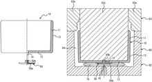
- FIG. 5 is a cross-sectional view illustrating a state where the primary container to which the cover member is attached is placed in a mold in a placing step;
- FIG. 6 is a cross-sectional view illustrating a state where a synthetic resin material is injected from a gate into the mold in an insert molding step
- FIG. 7 is a cross-sectional view illustrating a state where the insert molding step is finished.
- An insert-molded container 1 is an insert molding having a double-wall structure in which a secondary container 20 that covers an outer surface of a primary container 10 and is made of transparent synthetic resin is integrally provided to the outside of the primary container 10 .
- the insert-molded container 1 includes a cylindrical mouth 2 , a cylindrical body 3 being continuous to the mouth 2 and a circular bottom portion 4 that closes the lower end of the body 3 , and has a jar shape as a whole.
- the insert-molded container 1 can be used as a cosmetics container that contains cosmetics as contents.
- FIG. 2 illustrates a case where the insert-molded container 1 is formed as a refill type (replacing type) cosmetics container in which a refill container 30 filled with cosmetics is placed and the mouth 2 is blocked by a cap 40 .
- the refill container 30 has a sealed structure in which cosmetics 32 is filled inside a bottomed cylindrical refill container main body 31 having a shape corresponding to an inner surface of the insert-molded container 1 and a sheet-like blocking body 33 is fixed to an opening of the refill container 30 by means of adhesive and the like to seal the opening.
- the refill container main body 31 may be formed of a polypropylene resin, for example.
- the outer periphery of the upper end of the refill container main body 31 is provided with a claw locking portion 34 , which is in undercut engagement with a groove 2 a provided in the outer periphery of the upper end of the mouth 2 . In this manner the refill container 30 is held by the insert-molded container 1 in an attachable/detachable manner.
- the cap 40 is formed from polypropylene resin into a topped cylindrical shape having an outer diameter corresponding to that of the refill container main body 31 .
- a female thread 41 provided to the inner peripheral surface thereof is screw connected to a male thread 2 b provided on an outer peripheral surface of the mouth 2 . In this manner the cap 40 is attachable to and detachable from the insert-molded container 1 .
- Cosmetics 32 can be taken out of the refill container main body 31 and used by removing the cap 40 from the insert-molded container 1 and peeling off the blocking body 33 to open the refill container main body 31 . After use, the refill container main body 31 can be closed for storing the cosmetics by attaching the cap 40 to the insert-molded container 1 . When the cosmetics 32 are all removed and the refill container main body 31 gets empty, the empty refill container main body 31 is removed from the insert-molded container 1 and a new refill container 30 is placed in the insert-molded container 1 . In this manner the insert-molded container 1 can be reused.
- the contents may be directly contained in the insert-molded container 1 without using the refill container 30 .
- the primary container 10 is formed into a bottomed cylindrical shape including a cylindrical side wall 11 and a bottom wall 12 that closes the lower end of the side wall 11 .
- the side wall 11 forms the inner peripheral side of the body 3 of the insert-molded container 1 and the bottom wall 12 forms the upper surface side of the bottom 4 of the insert-molded container 1 .
- the primary container 10 is a polycarbonate injection molding product formed by injecting polycarbonate (PC).
- the primary container 10 may be made not only of polycarbonate but also of other synthetic resin materials or other materials such as glass and metal.
- the primary container 10 may be formed not only by injection molding of the synthetic resin material but also by blow molding thereof.
- the entire outer surface of the primary container 10 is provided with the vapor-deposited layer 13 . That is, the vapor-deposited layer 13 is provided on the entire outer surface of the side wall 11 facing outward and the entire outer surface of the bottom wall 12 facing outward, and thus all over the outer surface of the primary container 10 is covered by the vapor-deposited layer 13 . It is to be noted that the vapor-deposited layer 13 is not provided on the inner side surface of the primary container 10 , and the polycarbonate is exposed.
- the vapor-deposited layer 13 provided on the outer surface of the primary container 10 is an aluminum vapor-deposited layer. Since the vapor-deposited layer 13 , which is an aluminum vapor-deposited layer, is provided, the entire outer surface of the primary container 10 is decorated like a glossy mirror.
- the secondary container 20 is formed into a bottomed circular shape including the cylindrical side wall 21 and the bottom wall 22 that closes the lower end of the side wall 21 .
- the side wall 21 forms the outer peripheral side of the body 3 of the insert-molded container 1
- the bottom wall 22 forms the lower surface side of the bottom 4 of the insert-molded container 1 .
- the secondary container 20 is made of transparent synthetic resin and is formed by injecting a polyester-based synthetic resin material to the outside of the primary container 10 in the insert molding in which the primary container 10 is used as an insert material.
- the synthetic resin material forming the secondary container 20 is PCTA resin, which is a kind of saturated polyester resin.
- the secondary container 20 may be transparent to such an extent that the vapor-deposited layer 13 on the outer surface of the primary container 10 can be visually confirmed through the secondary container 20 , and it may be translucent, for example.
- the synthetic resin material forming the secondary container 20 has a melting point lower than that forming the primary container 10 , which prevents, during insert molding, the primary container 10 placed as an insert material in the mold from being melted by heat of the synthetic resin material which is melted and injected into the mold to form the secondary container 20 .
- the bottom wall 22 of the secondary container 20 includes, at the central part (center position) thereof, a substantially columnar shaped gate mark 23 protruding from the bottom surface of the bottom wall 22 .
- the gate mark 23 is generated when a synthetic resin material in a gate remains in a portion of the secondary container 20 corresponding to the gate of the mold, when the secondary container 20 is injection molded by the injection molding in which the primary container 10 is used as an insert material.
- the gate mark 23 faces the central part (center position) of the bottom wall 12 of the primary container 10 . That is, the peripheral area of the gate mark 23 in the bottom wall 12 of the primary container 10 is a portion where the vapor-deposited layer 13 is provided.
- the inner side of the bottom wall 22 is slightly recessed upward relative to its outer peripheral edge, and the gate mark 23 protrudes from the bottom surface of the bottom wall 22 in the recess range.
- the mouth 2 is molded with the secondary container 20 and is integrally continuous to the upper end of the side wall 21 of the secondary container 20 . Further, the central part of the bottom wall 12 of the primary container 10 is provided with a through hole 14 , and a protrusion 24 protruding from the upper surface of the bottom wall 22 of the secondary container 20 is fitted into the through hole 14 .
- the insert-molded container 1 configured in the above described manner has a double-wall structure in which the secondary container 20 that covers the outer surface of the primary container 10 and is made of transparent synthetic resin is integrally provided to the outside of the primary container 10 that has an outer surface provided with a glossy vapor-deposited layer 13 .
- a glossy vapor-deposited layer 13 provided on the outer surface of the primary container 10 can be visually confirmed through the secondary container 20 .
- an optical decorating function of the transparent secondary container 20 adds transparency to the gloss of the vapor-deposited layer 13 provided on the outer surface of the primary container 10 .
- the vapor-deposited layer 13 is provided on the entire outer surface of the bottom wall 12 of the primary container 10 , which is a peripheral area of the gate mark 23 . Therefore, in the insert-molded container 1 according to this embodiment, there is no peeling off of the vapor-deposited layer 13 in the peripheral area of the gate mark of the primary container 10 , and thus the body 3 and the bottom 4 are wholly upscale-looking and highly aesthetic.
- a vapor-deposited layer 13 is provided also to a peripheral area of the gate mark 23 of the primary container 10 .
- the primary container 10 has no peeling off of the vapor-deposited layer 13 in the peripheral area of the gate mark 23 , and thus aesthetics of the insert-molded container 1 can be enhanced.
- a polyester-based synthetic resin material is used as a synthetic resin material forming the secondary container 20 .
- a transparency of the secondary container 20 is increased, and as a result the aesthetics of the insert-molded container 1 can be enhanced.
- the gate mark 23 is provided such that it faces the central part of the bottom wall 12 of the primary container 10 , and the vapor-deposited layer 13 is provided on the entire outer surface of the bottom wall 12 . Since the gate mark 23 is provided to the bottom 4 that is inconspicuous from outside, the aesthetics of the bottom 4 can also be enhanced.
- the vapor-deposited layer 13 is provided on the entire outer surface of the primary container 10 , the aesthetics of the insert-molded container 1 can be enhanced in more effective manner.
- the primary container 10 is glossy, and as a result the aesthetics of the insert-molded container 1 can be enhanced in more effective manner.
- the insert-molded container 1 according to this embodiment configured in the above described manner can be manufactured by an insert-molded container manufacturing method according to an embodiment of the present disclosure.
- a procedure of manufacturing the insert-molded container 1 by the manufacturing method of the insert-molded container according to an embodiment of the present disclosure will be described below with reference to FIGS. 3 to 6 .
- the primary container 10 whose outer surface is provided with the vapor-deposited layer 13 and a cover member 50 are prepared.
- the cover member 50 is made of synthetic resin material (PCTA resin), which is the same as the synthetic resin material that forms the secondary container 20 , and is formed into a shape that includes a circular dish-shaped cover main body 50 a and a columnar shaft portion 50 b protruding from the center of the cover main body 50 a .
- the diameter of the cover main body 50 a is smaller than that of the bottom wall 12 of the primary container 10
- the diameter of the shaft portion 50 b is slightly smaller than the inner diameter of the through hole 14 of the primary container 10 .
- the shaft portion 50 b of the cover member 50 is inserted from outside into the through hole 14 of the primary container 10 to attach the cover member 50 to the primary container 10 (cover attaching step).
- the cover member 50 is attached to the primary container 10 , as illustrated in FIG. 4B , the central part of the outer surface of the bottom wall 12 of the primary container 10 , that is, the central part of the vapor-deposited layer 13 provided on the bottom wall 12 , is covered by the cover main body 50 a .
- the cover member 50 is held by the bottom wall 12 .
- the primary container 10 to which the cover member 50 is attached is placed, as an insert material, inside the mold 60 for insert molding, as illustrated in FIG. 5 (placing step).
- the cover main body 50 a of the cover member 50 attached to the bottom wall 12 of the primary container 10 faces a gate 61 such that the center position thereof is aligned with the axial center of the gate 61 of the mold 60 .
- the mold 60 includes a lower mold 62 and an upper mold 63 .
- a part of the upper mold 63 can be split into right and left ( 63 a and 63 b ), and the primary container 10 is fitted with a columnar portion 63 c of the upper mold 63 provided to the axial center of the split molds 63 a and 63 b and is held thereby.
- the mold 60 is not limited to the mold configured in the above described manner, and the mold 60 configured in any other manners can be used as long as the mold can perform insert molding using the primary container 10 as an insert material.
- a transparent synthetic resin material (PCTA resin) 70 that forms the secondary container 20 is injected from the gate 61 toward inside of the mold 60 , that is, toward the cavity 64 formed between the outer surface of the primary container 10 and the inner surface of the mold 60 , as illustrated in FIG. 6 , and insert molding is performed (insert molding step).
- the synthetic resin material 70 injected during the insert molding is cured inside the cavity 64
- the secondary container 20 is integrally formed outside the primary container 10 as illustrated in FIG. 7 .
- the cover member 50 since the cover member 50 is attached to a portion of the primary container 10 facing the gate 61 , the synthetic resin material 70 injected from the gate 61 into the mold 60 during insert molding flows toward corners inside the cavity 64 after hitting against the cover main body 50 a of the cover member 50 , and does not hit against the vapor-deposited layer 13 directly. Therefore, the primary container 10 or the vapor-deposited layer 13 can be protected, by the cover member 50 , from the heat and pressure of the melted synthetic resin material 70 that is injected from the gate 61 toward inside of the mold 60 .
- the insert molding is performed with the cover member 50 attached to the portion that faces the gate 61 of the primary container 10 , thus the primary container 10 or the vapor-deposited layer 13 is protected from heat and pressure of the melted synthetic resin material 70 .
- the outer surface is melted in the peripheral area of the gate 61 of the primary container 10 and is flowed with the vapor-deposited layer 13 in the direction away from the gate 61 , occurrence of a portion where the vapor-deposited layer 13 is peeled off can be prevented in the peripheral area of the gate 61 of the primary container 10 .
- the cover member 50 is made of a synthetic resin material which is the same as the synthetic resin material 70 that forms the secondary container 20 , it is melted by the heat and the pressure during the insert molding and is integrated with the secondary container 20 , which results in high transparency of the bottom wall 22 of the secondary container 20 at the bottom 4 of the insert-molded container 1 manufactured, and the aesthetics is not lost.
- the shaft portion 50 b of the cover member 50 will be a protrusion 24 formed integrally with the secondary container 20 of the insert-molded container 1 .
- the cover member 50 is attached to a portion facing the gate 61 of the primary container 10 so that the primary container 10 or the vapor-deposited layer 13 is protected by the cover member 50 in the peripheral area of the gate 61 during insert molding. In this manner, peeling off of the vapor-deposited layer 13 in the peripheral portion of the gate 61 of the primary container 10 is prevented, and a highly aesthetic insert-molded container 1 can be manufactured.
- the cover member 50 is attached with the gate 61 facing the central part of the bottom wall 12 of the primary container 10 .
- peeling off of the vapor-deposited layer 13 on the bottom wall 12 can be prevented while the synthetic resin material 70 forming the secondary container 20 is filled from the gate 61 uniformly to the outside of the primary container 10 in the mold 60 .
- the cover member 50 is formed of the synthetic resin material which is the same as that forming the secondary container 20 , the cover member 50 is integrated with the secondary container 20 after insert molding, and the aesthetics of the insert-molded container 1 can be further enhanced.
- the primary container 10 is formed of the synthetic resin material having a melting point higher than that of the synthetic resin material forming the secondary container 20 .
- the primary container 10 is prevented from being melted by the heat or the pressure of the synthetic resin material injected into the mold 60 in the insert molding step.
- the outer surface is melted by the hear or the pressure of the synthetic resin material 70 in the peripheral area of the gate 61 of the primary container 10 and is flowed with the vapor-deposited layer 13 in the direction away from the gate 61 , occurrence of a portion where the vapor-deposited layer 13 is peeled off in the peripheral area of the gate 61 of the primary container 10 can be prevented.
- the insert-molded container 1 has a jar-like outer shape, but it is not limited thereto, and the container 1 may have various shapes such as a bottle shape, for example.
- the insert-molded container 1 is not limited to those having a mouth 2 blocked by a cap 40 , and it may be those having a mouth 2 to which a discharge tool such as a pump or a nozzle is attached.
- PCTA resin is used as a polyester-based synthetic resin material forming the secondary container 20 , but it is not limited thereto, and the other polyester-based synthetic resin materials such as PET resin and PCT resin and the like may be used. Further, the synthetic resin materials other than those based on polyester, such as SAN (styrene acrylonitrile copolymer), for example, may be used.
- SAN styrene acrylonitrile copolymer
- the cover member 50 is formed of the synthetic resin material which is the same as that forming the secondary container 20 , but it is not limited thereto, and the cover member 50 may be formed of the other synthetic resin materials as long as it is transparent. In this case, it is preferable that the synthetic resin material may have the same or similar refractive index as that forming the secondary container 20 .
- the cover member 50 is formed of the synthetic resin material having a refractive index that approximates to that of the synthetic resin material forming the secondary container 20 , a boundary between the secondary container 20 and the cover member 50 after the insert molding is made unclear, and the aesthetics of the insert-molded container 1 can be enhanced.
- the vapor-deposited layer 13 is provided on the entire outer surface of the primary container 10 , but it is not limited thereto, and if the vapor-deposited layer 13 is provided onto at least a peripheral area of a portion that faces the gate 61 on the outer surface of the primary container 10 , the outer surface of the primary container 10 may include a portion not provided with the vapor-deposited layer 13 . Further, a printing layer indicating letters and patterns may be provided on the outside of the vapor-deposited layer 13 .
- both the primary container 10 and the secondary container 20 have a bottomed circular shape, but it is not limited thereto, and their shapes may be changed to various shapes such as a polygonal tubular shape, for example.
- either the primary container 10 or the secondary container 20 may have a bottomed cylindrical shape and the other may have a polygonal tubular shape, thus the shapes of the containers may be different from each other.
- the vapor-deposited layer 13 is an aluminum vapor-deposited layer, but it is not limited thereto, and the other vapor-deposited layers may be used. However, a glossy layer is preferable.
- the gate mark 23 is provided to the bottom wall 22 of the secondary container 20 , but it is not limited thereto, and the gate mark 23 may be provided to other portions.
- the gate 61 is provided such that it faces the bottom wall 12 of the primary container 10 during insert molding, but it is not limited thereto, and it may be provided to face the other portions.
- the shaft portion 50 b of the cover member 50 is configured to pass through the through hole 14 provided in the bottom wall 12 of the primary container 10 , but it is not limited thereto.
- the shaft portion 50 b of the cover member 50 may be configured not to pass through the bottom wall 12 of the primary container 10 .
Applications Claiming Priority (4)
| Application Number | Priority Date | Filing Date | Title |
|---|---|---|---|
| JPJP2017-148409 | 2017-07-31 | ||
| JP2017-148409 | 2017-07-31 | ||
| JP2017148409A JP6873558B2 (ja) | 2017-07-31 | 2017-07-31 | インサート成形容器の製造方法 |
| PCT/JP2018/025093 WO2019026509A1 (ja) | 2017-07-31 | 2018-07-02 | インサート成形容器の製造方法及びインサート成形容器 |
Publications (2)
| Publication Number | Publication Date |
|---|---|
| US20200215732A1 US20200215732A1 (en) | 2020-07-09 |
| US11267174B2 true US11267174B2 (en) | 2022-03-08 |
Family
ID=65232546
Family Applications (1)
| Application Number | Title | Priority Date | Filing Date |
|---|---|---|---|
| US16/631,371 Active 2038-08-29 US11267174B2 (en) | 2017-07-31 | 2018-07-02 | Insert-molded container manufacturing method |
Country Status (5)
| Country | Link |
|---|---|
| US (1) | US11267174B2 (ja) |
| EP (1) | EP3663066B1 (ja) |
| JP (1) | JP6873558B2 (ja) |
| CN (1) | CN110891754A (ja) |
| WO (1) | WO2019026509A1 (ja) |
Families Citing this family (1)
| Publication number | Priority date | Publication date | Assignee | Title |
|---|---|---|---|---|
| JP7217982B2 (ja) | 2020-05-20 | 2023-02-06 | エム・エフ・ヴィ株式会社 | インサート成形容器の製造方法 |
Citations (9)
| Publication number | Priority date | Publication date | Assignee | Title |
|---|---|---|---|---|
| JPH09131753A (ja) | 1995-11-13 | 1997-05-20 | Dainippon Printing Co Ltd | バリア性成形品及びその製造方法 |
| JP2007216979A (ja) | 2006-02-14 | 2007-08-30 | Yamatsukusu Kk | 合成樹脂製のラベル容器及び、その成形方法 |
| WO2009048139A1 (ja) | 2007-10-12 | 2009-04-16 | Yupo Corporation | 射出成形複合容器およびその製造方法 |
| CN102218797A (zh) | 2010-04-16 | 2011-10-19 | 华硕电脑股份有限公司 | 电子装置机壳及其制作方法 |
| JP2012012072A (ja) | 2010-06-30 | 2012-01-19 | Yoshino Kogyosho Co Ltd | 二重壁構造を有する合成樹脂製ボトル |
| JP2012116521A (ja) | 2010-11-30 | 2012-06-21 | Yoshino Kogyosho Co Ltd | 二重壁構造を有する合成樹脂製ボトル |
| JP2016068557A (ja) | 2014-09-26 | 2016-05-09 | セーレン株式会社 | 積層シートおよび成形体、並びにそれらの製造方法 |
| US20160318221A1 (en) * | 2015-04-30 | 2016-11-03 | Toyoda Gosei Co., Ltd. | Method for manufacturing decorative molded article |
| JP2016215649A (ja) | 2016-06-20 | 2016-12-22 | 株式会社吉野工業所 | 合成樹脂製ボトルとその成形方法 |
-
2017
- 2017-07-31 JP JP2017148409A patent/JP6873558B2/ja active Active
-
2018
- 2018-07-02 WO PCT/JP2018/025093 patent/WO2019026509A1/ja unknown
- 2018-07-02 EP EP18842015.2A patent/EP3663066B1/en active Active
- 2018-07-02 US US16/631,371 patent/US11267174B2/en active Active
- 2018-07-02 CN CN201880046543.3A patent/CN110891754A/zh active Pending
Patent Citations (10)
| Publication number | Priority date | Publication date | Assignee | Title |
|---|---|---|---|---|
| JPH09131753A (ja) | 1995-11-13 | 1997-05-20 | Dainippon Printing Co Ltd | バリア性成形品及びその製造方法 |
| JP2007216979A (ja) | 2006-02-14 | 2007-08-30 | Yamatsukusu Kk | 合成樹脂製のラベル容器及び、その成形方法 |
| WO2009048139A1 (ja) | 2007-10-12 | 2009-04-16 | Yupo Corporation | 射出成形複合容器およびその製造方法 |
| CN102218797A (zh) | 2010-04-16 | 2011-10-19 | 华硕电脑股份有限公司 | 电子装置机壳及其制作方法 |
| US20110254413A1 (en) * | 2010-04-16 | 2011-10-20 | Sheng Yu Tsai | Casing of electronic device and manufacturing method thereof |
| JP2012012072A (ja) | 2010-06-30 | 2012-01-19 | Yoshino Kogyosho Co Ltd | 二重壁構造を有する合成樹脂製ボトル |
| JP2012116521A (ja) | 2010-11-30 | 2012-06-21 | Yoshino Kogyosho Co Ltd | 二重壁構造を有する合成樹脂製ボトル |
| JP2016068557A (ja) | 2014-09-26 | 2016-05-09 | セーレン株式会社 | 積層シートおよび成形体、並びにそれらの製造方法 |
| US20160318221A1 (en) * | 2015-04-30 | 2016-11-03 | Toyoda Gosei Co., Ltd. | Method for manufacturing decorative molded article |
| JP2016215649A (ja) | 2016-06-20 | 2016-12-22 | 株式会社吉野工業所 | 合成樹脂製ボトルとその成形方法 |
Non-Patent Citations (6)
| Title |
|---|
| Apr. 14, 2021 Office Action issued in Chinese Patent Application No. 201880046543.3. |
| Aug. 21, 2018 International Search Report issued in International Patent Application No. PCT/JP2018/025093. |
| Feb. 2, 2021 Office Action issued in Japanese Patent Application No. 2017-148409. |
| Feb. 4, 2020 International Preliminary Report on Patentability issued in International Patent Application No. PCT/JP2018/025093. |
| Mar. 31, 2021 Extended European Search Report issued in European Patent Application No. 18842015.2. |
| Oct. 8, 2021 Office Action Issued in Chinese Patent Application No. 201880046543.3. |
Also Published As
| Publication number | Publication date |
|---|---|
| US20200215732A1 (en) | 2020-07-09 |
| EP3663066B1 (en) | 2023-09-06 |
| WO2019026509A1 (ja) | 2019-02-07 |
| CN110891754A (zh) | 2020-03-17 |
| JP2019025811A (ja) | 2019-02-21 |
| EP3663066A4 (en) | 2021-04-28 |
| EP3663066A1 (en) | 2020-06-10 |
| JP6873558B2 (ja) | 2021-05-19 |
Similar Documents
| Publication | Publication Date | Title |
|---|---|---|
| CA2448375C (en) | Plastic overmolded bottle | |
| JP2006103801A (ja) | 化粧品、特にマスカラ・ユニットのための効果的なパッケージ | |
| BRPI1010445A2 (pt) | um método para produzir uma pré-forma com multicamadas e uma pré-forma | |
| US11267174B2 (en) | Insert-molded container manufacturing method | |
| JP2006321498A (ja) | 多色成形識別部材 | |
| KR101336466B1 (ko) | 일회용 튜브용기 및 그 제조방법 | |
| JP6830740B2 (ja) | インサート成形容器の製造方法及びインサート成形容器 | |
| JP4061340B2 (ja) | 注ぎ口付き中空容器とその成形方法 | |
| EP3369548B1 (en) | Case and method for producing case | |
| JP2019100830A (ja) | 計量キャップ | |
| US20170232459A1 (en) | Packaging Device for a Product to be Dispensed | |
| EP2949592A1 (en) | Single-body, disposable bottle with cap | |
| KR100560305B1 (ko) | 화장품 용기의 구조 및 이의 제작방법 | |
| JP3744744B2 (ja) | キャップ | |
| RU2726538C2 (ru) | Устройство и способ для литья под давлением колпачка с кольцом для защиты от вскрытия | |
| JP3208001U (ja) | 瓶 | |
| JP3785489B2 (ja) | 棒状化粧料繰り出し容器 | |
| JP6716159B2 (ja) | 容器用キャップ | |
| KR100579072B1 (ko) | 절첩부의 절단방지를 위하여 2중사출되는 연질의 도포층에대한 성형조건을 개선한 밀폐 용기 뚜껑 | |
| ES2227064T3 (es) | Envase en material plastico inyectado para producto cosmetico. | |
| KR101906160B1 (ko) | 원터치 캡 및 이의 제조방법 | |
| JP2023020641A (ja) | 容器及びその製造方法 | |
| CN111556717B (zh) | 用于利用相同部件制造化妆品容器的化妆品容器系统 | |
| JP2022122598A (ja) | 成形容器用蓋体と成形容器及びその製造方法 | |
| JP6935139B2 (ja) | 合成樹脂製容器 |
Legal Events
| Date | Code | Title | Description |
|---|---|---|---|
| AS | Assignment |
Owner name: YOSHINO KOGYOSHO CO., LTD., JAPAN Free format text: ASSIGNMENT OF ASSIGNORS INTEREST;ASSIGNOR:AZUMA, KAZUMI;REEL/FRAME:051526/0349 Effective date: 20191223 |
|
| FEPP | Fee payment procedure |
Free format text: ENTITY STATUS SET TO UNDISCOUNTED (ORIGINAL EVENT CODE: BIG.); ENTITY STATUS OF PATENT OWNER: LARGE ENTITY |
|
| STPP | Information on status: patent application and granting procedure in general |
Free format text: DOCKETED NEW CASE - READY FOR EXAMINATION |
|
| STPP | Information on status: patent application and granting procedure in general |
Free format text: NON FINAL ACTION MAILED |
|
| STPP | Information on status: patent application and granting procedure in general |
Free format text: NON FINAL ACTION MAILED |
|
| STPP | Information on status: patent application and granting procedure in general |
Free format text: RESPONSE TO NON-FINAL OFFICE ACTION ENTERED AND FORWARDED TO EXAMINER |
|
| STPP | Information on status: patent application and granting procedure in general |
Free format text: NOTICE OF ALLOWANCE MAILED -- APPLICATION RECEIVED IN OFFICE OF PUBLICATIONS |
|
| STPP | Information on status: patent application and granting procedure in general |
Free format text: AWAITING TC RESP., ISSUE FEE NOT PAID |
|
| STPP | Information on status: patent application and granting procedure in general |
Free format text: NOTICE OF ALLOWANCE MAILED -- APPLICATION RECEIVED IN OFFICE OF PUBLICATIONS |
|
| STCF | Information on status: patent grant |
Free format text: PATENTED CASE |