US11230397B2 - Apparatus and method for packaging a product - Google Patents
Apparatus and method for packaging a product Download PDFInfo
- Publication number
- US11230397B2 US11230397B2 US16/339,882 US201716339882A US11230397B2 US 11230397 B2 US11230397 B2 US 11230397B2 US 201716339882 A US201716339882 A US 201716339882A US 11230397 B2 US11230397 B2 US 11230397B2
- Authority
- US
- United States
- Prior art keywords
- support
- opening
- penetrating tool
- tool
- film
- Prior art date
- Legal status (The legal status is an assumption and is not a legal conclusion. Google has not performed a legal analysis and makes no representation as to the accuracy of the status listed.)
- Active, expires
Links
Images



Classifications
-
- B—PERFORMING OPERATIONS; TRANSPORTING
- B65—CONVEYING; PACKING; STORING; HANDLING THIN OR FILAMENTARY MATERIAL
- B65B—MACHINES, APPARATUS OR DEVICES FOR, OR METHODS OF, PACKAGING ARTICLES OR MATERIALS; UNPACKING
- B65B31/00—Packaging articles or materials under special atmospheric or gaseous conditions; Adding propellants to aerosol containers
- B65B31/04—Evacuating, pressurising or gasifying filled containers or wrappers by means of nozzles through which air or other gas, e.g. an inert gas, is withdrawn or supplied
- B65B31/08—Evacuating, pressurising or gasifying filled containers or wrappers by means of nozzles through which air or other gas, e.g. an inert gas, is withdrawn or supplied the nozzle being adapted to pierce the container or wrapper
-
- B—PERFORMING OPERATIONS; TRANSPORTING
- B65—CONVEYING; PACKING; STORING; HANDLING THIN OR FILAMENTARY MATERIAL
- B65B—MACHINES, APPARATUS OR DEVICES FOR, OR METHODS OF, PACKAGING ARTICLES OR MATERIALS; UNPACKING
- B65B11/00—Wrapping, e.g. partially or wholly enclosing, articles or quantities of material, in strips, sheets or blanks, of flexible material
- B65B11/50—Enclosing articles, or quantities of material, by disposing contents between two sheets, e.g. pocketed sheets, and securing their opposed free margins
- B65B11/52—Enclosing articles, or quantities of material, by disposing contents between two sheets, e.g. pocketed sheets, and securing their opposed free margins one sheet being rendered plastic, e.g. by heating, and forced by fluid pressure, e.g. vacuum, into engagement with the other sheet and contents, e.g. skin-, blister-, or bubble- packaging
-
- B—PERFORMING OPERATIONS; TRANSPORTING
- B65—CONVEYING; PACKING; STORING; HANDLING THIN OR FILAMENTARY MATERIAL
- B65B—MACHINES, APPARATUS OR DEVICES FOR, OR METHODS OF, PACKAGING ARTICLES OR MATERIALS; UNPACKING
- B65B55/00—Preserving, protecting or purifying packages or package contents in association with packaging
- B65B55/02—Sterilising, e.g. of complete packages
- B65B55/12—Sterilising contents prior to, or during, packaging
- B65B55/18—Sterilising contents prior to, or during, packaging by liquids or gases
-
- B—PERFORMING OPERATIONS; TRANSPORTING
- B65—CONVEYING; PACKING; STORING; HANDLING THIN OR FILAMENTARY MATERIAL
- B65D—CONTAINERS FOR STORAGE OR TRANSPORT OF ARTICLES OR MATERIALS, e.g. BAGS, BARRELS, BOTTLES, BOXES, CANS, CARTONS, CRATES, DRUMS, JARS, TANKS, HOPPERS, FORWARDING CONTAINERS; ACCESSORIES, CLOSURES, OR FITTINGS THEREFOR; PACKAGING ELEMENTS; PACKAGES
- B65D75/00—Packages comprising articles or materials partially or wholly enclosed in strips, sheets, blanks, tubes or webs of flexible sheet material, e.g. in folded wrappers
- B65D75/28—Articles or materials wholly enclosed in composite wrappers, i.e. wrappers formed by associating or interconnecting two or more sheets or blanks
- B65D75/30—Articles or materials enclosed between two opposed sheets or blanks having their margins united, e.g. by pressure-sensitive adhesive, crimping, heat-sealing, or welding
- B65D75/305—Skin packages
-
- B—PERFORMING OPERATIONS; TRANSPORTING
- B65—CONVEYING; PACKING; STORING; HANDLING THIN OR FILAMENTARY MATERIAL
- B65D—CONTAINERS FOR STORAGE OR TRANSPORT OF ARTICLES OR MATERIALS, e.g. BAGS, BARRELS, BOTTLES, BOXES, CANS, CARTONS, CRATES, DRUMS, JARS, TANKS, HOPPERS, FORWARDING CONTAINERS; ACCESSORIES, CLOSURES, OR FITTINGS THEREFOR; PACKAGING ELEMENTS; PACKAGES
- B65D81/00—Containers, packaging elements, or packages, for contents presenting particular transport or storage problems, or adapted to be used for non-packaging purposes after removal of contents
- B65D81/18—Containers, packaging elements, or packages, for contents presenting particular transport or storage problems, or adapted to be used for non-packaging purposes after removal of contents providing specific environment for contents, e.g. temperature above or below ambient
- B65D81/20—Containers, packaging elements, or packages, for contents presenting particular transport or storage problems, or adapted to be used for non-packaging purposes after removal of contents providing specific environment for contents, e.g. temperature above or below ambient under vacuum or superatmospheric pressure, or in a special atmosphere, e.g. of inert gas
- B65D81/2007—Containers, packaging elements, or packages, for contents presenting particular transport or storage problems, or adapted to be used for non-packaging purposes after removal of contents providing specific environment for contents, e.g. temperature above or below ambient under vacuum or superatmospheric pressure, or in a special atmosphere, e.g. of inert gas under vacuum
- B65D81/2038—Containers, packaging elements, or packages, for contents presenting particular transport or storage problems, or adapted to be used for non-packaging purposes after removal of contents providing specific environment for contents, e.g. temperature above or below ambient under vacuum or superatmospheric pressure, or in a special atmosphere, e.g. of inert gas under vacuum with means for establishing or improving vacuum
Definitions
- the present invention regards an apparatus and a method for packaging a product, in particular for vacuum packaging or packaging in controlled atmosphere.
- Apparatuses and relative methods for packaging products are known in the field of packaging.
- packaging processes processes are known which make packages by means of plastic films for closing foods such as meat and fish to be frozen, cheese, treated meat, ready-to-eat meals and similar foods.
- One type of vacuum packages, closed by means of plastic films is described for example in the following patents: FR1258357, FR1286018, AU3491504, U.S. RE30,009, U.S. Pat. Nos. 3,574,642, 3,681,092, 3,713,849, 4,055,672 and 5,346,735.
- the vacuum packaging process is essentially a thermoforming process which provides for arranging a (food) product inside a rigid or semi-rigid support, for example a tray, a basin or a cup made of plastic material.
- the support and the relative product are arranged inside a vacuum chamber.
- a thermoplastic film is welded to an upper edge of the support; subsequently the air present in the package is extracted so that the thermoplastic film can adhere to the product arranged inside the support.
- the U.S. Pat. No. 3,481,101 describes a method for making a package comprising, in a first embodiment, a tray with square base provided with lateral walls—with substantially vertical extension emerging from the base—and upper edge portions emerging from the lateral walls in a direction that is exiting with respect to the tray.
- the tray is provided with a plurality of openings with closed profile defined at the lateral walls of the tray.
- the method provides for positioning a product inside the tray and the subsequent sealed closure thereof by means of a heated film. Following the positioning of the film, the method provides for applying the vacuum inside the package through the plurality of openings in a manner such that the film is adapted for the product arranged inside the tray and then defines the sealing thereof.
- the U.S. Pat. No. 3,481,101 also describes, in a second embodiment, a method for making a package comprising a first film made of plastic film adapted to receive a product in abutment; the first film has a plurality of openings with closed profile arranged around the product.
- the method provides for positioning a product on the first film and the subsequent sealed closure thereof by means of a second film.
- the method provides for applying the vacuum inside the package through the plurality of openings of the first film such that the two films are adapted to the product and then define the sealing of the package.
- the method provides for removing the air from inside the package due to a series of channels communicating with the openings present on a support element or on a film.
- An excessive residual air quantity present in the packages can degrade the packaged product or at least negatively affect the expiry date of the product itself. It is also to be indicated that the presence of air can negatively affect the aesthetics of the package and hence the consumer's impression of the pack.
- trays with pre-fabricated holes are known from the documents U.S. Pat. No. 4,919,955, WO9714313 and US2005074531.
- the holes present on the trays described in U.S. Pat. No. 4,919,955 and US2005074531 are also provided with a valve means.
- the solution described in the European patent application No. EP2722279A1 provides for making a hole on the support by means of a perforating needle.
- the needle is provided with an internal channel by means of which the extraction of air in the support is executed, following the sealed heat-welding of a plastic film on the same support.
- Object of the present invention is therefore that of substantially resolving at least one of the drawbacks and/or limitations of the preceding solutions.
- a first object of the invention is to provide a packaging apparatus and method capable of efficiently removing air from a package or capable of defining an optimal controlled atmosphere inside the package without negatively affecting the plant and process costs.
- a further object of the present invention is to provide a vacuum packaging apparatus and method capable of ensuring reduced air extraction times and hence such to allow making packaged products, in particular vacuum-packaged, with limited production costs.
- one object of the present invention is to provide an apparatus and method for packaging—vacuum or at controlled atmosphere—that can be actuated without requiring complex modifications to the conventional packaging systems.
- Another auxiliary object is to provide a packaging apparatus and method capable of safely operating and in particular reaching the objective of removing the air or generating controlled atmosphere without compromising the appearance of the packaged final product.
- an apparatus for packaging ( 1 ) a product (P) arranged on a support ( 4 ), said apparatus ( 1 ) comprising:
- the penetrating tool ( 8 ) is configured to be arranged in at least one advanced position in which a part of the tool ( 8 ) crosses the base wall or the lateral wall of a support ( 4 ) arranged in said positioning seat ( 5 a ), accessing said reception volume for the product.
- the penetrating tool ( 8 ) has:
- the penetrating tool ( 8 ) comprises a distal portion ( 9 ) at which the first and the second through opening ( 11 a , 11 b ) are defined.
- distal portion in the advanced position of the penetrating tool ( 8 )—is suitable to be arranged at least partly in the reception volume.
- the distal portion ( 9 ) has a shape extended along a main extension direction.
- the distal portion ( 9 ) comprises:
- the front portion ( 10 ) is arranged in the reception volume while the intermediate portion ( 11 ) is arranged astride said base wall or said lateral wall.
- the second through opening ( 11 b ) extends at least partly on said intermediate portion ( 11 ).
- the second through opening ( 11 b ) extends over the entire longitudinal extension of the intermediate portion ( 11 ) and along at least part of the entire longitudinal extension of the front portion ( 10 ).
- the first through opening ( 11 a ) extends along the entire longitudinal extension of the front portion ( 10 ) and of the intermediate portion ( 11 ).
- the first through opening ( 11 a ) has a closed continuous edge.
- the closed continuous edge comprises:
- the first through opening ( 11 a ) is defined by a single opening perimetrically delimited by the closed continuous edge.
- the front portion ( 10 ) and the intermediate portion ( 11 ) are joined as a single piece and are arranged one immediately after the other according to the main extension direction of the distal portion ( 9 ).
- the second through opening ( 11 b ) is defined by a single opening perimetrically delimited by a single closed continuous edge.
- the intermediate portion ( 11 ) has—according to a section defined at the first through opening ( 11 a ) and transverse to the main extension direction of the distal portion ( 9 )—an open profile, optionally C-shaped or U-shaped.
- the first and the second through opening ( 11 a , 11 b ) are arranged on mutually opposed sides of the penetrating tool ( 8 ).
- the second through opening ( 11 b ) has an elongated-shaped closed continuous edge.
- the second opening has a substantially elliptical elongated shape extending parallel to the main extension direction of the distal portion ( 9 ).
- the intermediate portion ( 11 ) comprises:
- the first lateral wall ( 14 ) and the second lateral wall ( 15 ) emerge from the base ( 13 ) and extend from the latter for a same height (h).
- the base ( 13 ) of the intermediate portion ( 11 ) is flat.
- the free edges of the first and second lateral walls ( 14 , 15 ) are defined on a single plane parallel to the base ( 13 ).
- the free edges of the first and second lateral walls ( 14 , 15 ) extend along respective directions parallel to each other.
- the free edges of the first and second lateral wall ( 14 , 15 ) extend along respective directions parallel to the main extension direction of the distal portion ( 9 ), to define said second and third sections of the closed continuous edge of the first through opening ( 11 a ).
- the first lateral wall ( 14 ) of the intermediate portion ( 11 ) has—according to a section transverse to the main extension direction of the distal portion ( 9 )—an arched profile
- the second lateral wall ( 15 ) of the intermediate portion ( 11 ) has—according to a section transverse to the main extension direction of the distal portion ( 9 )—an arched profile
- the second through opening ( 11 b ) is defined on the base ( 13 ) of the intermediate portion ( 11 ).
- the base ( 13 ) of the intermediate portion ( 11 ) is flat and has a substantially rectangular shape.
- the second through opening ( 11 b ) extends along the entire extension of the base ( 13 ) of the intermediate portion ( 11 ) according to the main extension direction of the distal portion ( 9 ).
- the penetrating tool ( 8 ) is movable relative to the positioning seat ( 5 a ) of the same packaging station ( 5 ) between:
- the distal portion ( 9 ) comprises a free cutting edge ( 16 ) configured to enable the perforation of said base wall or said lateral wall of the support ( 4 ).
- the free cutting edge ( 16 ) is configured to enable the perforation of the support ( 4 ) during the relative movement of the tool ( 8 ), with respect to the positioning seat ( 5 a ), from the receded position to the advanced position, defining a hole ( 4 d ) on said support (on the base wall and/or on the lateral wall of the support 4 ).
- the free cutting edge ( 16 ) is defined at said first section of the closed continuous edge.
- the free cutting edge ( 16 ) defines an open profile connected without interruption to the second and third section.
- the free cutting edge ( 16 ) is defined exclusively on the front portion ( 10 ) of the distal portion ( 9 ).
- the second and third section of the closed continuous edge are not sharp/cutting.
- the front portion ( 10 ) comprises a base ( 17 ), optionally flat.
- the base ( 17 ) of the front portion ( 10 ) is joined in a single piece to the base ( 13 ) of the intermediate portion ( 11 ) and emerges without interruption from the latter base ( 13 ).
- the base ( 17 ) of the front portion ( 10 ) is terminally delimited by an end part of the free cutting edge ( 16 ).
- the end part of the base ( 17 ) of the front portion ( 10 ) has a shape substantially V-shaped, C-shaped or U-shaped.
- the front portion ( 10 ) comprises a first lateral cutting wall ( 18 ) and a second lateral cutting wall ( 19 ) opposite each other and emerging from the base ( 17 ) of the same front portion ( 10 ).
- said first and second lateral cutting wall ( 18 , 19 ) are joined as a single piece respectively as a continuation of the first and second lateral wall ( 14 , 15 ) of the intermediate portion ( 11 ).
- first and the second lateral cutting wall ( 18 , 19 ) are joined as a single piece to the base ( 17 ), optionally flat, of the front portion ( 10 ).
- the base ( 17 ), the first lateral cutting wall ( 18 ) and the second lateral cutting wall ( 19 ) define—according to a view along the main extension direction of the distal portion ( 9 )—a shape with substantially C-shaped or substantially U-shaped open profile.
- the free cutting edge ( 16 ) delimits, without interruption, the first lateral cutting wall ( 18 ), the base ( 17 ) and the second lateral cutting wall ( 19 ) of the front portion ( 10 ).
- the free cutting edge ( 16 ) is joined without interruption to the respective free edges of the first and the second lateral wall ( 14 , 15 ) of the intermediate portion ( 11 ).
- the free cutting edge ( 16 ) delimits the first and the second lateral cutting walls ( 18 , 19 ).
- the free edges of the first and second lateral wall ( 14 , 15 ) of the intermediate portion ( 11 ) are arranged at a pre-set distance (d) smaller than a maximum distance (w) between the free cutting edges of the first and second lateral cutting walls ( 18 , 19 ) of the front portion ( 10 ).
- the apparatus comprises at least one actuator ( 8 a ) connected to the penetrating tool ( 8 ) and configured for moving the latter along a pre-set trajectory intersecting the support ( 4 ) when the latter is retained in the positioning seat ( 5 a ).
- the actuator is configured to move the penetrating tool ( 8 ) between the receded position and the advanced position, and vice versa.
- the packaging station ( 5 ) is configured for sealingly constraining, optionally by means of heat-welding, the film portion ( 6 ) to the support ( 4 ) in order to define a housing chamber (C) for the product (P).
- the apparatus ( 1 ) comprises a suctioning system ( 21 ) associated with the penetrating tool ( 8 ), said suctioning system ( 21 ) being configured for removing air from the packaging station.
- the suctioning system ( 21 ) is configured for removing air—through the first and second through opening ( 11 a , 11 b ) in the advanced position of the penetrating tool ( 8 )—from said housing chamber (C).
- the packaging station ( 5 ) comprises:
- the suctioning system ( 21 ) comprises:
- the apparatus ( 1 ) comprises at least one control unit ( 24 ) connected to the packaging station ( 5 ) and to the penetrating tool ( 8 ), said control unit ( 24 ) being configured to:
- control unit ( 24 ) is configured for controlling the suctioning system ( 21 ) to continuously remove air—through the first and the second through opening of the penetrating tool ( 8 )—also following the sealing constraint of the film portion ( 6 ) on the support ( 4 ).
- control unit ( 24 ) is also configured to:
- control unit ( 24 ) followsing control of extraction of air from the housing chamber ( 5 )—is also configured to:
- control unit is configured to control the movement of the penetrating tool ( 8 ) from the advanced position to the receded position after a pre-set period of time from the beginning of the suctioning step or upon reaching a pre-set vacuum level in the housing chamber ( 5 ).
- control unit ( 24 ) is configured to control the movement of the penetrating tool ( 8 ) from the advanced position to the receded position after having controlled the sealing constraint of the film portion ( 6 ) to the perimeter edge of the support ( 4 ).
- a 66th aspect in accordance with the 63rd or 64th or 65th aspect wherein during movement from the receded position to the advanced position the penetrating tool ( 8 ) is configured for perforating the base wall or the lateral wall of the support ( 4 ), forming at least one hole and one or more flaps ( 4 f ) optionally folded towards the interior of the reception volume; and wherein following the step of controlling—by the control unit—the movement of the penetrating tool ( 8 ) into the receded position, said one or more flaps ( 4 f ) are moved to close the hole ( 4 d ) and are aligned with said base wall or said lateral wall; the film portion ( 6 ) adhering to a surface of said perforated lateral wall or base wall also blocking said one or more flaps to close the hole.
- a method is provided of packaging a product (P) by means of an apparatus in accordance with any one of the preceding aspects.
- the method comprises at least the following steps:
- the step of positioning the penetrating tool ( 8 ) in the advanced position comprises moving the penetrating tool from the receded position to the advanced position, during said movement the penetrating tool ( 8 ) perforating the base wall or the lateral wall of the support, forming at least one hole ( 4 d ) through which the penetrating tool ( 8 ) is arranged.
- the step of constraining the film portion ( 6 ) to the support ( 4 ) comprises sealingly constraining the film portion with at least one perimeter edge of the support ( 4 ) in order to define a housing chamber (C) for the product (P); and wherein the apparatus ( 1 ) comprises a suctioning system ( 21 ) associated with the penetrating tool ( 8 ), the suctioning step providing for controlling said suctioning system ( 21 ) to remove air from said housing chamber (C)—through the first and second through openings ( 11 a , 11 b )—also after having sealingly constrained the film portion to the perimeter edge of the support.
- the packaging station ( 5 ) comprises:
- the suctioning system ( 21 ) comprises:
- the method comprises the steps of:
- the step of returning the penetrating tool ( 8 ) into the receded position occurs in at least one of the following conditions:
- the step of returning the penetrating tool ( 8 ) into the receded position occurs after having sealingly constrained the film portion to the perimeter edge of the support.
- the penetrating tool perforates the base wall or the lateral wall of the support, forming at least one hole and one or more flaps optionally folded towards the interior of the reception volume; and wherein following the step of returning the penetrating tool ( 8 ) into the receded position, said one or more flaps are moved to close the hole and are aligned with said base wall or said lateral wall, the film portion adhering to a surface of said perforated lateral wall or base wall also blocking said one or more flaps to close the hole.
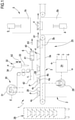
- FIG. 1 is a schematic view of a packaging apparatus in accordance with the present invention in which a film is unwound from a reel and precut into a sheet outside a packaging station of the same apparatus, where the sheet of film is heat sealed on the support;
- FIGS. 2 to 4 are schematic views of embodiment variants of a packaging apparatus in accordance with the present invention in which a film is supplied—starting from a reel—to a packaging station of the same apparatus where the film is heat sealed on the tray and cut into separate sheets;
- FIGS. 5 a to 5 j are further views of a packaging apparatus in accordance with the present invention schematized in different operating conditions and exemplifyingly arranged for vacuum packaging a product in a tray of the type with base, lateral wall and upper flange;
- FIG. 5 k instead shows a packaging apparatus in accordance with the present invention, schematized exemplifyingly arranged for vacuum packaging a product on a flat support;
- FIGS. 6 to 10 are different representations of a support
- FIGS. 11A to 11D are schematic representations of a first embodiment of a penetrating tool of the packaging apparatus in accordance with the present invention.
- FIG. 12 is a schematic representation of the penetrating tool, in accordance with FIGS. 11A-11D , arranged in an advanced position in which it cooperates with a base wall or lateral wall of a support;
- FIG. 12A is a schematic view in section of the penetrating tool, in accordance with FIGS. 11A-11D , arranged in an advanced position in which it cooperates with a base wall or lateral wall of a support;
- FIGS. 13A to 13D are schematic representations of a second embodiment of a penetrating tool of the packaging apparatus in accordance with the present invention.
- FIG. 14 is a schematic representation of the penetrating tool, in accordance with FIGS. 13A-13D , arranged in an advanced position in which it cooperates with a base wall or lateral wall of a support,
- FIG. 14A is a schematic view in section of the penetrating tool, in accordance with FIGS. 13A-13D , arranged in an advanced position in which it cooperates with a base wall or lateral wall of a support;
- FIG. 15 is a schematic view of a further embodiment variant of a packaging apparatus in accordance with the present invention.
- upstream and downstream refer to an advancement direction of a tray along an advancement path which extends from a starting station of the tray, through a packaging station and then up to a package unloading station.
- the product it is intended an article or a composite of articles of any type.
- the product can be of food type and be in the solid or liquid state or in gel form, i.e. in the form of two or more of the aforesaid states of aggregation.
- the product can comprise meat, fish, cheese, treated meat, ready-to-eat meals and frozen food of various type.
- control unit set to control the operations initiated by the apparatus.
- control unit it is intended a component of electronic type which can comprise at least one of the following: a digital processor (CPU), a memory (or memories), a circuit of analogue type, or a combination of one or more digital processing units with one or more circuits of analogue type.
- the control unit can be “configured” or “programmed” for executing several steps: in practice this can be made with any means that allow configuring or programming the control unit.
- one or more programs can be stored in appropriate memory banks connected to the CPU or to the CPUs; the program or programs contain instructions which, when executed by the CPU or by the CPUs, program or configure the control unit to execute the operations described in relation to the control unit.
- the control unit is or comprises circuitry of analogue type, then the circuit of the control unit can be designed to include circuitry configured, during use, for processing electrical signals in a manner such to execute the steps relative to the control unit.
- the term support identifies both a support element that is substantially flat, in particular lacking lateral walls, adapted to essentially define a flat base for the abutment of one or more products, and a tray comprising at least one base—for example substantially flat or convex—and at least one lateral wall emerging from the external perimeter of the base to define a container that is open at least at the top; the tray defines a volume in which the product can be housed.
- the tray can also comprise an upper edge portion emerging radially from a free edge of the lateral wall opposite the base: the upper edge portion emerges from the lateral wall according to a direction that is exiting with respect to the volume of the tray itself.
- the support can have a base with perimeter having rectangular, rhomboidal, circular or elliptical form.
- the support can be formed by means of a specific and separate manufacturing process or it can be made in line with a packaging process (packaging process).
- the support can be at least partly made of paper material.
- paper material it is intended paper or cardboard; in particular, the sheet material usable for making the support can have a basis weight comprised between 50 and 600 g/m 2 , in particular comprised between 100 and 500 g/m 2 , still more particularly between 150 and 400 g/m 2 .
- the paper material in question extends between a first and a second main extension surface.
- the sheet paper material employed for making the support can, in an embodiment variant thereof, be covered for at least one part of the first and/or second main extension surface by means of a plastic material covering, for example a film for food use. If the covering is arranged so as to cover at least part of the first main extension surface, the same covering will come to define an internal surface of the support.
- the covering is arranged on the second main extension surface, the same covering will come to define an external surface of the support.
- the covering can also be thermally treated in a manner so to be able to act as an element for engaging and fixing portions of the support, as will be better described hereinbelow.
- the covering can also be employed in order to define a kind of barrier to water and/or to humidity useful for preventing the weakening and the loss of structure of the support, with consequent uncontrolled deformation of the paper material constituting the latter component.
- the covering can be applied to the paper material (as specified above on the internal and/or external side of the support) in the form of a so-called “coating” or lacquer of thickness generally comprised between 20 and 400 ⁇ m, in particular between 30 and 200 ⁇ m, still more particularly between 30 and 80 ⁇ m.
- the covering can comprise a polythene-coating on one or both (internal and/or external side) sides of the paper material defining the support with thickness values that can for example vary between 20 and 400 ⁇ m, in particular between 30 and 200 ⁇ m, still more particularly between 30 and 80 ⁇ m, of covering material (i.e. polythene).
- the plastic covering material can for example be selected from among the following materials: LDPE, HDPE, PP, PE, polyesters, PVdC.
- the support can alternatively be at least partly made of single-layer or multilayer thermoplastic material. Preferably, the support is provided with barrier properties against gas. As used herein, such term refers to a film or sheet of material which has an oxygen transmission speed lower than 200 cm 3 /m 2 -day-bar, preferably lower than 150 cm 3 /m 2 -day-bar, still preferably lower than 100 cm 3 /m 2 -day-bar when measured in accordance with ASTM D-3985 at 23° C. and 0% relative humidity.
- Gas-barrier materials suitable for single-layer thermoplastic containers are for example polyesters, polyamides and the like.
- the support is made of a multilayer material comprising at least one gas barrier layer and at least one weldable layer in order to allow the welding of the covering film to the surface of the support.
- the gas barrier polymers that can be employed for the gas barrier layer are PVDC, EVOH, polyamides, polyesters and mixtures thereof.
- PVDC is any vinylidene chloride copolymer in which a greater quantity of the copolymer comprises vinylidene chloride and a lower quantity of the copolymer comprises one or more unsaturated monomers that can be copolymerized therewith, typically vinyl chloride and alkyl acrylates or methacrylates (e.g. methylacrylate or methacrylate) and mixtures thereof in different proportions.
- a barrier layer made of PVDC will contain plasticizing and/or stabilizing agents as known in the art.
- EVOH includes ethylene-vinylacetate copolymers, saponified or hydrolyzed, and refers to ethylene/vinyl alcohol copolymers having an ethylene co-monomer content preferably composed of a percentage between about 28 and about 48 mole %, more preferably between about 32 and about 44 mole %, of ethylene, and a saponification level of at least 85%, preferably at least 90%.
- polyamides is intended to indicate homo- and co- or ter-polymers. This term specifically includes aliphatic polyamides or co-polyamides, for example polyamide 6, polyamide 11, polyamide 12, polyamide 66, polyamide 69, polyamide 610, polyamide 612, copolyamide 6/9, copolyamide 6/10, copolyamide 6/12, copolyamide 6/66, copolyamide 6/69, aromatic and partially aromatic polyamides or copolyamides, such as polyamide 61, polyamide 6I/6T, polyamide MXD6, polyamide MXD6/MXDI, and mixtures thereof.
- polyesters refers to polymers obtained from the polycondensation reaction of dicarboxylic acids with dihydroxylic alcohols.
- Suitable dicarboxylic acids are for example terephthalic acid, isophthalic acid, 2,6-naphthalene dicarboxylic acid and the like.
- Suitable dihydroxylic alcohols are for example ethylene glycol, diethylene glycol, 1,4-butanediol, 1,4-cyclohexanedimethanol and the like.
- useful polyesters include poly(ethylene terephthalate) and copolyesters obtained by means of reaction of one or more carboxylic acids with one or more dihydroxylic alcohols.
- the thickness of the gas barrier layer will preferably be set in order to supply the material constituting the support with an oxygen transmission speed at 23° C. and 0% relative humidity lower than 50, preferably lower than 10 cm 3 /m 2 ⁇ d ⁇ atm, when measured in accordance with ASTM D-3985.
- the weldable layer will be selected from among polyolefins, such as ethylene homo- or co-polymers, propylene homo- or co-polymers, ethylene/vinylacetate co-polymers, ionomers and homo- or co-polyesters, e.g. PETG, a polyethylene terephthalate modified with glycol.
- polyolefins such as ethylene homo- or co-polymers, propylene homo- or co-polymers, ethylene/vinylacetate co-polymers, ionomers and homo- or co-polyesters, e.g. PETG, a polyethylene terephthalate modified with glycol.
- the term “copolymer” indicates a polymer derived from two or more types of monomers and includes terpolymers.
- the ethylene homo-polymers include high-density polyethylene (HDPE) and low-density polyethylene (LDPE).
- Ethylene copolymers include ethylene/alpha-olefin copolymers and ethylene/unsaturated ester copolymers.
- the ethylene/alpha-olefin copolymers generally include ethylene copolymers and one or more co-monomers selected from alpha-olefin having between 3 and 20 carbon atoms, such as 1-butene, 1-pentene, 1-hexene, 1-octene, 4-methyl-1-pentene and the like.
- the ethylene/alpha-olefin copolymers generally have a density in the interval between about 0.86 and about 0.94 g/cm 3 . It is generally intended that the term linear low-density polyethylene (LLDPE) includes that group of ethylene/alpha-olefin copolymers which fall within the density interval between about 0.915 and about 0.94 g/cm 3 and in particular between about 0.915 and about 0.925 g/cm 3 . Sometimes, the linear polyethylene in the density interval between about 0.926 and about 0.94 g/cm 3 is indicated as linear medium-density polyethylene (LMDPE).
- LLDPE linear low-density polyethylene
- the ethylene/alpha-olefin copolymers with lower density can be indicated as very-low-density polyethylene (VLDPE) and ultra-low-density polyethylene (ULDPE).
- VLDPE very-low-density polyethylene
- ULDPE ultra-low-density polyethylene
- the ethylene/alpha-olefin copolymers can be obtained with heterogeneous or homogeneous polymerization processes.
- Another useful ethylene copolymer is a ethylene/unsaturated ester copolymer, which is the copolymer of ethylene and one or more monomers of unsaturated esters.
- Useful unsaturated esters include vinyl esters of aliphatic carboxylic acids, in which the esters have between 4 and 12 carbon atoms, such as vinylacetate, and acrylic or methacrylic acid alkyl esters, in which the esters have between 4 and 12 carbon atoms.
- the ionomers are copolymers of an ethylene and an unsaturated mono-carboxylic acid having the carboxylic acid neutralized by a metal ion, such as zinc, or preferably sodium.
- Useful propylene copolymers include propylene/ethylene copolymers, which are propylene and ethylene copolymers having a percentage content by weight with majority propylene and propylene/ethylene/butene ter-polymers, which are copolymers of propylene, ethylene and 1-butene.
- Additional layers such as adhesive layers, for example in order to make the gas barrier layer better adhere to the adjacent layers, can preferably be present in the material constituting the support and are selected on the basis of the specific resins used for the gas barrier layer.
- the multilayer material used for forming the support can comprise (from the outermost layer to the layer of contact with the more internal foods) one or more structural layers, typically made of a material such as polystyrene foam, polyester foam or polypropylene foam, or cardboard, or cast sheet for example of polypropylene, polystyrene, poly(vinylchloride), polyester; a gas barrier layer and a weldable layer.
- An easy-to-open breakable layer can be positioned adjacent to the weldable layer in order to facilitate the opening of the final packaging.
- Mixtures of polymers with low cohesive resistance which can be used as breakable layer are for example those described in the document WO99/54398.
- the overall thickness of the support will typically but not exclusively be up to 5.00 mm, preferably it will be comprised between 0.04 and 3.00 mm and more preferably between 0.05 and 1.50 mm, still more preferably between 0.15 and 1.00 mm).
- the support can be entirely made of paper material (optionally, covering made of plastic material film) or it can be entirely made of plastic material.
- the support is at least partly made of paper material and at least partly of plastic material; in particular, the support is internally made of plastic material and at least partly externally covered in paper material.
- the support can be at least partly made of metallic material, in particular made of aluminum.
- the support can also be made at least partly of aluminum and at least partly of paper material.
- the support can be made of at least one of the following materials: metal, plastic, paper.
- a film can be applied to the supports or trays so as to make a fluid-tight package housing the product.
- the film applied to the support is typically a flexible multilayer material comprising at least one first external weldable layer capable of being welded to the internal surface of the support, optionally a gas barrier layer and a second heat-resistant external layer.
- the polymers used in said multilayer material must be easily formable since the film must be taut and softened by the contact with the heating plate before being laid on the product and the support.
- the film must be laid on the product, being adapted to its shape and possibly to the internal shape of the support.
- the weldable external layer can comprise any polymer capable of being welded to the internal surface of the support.
- Polymers suitable for the weldable layer can be ethylene homo- and co-polymers, such as LDPE, ethylene/alpha-olefin copolymers, ethylene/acrylic acid copolymers, ethylene/methacrylic acid ethylene/vinylacetate copolymers or copolymers, ionomers, co-polyesters, e.g. PETG.
- Preferred materials for the weldable layer are LDPE, ethylene/alpha-olefin copolymers, e.g. LLDPE, ionomers, ethylene/vinylacetate copolymers and mixtures thereof.
- the film can comprise a gas barrier layer.
- the gas barrier layer typically comprises oxygen-impermeable resins such as PVDC, EVOH, polyamides and mixtures of EVOH and polyamides.
- the thickness of the gas barrier layer is set in a manner so as to provide the film with an oxygen transmission speed at 23° C. and 0% relative humidity lower than 100 cm 3 /m 2 ⁇ d ⁇ atm, preferably lower than 50 cm 3 /m 2 ⁇ d ⁇ atm, when measured in accordance with ASTM D-3985.
- Common polymers for the heat-resistant external layer are for example ethylene homo- or co-polymers, ethylene/cyclic olefin copolymers, such as ethylene/norbornene copolymers, propylene homo- or co-polymers, ionomers, polyesters, polyamides.
- the film can also comprise other layers such as adhesive layers, filling layers and the like in order to supply the necessary thickness to the film and to improve its mechanical properties, such as puncture resistance, abuse resistance, formability and the like.
- the film is obtained by means of any suitable co-extrusion process, through an extrusion head with flat or circular opening, preferably by means of co-extrusion or by means of hot blowing.
- the film is substantially non-oriented.
- the film, or only one or more of its layers is crosslinked in order to improve, for example, the force of the film and/or the heat resistance when the film is brought into contact with the heating plate during the vacuum skin-pack packaging process.
- the crosslinking can be obtained by means of use of chemical additives or by subjecting the film layers to energy radiation treatment, such as treatment with high-energy electron beam, in order to induce the crosslinking between molecules of the irradiated material.
- Films suitable for this application have a thickness in the interval between 50 and 200 micrometers, between 70 and 150 micrometers.
- Films suitable for use as film in a vacuum skin-pack packaging process are for example those sold by Cryovac® with the commercial names TS201®, TH300®, VSTTM0250, VSTTM0280.
- Reference number 1 overall indicates a packaging apparatus for packaging a product P arranged on a support 4 , for example on a flat support or on a tray provided with lateral wall.
- the apparatus 1 is for example configured for the vacuum packaging of the product in which a thin film of plastic material is arranged on the product and closely adheres at least to an upper edge of the support, to the upper or internal surface of the support not occupied by the product, as well as to the surface of the product thus leaving a minimal quantity of residual air inside the package.
- the apparatus 1 can also be used for forming controlled atmosphere in a package from which air has been previously removed.
- the apparatus 1 comprises a frame 2 , a transport group 25 brought by the frame 2 and configured for moving the support 4 along a pre-set operating path from a station 26 for loading preformed supports (e.g. see FIG. 1 ) or from a station 27 for forming supports (e.g. see FIG. 4 ) towards a packaging station 5 .
- the transport group 25 can for example comprise a sliding surface 28 , normally horizontal, and a conveyor 3 associated with the sliding surface 28 in order to move the supports 4 along the pre-set advancement path, in particular in the horizontal direction indicated by the arrow A 1 shown in FIG. 1 .
- the conveyor 3 is configured for moving a pre-set number of supports 4 each time along the advancement path until they are positioned inside a packaging station 5 where the supports 4 are coupled with respective film portions 6 .
- a control unit 24 can control the conveyor 3 in order to move a pre-set number of supports 4 from a region outside the packaging station 5 to a region inside the packaging station 5 where the supports are situated vertically aligned with respective film portions 6 .
- the conveyor 3 can, for example, comprise a first transfer device 3 a (for example the conveyor belt shown in FIGS. 1-4 ) configured for bringing the supports 4 in proximity to the packaging station and a second transfer device 3 b (schematically represented in FIGS. 1-4 ) adapted to pick up one or more of said supports 4 and bring them into the packaging station 5 .
- the second transfer device 3 b can for example include arms or other devices active on the supports 4 and capable of collecting a pre-set number of such supports 4 from the first transfer device 3 a , bring them into the packaging station 5 in order to then return towards the first transfer device 3 a and pick up a successive series of supports 4 .
- the conveyor 3 can include pushers (e.g., in the form of bars that extend transverse to said direction A 1 ) active on the supports 4 and capable of sequentially pushing pre-set series of supports inside the packaging group 5 .
- the pushers can be moved by chain or belts and can be moved to the interior of the packaging station 5 in order to correctly position a pre-set number of supports, and then be retracted from the packaging station once the supports have reached the correct position inside the same packaging station.
- the conveyor 3 can include housings (for example in the form of plates provided with cavities shaped for receiving a pre-set number of supports) which are moved along said direction A 1 and which are moved inside the packaging station 5 together with the supports: according to the latter alternative, the housings are suitably shaped in order to be housed inside the packaging station during the application of the film to the support.
- housings for example in the form of plates provided with cavities shaped for receiving a pre-set number of supports
- the conveyor group 25 can also comprise at least one motor member 29 , for example a stepper motor group or a system of actuators, for driving the conveyor 3 and conferring a stepping movement to the supports 4 .
- at least one motor member 29 for example a stepper motor group or a system of actuators, for driving the conveyor 3 and conferring a stepping movement to the supports 4 .
- the products P can be positioned on the or in the support 4 either manually or due to a suitable product loading device.
- the loading of the product onto or into the respective support 4 can occur upstream of the loading station 26 , at the loading station 26 , or in any position between the loading station 26 and the packaging station 5 ; otherwise, in the case of FIG. 4 (in-line forming of the support) the positioning of the product P on the support occurs downstream of the forming station 27 , in any one position between the forming station 27 and the packaging station 5 .
- the apparatus 1 also comprises a group 30 for feeding a film, in particular a plastic material film of the above-described type intended to be coupled with the support 4 .
- the film feeding group 30 can for example comprise a feeding roller 31 supported by a respective support structure, for example comprising one or more uprights in turn carried by the frame 2 .
- the film feeding group 30 can be configured for forming a plurality of discrete sheets upstream of the packaging station (see once again the example of FIG.
- the feeding group 30 comprises a film cutting unit 32 for the film which, starting from a continuous web, is transversely cut and, optionally, also longitudinally cut, in a manner so as to form film portions 6 or a plurality of discrete sheets 6 of pre-set size that are then sent to the packaging station 5 , as will be described hereinbelow in greater detail.
- the film cutting unit 32 comprises a cutting device with a blade 33 and an actuator 34 .
- actuator 34 can be any one type of electrical, pneumatic or hydraulic actuator.
- the actuator 34 is preferably fixed to the frame 2 and is connected to the cutting device so as to push and pull the blade 33 in a direction transverse to the unrolled film portion, as indicated by the double arrow A 2 of FIG. 1 .
- the feeding group 30 can be configured for unwinding the plastic film from the feeding roller 31 , suitably guiding it and sending it in the form of continuous web to the packaging station 5 (this alternative is for example shown in FIGS. 2-4 ).
- the cutting of the film 6 can occur after the film 6 has been fixed to the support 4 and/or after the step of removal or modification of the gas inside the support 4 has been completed.
- the packaging station 5 is configured for fixing a film portion 6 to said supports 4 and comprises a lower tool 5 b and an upper tool 5 c .
- the lower tool 5 c has internal walls 35 defining a pre-set number of positioning seats 5 a of the supports 4 .
- the lower tool 5 b is provided with multiple positioning seats 5 a : each seat 5 a is arranged for housing a corresponding support 4 ; in this case the upper tool 5 c is provided with one or more retention structures 36 for retaining the film 6 above the support or supports 4 present in the respective positioning seats 5 a.
- a lower tool 5 b is shown that is provided with a seat 5 a for receiving a respective support (illustrated in a non-limiting manner in the embodiments of FIGS. 5 a -5 j are trays 4 with lateral wall, while in FIG. 5 k the embodiment is represented in which the support has flat shape) and an upper tool 5 c comprises a retention structure 36 , for example plate-shaped, intended to position a film portion 6 above and aligned with the support 4 present in said seat 5 a.
- a retention structure 36 for example plate-shaped
- the support 4 is a tray having a base 4 a abutting against a movable plate 37 present in each positioning seat 5 a of the lower tool 5 b and a lateral wall 4 b emerging from base 4 a : the tray 4 is received in the positioning seat 5 a so that an annular flange 4 c of the tray 4 emerging from an upper edge of the lateral wall 4 b can abut above an end surface 38 of the wall defining said seat 5 .
- the flat support 4 is positioned in a positioning seat 5 a suitably shaped in the lower tool 5 b .
- the upper and lower tools cooperate in order to define a housing chamber T: in a first operating condition of the packaging station 5 —shown in FIGS. 1-4 and 5 a , 5 b —the upper and lower tools are spaced from each other and the housing chamber T is opened, enabling the movement of successive film portions inside the housing chamber.
- a second operating condition of the packaging station shown in FIGS. 5 c -5 k —the housing chamber T is hermetically closed with respect to an atmosphere outside the apparatus 1 . It is observed that by hermetically closed it is intended that the housing chamber cannot freely communicate with the environment outside the chamber itself and that therefore gas can be supplied or extracted from the packaging chamber T only by means of feeding or suctioning channels 23 under the control of the apparatus 1 .
- the retention structure 36 has an active surface 39 (for example flat as in the embodiments or dome-shaped) intended for contact with the film portion 6 placed above the lower tool 5 c .
- the upper tool is provided with a heating device (not illustrated since per se known) configured for heating the active surface 39 of the retention structure 36 in a manner so as to confer the desired deformability characteristics to the film 6 : in accordance with the cases, a heating device can be provided that is configured for heating the entire active surface of the retention structure or only part thereof (for example a central portion and/or a perimeter portion).
- the retention structure 36 also provides for a retention system of mechanical type (for example using grippers active on the perimeter edges of the film portion) or of vacuum type comprising a plurality of openings distributed on the active surface that are part of a suctioning system controlled by the control unit 24 so as to generate a suction effect and retain the film portion against the active surface at least during one part of the packaging process.
- a retention system of mechanical type for example using grippers active on the perimeter edges of the film portion
- vacuum type comprising a plurality of openings distributed on the active surface that are part of a suctioning system controlled by the control unit 24 so as to generate a suction effect and retain the film portion against the active surface at least during one part of the packaging process.
- the transfer of the film within the housing chamber occurs by means of movement of the film in continuous film form: for example, if the film is cut after the packaging, such film can be driven by systems operating downstream of the packaging station.
- film driving systems can be provided that are active on the longitudinal edges thereof: chains are commonly used with active grippers on the edges of the film.
- the apparatus 1 can comprise a transfer device 40 (see FIG. 1 ) configured for picking up the sheets cut by the cutting unit 32 and positioning the film sheets inside the packaging station 5 and above the respective support 4 .
- the transfer device 40 can for example comprise a support structure 41 having a flat or slightly convex holding surface adapted to receive the at least one or more sheets of film from the cutting unit 32 :
- FIG. 1 shows that the blade 33 has intercepted the continuous film and a film sheet 6 is positioned at the holding surface.
- the support structure 41 can hold the cut film sheet by using one or more of the following systems:
- the transfer device 40 also comprises a mechanism 42 , for example carried by the frame 2 , active on the support structure 41 and configured for moving the support structure with respect to the packaging station between a first position, in which the support structure 41 is positioned at the cutting unit 32 , for example immediately downstream of the blade 33 , and at least one second position, in which the support structure 41 is positioned inside the packaging station 5 .
- the mechanism comprises an active transfer actuator on the support structure in order to move such structure between said first and second position: for example, the transfer actuator can move the support structure along a direction parallel to said horizontal direction A 1 as indicated by the double arrow A 3 in FIG. 1 .
- the transfer actuator can be an electrical, pneumatic or hydraulic actuator.
- the upper tool can be made movable with respect to the frame 2 and be configured for collecting the cut film sheets at the cutting unit.
- the transfer device 4 includes a mechanism, for example carried by the frame, configured for moving the upper tool between a first position, in which the upper tool is positioned at the support structure in order to pick up one or more film sheets from the support structure, and at least one second position, in which the upper tool is aligned with the lower tool and configured for positioning at least one film sheet above the respective support 4 .
- the apparatus 1 also comprises a suctioning system or vacuum device 21 connected to the housing chamber T and configured for the removal of gas from inside said chamber.
- the suctioning system 21 comprises at least one vacuum pump 22 and at least one suctioning channel 23 which connects the interior of said chamber T to the pump 22 ; the control unit 24 controls the pump 22 in order to draw gas from said housing chamber T, at least when the packaging station 5 is in said second operating condition, i.e. with said housing chamber T hermetically closed.
- the apparatus 1 can also comprise a controlled atmosphere generation device connected to the housing chamber and configured for injecting a gas current in said chamber;
- the controlled atmosphere generation device comprises at least one injection pump and/or an injection valve which acts on at least one injection tube configured for placing the interior of said housing chamber in communication with a gas source (non shown) which can, alternatively, be situated at a distance from the apparatus 1 ;
- the control unit 24 can be configured for controlling the opening and the closing of the injection valve (or the activation of the injection pump) and injecting said gas current at least when the packaging station is in said second operating condition, i.e. with said housing chamber hermetically closed.
- the control unit 24 can also be configured for controlling the composition of the modified atmosphere generated inside the chamber T.
- the control unit 24 can regulate the composition of the gas flow injected into the housing chamber.
- the composition of the gas injected into the housing chamber for generating a modified atmosphere can vary in accordance with the nature of the product P.
- modified atmosphere mixtures include a volumetric quantity of one or more of N 2 , O 2 and CO 2 which is different from the quantity of these same gases in 20° C. atmosphere and at sea level (1 atmosphere pressure).
- the apparatus 1 finally comprises at least one penetrating tool 8 associated with the packaging station 5 .
- the packaging station 5 is configured for:
- the penetrating tool 8 is arranged at least partly inside the packaging station and is suitable to operate at the reception volume.
- the penetrating tool 8 is movable relative to the positioning seat 5 a by means of an actuator 8 a —for example an electrical, hydraulic or pneumatic actuator—at least between a receded position and an advanced position.
- an actuator 8 a for example an electrical, hydraulic or pneumatic actuator—at least between a receded position and an advanced position.
- the penetrating tool 8 In the receded position, the penetrating tool 8 is arranged outside the reception volume and is spaced or at most in contact with the base wall or with the lateral wall of the support 4 .
- the penetrating tool 8 is also configured to be arranged in the advanced position in which a part of the tool 8 crosses the base wall or the lateral wall of a support 4 arranged in said positioning seat 5 a , accessing the reception volume for the product P.
- a penetrating tool 8 has been illustrated, adapted to cross through a lateral wall 4 b or a base wall 4 a of a tray-shaped support 4 . Nevertheless, it is possible to use a support 4 comprising a flat element (see FIG. 5 k ) essentially having a base wall.
- the penetrating tool 8 has at least one first through opening 11 a and at least one second through opening 11 b distinct and separate from each other.
- through opening it is intended an opening which places the interior volume of the penetrating tool 8 in fluid communication with a volume outside the tool 8 , for example with the volume of the housing chamber T.
- the position of the first through opening and of the second through opening with respect to the wall of the support traversed by the same penetrating tool is as follows:
- FIGS. 12, 12A and 14 a configuration is schematized of the penetrating tool 8 arranged in the advanced position in which the openings 11 a , 11 b are arranged astride a wall (base wall or lateral wall) of the support 4 .
- the second through opening 11 b in the advanced position of the penetrating tool 8 —partly extends into the reception volume, beyond said base wall or beyond said lateral wall, and partly outside said reception volume.
- the penetrating tool 8 can be connected to a suctioning system 21 which allows, by means of said openings 11 a and 11 b , air suction from a housing chamber C for the product defined by the cooperation of the support 4 with the film portion 6 .
- the penetrating tool 8 can be connected to a gas injection system adapted to supply a pre-set quantity of a gas to the housing chamber C for the product P, if after having removed ambient air it is desired to create a package in controlled atmosphere.
- the penetrating tool 8 comprises a distal portion 9 which—in the advanced position of the penetrating tool 8 —is suitable to be arranged at least partly in the reception volume: the first and the second through opening 11 a , 11 b are defined at said distal portion 9 .
- the distal portion 9 has an elongated shape and extends along a main extension direction; such distal portion 9 comprises:
- At least the front portion 10 and the intermediate portion 11 are joined as a single piece to define a single body; advantageously, the entire distal portion 9 is made as a single piece.
- the front portion 10 is arranged in the reception volume while the intermediate portion 11 is arranged astride the base wall or lateral wall of the support 4 .
- the intermediate portion 11 in the advanced position of the penetrating tool 8 —is partly arranged in the reception volume, beyond the base wall or beyond the lateral wall, and partly outside said volume.
- the intermediate portion 11 has a pre-set longitudinal extension defined along the main extension direction of the distal portion 9 ; in the advanced position of the penetrating tool 8 , the base wall or lateral wall of the support 4 is situated at a central zone or centerline of the intermediate portion 11 .
- the first through opening may extended over the entire extension of the front portion 10 and of the intermediate portion 11 .
- the first through opening 11 a is delimited by a closed continuous edge comprising:
- Said sections confer to the closed continuous edge a shape that is non-planar and extended along the longitudinal extension of the penetrating tool 8 (e.g. see FIGS. 11D and 13D ).
- the first through opening 11 a is defined by a single opening perimetrically delimited by the closed continuous edge.
- the second through opening 11 b instead extends over the entire longitudinal extension of the intermediate portion 11 and along at least part of the entire longitudinal extension of the front portion 10 .
- the second through opening 11 b is defined by a single opening perimetrically delimited by a single closed continuous edge, for example having elliptical elongated shape extending parallel to the main extension direction of the distal portion 9 .
- the first and the second through opening 11 a , 11 b are optionally arranged on mutually opposed sides of the penetrating tool 8 .
- the intermediate portion 11 has—according to a section defined at the first through opening 11 a and transverse to the main extension direction of the distal portion 9 —an open profile, optionally shaped substantially C-shaped or U-shaped.
- the intermediate portion 11 comprises (e.g. see FIGS. 11A and 13A ):
- the first and the second lateral wall 14 , 15 have—on the opposite side with respect to the base 13 —respective free edges 14 a , 15 a at least partly delimiting the first through opening 11 a.
- the first lateral wall and the second lateral wall emerge from said base 13 and extend from the latter for a same height h.
- the base 13 of the intermediate portion 11 is flat, and the free edges of the first and second lateral wall 14 , 15 are defined on a single plane parallel to the base 13 .
- the free edges of the first and second lateral walls 14 , 15 extend along respective directions parallel to each other, optionally parallel to the main extension direction of the distal portion 9 , to define said second and third section of the closed continuous edge of the first through opening 11 a.
- the first lateral wall 14 of the intermediate portion 11 has—according to a section transverse to the main extension direction of the distal portion 9 —an arched profile.
- the second lateral wall 15 of the intermediate portion 11 has—according to a section transverse to the main extension direction of the distal portion 9 —an arched profile.
- the concavities defined by the respective first and second lateral wall 14 , 15 are facing each other.
- the base 13 With regard to the base 13 , the latter—in a preferred but non-limiting embodiment of the invention—is extended along a plane and has a substantially rectangular shape.
- the second through opening 11 b is defined on the base 13 and extends along the entire longitudinal extension of the latter.
- the distal portion 9 comprises a free cutting edge 16 configured to enable the perforation of the base wall or lateral wall of the support 4 during the relative movement of the tool 8 , with respect to the positioning seat 5 a , from the receded position to the advanced position, defining a hole 4 d on said wall of the support 4 .
- the same portion 9 essentially defines a perforating tool configured for making—during the movement of the tool 8 —the hole 4 d on the support.
- the hole 4 d represents the passage of the support through which the distal portion passes in order to arrange—in the advanced position of the tool 8 —at least part of the first and second through opening 11 a , 11 b in the reception volume.
- the free cutting edge 16 is essentially defined by the first section of the closed continuous edge: the free cutting edge defines an open profile connected without interruption to the second and third section. As is visible from the enclosed figures, the free cutting edge 16 is defined exclusively on the front portion 10 of the distal portion 9 defining said first section: on the other hand, the second, third and fourth sections of the closed continuous edge are not sharp/cutting and essentially have the function of maintaining the hole open, ensuring that the one or more flaps possibly formed at the hole are maintained in open position.
- the front portion 10 comprises a base 17 , optionally flat, joined in a single piece to the base 13 of the intermediate portion 11 and emerging without interruption from the latter base 13 : the base 17 of the front portion 10 is terminally delimited by an end part of the free cutting edge 16 having a shape substantially V-shaped, C-shaped or U-shaped.
- the front portion 10 comprises a first lateral cutting wall 18 and a second lateral cutting wall 19 opposite each other and emerging from the base 17 of the same front portion 10 ; the first and the second lateral cutting wall 18 , 19 are joined as a single piece respectively as a continuation of the first and second lateral wall 14 , 15 of the intermediate portion 11 (e.g. see FIGS. 11D and 13D ).
- first and the second lateral cutting wall 18 , 19 are joined as a single piece to the base 17 , optionally flat, of the front portion 10 .
- Base 17 , first lateral cutting wall 18 and second lateral cutting wall 19 define—according to a view along the main extension direction of the distal portion 9 —a shape with substantially C-shaped or substantially U-shaped open profile.
- the free cutting edge 16 delimits without interruption the first lateral cutting wall 18 , the base 17 and the second lateral cutting wall 19 of the front portion 10 .
- the free cutting edge 16 is joined without interruption to the respective free edges of the first and the second lateral wall 14 , 15 of the intermediate portion 11 .
- the free cutting edge 16 delimits the first and the second lateral cutting wall 18 , 19 ; the free edges of the first and second lateral wall 14 , 15 of the intermediate portion 11 are arranged at a pre-set distance d smaller than a maximum distance w between the free cutting edges of the first and second lateral cutting wall 18 , 19 of the front portion 10 .
- the penetrating tool 8 lacks sharp/cutting portions: in other words, the penetrating tool does not have elements adapted to define a passage opening on the support for the crossing of the distal portion 9 , since the opening or openings are made in the support in steps preceding the step of suctioning gas from the housing chamber.
- the distal portion essentially comprises a penetration element lacking cutting elements; the apparatus 1 may therefore provide for such configuration of the penetrating tool 8 , a perforation station 43 placed upstream of the packaging station 5 with respect to an advancement direction of the supports 4 (A 1 in FIG. 1 ); the perforation station is configured for making one or more through openings or holes 4 d on the supports 4 , through which the distal portion 9 —lacking cutting elements—can pass in order to reach the reception volume for the product.
- the packaging station 5 is configured for sealingly constraining the film portion 6 to the support 4 in order to define a housing chamber C for the product P.
- the suctioning system 21 is associated with the penetrating tool 8 and is configured for removing air—through the first and second through opening 11 a , 11 b in the advanced position of the penetrating tool 8 —both from the reception volume and, once the housing chamber is formed, also from the housing chamber C, thereby the maximum formation of vacuum is ensured, and consequently the film portion can closely adhere to the product P and to the upper surface of the support, forming an actual hermetic closure skin for the product on the support.
- the penetrating tool 8 is suitable to operate inside said housing chamber T and to cooperate with one or more supports engaged in the seat 5 a of the station 5 .
- the suctioning system 21 comprises:
- the first and the second through opening 11 a , 11 b in advanced position condition of the penetrating tool 8 and in the second operating condition of the packaging station 5 —are in direct fluid communication with the housing chamber T and hence—through the suctioning channel 23 —with the vacuum pump 22 .
- the vacuum pump 22 upon control of the control unit 24 , is configured to enable the removal of air in the housing chamber C for the product P—through the first and second through openings 11 a , 11 b —by means of air suction from the housing chamber T of the packaging station 5 .
- the apparatus may comprise a control unit 24 ; such unit can be advantageously connected to the packaging station 5 and to the penetrating tool 8 .
- the control unit 24 is configured to:
- control unit 24 is configured to:
- the control unit (during or immediately after the end of the air suction from the housing chamber T and from the housing chamber C for the product—is configured to control the movement of the penetrating tool from the advanced position to the receded position so that the film portion can act on the opening flap 4 f and close the through opening or hole 4 d ( FIG. 10 ).
- a packaging method according to the invention is described hereinbelow.
- the method described herein preferably uses the above-described apparatus 1 claimed in one or more of the enclosed claims.
- the various method steps described hereinbelow can be carried out under the control of the control unit 24 , which acts on suitable actuators and/or motors and/or pumps and/or valves in order to achieve the various described steps and on one hand determine the movements of the various movable parts and on the other hand control the suction and/or the injection of gas from the/into the housing chamber.
- the packaging method according to the invention provides for moving one or more supports 4 on which at least one respective product P is arranged along the pre-set advancement path A, up to the packaging station 5 , as well as for moving at least one portion of a film 6 up to the same packaging station 5 : in order to enable the access of the film portions and of the supports in the packaging station, this is suitably maintained in the first operating condition in order to then be closed and brought into the second operating condition once the one or more supports and respective one or more film portions are suitably positioned in the packaging station.
- the control unit in addition to controlling the just-described movements suitably synchronizes the stepping motion of the trays, the stepping motion and the passage of the packaging station from the first to the second operating condition and vice versa.
- the packaging method provides for receiving at least one support 4 in the packaging station 5 , at a respective positioning seat 5 a , and receiving at least one portion of a film 6 which is arranged above and vertically aligned with said at least one support so that, between said support and said film portion, a reception volume is defined where said product P to be packaged is located.
- the method provides for positioning the penetrating tool 8 in the advanced position in which a part of the tool 8 crosses the base wall or the lateral wall of the support 4 arranged in said positioning seat, accessing the reception volume for the product.
- the step of positioning the penetrating tool in the advanced position comprises moving the penetrating tool from the receded position to the advanced position: during said movement the penetrating tool perforates the base wall or the lateral wall of the support, forming at least one hole 4 d through which the penetrating tool is arranged: at the hole 4 d , the penetrating tool can form one or more flaps 4 f , foldable and constrained to edge portions of the hole 4 d .
- the hole can have circular shape, triangular shape, polygonal shape, elliptical shape or still another shape in accordance with the geometry of the penetrating tool.
- such penetrating tool 8 has the first through opening arranged at least partly inside the reception volume for the product, beyond said base wall or beyond said lateral wall, and simultaneously has the second through opening arranged astride said base wall or said lateral wall.
- the packaging method then provides for, preferably upon control of the control unit 24 , the steps of extracting gas at least from the reception volume for the product through said first and said second opening, and of sealingly constraining the film portion 6 to said support 4 .
- the constraining step occurs for example by means of heat-welding the film to the respective support following a suitable heating of the film and/or of the support by the packaging station.
- the constraining step can alternatively occur via gluing, upon application of suitable adhesives at the zone of mutual contact between film and support.
- the step of constraining the film portion 6 to the support 4 comprises sealingly constraining the film portion with at least one perimeter edge of the support 4 in order to define a housing chamber C for the product P: for example, the film portion can adhere to the perimeter edge of the support and to the upper surface of the support not occupied by the product.
- the suctioning step provides for controlling the suctioning system 21 to remove air from said housing chamber C—through the first and second through opening 11 a , 11 b —also after having sealingly constrained the film portion to the perimeter edge of the support, in a manner such that the film can closely unite with the surface of the product and of the support, adhering to the latter like a skin.
- the penetrating tool 8 is associated with the packaging station 5 and is suitable to operate inside said housing chamber T: in particular the suction of gas from the housing chamber is carried out when such chamber is formed and hermetically closed, after having brought the upper tool and lower tool into said second operating condition.
- the penetrating tool is brought into the advanced position thereof in a manner such that the first and the second through opening 11 a , 11 b are in direct fluid communication with the housing chamber T and hence—through the suctioning channel 23 —with the vacuum pump 22 .
- the method provides for controlling the vacuum pump 22 and removing gas—through the first and second through opening 11 a , 11 b —also by suctioning air from said reception volume (when the film portion is not yet sealingly constrained with at least one perimeter edge of the respective support) and hence, upon fixing the film portion to the respective support, from the housing chamber C for the product, as stated leading to a maximization of the vacuum effect.
- the packaging method comprises the step of returning the penetrating tool into the receded position, enabling the film portion to adhere to a surface of the perforated lateral wall or base wall, hermetically sealing the hole 4 d .
- the possible one or more flaps 4 f are moved to close the hole 4 and in alignment with said base wall or said lateral wall of the support: in particular, the film portion adheres to a surface of said perforated lateral wall or base wall, also blocking said one or more flaps perfectly aligned with the respective wall to close the hole.
- the step of returning the penetrating tool into the receded position occurs after having sealingly constrained the film portion to the perimeter edge of the support and preferably once the gas extraction step has terminated. It should also be observed that the step of returning the penetrating tool into the receded position occurs after a pre-set period of time from the beginning of the suctioning step or upon reaching a pre-set vacuum level in the housing chamber (detectable by suitable pressure sensors present in the housing chamber and connected with the control unit).
Landscapes
- Mechanical Engineering (AREA)
- Engineering & Computer Science (AREA)
- Chemical & Material Sciences (AREA)
- Dispersion Chemistry (AREA)
- Fluid Mechanics (AREA)
- Physics & Mathematics (AREA)
- Composite Materials (AREA)
- Containers And Plastic Fillers For Packaging (AREA)
- Vacuum Packaging (AREA)
- Packages (AREA)
- Basic Packing Technique (AREA)
- Supplying Of Containers To The Packaging Station (AREA)
- Perforating, Stamping-Out Or Severing By Means Other Than Cutting (AREA)
Applications Claiming Priority (3)
| Application Number | Priority Date | Filing Date | Title |
|---|---|---|---|
| IT102016000103666A IT201600103666A1 (it) | 2016-10-14 | 2016-10-14 | Apparecchiatura e metodo di confezionamento di un prodotto |
| IT102016000103666 | 2016-10-14 | ||
| PCT/IB2017/056353 WO2018069880A1 (en) | 2016-10-14 | 2017-10-13 | Apparatus and method for packaging a product |
Publications (2)
| Publication Number | Publication Date |
|---|---|
| US20190241296A1 US20190241296A1 (en) | 2019-08-08 |
| US11230397B2 true US11230397B2 (en) | 2022-01-25 |
Family
ID=57960739
Family Applications (1)
| Application Number | Title | Priority Date | Filing Date |
|---|---|---|---|
| US16/339,882 Active 2038-01-06 US11230397B2 (en) | 2016-10-14 | 2017-10-13 | Apparatus and method for packaging a product |
Country Status (11)
| Country | Link |
|---|---|
| US (1) | US11230397B2 (it) |
| EP (1) | EP3526122B1 (it) |
| CN (1) | CN110573428B (it) |
| AU (1) | AU2017342228B2 (it) |
| ES (1) | ES2858425T3 (it) |
| IT (1) | IT201600103666A1 (it) |
| MX (1) | MX2019004093A (it) |
| NZ (1) | NZ752577A (it) |
| PT (1) | PT3526122T (it) |
| RU (1) | RU2743740C2 (it) |
| WO (1) | WO2018069880A1 (it) |
Cited By (1)
| Publication number | Priority date | Publication date | Assignee | Title |
|---|---|---|---|---|
| US11763703B2 (en) | 2021-11-03 | 2023-09-19 | Samsung Electronics Co., Ltd. | Electronic apparatus |
Families Citing this family (10)
| Publication number | Priority date | Publication date | Assignee | Title |
|---|---|---|---|---|
| IT201600103666A1 (it) * | 2016-10-14 | 2018-04-14 | Cryovac Inc | Apparecchiatura e metodo di confezionamento di un prodotto |
| WO2020058278A2 (de) * | 2018-09-17 | 2020-03-26 | Gea Food Solutions Germany Gmbh | Verpackungsmaschine zur herstellung einer flachskinverpackung |
| CN113165756B (zh) * | 2018-10-11 | 2023-03-28 | 克里奥瓦克公司 | 用于制作支撑件或包装的设备和工艺以及包装设备和工艺 |
| DE102018221629A1 (de) * | 2018-12-13 | 2020-06-18 | Multivac Sepp Haggenmüller Se & Co. Kg | Verfahren zum Verpacken von Produkten und Verpackungsmaschine |
| DE102019103196A1 (de) * | 2019-02-08 | 2020-08-13 | Buergofol GmbH | Unterwerkzeug für eine Skin-Verpackung |
| GB202001133D0 (en) * | 2020-01-27 | 2020-03-11 | Ishida Europe Ltd | Container sealing apparatus and method of sealing |
| WO2021190721A1 (en) * | 2020-03-23 | 2021-09-30 | Cryovac, Llc | Packaging apparatus and process |
| CN112810869A (zh) * | 2021-02-05 | 2021-05-18 | 福建省聚元食品股份有限公司 | 牛排包装机 |
| TWI796680B (zh) * | 2021-04-29 | 2023-03-21 | 宏洋精密工業股份有限公司 | 塑膠部品封包方法及其裝置 |
| IT202300000867A1 (it) * | 2023-01-20 | 2024-07-20 | G Mondini S P A | Metodo ed apparato per il confezionamento di almeno un prodotto e relativa confezione |
Citations (16)
| Publication number | Priority date | Publication date | Assignee | Title |
|---|---|---|---|---|
| GB1416101A (en) | 1972-04-26 | 1975-12-03 | Librawerk Pelz & Nagel Kg | Method and apparatus for removing gas from a flexible container filled with powdered or granular material |
| US4162599A (en) * | 1978-06-19 | 1979-07-31 | C. A. Pemberton & Co. Limited | Vacuum packaging |
| US5025611A (en) * | 1985-11-14 | 1991-06-25 | Garwood Ltd. | Thermoplastic skin packing means |
| US5419101A (en) * | 1994-09-22 | 1995-05-30 | World Class Packaging Systems, Inc. | Gas exchange manifold |
| US5491957A (en) | 1994-04-06 | 1996-02-20 | Maskell; Richard | Method and device for evacuating gas tight envelope |
| US20060147588A1 (en) * | 1997-03-13 | 2006-07-06 | Case Ready Solutions Llc | Products, methods and apparatus for fresh meat processing and packaging |
| US20060191594A1 (en) | 2000-02-11 | 2006-08-31 | Daniel Py | Device with needle penetrable and laser resealable portion and related method |
| US20120204516A1 (en) * | 2009-07-29 | 2012-08-16 | Cryovac, Inc. | Vacuum Skin Packaging of a Product Arranged on a Support |
| US20130016924A1 (en) | 2009-12-17 | 2013-01-17 | John Helmsderfer | Vacuum clip for storage bags |
| EP2722279A1 (en) * | 2012-10-19 | 2014-04-23 | Cryovac, Inc. | Apparatus and method for vacuum skin packaging of a product and a skin packaged product. |
| WO2014166940A1 (en) * | 2013-04-09 | 2014-10-16 | Cryovac, Inc. | Apparatus and process for packaging a product |
| US10259603B2 (en) * | 2013-12-16 | 2019-04-16 | Cryovac, Llc | Apparatus and process for packaging a product |
| US10358240B2 (en) * | 2013-07-23 | 2019-07-23 | Azionaria Costruzioni Macchine Automatiche A.C.M.A. S.P.A. | Method for making capsules |
| US20190241296A1 (en) * | 2016-10-14 | 2019-08-08 | Stefano Barbariga | Apparatus and method for packaging a product |
| US20190351456A1 (en) * | 2017-01-31 | 2019-11-21 | Cryovac, Llc | Process of Packaging and Modular Packaging Facility for Packaging Products on Supports |
| US10926904B2 (en) * | 2014-10-10 | 2021-02-23 | Cryovac, Llc | Apparatus and process for packaging a product |
Family Cites Families (4)
| Publication number | Priority date | Publication date | Assignee | Title |
|---|---|---|---|---|
| SU655598A1 (ru) * | 1977-09-06 | 1979-04-05 | Предприятие П/Я Р-6707 | Устройство д упаковки изделий в газовой среде |
| RU95100913A (ru) * | 1994-01-03 | 1997-03-20 | Авиационный научно-технический комплекс им.О.К.Антонова (UA) | Комплекс для расфасовки и упаковки продуктов в среде азота |
| CN2730758Y (zh) * | 2003-08-21 | 2005-10-05 | 广东省农业机械研究所 | 一种自动成型塑盒气调保鲜包装机 |
| RU2551554C2 (ru) * | 2013-08-12 | 2015-05-27 | Закрытое акционерное общество "ТАУРАС-ФЕНИКС" | Установка для герметичной упаковки |
-
2016
- 2016-10-14 IT IT102016000103666A patent/IT201600103666A1/it unknown
-
2017
- 2017-10-13 RU RU2019110892A patent/RU2743740C2/ru active
- 2017-10-13 ES ES17795068T patent/ES2858425T3/es active Active
- 2017-10-13 PT PT177950680T patent/PT3526122T/pt unknown
- 2017-10-13 CN CN201780077800.5A patent/CN110573428B/zh active Active
- 2017-10-13 EP EP17795068.0A patent/EP3526122B1/en active Active
- 2017-10-13 US US16/339,882 patent/US11230397B2/en active Active
- 2017-10-13 WO PCT/IB2017/056353 patent/WO2018069880A1/en not_active Ceased
- 2017-10-13 NZ NZ752577A patent/NZ752577A/en unknown
- 2017-10-13 AU AU2017342228A patent/AU2017342228B2/en active Active
- 2017-10-13 MX MX2019004093A patent/MX2019004093A/es unknown
Patent Citations (16)
| Publication number | Priority date | Publication date | Assignee | Title |
|---|---|---|---|---|
| GB1416101A (en) | 1972-04-26 | 1975-12-03 | Librawerk Pelz & Nagel Kg | Method and apparatus for removing gas from a flexible container filled with powdered or granular material |
| US4162599A (en) * | 1978-06-19 | 1979-07-31 | C. A. Pemberton & Co. Limited | Vacuum packaging |
| US5025611A (en) * | 1985-11-14 | 1991-06-25 | Garwood Ltd. | Thermoplastic skin packing means |
| US5491957A (en) | 1994-04-06 | 1996-02-20 | Maskell; Richard | Method and device for evacuating gas tight envelope |
| US5419101A (en) * | 1994-09-22 | 1995-05-30 | World Class Packaging Systems, Inc. | Gas exchange manifold |
| US20060147588A1 (en) * | 1997-03-13 | 2006-07-06 | Case Ready Solutions Llc | Products, methods and apparatus for fresh meat processing and packaging |
| US20060191594A1 (en) | 2000-02-11 | 2006-08-31 | Daniel Py | Device with needle penetrable and laser resealable portion and related method |
| US20120204516A1 (en) * | 2009-07-29 | 2012-08-16 | Cryovac, Inc. | Vacuum Skin Packaging of a Product Arranged on a Support |
| US20130016924A1 (en) | 2009-12-17 | 2013-01-17 | John Helmsderfer | Vacuum clip for storage bags |
| EP2722279A1 (en) * | 2012-10-19 | 2014-04-23 | Cryovac, Inc. | Apparatus and method for vacuum skin packaging of a product and a skin packaged product. |
| WO2014166940A1 (en) * | 2013-04-09 | 2014-10-16 | Cryovac, Inc. | Apparatus and process for packaging a product |
| US10358240B2 (en) * | 2013-07-23 | 2019-07-23 | Azionaria Costruzioni Macchine Automatiche A.C.M.A. S.P.A. | Method for making capsules |
| US10259603B2 (en) * | 2013-12-16 | 2019-04-16 | Cryovac, Llc | Apparatus and process for packaging a product |
| US10926904B2 (en) * | 2014-10-10 | 2021-02-23 | Cryovac, Llc | Apparatus and process for packaging a product |
| US20190241296A1 (en) * | 2016-10-14 | 2019-08-08 | Stefano Barbariga | Apparatus and method for packaging a product |
| US20190351456A1 (en) * | 2017-01-31 | 2019-11-21 | Cryovac, Llc | Process of Packaging and Modular Packaging Facility for Packaging Products on Supports |
Cited By (1)
| Publication number | Priority date | Publication date | Assignee | Title |
|---|---|---|---|---|
| US11763703B2 (en) | 2021-11-03 | 2023-09-19 | Samsung Electronics Co., Ltd. | Electronic apparatus |
Also Published As
| Publication number | Publication date |
|---|---|
| US20190241296A1 (en) | 2019-08-08 |
| EP3526122B1 (en) | 2020-12-02 |
| AU2017342228B2 (en) | 2021-11-25 |
| RU2019110892A (ru) | 2020-11-16 |
| BR112019007358A2 (pt) | 2019-07-16 |
| AU2017342228A1 (en) | 2019-05-02 |
| MX2019004093A (es) | 2019-10-30 |
| EP3526122A1 (en) | 2019-08-21 |
| ES2858425T3 (es) | 2021-09-30 |
| PT3526122T (pt) | 2021-03-03 |
| CN110573428B (zh) | 2021-12-03 |
| CN110573428A (zh) | 2019-12-13 |
| WO2018069880A1 (en) | 2018-04-19 |
| RU2743740C2 (ru) | 2021-02-25 |
| NZ752577A (en) | 2022-07-29 |
| RU2019110892A3 (it) | 2021-01-13 |
| IT201600103666A1 (it) | 2018-04-14 |
Similar Documents
| Publication | Publication Date | Title |
|---|---|---|
| US11230397B2 (en) | Apparatus and method for packaging a product | |
| EP3728068B1 (en) | Package, process and apparatus for making said package | |
| US10968024B2 (en) | Tray, package, apparatus and process of making said tray and said package | |
| AU2016276400B2 (en) | Apparatus and process for packaging products | |
| US11174050B2 (en) | Apparatus and method of packaging a product | |
| US11618624B2 (en) | Package, apparatus and process of manufacturing said package | |
| US11084641B2 (en) | Support, package, apparatus and process for making said support and said package | |
| BR112019007358B1 (pt) | Aparelho e método para embalar um produto | |
| WO2019002988A1 (en) | PACKAGING, APPARATUS AND METHOD FOR MANUFACTURING SAID PACKAGING | |
| NZ736502B2 (en) | Apparatus and process for packaging products |
Legal Events
| Date | Code | Title | Description |
|---|---|---|---|
| FEPP | Fee payment procedure |
Free format text: ENTITY STATUS SET TO UNDISCOUNTED (ORIGINAL EVENT CODE: BIG.); ENTITY STATUS OF PATENT OWNER: LARGE ENTITY |
|
| STPP | Information on status: patent application and granting procedure in general |
Free format text: APPLICATION UNDERGOING PREEXAM PROCESSING |
|
| AS | Assignment |
Owner name: G.MONDINI S.P.A., ITALY Free format text: ASSIGNMENT OF ASSIGNORS INTEREST;ASSIGNORS:MONDINI, PAOLO;BARBARIGA, STEFANO;REEL/FRAME:050570/0151 Effective date: 20190930 Owner name: CRYOVAC, LLC, NORTH CAROLINA Free format text: ASSIGNMENT OF ASSIGNORS INTEREST;ASSIGNOR:G.MONDINI S.P.A.;REEL/FRAME:050570/0167 Effective date: 20190930 |
|
| STPP | Information on status: patent application and granting procedure in general |
Free format text: DOCKETED NEW CASE - READY FOR EXAMINATION |
|
| STPP | Information on status: patent application and granting procedure in general |
Free format text: RESPONSE TO NON-FINAL OFFICE ACTION ENTERED AND FORWARDED TO EXAMINER |
|
| STPP | Information on status: patent application and granting procedure in general |
Free format text: NON FINAL ACTION MAILED |
|
| STPP | Information on status: patent application and granting procedure in general |
Free format text: RESPONSE TO NON-FINAL OFFICE ACTION ENTERED AND FORWARDED TO EXAMINER |
|
| STPP | Information on status: patent application and granting procedure in general |
Free format text: NOTICE OF ALLOWANCE MAILED -- APPLICATION RECEIVED IN OFFICE OF PUBLICATIONS |
|
| STPP | Information on status: patent application and granting procedure in general |
Free format text: PUBLICATIONS -- ISSUE FEE PAYMENT VERIFIED |
|
| STCF | Information on status: patent grant |
Free format text: PATENTED CASE |
|
| MAFP | Maintenance fee payment |
Free format text: PAYMENT OF MAINTENANCE FEE, 4TH YEAR, LARGE ENTITY (ORIGINAL EVENT CODE: M1551); ENTITY STATUS OF PATENT OWNER: LARGE ENTITY Year of fee payment: 4 |
|
| AS | Assignment |
Owner name: CRYOVAC, LLC, NORTH CAROLINA Free format text: ASSIGNMENT OF ASSIGNORS INTEREST;ASSIGNOR:G.MONDINI S.P.A.;REEL/FRAME:072697/0414 Effective date: 20190930 Owner name: G.MONDINI S.P.A., ITALY Free format text: ASSIGNMENT OF ASSIGNORS INTEREST;ASSIGNORS:MONDINI, PAOLO;BARBARIGA, STEFANO;REEL/FRAME:072697/0410 Effective date: 20190930 |
|
| AS | Assignment |
Owner name: BANK OF AMERICA, N.A., AS AGENT, NORTH CAROLINA Free format text: SECURITY INTEREST;ASSIGNOR:CRYOVAC, LLC;REEL/FRAME:073428/0495 Effective date: 20251031 |
|
| AS | Assignment |
Owner name: CRYOVAC, INC., NORTH CAROLINA Free format text: ASSIGNMENT OF ASSIGNORS INTEREST;ASSIGNOR:CIOCCA, MAURIZIO;REEL/FRAME:072779/0409 Effective date: 20161014 |
|
| AS | Assignment |
Owner name: CRYOVAC, LLC, NORTH CAROLINA Free format text: CHANGE OF NAME;ASSIGNOR:CRYOVAC, INC.;REEL/FRAME:073507/0044 Effective date: 20181231 |