US11215133B2 - Fuel injection control apparatus - Google Patents
Fuel injection control apparatus Download PDFInfo
- Publication number
- US11215133B2 US11215133B2 US17/049,097 US201917049097A US11215133B2 US 11215133 B2 US11215133 B2 US 11215133B2 US 201917049097 A US201917049097 A US 201917049097A US 11215133 B2 US11215133 B2 US 11215133B2
- Authority
- US
- United States
- Prior art keywords
- pulse
- fuel injection
- valve closing
- drive current
- valve
- Prior art date
- Legal status (The legal status is an assumption and is not a legal conclusion. Google has not performed a legal analysis and makes no representation as to the accuracy of the status listed.)
- Active
Links
Images


Classifications
-
- F—MECHANICAL ENGINEERING; LIGHTING; HEATING; WEAPONS; BLASTING
- F02—COMBUSTION ENGINES; HOT-GAS OR COMBUSTION-PRODUCT ENGINE PLANTS
- F02D—CONTROLLING COMBUSTION ENGINES
- F02D41/00—Electrical control of supply of combustible mixture or its constituents
- F02D41/20—Output circuits, e.g. for controlling currents in command coils
-
- F—MECHANICAL ENGINEERING; LIGHTING; HEATING; WEAPONS; BLASTING
- F02—COMBUSTION ENGINES; HOT-GAS OR COMBUSTION-PRODUCT ENGINE PLANTS
- F02D—CONTROLLING COMBUSTION ENGINES
- F02D41/00—Electrical control of supply of combustible mixture or its constituents
- F02D41/30—Controlling fuel injection
- F02D41/38—Controlling fuel injection of the high pressure type
- F02D41/40—Controlling fuel injection of the high pressure type with means for controlling injection timing or duration
- F02D41/402—Multiple injections
-
- F—MECHANICAL ENGINEERING; LIGHTING; HEATING; WEAPONS; BLASTING
- F02—COMBUSTION ENGINES; HOT-GAS OR COMBUSTION-PRODUCT ENGINE PLANTS
- F02D—CONTROLLING COMBUSTION ENGINES
- F02D41/00—Electrical control of supply of combustible mixture or its constituents
- F02D41/30—Controlling fuel injection
- F02D41/38—Controlling fuel injection of the high pressure type
- F02D41/40—Controlling fuel injection of the high pressure type with means for controlling injection timing or duration
- F02D41/401—Controlling injection timing
-
- F—MECHANICAL ENGINEERING; LIGHTING; HEATING; WEAPONS; BLASTING
- F02—COMBUSTION ENGINES; HOT-GAS OR COMBUSTION-PRODUCT ENGINE PLANTS
- F02M—SUPPLYING COMBUSTION ENGINES IN GENERAL WITH COMBUSTIBLE MIXTURES OR CONSTITUENTS THEREOF
- F02M51/00—Fuel-injection apparatus characterised by being operated electrically
- F02M51/06—Injectors peculiar thereto with means directly operating the valve needle
- F02M51/061—Injectors peculiar thereto with means directly operating the valve needle using electromagnetic operating means
-
- F—MECHANICAL ENGINEERING; LIGHTING; HEATING; WEAPONS; BLASTING
- F02—COMBUSTION ENGINES; HOT-GAS OR COMBUSTION-PRODUCT ENGINE PLANTS
- F02D—CONTROLLING COMBUSTION ENGINES
- F02D41/00—Electrical control of supply of combustible mixture or its constituents
- F02D41/20—Output circuits, e.g. for controlling currents in command coils
- F02D2041/202—Output circuits, e.g. for controlling currents in command coils characterised by the control of the circuit
- F02D2041/2058—Output circuits, e.g. for controlling currents in command coils characterised by the control of the circuit using information of the actual current value
-
- F—MECHANICAL ENGINEERING; LIGHTING; HEATING; WEAPONS; BLASTING
- F02—COMBUSTION ENGINES; HOT-GAS OR COMBUSTION-PRODUCT ENGINE PLANTS
- F02D—CONTROLLING COMBUSTION ENGINES
- F02D41/00—Electrical control of supply of combustible mixture or its constituents
- F02D41/30—Controlling fuel injection
- F02D41/38—Controlling fuel injection of the high pressure type
- F02D2041/389—Controlling fuel injection of the high pressure type for injecting directly into the cylinder
-
- F—MECHANICAL ENGINEERING; LIGHTING; HEATING; WEAPONS; BLASTING
- F02—COMBUSTION ENGINES; HOT-GAS OR COMBUSTION-PRODUCT ENGINE PLANTS
- F02D—CONTROLLING COMBUSTION ENGINES
- F02D2200/00—Input parameters for engine control
- F02D2200/02—Input parameters for engine control the parameters being related to the engine
- F02D2200/06—Fuel or fuel supply system parameters
- F02D2200/0618—Actual fuel injection timing or delay, e.g. determined from fuel pressure drop
-
- F—MECHANICAL ENGINEERING; LIGHTING; HEATING; WEAPONS; BLASTING
- F02—COMBUSTION ENGINES; HOT-GAS OR COMBUSTION-PRODUCT ENGINE PLANTS
- F02D—CONTROLLING COMBUSTION ENGINES
- F02D41/00—Electrical control of supply of combustible mixture or its constituents
- F02D41/24—Electrical control of supply of combustible mixture or its constituents characterised by the use of digital means
- F02D41/2406—Electrical control of supply of combustible mixture or its constituents characterised by the use of digital means using essentially read only memories
- F02D41/2425—Particular ways of programming the data
- F02D41/2429—Methods of calibrating or learning
- F02D41/2451—Methods of calibrating or learning characterised by what is learned or calibrated
- F02D41/2464—Characteristics of actuators
- F02D41/2467—Characteristics of actuators for injectors
- F02D41/247—Behaviour for small quantities
-
- Y—GENERAL TAGGING OF NEW TECHNOLOGICAL DEVELOPMENTS; GENERAL TAGGING OF CROSS-SECTIONAL TECHNOLOGIES SPANNING OVER SEVERAL SECTIONS OF THE IPC; TECHNICAL SUBJECTS COVERED BY FORMER USPC CROSS-REFERENCE ART COLLECTIONS [XRACs] AND DIGESTS
- Y02—TECHNOLOGIES OR APPLICATIONS FOR MITIGATION OR ADAPTATION AGAINST CLIMATE CHANGE
- Y02T—CLIMATE CHANGE MITIGATION TECHNOLOGIES RELATED TO TRANSPORTATION
- Y02T10/00—Road transport of goods or passengers
- Y02T10/10—Internal combustion engine [ICE] based vehicles
- Y02T10/40—Engine management systems
Definitions
- the present invention relates to a fuel injection control apparatus for electromagnetic fuel injection valves via which fuel is to be supplied to an internal combustion engine. More specifically, the present invention relates to a fuel injection control apparatus for electromagnetic fuel injection valves via which fuel is to be injected into cylinders.
- individual fuel injection amounts are set to an amount obtained by dividing the target amount of fuel injected required for one combustion cycle by the number of separated injections. Alternatively, the individual fuel injection amounts are set to different amounts.
- each of amounts of fuel injected separately is smaller than a regular fuel injection amount.
- full lift control in which valve bodies of the electromagnetic fuel injection valves are fully lifted, may fail to inject small amounts of fuel precisely.
- half lift control in which the valve bodies of the electromagnetic fuel injection valves are stopped at midway points before fully lifted and then fuel is injected in this state, can inject small amounts of fuel precisely.
- the full lift control refers to control in which a valve closing operation is started after a stroke displacement of a movable core that drives the valve bodies of the electromagnetic fuel injection valves is maximized with respect to that when the valves are fully closed.
- the half lift control refers to control in which the valve closing operation is started before the stroke displacement of the movable core that drives the valve bodies of the electromagnetic fuel injection valves is maximized with respect to that when the valves are fully closed. Examples of a fuel injection control apparatus with a multistage injection control system which performs the full lift control and the half lift control are disclosed in JP 2014-152697 A (PTL 1) and JP 2016-37870 A (PTL 2).
- the half lift control can precisely inject fuel during an operation state where the valve bodies provided in the electromagnetic fuel injection valves have not yet reached a position at which the valve bodies are fully opened.
- Current fuel injection control apparatuses are, however, requested to inject further decreased amounts of fuel.
- variations in the amounts of the fuel injected via the electromagnetic fuel injection valves in the cylinders can turn out to be a problem.
- the variations in the fuel injection amounts may be attributed to individual differences (machine differences) between the electromagnetic fuel injection valves.
- variations in the amounts of fuel injected are caused by a mechanical difference between electrical characteristics of electrical components provided in the electromagnetic fuel injection valves.
- the electrical characteristics of the electrical components include: coil resistances of electromagnetic coils; inductances of the electromagnetic coils; and inductances of harnesses.
- the electric characteristics of the electromagnetic fuel injection valves differ from one another. In which case, when very small amounts of fuel are injected, a phenomenon occurs in which energy amounts of the drive currents supplied to the respective electromagnetic fuel injection valves differ from one another, even when time widths of injection pulses and set values of drive currents supplied to the respective electromagnetic fuel injection valves are equal to one another.
- the amounts of energy supplied to the electromagnetic coils of the electromagnetic fuel injection valves, or integrated current values of the drive currents are each regulated so as to become a predetermined target integrated current value. In this way, the machine differences between the electrical characteristics of the respective electromagnetic fuel injection valves are compensated for, and the variations in the fuel injection amounts are thereby reduced.
- the above electric energy amount can be determined by multiplying the current value of the drive currents flowing through the electromagnetic coils by an applied voltage and an elapsed time.
- a constant high voltage is applied to the electromagnetic coils in the electromagnetic fuel injection valves in order to swiftly open the valve elements.
- the applied voltage can be regarded as being constant with time.
- the total current amount related to the elapsed time, or the electric integrated current value is regarded as the electric energy amount. Then, the electric energy amount is regulated so as to become a predetermined target electric integrated current value for each electromagnetic fuel injection valve. In this way, it is possible to reduce the variations in the fuel injection amounts which are based on the machine difference between the electrical characteristics of the electromagnetic fuel injection valves.
- Drive states of the electromagnetic fuel injection valves are controlled with injection pulses. More specifically, the drive current flows through the electromagnetic coil in response to the rising edge of the injection pulse (referred to below as the valve opening timing). In addition, the drive current stops flowing through the electromagnetic coil in response to the falling edge of the injection pulse (referred to below as the valve closing timing). Thus, to regulate the above electric energy amount, it is necessary to perform an integration operation of the current flowing through the electromagnetic coil in synchronization with the valve opening timing of the injection pulse.
- the drive current interrupts the drive current flowing through the electromagnetic coil, independently of the valve closing timing of the injection pulse.
- a valve closing timing based on the injection pulse and a valve closing timing based on the current integration control are generated. Therefore, a drive circuit that controls the drive current flowing through the electromagnetic coil is set to logic that validates the valve closing timing applied earlier to the drive circuit.
- the drive current stops flowing through the electromagnetic coil either at the valve closing timing based on the injection pulse or at the valve closing timing based on the current integration control. If the valve closing timing of the injection pulse is generated due to any reason (e.g., the execution of a pulse width correction function) before the integrated current value reaches the predetermined target integrated current value, the drive current to the electromagnetic coil is forcibly interrupted at the valve closing timing of the injection pulse, although the drive current needs to be interrupted at the valve closing timing based on the current integration control. As a result, variations in fuel injection amounts newly occur, which may lead to deterioration of exhaust performance and fuel consumption efficiency.
- the valve closing timing of the injection pulse is generated due to any reason (e.g., the execution of a pulse width correction function) before the integrated current value reaches the predetermined target integrated current value
- the drive current to the electromagnetic coil is forcibly interrupted at the valve closing timing of the injection pulse, although the drive current needs to be interrupted at the valve closing timing based on the current integration control.
- An object of the present invention is to provide a fuel injection control apparatus that can suppress variations in fuel injection amounts in a very small fuel injection region within a half lift region.
- a feature of the present invention is that a fixed injection pulse generator and a drive current interruption unit are provided.
- the fixed injection pulse generator generates a fixed injection pulse, as an injection pulse for use in driving an electromagnetic fuel injection valve.
- This fixed injection pulse has a valve opening timing at which a drive current is supplied to an electromagnetic coil in the electromagnetic fuel injection valve and a first valve closing timing at which the drive current supplied to the electromagnetic coil are interrupted.
- the drive current interruption unit determines an electric energy amount of the drive current supplied to the electromagnetic coil in response to the valve opening timing of the fixed injection pulse. When the determined electric energy amount reaches a preset, predetermined target electric energy amount, the drive current interruption unit generates a second valve closing timing of the fixed injection pulse different from the first valve closing timing and interrupts the drive current supplied to the electromagnetic coil before the first valve closing timing.
- the first valve closing timing of the fixed injection pulse is generated only after the electric energy amount given to the electromagnetic coil reaches the preset, predetermined target electric energy amount and the second valve closing timing is generated. Therefore, the electromagnetic fuel injection valve reliably shifts to the valve closing operation at a time when the electric energy amount reliably reaches the target electric energy amount, thereby suppressing variations in fuel injection amounts to improve exhaust performance and fuel efficiency performance.
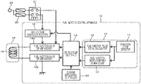
- FIG. 1 is a configuration diagram illustrating a basic configuration of a fuel injection control apparatus, which forms a foundation of the present invention.
- FIG. 2 is an explanatory diagram illustrating an example of a pulse string in multistage fuel injection control.
- FIG. 3 is an explanatory diagram used to explain a problem that may arise when the fuel injection control apparatus illustrated in FIG. 1 performs current integration control.
- FIG. 4 is an explanatory diagram illustrating current integration control for use in solving the problem illustrated in FIG. 3 .
- FIG. 5 is a configuration diagram illustrating a configuration of a fuel injection control apparatus according to a first embodiment of the present invention.
- FIG. 6 is a configuration diagram illustrating a configuration of a fuel injection pulse signal calculator illustrated in FIG. 5 .
- FIG. 7 is a characteristic diagram of a fuel injection amount and an injection pulse, which is used to explain a relationship between the fuel injection amount and the injection pulse.
- FIG. 8 is a configuration diagram illustrating a configuration of a target integrated current value calculator illustrated in FIG. 5 .
- FIG. 9 is a flowchart illustrating a control flow in a case where the current integration control according to the first embodiment of the present invention is performed by a microcomputer.
- FIG. 10 is a flowchart illustrating details of the current integration control illustrated in FIG. 9 .
- FIG. 11 is a configuration diagram illustrating a configuration of a fuel injection control apparatus according to a second embodiment of the present invention.
- FIG. 12 is an explanatory diagram used to explain functions of a ⁇ Tpeak calculator and a fuel injection drive waveform command unit illustrated in FIG. 11 .
- FIG. 13 is an explanatory diagram used to explain a method by which the ⁇ Tpeak calculator illustrated in FIG. 12 determines a ⁇ Tpeak.
- FIG. 14 is a flowchart illustrating a control flow in a case where the current integration control according to the second embodiment of the present invention is performed by a microcomputer.
- FIG. 1 illustrates a fuel injection control apparatus that performs half lift control and full lift control, which has a configuration that forms a foundation of the present invention.
- a fuel injection control apparatus 10 includes: an operation state detector 11 ; a fuel injection pulse signal calculator 12 ; a fuel injection drive waveform command unit 13 ; a drive circuit (custom IC) 14 ; a high-voltage generator (booster) 15 ; and fuel injection valve drivers 16 a and 16 b each of which includes a metal oxide semiconductor field-effect transistor (MOSFET), for example.
- the operation state detector 11 , the fuel injection pulse signal calculator 12 , and the fuel injection drive waveform command unit 13 are included in the microcomputer 17 . Of these, the fuel injection pulse signal calculator 12 and the fuel injection drive waveform command unit 13 are control functions based on a program.
- the operation state detector 11 detects various types of operation information regarding, for example, the number of revolutions of an internal combustion engine, an intake air amount, a temperature of cooling water, a fuel pressure, and a failure state of the internal combustion engine. Based on the operation information obtained from the operation state detector 11 , the fuel injection pulse signal calculator 12 calculates time widths of injection pulses which specify fuel injection times for electromagnetic fuel injection valves 18 , and the fuel injection drive waveform command unit 13 calculates command values of drive currents flowing through electromagnetic coils 19 and outputs the command values to the drive circuit 14 in order to maintain a valve opening operations of the electromagnetic fuel injection valves 18 and their valve open states.
- the fuel injection drive waveform command unit 13 determines a current characteristic (drive current profile), such as set current values in half lift control, and a current characteristic (drive current profile), such as set current values in full lift control, and then outputs these current characteristics to drive circuit 14 .
- a current characteristic such as set current values in half lift control
- drive current profile such as set current values in full lift control
- the high-voltage generator 15 which is implemented by a DC/DC converter, generates a high power supply voltage (referred to below as a high voltage) required to open the electromagnetic fuel injection valves 18 of an electromagnetic coil type, based on a voltage of a battery power source 22 supplied via a fuse 20 and an electromagnetic relay 21 . Furthermore, the high-voltage generator 15 boosts the voltage of the battery power source 22 so as to reach a desired target high voltage value, based on a command from the drive circuit 14 .
- a high voltage referred to below as a high voltage
- each electromagnetic fuel injection valve 18 Connected to an upstream end of the electromagnetic coil 19 provided in each electromagnetic fuel injection valve 18 is a fuel injection valve driver 16 a , whereas connected to a downstream end of the electromagnetic coil 19 is a fuel injection valve driver 16 b .
- the fuel injection valve driver 16 a is connected to both the high-voltage generator 15 and the battery power source 22 and selectively uses, as power sources of the electromagnetic fuel injection valves 18 , two voltage systems: a high voltage aiming to ensure a valve opening force of a valve body; and a battery voltage aiming to keep the valve open so that the opened valve does not close.
- the fuel injection valve driver 16 a selectively switches the power sources so that the battery voltage is applied after the high voltage is applied during the full lift control and so that only the high voltage is applied during the half lift control.
- the drive circuit 14 controls the fuel injection valve drivers 16 a and 16 b , each of which includes a MOSFET, thereby switching between the high voltage and the battery voltage which are to be applied to the electromagnetic fuel injection valve 18 or controls the drive currents supplied to the electromagnetic fuel injection valves 18 .
- the drive circuit 14 is connected to a current integration controller 23 , which will be described later, and receives a valve closing timing signal based on current integration when very small amounts of fuel are injected. Details will be described with reference to FIG. 3 .
- FIG. 2 illustrates a time-series application state of separated injection pulses, which are given to an electromagnetic fuel injection valve 18 in a case where the multistage injection control is performed.
- the multistage injection control illustrated in FIG. 2 will be described as a typical example, but it is not limited to this example because another method of ejecting very small amounts of fuel is conceivable.
- one combustion cycle is formed of “intake stroke”, “compression stroke”, “expansion stroke”, and “exhaust stroke”.
- Injection pulses are applied to each electromagnetic fuel injection valve 18 during a period from the “intake stroke” to the “compression stroke”.
- the full lift control in which time widths are set to be wide, as indicated by separated injection pulses PdF, is performed during the “intake stroke” and at the beginning of the subsequent “compression stroke”.
- the half lift control in which time widths are set to be narrow, as indicated by a separated injection pulse PdH, is performed in the middle of the “compression stroke”.
- a reason why the above separated injection is performed is that the most of target fuel amounts of fuel is injected during the “intake stroke” to form a lean, homogeneous air-fuel mixture, and then very small fuel amounts of fuel are injected during the “compression stroke” to form a partially rich mixture around a spark plug.
- the ignition can be reliably turned on by the spark plug, and the lean, homogeneous mixture can be burned by the combustion flame of the rich mixture.
- the combustion is caused by the lean air-fuel mixture as a whole, so that the fuel efficiency and exhaust performance are improved.
- the region in which the fuel is injected by the separated injection pulse PdH during the “compression stroke” corresponds to a very small fuel injection amount region of the half lift region.
- energy amounts of the drive currents flowing to the electromagnetic fuel injection valves 18 may differ from one another, thereby making lift amounts of the valve bodies different.
- variations in the amounts of fuel injected via the electromagnetic fuel injection valve 18 may occur.
- integrated current values of the drive currents supplied to the electromagnetic coils 19 of the electromagnetic fuel injection valves 18 are each regulated so as to become a predetermined target integrated current value. In this way, the machine difference between the electrical characteristics of the electromagnetic fuel injection valves 18 is compensated for, and variations in fuel injection amount are thereby reduced.
- the current integration control performed by the current integration controller 23 will be described with reference to FIG. 3 .
- FIG. 3 two electromagnetic fuel injection valves 18 are compared with each other, and the opening timings of the two electromagnetic fuel injection valves 18 are illustrated so as to coincide with each other in order to facilitate understanding.
- the electromagnetic fuel injection valve 18 operates in accordance with an operation sequence of the cylinders.
- this current integration operation is performed in synchronization with a valve opening timing TimgO of the separated injection pulse PdH.
- a valve opening timing TimgO of the separated injection pulse PdH When both the integrated current values ISa and ISb reach the predetermined target integrated current value IStrgt, second valve closing timings TimgRa and TimgRb are generated. Then, the drive current flowing through the electromagnetic coils 19 is interrupted, independently of a valve closing timing TimgC of the separated injection pulse PdH.
- the above control is possible by appropriately setting logic of the drive circuit 14 .
- the drive current also stops flowing through the electromagnetic coil 19 at the valve closing timing TimgC of the separated injection pulse PdH. Therefore, before both the integrated current values ISa and ISb reach the predetermined target current integration threshold IStrgt, the separated injection pulse PdH is shortened, as indicated by an arrow A, due to any reason such as the execution of the pulse width correction function of the separated injection pulse PdH, and the valve closing timing TimgC is thereby generated. Then, the drive current supplied to the electromagnetic coil 19 is forcibly interrupted.
- the electromagnetic fuel injection valves 18 a and 18 b operate in accordance with the operation sequence of the cylinders. Therefore, when the pulse width of the second separated injection pulse PdH of the electromagnetic fuel injection valve 18 b is corrected in a direction of shortening with respect to the first separated injection pulse PdH of the electromagnetic fuel injection valve 18 a , the above phenomenon prominently occurs. As a result, variations in fuel injection amounts newly occur, which may lead to deterioration of exhaust performance and fuel consumption efficiency.
- a configuration of the present invention includes a fixed injection pulse generator that generates a fixed injection pulse, as an injection pulse for use in driving an electromagnetic fuel injection valve.
- the fixed injection pulse has a valve opening timing at which a drive current is supplied to an electromagnetic coil in the electromagnetic fuel injection valve and a first valve closing timing at which the drive current supplied to the electromagnetic coil is interrupted.
- the configuration further includes a drive current interruption unit that, within a period in which the fixed injection pulse is generated, determines an electric energy amount of the drive current supplied to the electromagnetic coil in response to the valve opening timing of the fixed injection pulse. When this electric energy amount reaches a preset, predetermined target electric energy amount, the drive current interruption unit generates a second valve closing timing of the fixed injection pulse different from the first valve closing timing and interrupts the drive current supplied to the electromagnetic coil before the first valve closing timing.
- the second valve closing timing of the fixed injection pulse is generated only after the electric energy amount given to the electromagnetic coil reaches the preset, predetermined target electric energy amount and the first valve closing timing is generated. Therefore, the electromagnetic fuel injection valve reliably shifts to the valve closing operation at a time when the electric energy amount reliably reaches the target electric energy amount, thereby suppressing variations in fuel injection amounts to improve exhaust performance and fuel efficiency performance.
- FIG. 4 a basic concept of a first embodiment of the present invention will be described with reference to FIG. 4 .
- two electromagnetic fuel injection valves 18 are compared with each other, but similar to FIG. 3 , the opening timings of the two electromagnetic fuel injection valves 18 coincide with each other in order to facilitate understanding.
- a fixed separated injection pulse PdH(Fix) illustrated in FIG. 4(A) is an injection pulse with a constant time width T(Fix) which is not corrected by a pulse width correction function.
- the fixed separated injection pulse PdH (Fix) is set to at least a time width T(Fix) that exceeds times Tsa and Tsb in which integrated current values ISa and ISb of the drive currents flowing through the electromagnetic coils 19 in the electromagnetic fuel injection valves 18 reach a target integrated current value IStrgt.
- the time width T(Fix) of the fixed separated injection pulse PdH(Fix) is set to a time corresponds to a “minimum fuel injection amount” that can secure the linearity of “fuel injection amount vs injection pulse characteristic” (see FIG. 7 ) which is required for an internal combustion engine.
- the time width T(Fix) is not limited to the time corresponding to the “minimum fuel injection amount” and may also be set to another time width as required.
- the fixed separated injection pulse PdH (Fix) is given to the drive circuit 14 in accordance with a valve opening timing TimgO of the separated injection pulse PdH illustrated in FIG. 2 .
- a first valve closing timing TimgC is given to the drive circuit 14 .
- an integration operation of the drive current flowing through each electromagnetic coil 19 is initiated in synchronization with the valve opening timing TimgO.
- the second valve closing timings TimgRa and TinmgRb are generated.
- Each of the integration times Tsa and Tsb is a current drive zone in which the drive current flows through the electromagnetic coil 19 , and a subsequent zone that lasts until the first valve closing timing TimgC of the fixed separated injection pulse PdH(Fix) is a current interruption zone.
- the first valve closing timing TimgC of the fixed separated injection pulse PdH(Fix) is generated.
- both the second valve closing timings TimgRa and TinmgRb are reliably generated and supplied to the drive circuit 14 before the first valve closing timing TimgC of the fixed separated injection pulse PdH(Fix) is generated. It is thus possible to regulate each electromagnetic fuel injection valve 18 to the predetermined target integrated current value IStrgt, thereby reducing variations in fuel injection amounts caused by the machine difference between the electrical characteristics of the electromagnetic fuel injection valves 18 .
- the configuration of the present embodiment includes a fixed injection pulse generator that generates a fixed injection pulse PdH(Fix), as an injection pulse for use in driving an electromagnetic fuel injection valve 18 .
- the fixed injection pulse has a valve opening timing TimgO at which a drive current is supplied to an electromagnetic coil 19 in the electromagnetic fuel injection valve 18 and a first valve closing timing TimgC at which the drive current supplied to the electromagnetic coil 19 is interrupted.
- the configuration further includes a drive current interruption unit that, within a period T(Fix) in which the fixed injection pulse PdH(Fix) is generated, determines an electric energy amount IS of the drive current supplied to the electromagnetic coil 19 in response to the valve opening timing TimgO of the fixed injection pulse PdH(Fix).
- the drive current interruption unit When the determined electric energy amount reaches a preset, predetermined target electric energy amount IStrgt, the drive current interruption unit generates a second valve closing timing TimgR of the fixed injection pulse PdH(Fix) different from the first valve closing timing TimgC and interrupts the drive current supplied to the electromagnetic coil 19 before the first valve closing timing TimgC.
- the target integrated current value IStrgt is determined in advance so as to correspond to the amount of fuel injected by the separated injection pulse PdH.
- the target integrated current value IStrgt can be determined by an adaptive method (matching) or simulation.
- an operation state detector 11 detects an operation state amount representative of an operation state of an internal combustion engine and then supplies this operation state amount to a fuel injection pulse signal calculator 30 that is newly provided.
- This new fuel injection pulse signal calculator 30 has a function of calculating the amount of fuel injected via each electromagnetic fuel injection valve 18 , a function of converting the amount of fuel into separated injection pulses PdF for the full lift control and a separated injection pulse PdH for the half lift control as illustrated in FIG. 2 , and a function of selectively replacing a separated injection pulse PdH for the half lift control with the fixed separated injection pulse PdH(Fix).
- a pulse converter in a separated injection pulse calculator 30 A generates a pulse string containing the separated pulses PdF for full lift control of each electromagnetic fuel injection valve 18 and the subsequent separated pulse PdH for the half lift control.
- the pulse converter replaces this last separated pulse PdH for the half lift control with the fixed injection pulse PdH(Fix).
- the fuel injection pulse signal calculator 30 supplies a drive circuit 32 with the pulse string containing the separated injection pulses PdF for the full lift control and either the separated injection pulse PdH for the half lift control or a fixed separated injection pulse PdH(Fix) for the half lift control, which are obtained by calculation.
- the fuel injection pulse signal calculator 30 simultaneously supplies a current integration permission command and a request fuel injection amount related to the separated injection pulse PdH to a target integrated current value calculator 31 A and an integrated current value calculator 31 B, which constitute a current integration controller 31 that will be described below.
- FIG. 6 illustrates a schematic configuration of the above fuel injection pulse signal calculator 30 .
- the fuel injection pulse signal calculator 30 includes the separated injection pulse calculator 30 A, a fixed separated injection pulse calculator 30 B, and a pulse width/current integration determiner 30 C. These separated injection pulse calculator 30 A, fixed separated injection pulse calculator 30 B, and pulse width/current integration determiner 30 C are also implemented as control functions based on a program in the microcomputer 17 .
- the separated injection pulse calculator 30 A determines a target fuel injection amount required for one combustion cycle, based on the operation information on the internal combustion engine from the operation state detector 11 . Then, based on the target fuel injection amount, the separated injection pulse calculator 30 A calculates injection pulses for use in separately injecting the fuel a plurality of time.
- the separated injection pulse calculator 30 A calculates the separated injection pulse string, as illustrated in FIG. 2 .
- the pulse string contains the separated injection pulses PdF for the full lift control and the separated injection pulse PdH for the half lift control is generated.
- the fixed separated injection pulse calculator 30 B when the current integration control is performed in the above manner, generates the fixed separated injection pulse PdH(Fix) that has a function of preventing the drive current flowing through each electromagnetic coil 19 from being interrupted before the second valve closing timing TimgR due to a varying first valve closing timing TimgC of the separated injection pulse PdH.
- the fixed separated injection pulse PdH(Fix) is stored in a storage device such as a table and is read when the pulse width/current integration determiner 30 C, which will be described later, performs a comparison operation of the separated injection pulse PdH.
- the fixed separated injection pulse PdH(Fix) functions as a “comparison pulse”. As illustrated in FIG. 7 , the fixed separated injection pulse PdH(Fix) is set to a time width corresponding to the “minimum fuel injection amount” that ensures the linearity of the flow amount characteristic of the fuel injection amount (Fq) and the injection pule width (Ti). Thus, if the fixed separated injection pulse PdH(Fix) is narrower than this time width, the characteristic enters into a region where a very small amount of fuel is injected, varying the fuel injection amounts caused by the machine difference between the electromagnetic fuel injection valves 18 . In this state, it is necessary to perform the current integration control to suppress the variations in the fuel injection amounts caused by the machine difference between the electromagnetic fuel injection valves 18 .
- the pulse width/current integration determiner 30 C is provided with a “pulse comparator”, which receives the separated injection pulses PdF and PdH from the separated injection pulse calculator 30 A and the fixed separated injection pulse PdH(Fix) from the fixed separated injection pulse calculator 30 B. Then, the pulse comparator compares the individual pulse widths of these injection pulses, thereby determining whether to perform the current integration control.
- the pulse width of the comparison pulse to be compared by the pulse comparator in the pulse width/current integration determiner 30 C is set to a time width corresponding to the “minimum fuel injection amount” that ensures the linearity of the flow rate characteristic of the fuel injection amount and the injection pulse width.
- the fixed separated injection pulse PdH(Fix) and the separated injection pulses PdF and PdH may be compared in order.
- the last separated injection pulse PdH and the fixed separated injection pulse PdH(Fix) may be compared if the separated injection pulse PdH for the half lift control is known. This is because in the pulse string illustrated in FIG. 2 , the last injection pulse corresponds to the separated injection pulse PdH.
- the separated injection pulse PdH which is known in advance as a separated injection pulse for the half lift control, is preferably compared with the fixed separated injection pulse PdH(Fix).
- the pulse width/current integration determiner 30 C compares at least the pulse widths of the separated injection pulse PdH for the half lift control from the separated injection pulse calculator 30 A and the fixed separated injection pulse PdH(Fix) from the fixed separated injection pulse calculator 30 B. Then, when determining that the pulse width of the separated injection pulse PdH for the half lift control is wider than that of the fixed separated injection pulse PdH(Fix), the pulse width/current integration determiner 30 C outputs the pulse string determined by the separated injection pulse calculator 30 A to the drive circuit 32 without performing any processing. It is obvious that the pulse width/current integration determiner 30 C does not perform the current integration control.
- the “pulse converter” provided in the pulse width/current integration determiner 30 C replaces the separated injection pulse PdH determined by the separated injection pulse calculator 30 A with the fixed separated injection pulse PdH(Fix). Then, the pulse width/current integration determiner 30 C outputs the resultant pulse string to the drive circuit 32 .
- the pulse width of the comparison pulse is set to the same as the pulse width of the fixed injection pulse PdH(Fix).
- the separated injection pulse PdH has been replaced by the fixed separated injection pulse PdH(Fix).
- the valve opening timing TimgO of the fixed separated injection pulse PdH(Fix) is set to so as to coincide with the valve opening timing TimgO of the separated injection pulse PdH for the half lift control.
- the configuration of the present embodiment includes the separated injection pulse calculator 30 A that forms a plurality of separated injection pulses by dividing a target fuel injection amount required for one combustion cycle by a predetermined separation number.
- the configuration further includes a pulse comparator that compares the pulse widths of the separated injection pulse and one or more preset, predetermined comparison pulses.
- the configuration further includes a pulse converter that, when the pulse comparator determines that the separated injection pulse is narrower, replaces the separated injection pulse determined to be narrower with the fixed injection pulse from the fixed injection pulse generator.
- the pulse width/current integration determiner 30 C outputs the current integration permission command and the request fuel injection amount corresponding to the separated injection pulse PdH for the half lift control.
- the request fuel injection amount is given to the target integrated current value calculator 31 A
- the current integration permission command is given to both the target integrated current value calculator 31 A and the current integration calculator 31 B.
- the current integration controller 31 is activated.
- the current integration controller 31 functions as a “drive current interruption unit”.
- the current integration controller 31 includes the target integrated current value calculator 31 A, the integrated current value calculator 31 B, and an integrated current value comparator 31 C.
- the target integrated current value calculator 31 A is implemented as a control function based on the program of the microcomputer 17 .
- both of the integrated current value calculator 31 B and the integrated current value comparator 31 C are implemented in hardware, they can be replaced with the control function of the microcomputer as needed.
- the target integrated current value calculator 31 A is activated in response to the current integration permission command from the fuel injection pulse signal calculator 30 . Then, the target integrated current value calculator 31 A calculates the request fuel injection amount depending on the separated injection pulse PdH that has been determined by the fuel injection pulse signal calculator 30 . The target integrated current value IStrgt is thereby determined depending on the request fuel injection amount.
- FIG. 8 illustrates a configuration of the target integrated current value calculator 31 A.
- the target integrated current value calculator 31 A has a map in which a horizontal axis represents the request fuel injection amount and a vertical axis represents the target integrated current value.
- the target integrated current value calculator 31 A receives the current integration permission command and the request fuel injection amount from the fuel injection pulse calculator 30 .
- the target integrated current value calculator 31 A searches the map for the target integrated current value IStrgt corresponding to the request fuel injection amount and then outputs the target integrated current value IStrgt to the integrated current value comparator 31 C.
- the target integrated current value IStrgt is determined in advance by using a standard (reference) electromagnetic fuel injection valve and by a suitable method (matching) or simulation, and in relation to the request fuel injection amount corresponding to the separated injection pulse PdH.
- the target integrated current value IStrgt is set to a target integrated current value IStrgt that is smaller than the target integrated current value depending on the fuel injection amount corresponding to the fixed separated injection pulse PdH(Fix) and stored in the map. Since the calculation is performed by the map search, the calculation time can be shortened as compared with the arithmetic calculation, which contributes to the control with good responsiveness.
- the target integrated value IStrgt is determined from the map that stores the target integrated current value corresponding to the request fuel injection amount determined in advance in the standard electromagnetic fuel injection valve.
- the integrated current value calculator 31 B is activated in response to the current integration permission command from the fuel injection pulse signal calculator 30 . More specifically, the integrated current value calculator 31 B is activated in synchronization with the valve opening timing TimgO of the fixed separated injection pulse PdH(Fix). Then, the integrated current value calculator 31 B detects the drive current flowing through the electromagnetic coil 19 in each electromagnetic fuel injection valve 18 and performs the current integration operation. The valve opening timing TimgO of the fixed separated injection pulse PdH(Fix) coincides with the valve opening timing TimgO of the separated injection pulse PdH.
- the drive circuit 32 validates a valve closing timing that is one of the first valve closing signal based on the first valve closing timing TimgC and the second valve closing signal based on the second valve closing timing TimgR which has been supplied earlier to the drive circuit 32 .
- the drive current interruption unit (current integration controller 31 ) determines the integrated current value of the drive current supplied to each electromagnetic coil 19 in synchronization with the valve opening signal TimgO. Then, when the determined integrated current value reaches the preset, predetermined target integrated current value IStrgt, the drive current interruption unit supplies the drive circuit with the second valve closing signal based on the second valve closing timing TimgR.
- the drive circuit 32 controls the gates of the MOSFETs forming the fuel injection valve drivers 16 a and 16 b in response to injection pulses transmitted from the fuel injection pulse signal calculator 30 .
- the drive circuit 32 When the full lift control is performed, the drive circuit 32 simultaneously turns on the fuel injection valve drivers 16 a and 16 b in synchronization with the valve opening timing TimgO of the separated injection pulse PdF and, in turn, simultaneously turns off the fuel injection valve drivers 16 a and 16 b in synchronization with the first valve closing timing TimgC.
- the drive circuit 32 When the half lift control is performed and the pulse width of the separated injection pulse PdH is wider than the pulse width of the fixed separated injection pulse PdH(Fix), the drive circuit 32 simultaneously turns on the fuel injection valve drivers 16 a and 16 b in synchronization with the valve opening timing TimgO of the separated injection pulse PdH that has not been replaced by the fixed separated injection pulse PdH(Fix) and, in turn, simultaneously turns off the fuel injection valve drivers 16 a and 16 b in synchronization with the first valve closing timing TimgC.
- the pulse width of the separated split injection pulse PdH is wider than the pulse width of the fixed separated injection pulse PdH(Fix) as described above, the linearity is ensured as illustrated in FIG. 7 and thus variations in the fuel injection amounts can be a less serious problem.
- the linearity is not ensured as illustrated in FIG. 7 , and thus variations in the fuel injection amounts can turn out to be a problem, in which case the current integration control is performed.
- the pulse width of the separated injection pulse PdH is narrower than the pulse width of the fixed separated injection pulse PdH(Fix)
- the separated injection pulse PdH is first replaced with the fixed separated injection pulse PdH (Fix).
- the drive circuit 32 simultaneously turns on the fuel injection valve drivers 16 a and 16 b in synchronization with the valve opening timing TimgO of the fixed separated injection pulse PdH(Fix) and, in turn, simultaneously turns off the fuel injection valve drivers 16 a and 16 b in synchronization with the second valve closing timing TimgR from the current integration controller 31 .
- the drive circuit 32 receives the first valve closing timing TimgC of the fixed separated injection pulse PdH(Fix), it invalidates the first valve closing timing TimgC.
- the fixed injection pulse generator 30 B supplies the drive circuit 32 with the valve opening signal based on the valve opening timing TimgO and the first valve closing signal based on the first valve closing timing TimgC.
- the drive circuit 32 supplies the drive current to each electromagnetic coil 19 .
- the drive current interruption unit (current integration controller) 31 determines the electric energy amount of the drive current supplied to each electromagnetic coil 19 . When the determined electric energy amount reaches a preset, predetermined target electric energy amount, the drive current interruption unit 31 supplies the drive circuit 32 with the second valve closing signal based on the second valve closing timing TimgR, thereby interrupting the drive current supplied to each electromagnetic coil.
- the drive current interruption unit (current integration controller) 31 includes the integrated current value calculator 31 B, the target integrated current value calculator 31 A, and the current integration comparator.
- the integrated current value calculator 31 B determines the integrated current value of the drive current supplied to each electromagnetic coil 19 in synchronization with the valve opening signal.
- the target integrated current value calculator 31 A determines a target integrated current value corresponding to the request fuel injection amount injected from the electromagnetic fuel injection valve 18 .
- the current integration comparator generates the second valve closing signal to supply the second valve closing signal to the drive circuit at the time when the integrated current value reaches the target integrated current value.
- the current drive zone is reserved between the valve opening timing TimgO at which the drive current is supplied to each electromagnetic coil 19 and the second valve closing timing TimgR at which the integrated current value reaches the target integrated current value IStrgt and the drive current is interrupted.
- the second valve closing timing TimgR a zone in which counter electromotive force rapidly reduces the drive current is reserved and is contained in a current interruption zone.
- the pulse width of the fixed separated injection pulse PdH(Fix) is set to the sum of the current drive zone and the current interruption zone containing the zone in which the counter electromotive force rapidly reduces the drive current. In short, the pulse width of the fixed separated injection pulse PdH(Fix) is wider than the time span in which the drive current is supplied to each electromagnetic coil 19 , interrupted, and converges to zero.
- the pulse width of the fixed injection pulse PdH(Fix) is set to be wider than the time span in which the drive circuit 32 supplies the drive current to each electromagnetic coil 19 and interrupts the drive current according to the second valve closing signal TimeR, which then converges to zero.
- the pulse width of the fixed separated injection pulse PdH(Fix) is set to be the same as the pulse width of the comparison pulse for use in determining whether the current integration controller 31 performs the current integration control. Therefore, after the current integration control is performed, the first valve closing timing TimgC of the fixed separated injection pulse PdH(Fix) is generated. As a result, it is possible to reliably obtain the second valve closing timing TimgR from the current integration controller 31 , thereby successfully suppressing variations in the fuel injection amounts caused by the machine difference between the electrical components of the electromagnetic fuel injection valves.
- the pulse width of fixed separated injection pulse PdH(Fix) may be set to a plurality of pulse widths other than the pulse width described above.
- FIG. 9 is a flowchart of a mode in which the fuel is injected under pulse width control in a region where linearity can be ensured illustrated in FIG. 7 and a mode in which the fuel is injected under the current integration control in a region where linearity cannot be secured.
- the preceding two separated injection pulses PdF determine a fuel injection amount under the pulse width control
- the fixed separated injection pulse PdH(Fix) following the separated injection pulses PdF determines a fuel injection amount under the current integration control.
- Step S 10 various types of operation information regarding the number of revolutions of the internal combustion engine, the amount of intake air, a temperature of the cooling water, a fuel pressure, and a failure state of the internal combustion engine, for example, are detected. This operation information is used to determine a target fuel injection amount or the separated number of injection pulses, for example. After the operation information on the internal combustion engine is detected, the process proceeds to step S 1 .
- Step S 11 from the detected operation information, the target fuel injection amount or the separated number of injection pulses are determined.
- the target fuel injection amount is obtained by multiplying a basic fuel injection amount by various correction coefficients, the basic fuel injection amount being obtained by dividing the air amount by the number of the revolutions.
- the separated number is determined in accordance with variables such as a load, an air amount, and the number of revolutions, and a valve opening timing at which the fuel injection starts in response to the separated injection pulse is also determined together. In this way, when the target fuel injection amount, the separated number, the valve opening timing, for example, are determined in step S 1 , the process proceeds to step S 12 .
- Step S 12 based on the target fuel injection amount, the separated number, and the valve opening timing, for example, pulse widths of the separated injection pulses are determined.
- the pulse widths are determined in a manner similar to the way that the two separated injection pulses PdF and one separated injection pulse PdH following the separated injection pulses PdF in FIG. 2 are determined.
- This control amount is determined before the fuel is injected in response to the first separated injection pulse. Then, in the “intake stroke” and at the beginning of the subsequent “compression stroke”, the fuel is injected twice in response to the separated injection pulses PdF. In the middle of the “compression stroke”, the fuel is injected once in response to the separated injection pulse PdH.
- the separated injection pulse calculator 30 A calculates the pulse string before the fuel is injected in response to the first separated injection pulse PdF.
- a reason why the above separated injection is performed is that the most of target fuel amounts of fuel is injected during the “intake stroke” to form a lean, homogeneous air-fuel mixture, and then very small fuel amounts of fuel are injected during the “compression stroke” to form a partially rich mixture around a spark plug.
- This injection pattern is a typical example; however, it is obvious that the injection pattern may include a plurality of separated injection pulses with the same pulse width. After the pulse widths of the separated injection pulses are determined, the process proceeds to step S 13 .
- Step S 13 each of the pulse widths of the separated injection pulses PdF and PdH is compared with the fixed separated injection pulse PdH(Fix).
- the preceding two separated injection pulses PdF are used for the full lift and thus their pulse width is reliably wider than that of the fixed separated injection pulse PdH(Fix).
- the process proceeds to step S 14 in which the control is performed based on the pulse width.
- the separated injection pulse PdH following the preceding separated injection pulse PdF is used for the operation of the half lift, in which cases its pulse width may be longer or shorter than the fixed separated injection pulse PdH(Fix).
- step S 14 control is performed based on the pulse width.
- step S 16 control is performed based on the current integration.
- each of the separated injection pulses PdF and PdH is compared with the pulse width of the fixed separated injection pulse PdH(Fix).
- the separated injection pulses PdF do not necessarily to be compared with the fixed division injection pulse PdH(Fix), in other words, only the separated injection pulse PdH may be compared with the fixed division injection pulse PdH(Fix). This is because it is already known that the separated injection pulses PdF are used for the full lift control.
- Step S 14 various electronic control components are controlled in order to perform the control based on the pulse width.
- the valve opening timing TimgO and the valve opening time (pulse width) are set for an output register in an input/output circuit (IO/LSI).
- IO/LSI input/output circuit
- step S 15 Those setting steps may be individually performed in relation to the separated injection pulses PdF and PdH.
- Step S 15 based on the valve opening timing TimgO and the valve opening time (pulse width) set for the output register in the input/output circuit (IO/LSI), a valve opening signal and a valve closing signal are output to the drive circuit 32 in response to the separated injection pulses PdF and PdH.
- Step S 11 to S 15 in which the control is performed based on a normal pulse width, will not be described anymore.
- Step S 16 The process returns to step S 13 , in which the pulse width of each of the separated injection pulses PdF and PdH is compared with that of the fixed separated injection pulse PdH(Fix). Then, when, of the separated injection pulse group, only the separated injection pulse PdH is narrower than the fixed injection pulse PdH(Fix), the linearity of the electromagnetic fuel injection valve is not ensured. Therefore, step S 16 in which the control is performed based on the current integration is performed.
- step S 16 instead of the separated injection pulse PdH, the fixed separated injection pulse PdH(Fix) whose valve opening timing coincides with the valve opening timing TimgO of the separated injection pulse PdH is set for the output register in the input/output circuit (IO/LSI).
- the fixed separated injection pulse PdH(Fix) has a function of preventing the drive current flowing through each electromagnetic coil 19 from being interrupted by the current integration control before the second valve closing timing TimgR, as described above.
- the fixed separated injection pulse PdH(Fix) is set to a time width corresponding to the “minimum fuel injection amount” that ensures the linearity of the flow amount characteristic of the fuel injection amount (Fq) vs the injection pule width (Ti).
- the valve opening timing TimgO and the valve opening time (pulse width) of the fixed separated injection pulse PdH(Fix) are set for the output register in the input/output circuit (IO/LSI)
- the process proceeds to step S 17 .
- the number of separated fuel injections is preset (e.g., three times), and the pulse width of the last separated injection pulse PdH for one combustion cycle is at least replaced with the fixed separated injection pulse PdH(Fix).
- the pulse width of the last separated injection pulse PdH for one combustion cycle is at least replaced with the fixed separated injection pulse PdH(Fix).
- Step S 17 based on the valve opening timing and the valve opening time (pulse width) set for the output register in the input/output circuit (IO/LSI) and in relation to the fixed separated injection pulse PdH(Fix), the valve opening signal and the valve closing signal are output to the drive circuit 32 in synchronization with the valve opening timing TimgO and the first valve closing timing TimgC as illustrated in FIG. 4 .
- the valve opening signal (valve opening timing TimgO) is output in step S 17
- the process proceeds to step S 18 .
- Step S 18 the control is performed based on the current integration. This control is performed in accordance with the control flow illustrated in FIG. 10 , and detailed control will be described with reference to FIG. 10 . Then, when the current integration control is performed and then the valve closing timing is output, the process proceeds to step S 19 .
- Step S 19 the valve closing signal is output to the drive circuit 32 in synchronization with the second valve closing timing TimgR output under the current integration control.
- the drive circuit 32 In synchronization with the second valve closing timing TimgR, the drive circuit 32 simultaneously turns off the fuel injection valve drivers 16 a and 16 b .
- the drive circuit 32 receives the valve closing signal in synchronization with the first valve closing timing TimgC of the fixed separated injection pulse PdH(Fix) as a result of the execution of step S 17 .
- the drive circuit 32 invalidates this valve closing signal based on the first valve closing timing TimgC because it already receives the valve closing signal based on the second valve closing timing TimgR. This can reliably perform the fuel injection control under the current integration control.
- the drive circuit 32 validates the valve closing timing that is one of the first valve closing signal based on the first valve closing timing TimgC and the second valve closing signal based on the second valve closing timing TimgR which has been supplied earlier to the drive circuit 32 .
- the last separated injection pulse PdH is used for the half lift control, and this last separated injection pulse PdH is replaced with the fixed separated injection pulse PdH(Fix).
- a separated injection pulse when the separated injection amount is less than or equal to a predetermined value, a separated injection pulse when the number of separated injections is greater than or equal to a predetermined value, or a separated injection pulse when the injection start timing or the injection completion timing is later than the predetermined timing is used for the half lift control.
- the separated injection pulse can be replaced with the fixed separated injection pulse PdH(Fix) as in the control step described above. It is obvious the separated injection pulse used for the half lift control is compared with the fixed separated injection pulse PdH(Fix).
- the separated injection pulse calculator 30 A considers that the separated injection pulse when the number of separated injections is equal to or greater than the predetermined number or the separated injection pulse when the valve opening timing or the injection completion timing of the electromagnetic fuel injection valve is later than a predetermined timing is used for the half lift control.
- the pulse comparator and the pulse converter determine that the divided pulse is narrower than the fixed injection pulse, the separated pulse can be replaced with the fixed injection pulse.
- step S 18 details of the current integration control in step S 18 will be described with reference to FIG. 10 .
- step S 20 the target integrated current value IStrgt corresponding to the request fuel injection amount is found from the map in which the horizontal axis represents the request fuel injection amount and the vertical axis represents the target integrated current value.
- the request fuel injection amount refers to a request fuel injection amount corresponding to the separated injection pulse PdH, and this request fuel injection amount is a very small fuel injection amount to be influenced by the machine difference between the electromagnetic fuel injection valves. Therefore, it is necessary to suppress the machine difference influence by using the current integration control.
- the process proceeds to step S 21 .
- Step S 21 the drive current flowing through the electromagnetic coil 19 in each electromagnetic fuel injection valve is subjected to time integration in synchronization with the valve opening timing TimgO of the fixed separated injection pulse PdH(Fix).
- This integrated current value represents the amount of electric energy supplied to each electromagnetic coil 19 .
- the process proceeds to step S 22 .
- Step S 22 the target integrated current value determined in step S 21 is compared with the momently increased integrated current value determined in step S 22 .
- the control steps in steps S 21 and S 22 are performed again.
- the integrated current value has reached the target integrated current value, it is considered that the target electric energy amount has been supplied to each electromagnetic coil 19 . Then, the process proceeds to step S 23 .
- Step S 23 since the target electric energy amount is considered to be supplied to each electromagnetic coil 19 , the second valve closing timing TimgR is output. It should be noted that, as described above, the target electric energy amount has a substantially equivalent relationship with the request fuel injection amount corresponding to the separated injection pulse PdH.
- the second valve closing timing TimgR is output to the drive circuit 32 as a valve closing signal in step S 19 of FIG. 9 to simultaneously turns off the fuel injection valve drivers 16 a and 16 b.
- a configuration of the present embodiment includes a separated injection pulse calculator 30 A that forms a plurality of separated injection pulses PdF and PdH by dividing a target fuel injection amount required for one combustion cycle by a predetermined separated number.
- the configuration further includes a pulse converter that compares a pulse width of a separated injection pulse with that of a preset, predetermined fixed separated injection pulse PdH(Fix). When the separated injection pulse is narrower, the pulse converter replaces the narrower separated injection pulse with fixed separated injection pulse PdH(Fix).
- the configuration further includes a current integration controller 31 that, within a period T(Fix) in which the fixed separated injection pulse PdH(Fix) is generated, determines an integrated current value IS of a drive current supplied to an electromagnetic coil 19 in synchronization with a valve opening timing TimgO of the fixed separated injection pulse PdH(Fix).
- the current integration controller 31 When the determined integrated current value IS reaches a preset, predetermined target integrated current value IStrgt, the current integration controller 31 generates a valve closing timing earlier than a valve closing timing TimgC of the fixed separated injection pulse PdH(Fix).
- the configuration further includes a drive circuit 32 that supplies the drive current to the electromagnetic coil in synchronization with a valve opening timing of a fixed separated injection pulse and interrupts the drive current supplied to the electromagnetic coil in synchronization with a valve closing timing that is an earlier one of a valve closing timing TimeC based on the fixed separated injection pulse PdH(Fix) and a valve closing timing TimgR from the current integration controller 31 .
- an integrated value of a drive current supplied to the electromagnetic coil 19 in the electromagnetic fuel injection valve is determined in synchronization with a valve opening timing of a fixed injection pulse with a predetermined constant time width.
- a valve closing timing is generated to interrupt the drive current supplied to the electromagnetic coil 19 .
- a pulse closing timing of the fixed injection pulse is generated only after the drive current is interrupted.
- a valve closing timing of a fixed injection pulse is generated only after an integrated current value given to the electromagnetic coil 19 reaches a preset, predetermined target integrated current value.
- the electromagnetic fuel injection valve always shifts to a valve closing operation. This can suppress variations in fuel injection amounts, thereby successfully improving exhaust performance and fuel efficiency performance.
- the foregoing first embodiment employs a system in which a target integrated current value is compared with an actual integrated current value. Then, when both the integration values coincide with each other, a valve closing signal is generated.
- the second embodiment proposes a system in which an integrated current value comparator is not provided.
- a fuel injection control apparatus illustrated in FIG. 11 is basically based on the configuration of the first embodiment, the same components as those illustrated in FIG. 5 will not be described.
- a ⁇ Tpeak calculator 31 D is newly provided instead of the integrated current value comparator 31 C.
- the ⁇ Tpeak calculator 31 D has a function of determining a time difference between a target arrival time and an actual arrival time.
- the target arrival time refers to a time until an integrated current value reaches a target integrated current value IStrgt when a standard (reference) electromagnetic fuel injection valve is used.
- the actual arrival time refers to a time until an integrated current value for an actual electromagnetic fuel injection valve 18 reaches the target integrated current value IStrgt. This time difference represents a machine difference between electromagnetic fuel injection valves.
- the time difference determined by the ⁇ Tpeak calculator 31 D is transmitted to a fuel injection drive waveform command unit 33 , and then a valve closing timing for current integration control is determined.
- the ⁇ Tpeak calculator 31 D and the fuel injection drive waveform command unit 33 function as a “drive current interruption unit”.
- This valve closing timing is determined as follows. First, a “correction time”, which is equivalent to the time difference, is subtracted from or added to the target current supply time until the integrated current value reaches the target integrated current value IStrgt when the standard (reference) electromagnetic fuel injection valve is used. An actual current supply time is thereby calculated. Then, a drive current is fed from a basic time point, or a valve opening timing TimgO of a fixed separated injection pulse PdH(Fix). A time at which the calculated actual current supply time has passed is regarded as a second valve closing timing TimgR. In this way, the second valve closing timing TimgR can be obtained without the use of the current integration comparator.
- FIGS. 12 and 13 each illustrate a method in which the ⁇ Tpeak calculator 31 D determines the time difference.
- the ⁇ Tpeak calculator 31 D receives the target integrated current value IStrgt from a target integrated current value calculator 31 A and also receives an integrated current value IS from the integrated current value calculator 31 B; the integrated current value IS refers to a value determined by momently integrating the drive current supplied to an electromagnetic coil 19 in each electromagnetic fuel injection valve 18 .
- the target integrated current value IStrgt and the integrated current value IS are received in order to determine a target arrival time Trexm and an actual arrival time Tract.
- the target integrated current value IStrgt refers to a target time until the integrated value reaches the target integrated current value IStrgt when the drive current passes through the electromagnetic coil 19 in the standard (reference) electromagnetic fuel injection valve.
- the integrated current value IS refers to an actual time until the integrated value for the electromagnetic fuel injection valve 18 reaches the target integrated current value IStrgt.
- FIG. 13 illustrates a method in which the ⁇ Tpeak calculator 31 D determines a time difference ⁇ Tpeak between two electromagnetic fuel injection valves 18 a and 18 b .
- a time at which an integration value ISexm reaches the target integrated current value IStrgt is set to the target arrival time Trexm.
- integrated values ISract-a (electromagnetic fuel injection valve 18 a ) and ISract-b (electromagnetic fuel injection Valve 18 b ) of the drive currents flowing through the electromagnetic coils 19 in the electromagnetic fuel injection valves 18 a and 18 b are determined.
- the actual arrival time Tract-a of the electromagnetic fuel injection valve 18 a is earlier than the target arrival time Trexm by the time difference ⁇ Tpeak-a, whereas the actual arrival time Tract-b of the electromagnetic fuel injection valve 18 b is later than the target arrival time Trexm by the time difference ⁇ Tpeak-b.
- the time difference ⁇ Tpeak represents the machine difference between the electromagnetic fuel injection valves. Since the machine difference differs from electromagnetic fuel injection valve 18 to electromagnetic fuel injection valve 18 , the time difference ⁇ Tpeak needs to be calculated and determined for each electromagnetic fuel injection valve 18 .
- the time difference ⁇ Tpeak is supplied to the fuel injection drive waveform command unit 33 , and the second valve closing timing TimgR is determined, but in this case, the actual current supply time is determined.
- the target integrated current value IStrgt is supplied to the fuel injection drive waveform command unit 33 , and the target current supply time corresponding to this target integrated current value IStrgt is set.
- the target current supply time which corresponds to the target integrated current value IStrgt, is also determined in advance by an adaptive method (matching) or simulation.
- the actual current supply time is determined from “target current supply time ⁇ Tpeak-a”.
- the actual current supply time is determined from “target current supply time+ ⁇ Tpeak-b”. In this way, the second valve closing timing TimgR for the electromagnetic fuel injection valve 18 can be determined.
- a pulse string is output from a fuel injection pulse signal calculator 30 to a drive circuit 32 as in example 1.
- a pulse width of a separated injection pulse PdH is narrower than that of the fixed separated injection pulse PdH(Fix)
- the current integration control is performed.
- the fixed separated injection pulse PdH(Fix) for half lift control will be described.
- the fuel injection drive waveform command unit 33 controls the drive current flowing through the electromagnetic coil 19 based on a drive current profile, in synchronization with the fixed separated injection pulse PdH(Fix).
- the current integration control is performed as in example 1, and the time difference ⁇ Tpeak is obtained by the ⁇ Tpeak calculator 31 D as described above.
- the time difference ⁇ Tpeak is supplied to the fuel injection drive waveform command unit 33 , and then the actual current supply time is determined by subtracting or adding the time difference ⁇ Tpeak from/to the target current supply time, as described above.
- the drive current is supplied over the determined actual current supply time from the starting point, which is the valve opening timing TimgO of the fixed separated injection pulse PdH(Fix). Then, a time d at which the actual current supply time has passed is regarded as the second valve closing timing TimgR, and the drive current is interrupted. It is obvious that, after the second valve closing timing TimgR, the valve closing signal of the first valve closing timing TimgC of the fixed separated injection pulse PdH(Fix) is supplied to the drive circuit 32 , as in example 1.
- the drive current interruption unit (fuel injection drive waveform command unit) 33 determines an integrated current value of a drive current supplied to the electromagnetic coil 19 in synchronization with the valve opening signal TimgO. Based on this integrated current value, the drive current interruption unit 33 determines a current supply time in which the drive current is supplied to the electromagnetic coil 19 . When a conduction time of the drive current supplied to the electromagnetic coil 19 in synchronization with the valve opening signal TimgO reaches the current supply time, the drive current interruption unit 33 generates the second valve closing timing TimgR and supplies this second valve closing signal to a drive circuit 32 .
- the drive current interruption unit determines the current supply time of the drive current supplied to the electromagnetic coil 19 from the target current supply time Trexm and the correction time ⁇ Tpeak.
- the target current supply time Trexm is determined from the target integrated current value corresponding to the request fuel injection amount injected from the electromagnetic fuel injection valve 18 ; and the correction time ⁇ Tpeak is determined from the integrated current value IS of the drive current supplied to the electromagnetic coil 19 in synchronization with the valve opening signal TimgO.
- the drive current interruption unit When the conduction time of the drive current supplied to the electromagnetic coil 19 in synchronization with the valve opening signal TimgO reaches the current supply time, the drive current interruption unit generates the second valve closing timing TimgR and supplies the second valve closing signal is supplied to the drive circuit 32 .
- FIG. 14 a description will be given of a control flow in a case where the operations illustrated in FIGS. 12 and 13 performed by a microcomputer. Since details have been described above, control steps will be described briefly below.
- Step S 30 the target integrated current value IStrgt corresponding to the request fuel injection amount is found from the map in which the horizontal axis represents the request fuel injection amount and the vertical axis represents the target integrated current value.
- the request fuel injection amount refers to a request fuel injection amount corresponding to the separated injection pulse PdH, and this request fuel injection amount is a small amount fuel injection amount to be influenced by the machine difference between the electromagnetic fuel injection valves 18 .
- the process proceeds to step S 31 .
- Step S 31 the target arrival time Trexm is determined, until the integrated value reaches the target integrated current value IStrgt when the drive current flows through the electromagnetic coil 19 in the standard (reference) electromagnetic fuel injection valve 18 . This is determined in advance by a matching method (matching) or simulation. After the target arrival time is determined, the process proceeds to step S 32 .
- Step S 32 the drive current supplied to the electromagnetic coil 19 in the electromagnetic fuel injection valve 18 is momently integrated, and the integrated value is detected. While the integration operation is continued, the process proceeds to the next step S 32 .
- Step S 33 At the current calculation timing Te, a slope of an integration value characteristic is calculated from the integration value ISract of the drive current flowing through the electromagnetic coil 19 in the electromagnetic fuel injection valve 18 . Then, the actual arrival time Tract is estimated, at which the integration value ISract reaches the target integrated current value IStrgt. After the actual arrival time Tract is completely estimated, the process proceeds to step S 34 .
- step S 34 the actual arrival time Tract of the electromagnetic fuel injection valve 18 is shifted from the target arrival time Trexm by the time difference ⁇ Tpeak.
- the time difference ⁇ Tpeak is determined.
- the time difference ⁇ Tpeak represents the machine difference between the electromagnetic fuel injection valves 18 , in which case the time difference ⁇ Tpeak is calculated and determined for each electromagnetic fuel injection valve 18 .
- Step S 35 the target current supply time corresponding to the target integrated current value IStrgt is calculated. This target current supply time is also determined in advance by a matching method (matching) or simulation. After the target current supply time is determined, the process proceeds to step S 36 .
- step S 36 the actual current supply time is calculated by subtracting or adding the time difference ⁇ Tpeak from/to the target current supply time corresponding to the target integrated current value IStrgt calculated in step S 35 .
- This actual current supply time is corrected in a direction of suppressing the machine difference between the electromagnetic fuel injection valves, as in example 1.
- the process proceeds to step S 37 .
- Step S 37 it is determined whether a time elapsed from the valve opening timing TimgO of the fixed separated injection pulse PdH(Fix) exceeds the actual current supply time. Then, when it is determined that the elapsed time does not exceed the actual current supply time, step S 37 is performed again. When it is determined that the elapsed time exceeds the actual current supply time, the process proceeds to step S 38 .
- Step S 38 since the drive current has been supplied over the actual current supply time, the second valve closing timing TimgR is output, and the process proceeds to an end.
- the drive circuit 32 In synchronization with the second valve closing timing TimgR, the drive circuit 32 simultaneously turns off the fuel injection valve drivers 16 a and 16 b . After that, the drive circuit 32 receives the valve closing signal in synchronization with the first valve closing timing TimgC of the fixed separated injection pulse PdH(Fix) as in example 1 (step S 17 ). However, the drive circuit 32 invalidates this valve closing signal based on the first valve closing timing TimgC because it already receives the valve closing signal based on the second valve closing timing TimgR.
- the present embodiment can achieve the same control as that of example 1 without using a current integration comparator in hardware.
- a pulse width of the fixed separated injection pulse is set to that corresponding to the minimum fuel amount that can ensure the linearity. In some cases, however, it may also be set to the pulse width used for the half lift control. In this case, it is determined whether the half lift control is performed from the drive current or the drive voltage of the electromagnetic fuel injection valve, or it is determined that the half lift control is performed by directly detecting a behavior of the valve body. When it is determined or estimated that the half lift control is performed, the pulse width can be set to the widest one for the half lift control.
- an injection pulse forming unit that drives electromagnetic fuel injection valves are a pulse generator 30 A and a fixed injection pulse generator 30 A.
- the pulse generator 30 A generates an injection pulse for the full lift control.
- the fixed injection pulse generator 30 A generates a fixed injection pulse having a valve opening timing at which a drive signal is supplied to an electromagnetic coil in each electromagnetic fuel injection valve under the half lift control and a first valve closing timing at which the drive signal supplied to the electromagnetic coil in each electromagnetic fuel injection valve is interrupted.
- a drive current interruption unit 31 is provided to, within a period T(Fix) in which a fixed injection pulse PdH(Fix) is generated by the fixed injection pulse generator 30 A to perform the half lift control, determine an electric energy amount IS of the drive current supplied to the electromagnetic coil 19 in response to the valve opening timing TimgO of the fixed injection pulse PdH(Fix).
- the drive current interruption unit 31 When the determined electric energy amount reaches the preset, predetermined target electric energy amount IStrgt, the drive current interruption unit 31 generates a second valve closing timing TimgR of the fixed injection pulse PdH(Fix) different from a first valve closing timing TimgC and interrupts the drive current to the electromagnetic coil before the first valve closing timing TimgC.
- an injection pulse is described as a separated injection pulse.
- the injection pulse is not limited to a separated injection pulse. This is because, the fuel injection amount may become a very small fuel injection amount, for example, when the number of idle revolutions decreases. Therefore, in this case, the injection pulse may be defined as the fixed injection pulse, not as the fixed separated injection pulse.
- a configuration of the present invention includes a fixed injection pulse generator that generates a fixed injection pulse having a valve opening timing at which a drive current is supplied to an electromagnetic coil in an electromagnetic fuel injection valve and a first valve closing timing at which the drive current to the electromagnetic coil is interrupted.
- the configuration further includes a drive current interruption unit that, within a period in which the fixed injection pulse is generated, determines an electric energy amount of a drive current supplied to the electromagnetic coil in response to a valve opening timing of the fixed injection pulse. When the determined electric energy amount reaches a preset, predetermined target electrical energy amount, the drive current interruption unit generates a second valve closing timing of the fixed injection pulse different from a first valve closing timing and interrupts the drive current supplied to the electromagnetic coil before the first valve closing timing.
- the first valve closing timing of the fixed injection pulse is generated only after the electric energy amount given to the electromagnetic coil reaches the preset, predetermined target electric energy amount and the second valve closing timing is generated. Therefore, the electromagnetic fuel injection valve reliably shifts to the valve closing operation at a time when the electric energy amount reliably reaches the target electric energy amount, thereby suppressing variations in fuel injection amounts to improve exhaust performance and fuel efficiency performance.
- the present invention is not limited to the foregoing examples and includes various modifications.
- the foregoing examples have been described in detail in order to explain the present invention in an easy-to-understand manner and are not necessarily limited to those having all the configurations described.
- a part of a configuration of one example can be replaced with a configuration of another example.
- a configuration of one example can be added to a configuration of another example.
- a part of a configuration of each example can undergo addition, deletion, or replacement of another configuration.
Applications Claiming Priority (4)
| Application Number | Priority Date | Filing Date | Title |
|---|---|---|---|
| JP2018086160 | 2018-04-27 | ||
| JP2018-086160 | 2018-04-27 | ||
| JPJP2018-086160 | 2018-04-27 | ||
| PCT/JP2019/004951 WO2019207903A1 (ja) | 2018-04-27 | 2019-02-13 | 燃料噴射制御装置 |
Publications (2)
| Publication Number | Publication Date |
|---|---|
| US20210239063A1 US20210239063A1 (en) | 2021-08-05 |
| US11215133B2 true US11215133B2 (en) | 2022-01-04 |
Family
ID=68295200
Family Applications (1)
| Application Number | Title | Priority Date | Filing Date |
|---|---|---|---|
| US17/049,097 Active US11215133B2 (en) | 2018-04-27 | 2019-02-13 | Fuel injection control apparatus |
Country Status (3)
| Country | Link |
|---|---|
| US (1) | US11215133B2 (ja) |
| JP (1) | JP6932846B2 (ja) |
| WO (1) | WO2019207903A1 (ja) |
Cited By (1)
| Publication number | Priority date | Publication date | Assignee | Title |
|---|---|---|---|---|
| US20220016658A1 (en) * | 2020-07-16 | 2022-01-20 | Denso Corporation | Injection control device |
Families Citing this family (4)
| Publication number | Priority date | Publication date | Assignee | Title |
|---|---|---|---|---|
| JP7367625B2 (ja) * | 2020-06-29 | 2023-10-24 | 株式会社デンソー | 噴射制御装置 |
| JP7415821B2 (ja) * | 2020-06-29 | 2024-01-17 | 株式会社デンソー | 噴射制御装置 |
| WO2023162086A1 (ja) * | 2022-02-24 | 2023-08-31 | 日立Astemo株式会社 | 燃料噴射制御装置及び燃料噴射制御方法 |
| CN115467754A (zh) * | 2022-09-06 | 2022-12-13 | 中国第一汽车股份有限公司 | 车辆及其发动机的控制方法和装置 |
Citations (9)
| Publication number | Priority date | Publication date | Assignee | Title |
|---|---|---|---|---|
| JP2002021679A (ja) | 2000-06-30 | 2002-01-23 | Hitachi Ltd | 燃料噴射装置及び内燃機関 |
| WO2004053317A1 (ja) | 2002-12-10 | 2004-06-24 | Mikuni Corporation | 燃料噴射制御方法及び燃料噴射制御装置 |
| JP2014152697A (ja) | 2013-02-08 | 2014-08-25 | Hitachi Automotive Systems Ltd | 燃料噴射装置の駆動装置 |
| US20140311459A1 (en) * | 2011-11-18 | 2014-10-23 | Denso Corporation | Fuel injection control device for internal combustion engine |
| JP2016037870A (ja) | 2014-08-06 | 2016-03-22 | 株式会社デンソー | 内燃機関の燃料噴射制御装置 |
| US20160237937A1 (en) | 2013-09-25 | 2016-08-18 | Hitachi Automotive Systems, Ltd. | Drive Device for Fuel Injection Device |
| JP2017122462A (ja) | 2017-04-13 | 2017-07-13 | 日立オートモティブシステムズ株式会社 | 燃料噴射装置の駆動装置 |
| US20180017005A1 (en) * | 2015-02-27 | 2018-01-18 | Hitachi Automotive Systems, Ltd. | Drive device for fuel injection device |
| US10914263B2 (en) * | 2015-10-07 | 2021-02-09 | Vitesco Technologies GmbH | Determination of a point in time of a predetermined state of a fuel injector |
-
2019
- 2019-02-13 JP JP2020516044A patent/JP6932846B2/ja active Active
- 2019-02-13 WO PCT/JP2019/004951 patent/WO2019207903A1/ja active Application Filing
- 2019-02-13 US US17/049,097 patent/US11215133B2/en active Active
Patent Citations (12)
| Publication number | Priority date | Publication date | Assignee | Title |
|---|---|---|---|---|
| JP2002021679A (ja) | 2000-06-30 | 2002-01-23 | Hitachi Ltd | 燃料噴射装置及び内燃機関 |
| WO2004053317A1 (ja) | 2002-12-10 | 2004-06-24 | Mikuni Corporation | 燃料噴射制御方法及び燃料噴射制御装置 |
| US20060137661A1 (en) * | 2002-12-10 | 2006-06-29 | Mikuni Corporation | Fuel injection control method and fuel-injection control device |
| US20140311459A1 (en) * | 2011-11-18 | 2014-10-23 | Denso Corporation | Fuel injection control device for internal combustion engine |
| JP2014152697A (ja) | 2013-02-08 | 2014-08-25 | Hitachi Automotive Systems Ltd | 燃料噴射装置の駆動装置 |
| US20150377176A1 (en) | 2013-02-08 | 2015-12-31 | Hitachi Automotive Systems, Ltd. | Drive Device for Fuel Injection Device |
| US20160237937A1 (en) | 2013-09-25 | 2016-08-18 | Hitachi Automotive Systems, Ltd. | Drive Device for Fuel Injection Device |
| JP2016037870A (ja) | 2014-08-06 | 2016-03-22 | 株式会社デンソー | 内燃機関の燃料噴射制御装置 |
| US20170226950A1 (en) | 2014-08-06 | 2017-08-10 | Denso Corporation | Fuel injection control device for internal combustion engine |
| US20180017005A1 (en) * | 2015-02-27 | 2018-01-18 | Hitachi Automotive Systems, Ltd. | Drive device for fuel injection device |
| US10914263B2 (en) * | 2015-10-07 | 2021-02-09 | Vitesco Technologies GmbH | Determination of a point in time of a predetermined state of a fuel injector |
| JP2017122462A (ja) | 2017-04-13 | 2017-07-13 | 日立オートモティブシステムズ株式会社 | 燃料噴射装置の駆動装置 |
Non-Patent Citations (1)
| Title |
|---|
| International Search Report with English translation and Written Opinion issued in corresponding application No. PCT/JP2019/004951 dated May 28, 2019. |
Cited By (2)
| Publication number | Priority date | Publication date | Assignee | Title |
|---|---|---|---|---|
| US20220016658A1 (en) * | 2020-07-16 | 2022-01-20 | Denso Corporation | Injection control device |
| US11674467B2 (en) * | 2020-07-16 | 2023-06-13 | Denso Corporation | Injection control device |
Also Published As
| Publication number | Publication date |
|---|---|
| US20210239063A1 (en) | 2021-08-05 |
| JPWO2019207903A1 (ja) | 2021-02-12 |
| WO2019207903A1 (ja) | 2019-10-31 |
| JP6932846B2 (ja) | 2021-09-08 |
Similar Documents
| Publication | Publication Date | Title |
|---|---|---|
| US11215133B2 (en) | Fuel injection control apparatus | |
| US9835105B2 (en) | Fuel injection control device for internal combustion engine | |
| US20080184968A1 (en) | Solenoid valve driver and fuel injection system equipped with the same for compensating lag of operation of solenoid valve | |
| JP2010255444A (ja) | 内燃機関の燃料噴射制御装置及び方法 | |
| US10352264B2 (en) | Fuel injector control device | |
| US20140069389A1 (en) | Fuel injection controller | |
| JP2014211103A (ja) | 車載エンジン制御装置及びその制御方法 | |
| US11309112B2 (en) | Solenoid valve drive device | |
| JP2008291843A (ja) | 噴射弁の制御方法および装置 | |
| JP6508228B2 (ja) | 内燃機関の燃料噴射制御装置 | |
| JP2016153615A (ja) | 燃料噴射弁駆動装置 | |
| JP2013137028A (ja) | 内燃機関の燃料噴射制御装置及び方法 | |
| JP2022051146A (ja) | 噴射制御装置 | |
| JP2017106436A (ja) | 内燃機関の燃料噴射制御装置 | |
| WO2019087899A1 (ja) | 燃料噴射弁の制御装置、及び燃料噴射弁の制御方法 | |
| US11466637B2 (en) | Injection control device | |
| JP5886685B2 (ja) | 内燃機関の燃料供給制御装置 | |
| JP2015025397A (ja) | 点火装置 | |
| US11835006B2 (en) | Fuel injection control device | |
| US10895217B2 (en) | Control apparatus for internal combustion engine | |
| WO2018096940A1 (ja) | 燃料噴射制御装置 | |
| WO2020162111A1 (ja) | 制御装置 | |
| JP2014202147A (ja) | 電磁弁駆動装置 | |
| JP7435380B2 (ja) | 噴射制御装置 | |
| US20240044303A1 (en) | Injection control device |
Legal Events
| Date | Code | Title | Description |
|---|---|---|---|
| AS | Assignment |
Owner name: HITACHI AUTOMOTIVE SYSTEMS, LTD., JAPAN Free format text: ASSIGNMENT OF ASSIGNORS INTEREST;ASSIGNORS:OKI, KOTARO;MUKAIHARA, OSAMU;REEL/FRAME:054106/0061 Effective date: 20200923 |
|
| FEPP | Fee payment procedure |
Free format text: ENTITY STATUS SET TO UNDISCOUNTED (ORIGINAL EVENT CODE: BIG.); ENTITY STATUS OF PATENT OWNER: LARGE ENTITY |
|
| STPP | Information on status: patent application and granting procedure in general |
Free format text: NON FINAL ACTION MAILED |
|
| STPP | Information on status: patent application and granting procedure in general |
Free format text: NOTICE OF ALLOWANCE MAILED -- APPLICATION RECEIVED IN OFFICE OF PUBLICATIONS |
|
| AS | Assignment |
Owner name: HITACHI ASTEMO, LTD., JAPAN Free format text: CHANGE OF NAME;ASSIGNOR:HITACHI AUTOMOTIVE SYSTEMS, LTD.;REEL/FRAME:057655/0824 Effective date: 20210101 |
|
| STPP | Information on status: patent application and granting procedure in general |
Free format text: PUBLICATIONS -- ISSUE FEE PAYMENT VERIFIED |
|
| STCF | Information on status: patent grant |
Free format text: PATENTED CASE |