US11199451B2 - Skin color measurement apparatus and computer-readable storage medium - Google Patents
Skin color measurement apparatus and computer-readable storage medium Download PDFInfo
- Publication number
- US11199451B2 US11199451B2 US16/808,970 US202016808970A US11199451B2 US 11199451 B2 US11199451 B2 US 11199451B2 US 202016808970 A US202016808970 A US 202016808970A US 11199451 B2 US11199451 B2 US 11199451B2
- Authority
- US
- United States
- Prior art keywords
- light
- measurement apparatus
- measurement
- color
- skin
- Prior art date
- Legal status (The legal status is an assumption and is not a legal conclusion. Google has not performed a legal analysis and makes no representation as to the accuracy of the status listed.)
- Expired - Fee Related
Links
Images


Classifications
-
- G—PHYSICS
- G01—MEASURING; TESTING
- G01J—MEASUREMENT OF INTENSITY, VELOCITY, SPECTRAL CONTENT, POLARISATION, PHASE OR PULSE CHARACTERISTICS OF INFRARED, VISIBLE OR ULTRAVIOLET LIGHT; COLORIMETRY; RADIATION PYROMETRY
- G01J3/00—Spectrometry; Spectrophotometry; Monochromators; Measuring colours
- G01J3/46—Measurement of colour; Colour measuring devices, e.g. colorimeters
- G01J3/50—Measurement of colour; Colour measuring devices, e.g. colorimeters using electric radiation detectors
- G01J3/502—Measurement of colour; Colour measuring devices, e.g. colorimeters using electric radiation detectors using a dispersive element, e.g. grating, prism
-
- G—PHYSICS
- G01—MEASURING; TESTING
- G01J—MEASUREMENT OF INTENSITY, VELOCITY, SPECTRAL CONTENT, POLARISATION, PHASE OR PULSE CHARACTERISTICS OF INFRARED, VISIBLE OR ULTRAVIOLET LIGHT; COLORIMETRY; RADIATION PYROMETRY
- G01J3/00—Spectrometry; Spectrophotometry; Monochromators; Measuring colours
- G01J3/46—Measurement of colour; Colour measuring devices, e.g. colorimeters
- G01J3/50—Measurement of colour; Colour measuring devices, e.g. colorimeters using electric radiation detectors
-
- G—PHYSICS
- G01—MEASURING; TESTING
- G01J—MEASUREMENT OF INTENSITY, VELOCITY, SPECTRAL CONTENT, POLARISATION, PHASE OR PULSE CHARACTERISTICS OF INFRARED, VISIBLE OR ULTRAVIOLET LIGHT; COLORIMETRY; RADIATION PYROMETRY
- G01J3/00—Spectrometry; Spectrophotometry; Monochromators; Measuring colours
- G01J3/02—Details
- G01J3/0205—Optical elements not provided otherwise, e.g. optical manifolds, diffusers, windows
-
- G—PHYSICS
- G01—MEASURING; TESTING
- G01J—MEASUREMENT OF INTENSITY, VELOCITY, SPECTRAL CONTENT, POLARISATION, PHASE OR PULSE CHARACTERISTICS OF INFRARED, VISIBLE OR ULTRAVIOLET LIGHT; COLORIMETRY; RADIATION PYROMETRY
- G01J3/00—Spectrometry; Spectrophotometry; Monochromators; Measuring colours
- G01J3/02—Details
- G01J3/0291—Housings; Spectrometer accessories; Spatial arrangement of elements, e.g. folded path arrangements
-
- G—PHYSICS
- G01—MEASURING; TESTING
- G01J—MEASUREMENT OF INTENSITY, VELOCITY, SPECTRAL CONTENT, POLARISATION, PHASE OR PULSE CHARACTERISTICS OF INFRARED, VISIBLE OR ULTRAVIOLET LIGHT; COLORIMETRY; RADIATION PYROMETRY
- G01J3/00—Spectrometry; Spectrophotometry; Monochromators; Measuring colours
- G01J3/02—Details
- G01J3/0297—Constructional arrangements for removing other types of optical noise or for performing calibration
-
- G—PHYSICS
- G01—MEASURING; TESTING
- G01J—MEASUREMENT OF INTENSITY, VELOCITY, SPECTRAL CONTENT, POLARISATION, PHASE OR PULSE CHARACTERISTICS OF INFRARED, VISIBLE OR ULTRAVIOLET LIGHT; COLORIMETRY; RADIATION PYROMETRY
- G01J3/00—Spectrometry; Spectrophotometry; Monochromators; Measuring colours
- G01J3/46—Measurement of colour; Colour measuring devices, e.g. colorimeters
- G01J2003/467—Colour computing
Definitions
- the present invention relates to a skin color measurement technique.
- Japanese Patent No. 3815903 discloses a configuration for measuring skin color using a colorimeter. According to Japanese Patent No. 3815903, skin is prevented from being excessively pressed by using a small, lightweight colorimeter, and thus, a situation is prevented where blood flow stagnates and skin color changes as a result of performing the measurement. Japanese Patent No. 3815903 also discloses a configuration in which a pressure force sensor is attached to the colorimeter as needed.
- a measurement apparatus includes: a light source configured to irradiate a measurement region of skin whose color is to be measured with light; a light receiving unit configured to receive reflected light from the measurement region or transmitted light that has passed through the measurement region; a calculation unit configured to repeatedly obtain determination information and color information relating to the color of the measurement region, based on a light-receiving result of the light receiving unit; and a selection unit configured to select a measurement result of a color of the skin from the repeatedly-obtained color information, based on a temporal change in the determination information.
- FIG. 1 is a configuration diagram of a measurement system according to an embodiment.
- FIGS. 2A and 2B show different modes of a measurement apparatus.
- FIG. 2C shows calibration of the measurement apparatus.
- FIG. 3 shows an example of the results of measuring spectral reflectance of skin.
- FIG. 4 is a flowchart of skin color measurement processing according to an embodiment.
- FIGS. 5A and 5B are diagrams illustrating measurement timing determination processing according to an embodiment.
- FIGS. 6A to 6C are diagrams of measurement timing determination processing according to an embodiment.
- FIG. 7 is a flowchart of skin color measurement processing according to an embodiment.
- FIGS. 8A to 8G show example display screens.
- FIG. 1 is a configuration diagram of a measurement system according to an embodiment.
- the measurement system includes a measurement apparatus 110 and an operation terminal 130 that communicates with the measurement apparatus 110 in a wired or wireless manner.
- a control unit 111 of the measurement apparatus 110 has a CPU and controls the entire measurement apparatus 110 .
- a storage unit 112 is a ROM or a RAM, and the control unit 111 executes a control program stored in the storage unit 112 to control the measurement apparatus 110 .
- Pieces of data used by the control unit 111 to perform control and pieces of data that are to be temporarily stored are also stored in the storage unit 112 .
- a communication unit 113 communicates with the operation terminal 130 in a wired or wireless manner.
- a notification unit 114 is a device, such as an LED or a buzzer, for notifying a user of the operational state of the measurement apparatus 110 .
- An operation unit 115 is a device, such as a push switch, that can be operated by the user of the measurement apparatus 110 .
- a light source 116 is a white LED and emits light at an intensity that corresponds to a voltage output by a DA (digital-analog) conversion unit 117 .
- a dispersion unit 118 which is a prism, a diffraction grating, or the like, disperses received light according to wavelength and outputs the received light as wavelength-dispersed light.
- a light-receiving device 119 is, for example, a line sensor that has a plurality of pixels, and each of the pixels receives light with a predetermined wavelength, of the wavelength-dispersed light output by the dispersion unit 118 , and outputs a voltage corresponding to the amount of received light.
- the measurement apparatus 110 is configured such that each of the pixels in the light-receiving device 119 receives light with a wavelength band of 10 nm.
- the dispersion unit 118 and the light-receiving device 119 constitute a spectrocolorimeter (spectral sensor).
- the light source 116 , the dispersion unit 118 , and the light-receiving device 119 constitute a spectrocolorimeter.
- An AD (analog-digital) conversion unit 120 converts voltages that respectively indicate the amount of light received by each of the pixels output by the light-receiving device 119 to a digital value.
- a secondary battery 122 is a power source for driving the measurement apparatus 110 , and may be a lithium-ion battery, for example. Note that, if the measurement apparatus 110 and the operation terminal 130 are connected to each other in a wired manner, a configuration in which the operation terminal 130 supplies operational power for the measurement apparatus 110 may also be employed. In this case, the secondary battery 122 can be omitted.
- a control unit 131 of the operation terminal 130 has a CPU and controls the entire operation terminal 130 .
- a storage unit 132 is a ROM or a RAM, and the control unit 131 executes a control program stored in the storage unit 132 to control the operation terminal 130 .
- Pieces of data used by the control unit 131 to perform control and pieces of data that are to be temporarily stored are also stored in the storage unit 132 .
- a communication unit 133 communicates with the measurement apparatus 110 in a wired or wireless manner.
- a display unit 134 is a display device, and displays the state of the measurement apparatus 110 , the measurement results, and the like.
- An operation unit 135 is a keyboard, a mouse, a touch panel display, or the like, and the user operates the operation terminal 130 via the operation unit 135 .
- the functional blocks of the operation terminal 130 are connected to each other via a bus 136 , and can communicate with each other.
- the operation terminal 130 may be a dedicated device, or may be constituted by a device such
- FIGS. 2A and 2B show different modes of the measurement apparatus 110 .
- a housing of the measurement apparatus 110 in FIG. 2A is provided with an acrylic plate 204 , which is a transparent member (a light transmissive member).
- a light beam 201 emitted by the light source 116 in the housing passes through the acrylic plate 204 and irradiates a measurement region 209 of skin 200 .
- a reflected light beam 202 from the measurement region 209 passes through the acrylic plate 204 and is incident on the dispersion unit 118 in the housing.
- the housing of the measurement apparatus 110 in FIG. 2B is provided with an opening 205 corresponding to a measurement region 210 .
- a light beam 201 emitted by the light source 116 in the housing passes through the opening 205 and irradiates the measurement region 210 of the skin 200 .
- a reflected light beam 202 from the measurement region 210 passes through the opening 205 and is incident on the dispersion unit 118 in the housing.
- the measurement apparatus 110 is brought into contact with the skin 200 when measurement is performed.
- the acrylic plate 204 is brought into contact with the measurement region 209 of the skin 200 .
- blood flow of the human body stagnates, and blood moves away from the measurement region 209 , as indicated by reference numeral 203 in FIG. 2A .
- the color of the measurement region 209 becomes paler or white.
- the measurement apparatus 110 that is provided with the opening 205 a portion of the housing around the opening 205 is brought into contact with the periphery of the measurement region 210 of the skin 200 .
- FIG. 3 shows an example of the results of measuring the spectral reflectance of the skin 200 .
- a dotted line in FIG. 3 indicates the spectral reflectance measured with an appropriate pressure force, and a solid line indicates the spectral reflectance measured in a state where the pressure force applied by the acrylic plate 204 is excessive and the skin color has become paler or white.
- FIG. 4 is a flowchart of skin color measurement processing performed by the measurement system according to this embodiment.
- the measurement apparatus 110 is provided with the acrylic plate 204 shown in FIG. 2A .
- Processing shown in FIG. 4 is started by an operator of the measurement system operating the operation unit 115 or 135 and instructing the measurement apparatus 110 to start measurement.
- the operator or a person to undergo measurement brings the acrylic plate 204 of the measurement apparatus 110 into contact with the measurement region 209 of the skin 200 of the person to undergo measurement, in accordance with a notification made by the notification unit 114 or content displayed on the display unit 134 .
- the operator of the measurement system differs from the person to undergo measurement, namely the person whose skin color is to be measured, the operator and the person to undergo measurement may be the same person. Also, the operator and the person to undergo measurement will be collectively expressed as a user.
- step S 100 the control unit 111 of the measurement apparatus 110 causes the light source 116 to emit light at a measurement intensity.
- the control unit 111 acquires, from the AD conversion unit 120 , the amount of light with respective wavelengths received by the light-receiving device 119 .
- step S 102 the control unit 111 obtains the spectral reflectance at the respective wavelengths based on the amount of received light with the respective wavelengths, and also calculates and obtains color information, such as color values of the lightness L*, the chromaticity a*, and the chromaticity b* in an L*a*b* color space, for example, based on the spectral reflectance at the respective wavelengths.
- the control unit 111 stores the obtained color information in the storage unit 112 .
- step S 103 the control unit 111 performs later-described measurement timing determination processing.
- step S 104 the control unit 111 determines whether or not the measurement timing has been determined. If the measurement timing has been determined, the control unit 111 advances the processing to step S 105 . On the other hand, if the measurement timing has not been determined, the control unit 111 advances the processing to step S 106 .
- step S 105 the control unit 111 selects color information measured at the determined measurement timing, of the color information stored in the storage unit 112 . The selected color information is read out from the storage unit 112 and is output, as measurement information indicating the result of skin color measurement, to the operation terminal 130 .
- step S 108 the control unit 111 causes the light source 116 to stop emitting light, and ends the processing in FIG. 4 .
- step S 106 the control unit 111 performs error determination. For example, if the measurement timing has not been determined, even if a predetermined period of time has elapsed from when light emission was started in step S 100 , the control unit 111 can determine that a time-out error has occurred. It can also be determined that an error has occurred if the amount of received light with the respective wavelengths detected in step S 101 repeatedly deviates from a normal range a predetermined number of times. If it is determined in step S 106 that an error has occurred, the control unit 111 advances the processing to step S 107 . On the other hand, if it is determined in step S 106 that no error has occurred, the control unit 111 repeats the processing from step S 101 .
- step S 107 the control unit 111 outputs error information indicating the content of the determined error to the operation terminal 130 , and in step S 108 , the control unit 111 causes the light source 116 to stop emitting light, and ends the processing in FIG. 4 .
- FIGS. 5A and 5B are diagrams illustrating the measurement timing determination processing in step S 103 in FIG. 4 .
- FIG. 5A shows a temporal change in the value of the chromaticity a* in the color information acquired each time step S 102 is carried out during repetitive processing of the steps from step S 101 to step S 106 .
- a time t 0 in FIGS. 5A and 5B is a time (S 100 ) at which the measurement processing starts.
- a time t 1 is a timing at which the measurement apparatus 110 is brought into contact with the skin 200 of the person to undergo measurement.
- the chromaticity a* significantly changes in the period from the time t 1 to a time t 2 .
- the chromaticity *a decreases exponentially.
- the change in the chromaticity a* from the time t 2 derives from the fact that blood moves away from the measurement region 209 , as described using FIG. 2A .
- the period before the time t 2 in FIG. 5A includes a period during which the skin 200 is not measured and a period during which the measured value significantly changes due to the acrylic plate 204 being brought into contact with the skin 200 . Accordingly, the color information acquired in step S 102 before the time t 2 does not appropriately represent the color of the skin 200 .
- the period after the time t 2 is a period during which the color of the skin 200 becomes paler or white due to the movement of blood. Accordingly, the color information acquired in step S 102 after the time t 2 does not appropriately represent the color of the skin 200 . Therefore, the color information acquired at the time t 2 denoted by reference numeral 501 in FIG. 5A most appropriately represents the color of the skin 200 .
- the measurement timing determination processing performed in step S 103 in FIG. 4 is processing in which the timing of the time t 2 at which the chromaticity a*, which is determination information, begins to decrease exponentially is determined using the chromaticity a* as the determination information. How to determine the measurement timing based on the determination information will be described below.
- the control unit 111 obtains a difference value diff(a*) by subtracting a chromaticity a*(t ⁇ 3) acquired at a time (t ⁇ 3) from a chromaticity a*(t) acquired at a time t, for example.
- the time (t ⁇ 3) means the third round prior to a round of the repetition of the steps from step S 101 to step S 106 in FIG. 4 . That is to say, given that the chromaticity a* obtained in step S 102 in a certain round is denoted as a*(t), the chromaticity a* obtained in step S 102 in the third round prior to that round is denoted as the chromaticity a*(t ⁇ 3).
- 5B shows a temporal change in diff(a*).
- diff(a*) continues to take a negative value in a period 503 during which the chromaticity a* decreases exponentially.
- the control unit 111 searches for a time zone during which diff(a*) continues to take a negative value for a predetermined period or more, and determines the start time of a time zone found as a result of the search, as the measurement timing.
- the control unit 111 then notifies the operation terminal 130 of color information acquired at the determined measurement timing, of the color information acquired in step S 102 in the respective rounds stored in the storage unit 112 .
- the determination information and the color information are repeatedly acquired as described above, and are stored in the storage unit 112 .
- the determination information is the color value of the chromaticity a*
- the color information is the color values of the lightness L*, the chromaticity a*, and the chromaticity b*.
- the determination information is information that is a part of the color information.
- the control unit 111 retrospectively determines the most appropriate measurement timing, based on the temporal change in the repeatedly-acquired determination information. Then, the color information acquired at the determined measurement timing is used as the measurement information indicating the result of measuring the color of the skin 200 .
- FIGS. 6A to 6C are diagrams illustrating measurement timing determination processing according to this embodiment. Note that the meanings of the times t 0 , t 1 , and t 2 are the same as those of the first embodiment.
- FIG. 6C shows a temporal change in the chromaticity a*.
- the chromaticity a* increases monotonously, as shown in FIG. 6C . Accordingly, the measurement timing cannot be determined based on the temporal change in the chromaticity a*. That is to say, the chromaticity a* cannot be used as the determination information.
- the lightness L* is used as the determination information.
- FIG. 6A shows a temporal change in the lightness L*. As shown in FIG. 6A , the lightness L* significantly changes from the time t 1 to the time t 2 due to the influence of the housing of the measurement apparatus 110 brought into contact with the skin 200 . Then, the lightness L* decreases exponentially from the time t 2 . Accordingly, the measurement timing is determined by determining the time t 2 at which the lightness L* begins to decrease exponentially.
- the control unit 111 obtains diff(L*), similarly to the first embodiment.
- FIG. 6B shows a temporal change in diff(L*).
- diff(L*) continues to take a negative value in a period 603 during which the lightness L* decreases exponentially.
- the control unit 111 searches for a time zone during which diff(L*) continues to take a negative value for a predetermined period or more, and determines the start time of the time zone found as a result of the search, as the measurement timing.
- an appropriate measurement timing can be determined using appropriate determination information according to the mode of the measurement apparatus 110 .
- FIG. 2C shows a state where the measurement apparatus 110 is calibrated.
- a case 208 of the measurement apparatus 110 is provided with a white reference plate 207 .
- the white reference plate 207 is provide such that, when the measurement apparatus 110 is accommodated in the case, the white reference plate 207 is irradiated with light emitted by the light source 116 , and the reflected light therefrom is incident on the dispersion unit 118 .
- the control unit 111 upon receiving an instruction to start measurement as a result of a user operation, the control unit 111 first performs calibration, and measures skin color after completing the calibration. Note that the calibration is performed by causing the light source 116 to emit light and using a known method based on the result of receiving the reflected light from the white reference plate 207 .
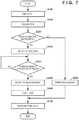
- FIG. 7 is a flowchart of skin color measurement processing according to this embodiment. Note that the same processing steps as those in the flowchart described with reference to FIG. 4 are assigned the same step numbers, and a description thereof is omitted.
- the control unit 111 After causing the light source 116 to emit light in step S 100 , in step S 200 , the control unit 111 performs calibration as shown in FIG. 2C .
- the control unit 111 determines whether or not the calibration was successful. For example, if the measurement apparatus 110 is not accommodated in the case 208 , and the light-receiving device 119 does not receive reflected light, the control unit 111 can determine that the calibration has failed.
- the control unit 111 can determine that the calibration has failed. If it is determined that the calibration has failed, in step S 202 , the control unit 111 performs error processing. For example, the control unit 111 can notify the user that a calibration error has occurred, using the LED, the buzzer, or the like of the notification unit 114 . Also, the control unit 111 can notify the operation terminal 130 that a calibration error has occurred. After the error processing, the control unit 111 causes the light source 116 to stop emitting light, and ends the processing in FIG. 7 .
- step S 203 the control unit 111 gives a notification indicating that the calibration was successful.
- the control unit 111 can notify the user that the calibration was successful, using the LED, the buzzer, or the like of the notification unit 114 , and can also notify the operation terminal 130 that the calibration was successful.
- step S 204 the control unit 111 waits until the measurement apparatus 110 is lifted up. “Being lifted up” means that a user of the measurement apparatus 110 lifts up the measurement apparatus 110 to take it out of the case 208 .
- control unit 111 detects that the amount of light with the respective wavelengths received by the light-receiving device 119 or the spectral reflectance at the respective wavelengths obtained based on the amount of received light has become smaller than a threshold, the control unit 111 can determine that the measurement apparatus 110 has been lifted up out of the case 208 . Also, a configuration may be employed in which the measurement apparatus 110 is provided with a gyroscope (not shown), and it is detected that the measurement apparatus 110 has been lifted up out of the case 208 based on the result of output from the gyroscope. If the control unit 111 detects that the measurement apparatus 110 has been lifted up, in step S 205 , the control unit 111 notifies the operation terminal 130 that measurement is in progress.
- step S 206 the control unit 111 performs steps S 101 to S 107 in FIG. 4 , and in step S 108 , the control unit 111 causes the light source 116 to stop emitting light, and ends the processing in FIG. 7 .
- FIG. 8 shows example screens displayed on the display unit 134 of the operation terminal 130 .
- FIG. 8A shows an example screen for notifying the user of the measurement apparatus 110 that the calibration is in progress, and this screen is displayed on the display unit 134 in step S 200 in FIG. 7 .
- FIG. 8B shows an example screen for notifying the user of the measurement apparatus 110 that a calibration error has occurred, and this screen is displayed on the display unit 134 in step S 202 .
- FIG. 8C shows an example screen for notifying the user of the measurement apparatus 110 that that the calibration was successful, and this screen is displayed on the display unit 134 in step S 203 .
- FIG. 8D shows an example screen for notifying the user of the measurement apparatus 110 that the measurement is in progress, and this screen is displayed on the display unit 134 in step S 205 in FIG. 7 and while steps S 101 to S 104 and S 106 in FIG. 4 are repeatedly performed.
- FIG. 8E shows another example screen for notifying the user of the measurement apparatus 110 that the measurement is in progress, and this screen also notifies the user of the measurement region. Note that, if measurement is performed at a plurality of portions, a configuration may be employed in which measurement regions are displayed in order.
- FIG. 8F shows an example screen for notifying the user of the measurement apparatus 110 of a measurement error, and this screen is displayed on the display unit 134 in step S 107 in FIG. 4 .
- FIG. 8G shows an example screen for notifying the user of the measurement apparatus 110 that the measurement is complete, and this screen is displayed on the display unit 134 in step S 105 .
- the measurement apparatus 110 detects which of a series of measurement states the measurement apparatus 110 is in, based on the results of the light-receiving device 119 receiving light.
- the control unit 110 notifies the user of the detected state directly or via the operation terminal 130 .
- the user can readily use the measurement apparatus 110 .
- the chromaticity a* and the lightness L* are used as the determination information.
- any kind of information that enables a color change due to movement of blood to be determined can be used as the determination information.
- light with a wavelength in a range from 540 to 580 nm is absorbed by hemoglobin contained in the blood.
- the spectral reflectance and the amount of received light with respective wavelengths in the wavelength range from 540 to 580 nm, or the spectral reflectance and the amount of received light with a predetermined wavelength in the wavelength range from 540 to 580 nm may be used as the determination information, and the time at which these values begin to change in accordance with a predetermined pattern may be used as the measurement timing.
- the measurement timing is determined based on a difference between the time t and the time (t ⁇ 3), that is, a difference from the measurement result obtained in the third round prior to a certain round of the repetition of steps S 101 to S 106 in FIG. 4 .
- the two measurement results between which a difference is obtained may be any other values.
- a configuration may alternatively be employed in which the measurement timing is determined based on a temporal change itself in the determination information, rather than by obtaining a difference. For example, change information indicating a change pattern of the determination information according to a change in the skin color due to movement of blood is obtained and stored in the storage unit 112 . Then, time-series data of the measured determination information in respective time zones is compared with the change pattern indicated by the change information, and the start timing of the time zone in which the time-series data is most similar to the change pattern may be determined as the measurement timing.
- the color information is the color values of the lightness L*, the chromaticity a*, and the chromaticity b* in the L*a*b* color space, but the color information may alternatively be color values in any other kind of color space.
- the spectral reflectance at respective wavelengths may also be used as the color information.
- the color information and the determination information may be different pieces of information, or may be redundant pieces of information.
- the determination information is the lightness L* and the chromaticity a*
- the color information is the lightness L*, the chromaticity a*, and the chromaticity b*.
- the color information and the determination information are redundant pieces of information, or more specifically, the determination information is a part of the color information.
- a configuration is possible in which the lightness L* and the chromaticity a* are used as the determination information, and the spectral reflectance is used as the color information.
- the color information and the determination information are different pieces of information.
- a configuration is possible in which the spectral reflectance and the amount of received light at a predetermined wavelength are used as the determination information, and the lightness L*, the chromaticity a*, and the chromaticity b* are used as the color information.
- the color information and the determination information are different pieces of information.
- reflected light from the measurement region is received, but a configuration may alternatively be employed in which transmitted light that has passed through the measurement region is incident on the dispersion unit 118 .
- Embodiments of the present invention can also be realized by a computer of a system or apparatus that reads out and executes computer executable instructions (e.g., one or more programs) recorded on a storage medium (which may also be referred to more fully as ‘non-transitory computer-readable storage medium’) to perform the functions of one or more of the above-described embodiments and/or that includes one or more circuits (e.g., application specific integrated circuit (ASIC)) for performing the functions of one or more of the above-described embodiments, and by a method performed by the computer of the system or apparatus by, for example, reading out and executing the computer executable instructions from the storage medium to perform the functions of one or more of the above-described embodiments and/or controlling the one or more circuits to perform the functions of one or more of the above-described embodiments.
- computer executable instructions e.g., one or more programs
- a storage medium which may also be referred to more fully as ‘non-transitory computer-readable storage medium’
- the computer may comprise one or more processors (e.g., central processing unit (CPU), micro processing unit (MPU)) and may include a network of separate computers or separate processors to read out and execute the computer executable instructions.
- the computer executable instructions may be provided to the computer, for example, from a network or the storage medium.
- the storage medium may include, for example, one or more of a hard disk, a random-access memory (RAM), a read only memory (ROM), a storage of distributed computing systems, an optical disk (such as a compact disc (CD), digital versatile disc (DVD), or Blu-ray Disc (BD)TM), a flash memory device, a memory card, and the like.
Landscapes
- Physics & Mathematics (AREA)
- Spectroscopy & Molecular Physics (AREA)
- General Physics & Mathematics (AREA)
- Measuring And Recording Apparatus For Diagnosis (AREA)
Applications Claiming Priority (3)
| Application Number | Priority Date | Filing Date | Title |
|---|---|---|---|
| JP2019-053477 | 2019-03-20 | ||
| JPJP2019-053477 | 2019-03-20 | ||
| JP2019053477A JP7299726B2 (ja) | 2019-03-20 | 2019-03-20 | 肌の色の測定装置及びプログラム |
Publications (2)
| Publication Number | Publication Date |
|---|---|
| US20200300705A1 US20200300705A1 (en) | 2020-09-24 |
| US11199451B2 true US11199451B2 (en) | 2021-12-14 |
Family
ID=72515662
Family Applications (1)
| Application Number | Title | Priority Date | Filing Date |
|---|---|---|---|
| US16/808,970 Expired - Fee Related US11199451B2 (en) | 2019-03-20 | 2020-03-04 | Skin color measurement apparatus and computer-readable storage medium |
Country Status (2)
| Country | Link |
|---|---|
| US (1) | US11199451B2 (enExample) |
| JP (1) | JP7299726B2 (enExample) |
Cited By (1)
| Publication number | Priority date | Publication date | Assignee | Title |
|---|---|---|---|---|
| US12527486B2 (en) * | 2023-05-29 | 2026-01-20 | Sharp Kabushiki Kaisha | Measurement device, measurement system, and measurement method |
Families Citing this family (7)
| Publication number | Priority date | Publication date | Assignee | Title |
|---|---|---|---|---|
| JP7707522B2 (ja) | 2020-11-12 | 2025-07-15 | セイコーエプソン株式会社 | 測色装置 |
| JP7679618B2 (ja) * | 2020-11-12 | 2025-05-20 | セイコーエプソン株式会社 | 測色装置 |
| CN114485946B (zh) | 2020-11-12 | 2023-09-08 | 精工爱普生株式会社 | 测色装置 |
| JP7760237B2 (ja) | 2020-11-12 | 2025-10-27 | セイコーエプソン株式会社 | 測色装置 |
| JP7631747B2 (ja) * | 2020-11-12 | 2025-02-19 | セイコーエプソン株式会社 | 測色装置 |
| JP7753644B2 (ja) | 2021-03-04 | 2025-10-15 | セイコーエプソン株式会社 | 測色装置 |
| JP7773125B2 (ja) | 2021-10-25 | 2025-11-19 | セイコーエプソン株式会社 | 測色装置 |
Citations (14)
| Publication number | Priority date | Publication date | Assignee | Title |
|---|---|---|---|---|
| US20060094941A1 (en) * | 2004-10-29 | 2006-05-04 | Ok-Kyung Cho | Optical measurement apparatus and blood sugar level measuring apparatus using the same |
| JP3815903B2 (ja) | 1997-11-12 | 2006-08-30 | 花王株式会社 | 測色装置 |
| US20100105994A1 (en) * | 2007-03-20 | 2010-04-29 | Pioneer Corporation | Biological information measuring apparatus |
| US20130094040A1 (en) * | 2011-10-14 | 2013-04-18 | Canon Kabushiki Kaisha | Image forming apparatus |
| JP2013192651A (ja) | 2012-03-16 | 2013-09-30 | Terumo Corp | 脱水判定装置 |
| US20140058227A1 (en) * | 2011-05-26 | 2014-02-27 | Sharp Kabushiki Kaisha | Measuring device, and measuring method |
| US20140058224A1 (en) * | 2012-08-21 | 2014-02-27 | Opticks, Inc. | Systems and methods for detection of carotenoid-related compounds in biological tissue |
| US20140378779A1 (en) * | 2013-06-19 | 2014-12-25 | Zoll Medical Corporation | Analysis of skin coloration |
| US20150070694A1 (en) * | 2013-09-11 | 2015-03-12 | GM Global Technology Operations LLC | Method and system for characterizing color variation of a surface |
| US20160166150A1 (en) * | 2014-12-15 | 2016-06-16 | Samsung Electronics Co., Ltd. | Image capturing device and sensing protection device |
| US9513165B2 (en) * | 2012-10-01 | 2016-12-06 | National University Corporation Kagawa University | Spectroscopic measurement device |
| US9714900B2 (en) * | 2012-04-30 | 2017-07-25 | Mayo Foundation For Medical Education And Research | Method and apparatus for selecting wavelengths for optical measurements of a property of a molecular analyte |
| JP2018504946A (ja) | 2014-12-15 | 2018-02-22 | コーニンクレッカ フィリップス エヌ ヴェKoninklijke Philips N.V. | 毛細血管再充満時間を測るためのアプローチ |
| US20190239761A1 (en) * | 2016-09-21 | 2019-08-08 | Arizona Board Of Regents On Behalf Of Arizona State University | Systems and methods for computer monitoring of remote photoplethysmography based on chromaticity in a converted color space |
Family Cites Families (2)
| Publication number | Priority date | Publication date | Assignee | Title |
|---|---|---|---|---|
| DE69625197T2 (de) * | 1995-06-07 | 2003-09-25 | Chromatics Color Sciences International, Inc. | Verfahren und vorrichtung zum nachweis und messen von zuständen,welche die farbe beeinflussen |
| GB9907613D0 (en) | 1999-04-06 | 1999-05-26 | Huntleigh Technology Plc | Skin evaluation apparatus |
-
2019
- 2019-03-20 JP JP2019053477A patent/JP7299726B2/ja active Active
-
2020
- 2020-03-04 US US16/808,970 patent/US11199451B2/en not_active Expired - Fee Related
Patent Citations (15)
| Publication number | Priority date | Publication date | Assignee | Title |
|---|---|---|---|---|
| JP3815903B2 (ja) | 1997-11-12 | 2006-08-30 | 花王株式会社 | 測色装置 |
| US20060094941A1 (en) * | 2004-10-29 | 2006-05-04 | Ok-Kyung Cho | Optical measurement apparatus and blood sugar level measuring apparatus using the same |
| US20100105994A1 (en) * | 2007-03-20 | 2010-04-29 | Pioneer Corporation | Biological information measuring apparatus |
| US20140058227A1 (en) * | 2011-05-26 | 2014-02-27 | Sharp Kabushiki Kaisha | Measuring device, and measuring method |
| US20130094040A1 (en) * | 2011-10-14 | 2013-04-18 | Canon Kabushiki Kaisha | Image forming apparatus |
| JP2013192651A (ja) | 2012-03-16 | 2013-09-30 | Terumo Corp | 脱水判定装置 |
| US9714900B2 (en) * | 2012-04-30 | 2017-07-25 | Mayo Foundation For Medical Education And Research | Method and apparatus for selecting wavelengths for optical measurements of a property of a molecular analyte |
| US20140058224A1 (en) * | 2012-08-21 | 2014-02-27 | Opticks, Inc. | Systems and methods for detection of carotenoid-related compounds in biological tissue |
| US9513165B2 (en) * | 2012-10-01 | 2016-12-06 | National University Corporation Kagawa University | Spectroscopic measurement device |
| US20140378779A1 (en) * | 2013-06-19 | 2014-12-25 | Zoll Medical Corporation | Analysis of skin coloration |
| US20150070694A1 (en) * | 2013-09-11 | 2015-03-12 | GM Global Technology Operations LLC | Method and system for characterizing color variation of a surface |
| US20160166150A1 (en) * | 2014-12-15 | 2016-06-16 | Samsung Electronics Co., Ltd. | Image capturing device and sensing protection device |
| JP2018504946A (ja) | 2014-12-15 | 2018-02-22 | コーニンクレッカ フィリップス エヌ ヴェKoninklijke Philips N.V. | 毛細血管再充満時間を測るためのアプローチ |
| US20180271382A1 (en) * | 2014-12-15 | 2018-09-27 | Koninklijke Philips N.V. | Approach for measuring capillary refill time |
| US20190239761A1 (en) * | 2016-09-21 | 2019-08-08 | Arizona Board Of Regents On Behalf Of Arizona State University | Systems and methods for computer monitoring of remote photoplethysmography based on chromaticity in a converted color space |
Cited By (1)
| Publication number | Priority date | Publication date | Assignee | Title |
|---|---|---|---|---|
| US12527486B2 (en) * | 2023-05-29 | 2026-01-20 | Sharp Kabushiki Kaisha | Measurement device, measurement system, and measurement method |
Also Published As
| Publication number | Publication date |
|---|---|
| JP2020151245A (ja) | 2020-09-24 |
| JP7299726B2 (ja) | 2023-06-28 |
| US20200300705A1 (en) | 2020-09-24 |
Similar Documents
| Publication | Publication Date | Title |
|---|---|---|
| US11199451B2 (en) | Skin color measurement apparatus and computer-readable storage medium | |
| JP5150939B2 (ja) | 光学特性測定装置および光学特性測定方法 | |
| JP5023507B2 (ja) | 波長校正方法及び波長校正装置 | |
| JP2020151245A5 (enExample) | ||
| JP5769453B2 (ja) | 分光特性測定方法および分光特性測定装置 | |
| KR20210069944A (ko) | 노화도 추정 장치 및 방법 | |
| KR20210047540A (ko) | 항산화 센서 및 항산화 수치 측정 방법 | |
| JP5869937B2 (ja) | 細胞培養液の液面高さの測定方法および測定装置 | |
| US20190298192A1 (en) | Living body measurement apparatus and computer-readable storage medium | |
| JPWO2017179520A1 (ja) | 光学測定装置、故障判断システム、故障判断方法、および故障判断プログラム | |
| JP6992812B2 (ja) | 波長シフト補正システムおよび波長シフト補正方法 | |
| JP2006071589A (ja) | 色測定装置及び光源装置 | |
| US10839271B2 (en) | Image processing apparatus, method and storage medium | |
| JP2019170540A (ja) | 生体の測定装置及びプログラム | |
| US11428631B2 (en) | Method for measuring spectral radiation characteristics of fluorescence whitened sample, and device for measuring spectral radiation characteristics of fluorescence whitened sample | |
| JPWO2019039025A1 (ja) | 波長シフト補正システムおよび波長シフト補正方法 | |
| JP7281930B2 (ja) | 生体情報の測定装置及びプログラム | |
| JP6825631B2 (ja) | 測色装置および該方法 | |
| JP2005189217A (ja) | 分光特性測定装置 | |
| US8482796B2 (en) | Color processing apparatus and color processing method | |
| EP4286808A1 (en) | Colorimeter and chromaticity measurement method | |
| US20240248026A1 (en) | Spectral image analysis method, spectral image analysis program, and spectral image analysis device | |
| JP2019170543A (ja) | 測定装置及びプログラム | |
| JP2025091987A (ja) | 色比較方法および色比較装置 | |
| US20200372646A1 (en) | Measurement apparatus for two types of biological information and computer-readable storage medium |
Legal Events
| Date | Code | Title | Description |
|---|---|---|---|
| FEPP | Fee payment procedure |
Free format text: ENTITY STATUS SET TO UNDISCOUNTED (ORIGINAL EVENT CODE: BIG.); ENTITY STATUS OF PATENT OWNER: LARGE ENTITY |
|
| AS | Assignment |
Owner name: CANON KABUSHIKI KAISHA, JAPAN Free format text: ASSIGNMENT OF ASSIGNORS INTEREST;ASSIGNOR:SAIKI, TOMOYUKI;REEL/FRAME:053044/0878 Effective date: 20200227 |
|
| STPP | Information on status: patent application and granting procedure in general |
Free format text: NON FINAL ACTION MAILED |
|
| STPP | Information on status: patent application and granting procedure in general |
Free format text: RESPONSE TO NON-FINAL OFFICE ACTION ENTERED AND FORWARDED TO EXAMINER |
|
| STPP | Information on status: patent application and granting procedure in general |
Free format text: NOTICE OF ALLOWANCE MAILED -- APPLICATION RECEIVED IN OFFICE OF PUBLICATIONS |
|
| STPP | Information on status: patent application and granting procedure in general |
Free format text: DOCKETED NEW CASE - READY FOR EXAMINATION |
|
| STPP | Information on status: patent application and granting procedure in general |
Free format text: NOTICE OF ALLOWANCE MAILED -- APPLICATION RECEIVED IN OFFICE OF PUBLICATIONS |
|
| STPP | Information on status: patent application and granting procedure in general |
Free format text: PUBLICATIONS -- ISSUE FEE PAYMENT RECEIVED |
|
| STPP | Information on status: patent application and granting procedure in general |
Free format text: PUBLICATIONS -- ISSUE FEE PAYMENT VERIFIED |
|
| STCF | Information on status: patent grant |
Free format text: PATENTED CASE |
|
| FEPP | Fee payment procedure |
Free format text: MAINTENANCE FEE REMINDER MAILED (ORIGINAL EVENT CODE: REM.); ENTITY STATUS OF PATENT OWNER: LARGE ENTITY |
|
| LAPS | Lapse for failure to pay maintenance fees |
Free format text: PATENT EXPIRED FOR FAILURE TO PAY MAINTENANCE FEES (ORIGINAL EVENT CODE: EXP.); ENTITY STATUS OF PATENT OWNER: LARGE ENTITY |
|
| STCH | Information on status: patent discontinuation |
Free format text: PATENT EXPIRED DUE TO NONPAYMENT OF MAINTENANCE FEES UNDER 37 CFR 1.362 |