US11167086B2 - Stabilized pen injector - Google Patents

Stabilized pen injector Download PDF

Info

Publication number
US11167086B2
US11167086B2 US15/983,818 US201815983818A US11167086B2 US 11167086 B2 US11167086 B2 US 11167086B2 US 201815983818 A US201815983818 A US 201815983818A US 11167086 B2 US11167086 B2 US 11167086B2
Authority
US
United States
Prior art keywords
injector
needle
optionally
syringe
adhesive
Prior art date
Legal status (The legal status is an assumption and is not a legal conclusion. Google has not performed a legal analysis and makes no representation as to the accuracy of the status listed.)
Active, expires
Application number
US15/983,818
Other versions
US20180311437A1 (en
Inventor
Oz Cabiri
Ran HEZKIAHU
Current Assignee (The listed assignees may be inaccurate. Google has not performed a legal analysis and makes no representation or warranty as to the accuracy of the list.)
West Pharma Services IL Ltd
Original Assignee
West Pharma Services IL Ltd
Priority date (The priority date is an assumption and is not a legal conclusion. Google has not performed a legal analysis and makes no representation as to the accuracy of the date listed.)
Filing date
Publication date
Priority claimed from PCT/US2009/056778 external-priority patent/WO2010030965A2/en
Priority claimed from US14/186,403 external-priority patent/US9427529B2/en
Priority claimed from PCT/US2014/058456 external-priority patent/WO2015048803A2/en
Application filed by West Pharma Services IL Ltd filed Critical West Pharma Services IL Ltd
Priority to US15/983,818 priority Critical patent/US11167086B2/en
Assigned to West Pharma. Services IL, Ltd. reassignment West Pharma. Services IL, Ltd. ASSIGNMENT OF ASSIGNORS INTEREST (SEE DOCUMENT FOR DETAILS). Assignors: CABIRI, OZ, HEZKIAHU, RAN
Publication of US20180311437A1 publication Critical patent/US20180311437A1/en
Priority to US17/514,429 priority patent/US20220047813A1/en
Application granted granted Critical
Publication of US11167086B2 publication Critical patent/US11167086B2/en
Active legal-status Critical Current
Adjusted expiration legal-status Critical

Links

Images

Classifications

    • AHUMAN NECESSITIES
    • A61MEDICAL OR VETERINARY SCIENCE; HYGIENE
    • A61MDEVICES FOR INTRODUCING MEDIA INTO, OR ONTO, THE BODY; DEVICES FOR TRANSDUCING BODY MEDIA OR FOR TAKING MEDIA FROM THE BODY; DEVICES FOR PRODUCING OR ENDING SLEEP OR STUPOR
    • A61M5/00Devices for bringing media into the body in a subcutaneous, intra-vascular or intramuscular way; Accessories therefor, e.g. filling or cleaning devices, arm-rests
    • A61M5/178Syringes
    • A61M5/20Automatic syringes, e.g. with automatically actuated piston rod, with automatic needle injection, filling automatically
    • AHUMAN NECESSITIES
    • A61MEDICAL OR VETERINARY SCIENCE; HYGIENE
    • A61MDEVICES FOR INTRODUCING MEDIA INTO, OR ONTO, THE BODY; DEVICES FOR TRANSDUCING BODY MEDIA OR FOR TAKING MEDIA FROM THE BODY; DEVICES FOR PRODUCING OR ENDING SLEEP OR STUPOR
    • A61M5/00Devices for bringing media into the body in a subcutaneous, intra-vascular or intramuscular way; Accessories therefor, e.g. filling or cleaning devices, arm-rests
    • A61M5/178Syringes
    • A61M5/31Details
    • A61M5/32Needles; Details of needles pertaining to their connection with syringe or hub; Accessories for bringing the needle into, or holding the needle on, the body; Devices for protection of needles
    • A61M5/3202Devices for protection of the needle before use, e.g. caps
    • AHUMAN NECESSITIES
    • A61MEDICAL OR VETERINARY SCIENCE; HYGIENE
    • A61MDEVICES FOR INTRODUCING MEDIA INTO, OR ONTO, THE BODY; DEVICES FOR TRANSDUCING BODY MEDIA OR FOR TAKING MEDIA FROM THE BODY; DEVICES FOR PRODUCING OR ENDING SLEEP OR STUPOR
    • A61M5/00Devices for bringing media into the body in a subcutaneous, intra-vascular or intramuscular way; Accessories therefor, e.g. filling or cleaning devices, arm-rests
    • A61M5/178Syringes
    • A61M5/31Details
    • A61M5/32Needles; Details of needles pertaining to their connection with syringe or hub; Accessories for bringing the needle into, or holding the needle on, the body; Devices for protection of needles
    • A61M5/3287Accessories for bringing the needle into the body; Automatic needle insertion
    • AHUMAN NECESSITIES
    • A61MEDICAL OR VETERINARY SCIENCE; HYGIENE
    • A61MDEVICES FOR INTRODUCING MEDIA INTO, OR ONTO, THE BODY; DEVICES FOR TRANSDUCING BODY MEDIA OR FOR TAKING MEDIA FROM THE BODY; DEVICES FOR PRODUCING OR ENDING SLEEP OR STUPOR
    • A61M5/00Devices for bringing media into the body in a subcutaneous, intra-vascular or intramuscular way; Accessories therefor, e.g. filling or cleaning devices, arm-rests
    • A61M5/42Devices for bringing media into the body in a subcutaneous, intra-vascular or intramuscular way; Accessories therefor, e.g. filling or cleaning devices, arm-rests having means for desensitising skin, for protruding skin to facilitate piercing, or for locating point where body is to be pierced
    • A61M5/425Protruding skin to facilitate piercing, e.g. vacuum cylinders, vein immobilising means
    • AHUMAN NECESSITIES
    • A61MEDICAL OR VETERINARY SCIENCE; HYGIENE
    • A61MDEVICES FOR INTRODUCING MEDIA INTO, OR ONTO, THE BODY; DEVICES FOR TRANSDUCING BODY MEDIA OR FOR TAKING MEDIA FROM THE BODY; DEVICES FOR PRODUCING OR ENDING SLEEP OR STUPOR
    • A61M5/00Devices for bringing media into the body in a subcutaneous, intra-vascular or intramuscular way; Accessories therefor, e.g. filling or cleaning devices, arm-rests
    • A61M5/178Syringes
    • A61M5/20Automatic syringes, e.g. with automatically actuated piston rod, with automatic needle injection, filling automatically
    • A61M2005/2006Having specific accessories
    • A61M2005/2013Having specific accessories triggering of discharging means by contact of injector with patient body
    • AHUMAN NECESSITIES
    • A61MEDICAL OR VETERINARY SCIENCE; HYGIENE
    • A61MDEVICES FOR INTRODUCING MEDIA INTO, OR ONTO, THE BODY; DEVICES FOR TRANSDUCING BODY MEDIA OR FOR TAKING MEDIA FROM THE BODY; DEVICES FOR PRODUCING OR ENDING SLEEP OR STUPOR
    • A61M2207/00Methods of manufacture, assembly or production
    • AHUMAN NECESSITIES
    • A61MEDICAL OR VETERINARY SCIENCE; HYGIENE
    • A61MDEVICES FOR INTRODUCING MEDIA INTO, OR ONTO, THE BODY; DEVICES FOR TRANSDUCING BODY MEDIA OR FOR TAKING MEDIA FROM THE BODY; DEVICES FOR PRODUCING OR ENDING SLEEP OR STUPOR
    • A61M5/00Devices for bringing media into the body in a subcutaneous, intra-vascular or intramuscular way; Accessories therefor, e.g. filling or cleaning devices, arm-rests
    • A61M5/178Syringes
    • A61M5/31Details
    • A61M5/32Needles; Details of needles pertaining to their connection with syringe or hub; Accessories for bringing the needle into, or holding the needle on, the body; Devices for protection of needles
    • A61M5/3202Devices for protection of the needle before use, e.g. caps
    • A61M5/3204Needle cap remover, i.e. devices to dislodge protection cover from needle or needle hub, e.g. deshielding devices
    • AHUMAN NECESSITIES
    • A61MEDICAL OR VETERINARY SCIENCE; HYGIENE
    • A61MDEVICES FOR INTRODUCING MEDIA INTO, OR ONTO, THE BODY; DEVICES FOR TRANSDUCING BODY MEDIA OR FOR TAKING MEDIA FROM THE BODY; DEVICES FOR PRODUCING OR ENDING SLEEP OR STUPOR
    • A61M5/00Devices for bringing media into the body in a subcutaneous, intra-vascular or intramuscular way; Accessories therefor, e.g. filling or cleaning devices, arm-rests
    • A61M5/178Syringes
    • A61M5/31Details
    • A61M5/32Needles; Details of needles pertaining to their connection with syringe or hub; Accessories for bringing the needle into, or holding the needle on, the body; Devices for protection of needles
    • A61M5/3205Apparatus for removing or disposing of used needles or syringes, e.g. containers; Means for protection against accidental injuries from used needles
    • A61M5/321Means for protection against accidental injuries by used needles
    • A61M5/3243Means for protection against accidental injuries by used needles being axially-extensible, e.g. protective sleeves coaxially slidable on the syringe barrel
    • A61M5/326Fully automatic sleeve extension, i.e. in which triggering of the sleeve does not require a deliberate action by the user
    • YGENERAL TAGGING OF NEW TECHNOLOGICAL DEVELOPMENTS; GENERAL TAGGING OF CROSS-SECTIONAL TECHNOLOGIES SPANNING OVER SEVERAL SECTIONS OF THE IPC; TECHNICAL SUBJECTS COVERED BY FORMER USPC CROSS-REFERENCE ART COLLECTIONS [XRACs] AND DIGESTS
    • Y10TECHNICAL SUBJECTS COVERED BY FORMER USPC
    • Y10TTECHNICAL SUBJECTS COVERED BY FORMER US CLASSIFICATION
    • Y10T29/00Metal working
    • Y10T29/49Method of mechanical manufacture
    • Y10T29/49826Assembling or joining

Definitions

  • the present invention in some embodiments thereof, relates to a medical injector and, more particularly, but not exclusively, to an injector stabilized for an extended bolus delivery.
  • a guiding assembly for an injection device comprising a mount adapted to receive an injection device, a first gripping member rotatably coupled to the mount, a first lateral stop member coupled to the first gripping member, and a spring biasing the first gripping member in a first angular position.
  • U.S. Patent Application Publication No. 2011/0166509 to Gross and Cabiri discloses an apparatus for use with tissue of a subject, including a substance configured to be injected into the tissue, and first and second tissue-squeezing surfaces configured to be placed on first and second sides of the tissue, to exert pressure on the tissue by being moved toward each other in response to a squeezing force (F), and to facilitate injection of the substance into the tissue by releasing the substance in response to application of the squeezing force.
  • F squeezing force
  • U.S. Patent Application Publication. No. 2012/0130344 to Ebbett discloses a skin gripping means for use with an injector.
  • the skin gripping means is a needle guard.
  • An exterior surface of the skin gripping means is provided with a plurality of fingers adapted to engage a subject's skin when in use.
  • a method of performing a subcutaneous injection is also disclosed with includes the steps of bringing a skin gripping means of an injector into contact with the skin of a subject, moving the skin gripping means substantially parallel to the skin to thereby form a fold in the skin, moving a needle of the injector into the fold to a suitable position for a subcutaneous injection and injecting a substance through the needle.
  • U.S. Pat. No. 8,267,890 to Alchas discloses a medication delivery device, particularly an intradermal delivery device, having a needle cannula, with a sharpened distal end having a forward tip, and a limiter disposed about the needle cannula.
  • the limiter has a distal end defining a skin engaging surface which is disposed transversely to, and at least partially about, the needle cannula.
  • the skin engaging surface is generally non-flat with generally coplanar portions, and a recess being defined in the skin engaging surface which defines a void in or adjacent to the coplanar portions into which portions of a patient's skin can be deformed into when the skin engaging surface is pressed against the patient's skin.
  • the forward tip of the needle cannula is spaced apart from a plane defined by the coplanar portions a distance ranging from about 0.5 mm to 3.0 mm such that the skin engaging surface limits penetration of the forward tip of the needle cannula to the dermis layer of the patient's skin.
  • an autoinjector comprising: a syringe including: a drug container, a hollow needle rigidly connected to a distal end of the drug container, the hollow needle in fluid communication with an interior of the drug container and a plunger sealing a proximal opening of the drug container; a driver for driving the plunger distally along an axis of the drug container thereby discharging a contents of the drug container through the needle into a patient; and an adhesive base having an aspect ratio of a long axis to a short axis of at least 1.5 to 1; the adhesive base being attached movably to the hollow needle for moving hollow needle axially through a needle hole of the adhesive base and orienting an axis of the drug container at an angle between 60 to 120 to the base during operation of the autoinjector.
  • a height of the autoinjector is at least the length of the short axis of the base.
  • an adhesive strength the adhesive base is small enough to be pivoted off a skin of a patient with ripping the skin when the autoinjector is pivoted around a pivoting axis perpendicular to a short axis of the base.
  • the hollow needle has a principle longitudinal axis substantially parallel to the axis of the drug container.
  • the autoinjector further comprises a flexible adhesive skirt extending beyond at least one edge of the adhesive base and where the flexible adhesive skirt extends in a direction of a short axis of the adhesive base further from the at least one edge of the adhesive base than from a second edge of the adhesive base.
  • the autoinjector further comprises a needle aperture in the adhesive base offset from the at least one edge toward the second edge.
  • the at least one edge and the second edge are substantially perpendicular to the short axis.
  • the hollow needle is oriented toward the at least one edge at an angle between 85 and 99 degrees of the base.
  • the autoinjector further comprises a needle cover for the hollow needle; and a handle connected the needle cover such that a linear movement of the handle pulls the needle over out a needle aperture of the base.
  • the autoinjector further comprises an adhesive cover for the adhesive base connected to the handle by an extender for peeling the adhesive cover from the base upon the linear movement of the handle.
  • the adhesive base is located distal to all of the needle cover.
  • the autoinjector further comprises a needle protection sheath configured to protrude distally from the autoinjector surrounding the hollow needle.
  • a method of injecting a substance into a patient comprising: fastening a base of the injector to a skin of the patient; moving a syringe axially with respect to the base to insert a needle of the syringe through a needle aperture in the base into the patient; discharging the substance from the syringe through the needle into the patient while the injector remains fastened to the patient; pivoting the injector around an axis along the skin to unfasten the base from the patient.
  • base has an aspect ratio of a long axis to a short axis of at least 1.5 to 1 and wherein the pivoting is around the axis substantially perpendicular to a short axis of the base.
  • the pivoting is around the axis is along an edge of the base.
  • the base includes a flexible adhesive skirt extending beyond at least one edge of the base and wherein the pivoting is around the axis opposite an opposite edge of the base and wherein the skirt extends less beyond the opposite edge than and extent of the base beyond the at least one edge.
  • a method of manufacture of a stabilized autoinjector comprising: installing a syringe rigidly attached to a sterile needle and needle cover into a pen injector having an adhesive base; and attaching a cover remover to the needle cover through an aperture in the adhesive base.
  • the method further comprises packaging the stabilized autoinjector for shipping to a patient after the installing and attaching.
  • the needle cover is located entirely on one side of the adhesive base.
  • the syringe includes a plunger sealing a proximal opening thereof and wherein the installing includes inserting the syringe into a channel in a distal assembly of the autoinjector, the distal assembly including the adhesive base on a distal end thereof and further comprising: joining the plunger to a transmission and motor for discharging medicine from the syringe by driving the plunger distally into the syringe, the joining by attaching a proximal assembly to the distal assembly.
  • the attaching includes uniting the distal assembly and the proximal assembly by an axial motion.
  • a stabilizer for an autoinjector including housing including a distal surface and a side surface, the autoinjector also including a protective needle sleeve extending distally from the autoinjector, the stabilizer comprising: a connector for attaching to the side surface of the autoinjector; and a fastener for attaching a base of the stabilizer to a skin of a patient the connector configured for holding the housing of the autoinjector in a fixed spatial relation to the fastener; a needle aperture in the base, the needle aperture being large enough for the sleeve to extend through the aperture.
  • the base has an aspect ratio of a long axis to a short axis of at least 1.5 to 1.
  • the stabilizer further comprises a flexible adhesive skirt extending beyond at least one edge of the base and wherein the flexible adhesive skirt extends in a direction of a short axis of the base further from the at least one edge of the base than from a second edge of the base.
  • the stabilizer further comprises a needle aperture in the base offset from the at least one edge toward the second edge.
  • the at least one edge and the second edge are substantially perpendicular to the short axis.
  • the stabilizer further comprises a needle cover for preserving a sterility of a hollow needle of the autoinjector; and a handle connected the needle cover such that a linear movement of the handle pulls the needle cover out the needle aperture.
  • the stabilizer further comprises a cover for the base connected to the handle by an extender for peeling the cover from the base upon the linear movement of the handle.
  • the base is located distal to all of the needle cover.
  • an article of manufacture for stabilizing an autoinjector comprising: a fastener for attachment to an injection site of a patient; and a connector for axially reversible attaching to a housing of the autoinjector, the connector configured for contacting an area of less than 4 cm 2 of the housing and wherein the connector is configured to reversibly hold the housing in a fixed orientation to the fastener.
  • the area of the house includes at least one location at least 1 mm distant from a distal surface of the autoinjector.
  • the connector includes a cavity for enclosing a portion of the autoinjector.
  • the fastener includes an adhesive surface.
  • the adhesive surface has a surface area on at least 2 cm 2 .
  • the contacting area is on a side of the autoinjector.
  • a method of retrofitting for stabilized operation an autoinjector configured for discharging of medicine to a skin of a patient contacting a distal surface of the autoinjector comprising: connecting a surface of an external housing of the autoinjector to a stabilizing adapter, the surface including at least one location not on a side surface of the housing; and supplying the autoinjector to a patient after the connecting before fastening the stabilizing adapter to patient.
  • the method further comprises packaging the autoinjector for shipment after the connecting.
  • the method further comprises enclosing a portion of the autoinjector in the adaptor.
  • the autoinjector includes a syringe rigidly attached to a sterile needle and needle cover and wherein the adaptor includes an adhesive base the method further comprising: attaching a cover remover to the needle cover through an aperture in the adhesive base.
  • the needle cover is located entirely on one side of the adhesive base.
  • a drug delivery device comprising: a preloaded syringe; including a sterile hollow needle, a barrel in fluid communication with the sterile hollow needle, a distal end of the barrel rigidly attached to the sterile hollow needle, a plunger glidingly sealing a proximal end of the barrel, the plunger sliding distally thereby discharging a contents of the barrel out the hollow needle and a flange at a proximal end of the barrel; a proximal housing portion including a motor assembly and a transmission converting a rotation motion of the motor assembly to a linear motion; a distal housing portion including a channel fitting the preloaded syringe, the channel including a distal opening large enough for inserting the syringe into the channel a proximal opening large enough to allow the hollow needle to protrude from a proximal end of the proximal housing portion; and an adhesive base for fastening the
  • the drug delivery device further comprises a mechanical connector for fastening the distal housing portion to the proximal housing portion.
  • the motor assembly includes: a support structure connectable to the proximal housing portion, a motor rigidly attached to the support structure, a power source rigidly attached to the support structure and a syringe position sensor rigidly attached to the support structure; the syringe position sensor controlling an electrical connection between the power source and the motor.
  • the preloaded syringe includes a needle cover preserving sterility of the sterile needle and the distal housing portion includes an activation device including a handle accessible from outside the channel an attachment mechanism, exposed to the channel such that when the preloading syringe is fully inserted into the channel, the attachment mechanism attaches to the needle cover a coupler passing through a needle aperture in the adhesive base, the coupler connecting the handle to the attachment mechanism.
  • an adhesive cover for the adhesive base connected to the handle by an extender for peeling the adhesive cover from the base.
  • the adhesive base is located distal to all of the needle cover.
  • the distal housing portion further includes a biasing mechanism pushing the syringe distally to a disengaged position.
  • the adhesive base has an aspect ratio of a long axis to a short axis of at least 1.5 to 1.
  • the needle has a principle longitudinal axis substantially parallel to an axis of the barrel.
  • the drug delivery device further comprises a flexible adhesive skirt extending beyond at least one edge of the adhesive base and where the flexible adhesive skirt extends in a direction of a short axis of the adhesive base further from the at least one edge of the adhesive base than from a second edge of the adhesive base.
  • the drug delivery device further comprises a needle aperture in the adhesive base offset from the at least one edge toward the second edge.
  • the at least one edge and the second edge are substantially perpendicular to the short axis.
  • the needle is oriented toward the at least one edge at an angle between 85 and 99 degrees of the base.
  • a method of manufacture of an autoinjector comprising; supplying a preloaded syringe, a preassembled distal housing portion including a channel for insertion of the preloaded syringe and a proximal housing member including a motor and a transmission; sliding the preloaded syringe longitudinally through an opening in a proximal end of the distal housing member into the channel; joining by an axial motion a distal end the proximal housing portion to a proximal end of the distal housing portion thereby connecting the transmission to a plunger of the preloaded syringe.
  • the preloaded syringe includes a sterile needle and needle cover and the distal housing member includes an adhesive base on a distal end thereof, and the method further comprises attaching a cover remover to the needle cover through an aperture in the adhesive base.
  • the needle cover is located entirely on one side of the adhesive base.
  • the adhesive base includes an adhesive cover
  • the method further includes connecting the cover remover to the adhesive cover such that removing the needle cover also peels the adhesive cover from the adhesive base.
  • FIG. 1 is a flowchart illustrating a method of stabilizing a needle in a patient in accordance with an embodiment of the present invention
  • FIG. 2 is a flowchart illustrating a method of injecting a substance in accordance with an embodiment of the present invention
  • FIG. 3 is a state diagram of an injector in accordance with an embodiment of the present invention.
  • FIGS. 4A-C are schematic illustrations of a stabilized injector in accordance with an embodiment of the present invention.
  • FIG. 5 is a schematic illustration of a needle stabilizer in accordance with an embodiment of the present invention.
  • FIGS. 6A-F are detailed illustrations of a stabilized injector in accordance with an embodiment of the present invention.
  • FIGS. 7A-K are detailed illustrations of an alternative stabilized injector in accordance with an embodiment of the present invention.
  • FIG. 8 is a flow chart illustration of a method of manufacture of a stabilized pen injector in accordance with an embodiment of the present invention.
  • FIG. 9 illustrates an external view of a stabilized injector in accordance with an embodiment of the current invention.
  • FIG. 10A-D are crossectional views illustrating a microswitch activator for an autoinjector in accordance with some embodiments of the current invention.
  • FIG. 11 is a flowchart illustration of a method of stabilizing an autoinjector in accordance with some embodiments of the current invention.
  • FIG. 12 is a state diagram of an autoinjector and extending adaptor in accordance with some embodiments of the current invention.
  • FIG. 13 is a block diagram of an autoinjector and a stabilizing adaptor in accordance with some embodiments of the current invention
  • FIGS. 14A-F is a perspective view and schematic cross sectional views of various states of an adhesive and ring stabilizing adaptor and autoinjector in accordance with some embodiments of the current invention.
  • FIG. 15 is a schematic cross sectional illustration of a friction fitting for stabilizing an autoinjector in accordance with some embodiments of the current invention.
  • FIG. 16 is a perspective view of an adjustable angled stabilizing adaptor in accordance with some embodiments of the current invention.
  • FIG. 17 is a perspective view of a stabilizing adaptor and autoinjector with a strap fastener in accordance with some embodiments of the current invention.
  • FIG. 18 is an illustration of a stabilizing adaptor with threaded connector in accordance with some embodiments of the current invention.
  • FIGS. 19A ,B are a schematic cross sectional illustrations and a perspective illustration of a stabilizing adapter in accordance with some embodiments of the current invention.
  • FIGS. 20A ,B are schematic cross sectional illustrations of a stabilizing adapter in accordance with some embodiments of the current invention.
  • FIG. 21 is a schematic cross sectional of a multipronged adapter and autoinjector in accordance with an embodiment of the current invention.
  • FIG. 22 is a flowchart illustrating a method of manufacture of a compound device in accordance with an embodiment of the present invention.
  • FIGS. 23A-D illustrate a needle cover and an injector safety cover including a needle cover remover in accordance with an embodiment of the present invention
  • FIGS. 24A-G illustrate a modular stabilized injector in accordance with an embodiment of the present invention
  • FIG. 25 illustrates a modular stabilized injector in accordance with an embodiment of the present invention
  • FIG. 26 is a flow chart illustrating a method of manufacture of a modular preloaded stabilized drug delivery device in accordance with an embodiment of the current invention
  • FIG. 27 is a flow chart illustrating a method of retrofitting a pen injector in accordance with an embodiment of the current invention
  • FIGS. 28A-C illustrate removing a stabilized pen injector in accordance with an embodiment of the current invention
  • FIGS. 29A-B illustrate a stabilizing adaptor having a large needle aperture in accordance with an embodiment of the current invention
  • FIGS. 30A-B illustrate a stabilizing adaptor which allows an injector to be removed from the adapter axially in accordance with an embodiment of the current invention
  • FIG. 31 illustrates pen injector 1400 retrofit with stabilizing adaptor 1627 packaged for distribution in accordance with an embodiment of the current invention.
  • the present invention in some embodiments thereof, relates to a medical injector and, more particularly, but not exclusively, to an injector for an extended bolus delivery.
  • An aspect of some embodiments of the present invention relates to an autoinjector and/or pen injector with stabilization.
  • Stabilization may include for example fastening and/or adhering the injector to the skin of a patient.
  • a stabilized injector may perform injections of larger volumes and/or larger time lengths than a conventional pen injector.
  • a pen injector may include a pre-sterilized fluid path.
  • the fluid path may be inserted into the injector in a sterile and/or protected condition.
  • a protective cover for the fluid path may be removed by an end user.
  • the fluid path may be very simple.
  • the fluid path may include a straight needle directly and/or rigidly connected to a drug container.
  • the needle may be in fluid communication with the drug container, for example as in a standard hypodermic syringe.
  • the needle may have a sterile cover.
  • the needle cover may for example include a standard needle cover.
  • the needle may be coaxial to the drug container. Alternatively or additionally the needle may be mounted of center of the drug container.
  • Some embodiments of the invention may include a standard straight needle. Alternatively or additionally, the needle may be bent and/or curved.
  • the needle cover may not protect the sterility of the needle. For example the entire injector or a portion thereof may be sterilized.
  • a stabilized auto injector may include a skin fastener, for example an adhesive, to increase stability of the injector.
  • the fastener may hold and/or assist the user to hold the activation zone of the injector and/or the injection zone and/or a needle aperture and/or a needle stable with respect to the skin of the patient.
  • the pen injector may include and/or perform some or all of the functions of a syringe stabilizer and/or a needle positioner, for example as mentioned herein below.
  • the payload of the syringe may include, for example between 0.5 and 2 ml and/or between 2 and 4 ml and/or between 4 and 5 ml of a drug and/or more.
  • the injector may discharge the entire payload as a single dose.
  • a pen injector may include an internally powered driver to drive the plunger and/or discharge the payload.
  • an internally powered injector driver may be defined as a drive mechanism powered by energy stored at least temporarily within the injector.
  • Power may be stored in a power supply, for instance as chemical potential (for example a chemical that produces an expanding gas and/or a battery) and/or mechanical potential (for example stored in an elastic member and/or a spring and/or a pressurized gas).
  • chemical potential for example a chemical that produces an expanding gas and/or a battery
  • mechanical potential for example stored in an elastic member and/or a spring and/or a pressurized gas.
  • the driver may be designed to discharge the payload over a time period ranging between 20 and 120 seconds and/or between 120 and 600 seconds and/or longer.
  • discharge may be driven by a driver.
  • An internally powered driver may be powered by various mechanisms including for example a motor (including for example a DC motor, an actuator, a brushless motor) and/or a transmission including for example a telescoping assembly and/or a threaded element and/or a gear and/or a coupling and/or an elastic mechanism (for example a spring and/or a rubber band) and/or an expanding gas and/or a hydraulic actuator).
  • a motor including for example a DC motor, an actuator, a brushless motor
  • a transmission including for example a telescoping assembly and/or a threaded element and/or a gear and/or a coupling and/or an elastic mechanism (for example a spring and/or a rubber band) and/or an expanding gas and/or a hydraulic actuator).
  • a pen injector in accordance with some embodiments of the current invention may include a medicine container.
  • a medicine container may be a standard type syringe.
  • a standard type syringe may be preloaded with medicine using standard equipment and/or in an aseptic room.
  • a preloaded standard type syringe may optionally include a proximal opening.
  • a plunger may optionally seal the proximal opening and/or protect the sterility of the contents of the syringe.
  • a sterile needle (for example a hollow needle) may optionally be connected to the syringe barrel.
  • the hollow of the needle may be in fluid communication with the interior of the barrel.
  • the needle may optionally be rigidly attached to the distal end of the barrel.
  • the sterility of all and/or part of the needle may for example be protected by a sterile cover.
  • the sterile cover may remain on the needle when the syringe is supplied and/or installed into an injector.
  • the medicine container may optionally include a cylindrical barrel rigidly attached to a needle.
  • the long axes of the needle and barrel of the syringe may be parallel and/or coaxial.
  • the needle may be mounted on the distal end of the barrel.
  • the needle point may be pointing in the distal direction.
  • a plunger may slide axially along the inside of the barrel to discharge a medicine payload.
  • the medicine may be discharged through the hollow needle.
  • An aspect ratio of the base may be defined as the ratio of the length of the longest axis of the base to the shortest axis.
  • the axis ratio may range between 1.5 to 2 and/or between 2 to 3 and/or greater than 3.
  • the height of the injector may range between half the length of the short axis of the base to the length of the short axis of the base and/or between the length of the short axis of the base to twice the length of the short axis of the base and/or greater than the twice length of the short axis of the base.
  • the height of the injector may supply leverage for pivoting the adhesive off the skin of a patient after use.
  • An aspect of some embodiments of the present invention relates to a stabilization device for a hypodermic syringe.
  • a stabilization device for a hypodermic syringe In some cases, it may be difficult for a user to manually hold a conventional syringe in a proper location and/or immobile enough and/or for long enough to complete injection. This problem may be particularly acute in home treatments where the caretaker may not be highly skilled. This problem may be particularly acute when injecting large volumes of liquid and/or for long periods of time, for example longer than 20 sec.
  • a syringe may be held stable with respect a fastener, fastened to the skin of a patient.
  • the fastener may stabilize the syringe with respect to the skin of a patient.
  • a non-skilled person may be able to hold a syringe in its proper place for a time ranging between 20 to 600 seconds and/or the syringe may be held substantially immobile with respect to the skin of a patient for a time ranging for example between 60 to 180 seconds.
  • the injector may inject of volume of drug ranging between 0.5 to 5 ml.
  • the injection may be a bolus delivery and/or extended bolus delivery and/or continuous delivery.
  • holding the injector immobile may include preventing straining the needle and/or bending the needle and/or occluding the needle and/or injury the patient in the injection site and/or moving the needle from the intended injection site for example due to shearing forces along the patient's skin and/or forces perpendicular to the patient's skin.
  • the fastener may be strong enough to prevent lateral movement of the injector (sliding along the skin of the patient) under designated design stresses.
  • the fastener may be strong enough to hold the injector to the body of the patient without additional support (for example preventing lateral movement and/or longitudinal movement (perpendicular to the skin of the patent) and/or rotational movement with respect to the patient's skin under designated design stresses.
  • the fastener may assist a user to manually hold the injector to the patient's body.
  • An aspect of some embodiments of the present invention relates to a device for positioning a needle in an intended tissue for medical injection. For example, it is sometimes desired to inject a drug into subcutaneous tissue. In some cases locating a conventional needle in the proper tissue can be difficult. For example skin can fold, wrinkle, stretch and/or deform in such a way that it is difficult to locate the correct tissue.
  • an adhesive base is used to hold the skin of a patient in a fixed position.
  • a syringe may be held in a predetermined position with respect to the base such that a needle connected to the syringe pierces the skin and enters a desired tissue.
  • a syringe may be held substantially perpendicular to a surface contacting the user's skin.
  • the syringe may be held at an angle ranging between 60° to 120° to the user's skin during injection.
  • an injection may be into subcutaneous tissue.
  • the needle length and/or needle insertion depth may range for between 3 to 12 mm.
  • an injection may be into muscle.
  • the needle length and/or needle insertion depth may range for between 16 to 25 mm.
  • An aspect of some embodiments of the present invention relates to a modular autoinjector and/or methods of construction and assembly of a parenteral drug delivery system.
  • final assembly of the autoinjector is by bringing together an Upper (proximal) Sub-assembly and/or a Lower (distal) Subassembly, and/or a pre-loaded syringe including for example a sterile needle and/or a sterile needle cover.
  • the syringe optionally contains an aseptic medicament solution.
  • the final assembly may consist of the pre-filled syringe being first installed in the Lower Subassembly in a motion along single axis.
  • the Upper Sub-assembly and Lower Sub-assembly are optionally coupled together, e.g. by mechanical snap fit assembly, in a single axial motion with the pre-filled syringe captured within.
  • the Upper Sub-assembly optionally comprises a housing, a transmission including for example coupling (for example a gear) and/or a telescoping screw assembly.
  • a motor drive and/or some and/or all associated electrical components e.g. switch, batteries and allied components, accessories, etc. are installed on an integral support structure (for example printed circuit board PCB).
  • the electrical components and/or the support structure may constitute for example a pre-fabricated Motor Drive Sub-assembly.
  • the prefabricated Motor Drive Sub-assembly can optionally be tested independently from the drug delivery system.
  • the Motor Drive Sub-assembly is optionally configured to be installed into the Upper and Lower Subassemblies co-axially, for example by means of mechanical snap fit relationships.
  • An aspect of some embodiments of the present invention relates to a mechanism to peel an adhesive protector when a safety cover is pulled off of an autoinjector.
  • the safety cover may be flexible and/or a hinged and/or may be anchored to an edge of the adhesive cover.
  • the safety cover may include a needle cover remover connected to a folded adhesive protector. As the safety cover is pulled away the pulling force may be transferred to a peeling force, peeling back the adhesive at one or more edges of the adhesive protector.
  • An aspect of some embodiments of the present invention relates to a needle safety mechanism for an autoinjector.
  • an unshielded needle may be safeguarded in response to resistance and/or a change of resistance to discharging of the injector payload.
  • a change in resistance to discharging may activate a rotary needle protector.
  • a resistance to discharging may engage a pair of threaded elements.
  • a drive may power discharging of a drug.
  • the drive may drive a relative rotation between the pair of threaded elements.
  • Relative rotation of the threaded elements may, in some embodiments, activate needle protection.
  • relative rotation of the pair of threaded elements may cause retraction of the needle.
  • a lock may hold a needle in an unshielded position.
  • the lock may optionally act as a support for a discharge driver. Increasing resistance to discharge may increase the stress on the driver. When the stress on the driver increases beyond a threshold and/or decreases beyond a threshold the lock may be released and/or the needle retracted to a safe location.
  • retraction of a needle may include pulling a needle point back into a shielded location without changing the length and/or shape of the shielding; and/or retracting may include extending the housing of the injector and/or a shield ahead of a needle point such that the needle is left in a shielded location.
  • a support for a needle assembly may include a telescoping assembly.
  • the telescoping assembly may retract the needle (for example by contracting) in response to a stress from a driver.
  • the safeguarding mechanism may include a sensor sensitive to a linear force from the driver. For example, a pushing force passes a threshold; a lock may be released moving the needle to the retracted configuration.
  • the force to insert the needle to the skin of a patient may range for example between 0.02 to 0.2 N and/or between 0.2 and 0.5 N.
  • the force required to inject the drug (for example the force on a syringe plunger) may range for example between 5 to 60 N.
  • the force required to inject the drug may depend on the injection rate and/or the viscosity of the drug and/or the syringe geometry and/or the needle dimensions.
  • a needle protection mechanism may be triggered by a linear force greater than, for example, between 10 to 60 N.
  • an autoinjector may be activated by manually pushing with enough force to insert the needle.
  • the device may then apply an injection force to inject a drug. Once the entire drug is injected and/or when there is an obstruction and/or occlusion, the injection force may rise until it passes a threshold triggering safeguarding of the needle and/or ending injection.
  • a needle safeguarding mechanism may include a sensor that is sensitive to the force.
  • the sensor may include a snap that gives way at 40 N returning the needle to the retracted position.
  • the stress to inject a medicine and/or to trigger safeguarding of a needle may include a torque.
  • injection of medicine may be driven by a plunger.
  • the plunger may optionally be driven by a threaded assembly, for example a threaded screw and/or teeth and/or a telescoping assembly.
  • the pitch of the teeth and/or an associated screw may range for example between 0.5 and 2 mm.
  • the diameter of the screw may range for example between 3 and 15 mm.
  • the torque to power injection may range for example between 0.2 and 1.0 N*cm.
  • the trigger torque (the torque at which the needle safeguarding is triggered) may range for example between to 0.5 to 2 and/or from 2 to 4 and/or from 4 to 10 N*cm.
  • a safety mechanism may include linear movement of the ranging between 5 to 15 mm.
  • movement of the safety mechanism may include extension of a needle during insertion and/or retraction of the needle and/or extensions of a safety shield and/or retraction of a safety shield.
  • a needle insertion length (for example the length of needle inserted into a patient) may range for example between 3 to 12 mm.
  • the linear movement of a plunger may range for example between 10-50 mm.
  • the length of movement of the plunger may vary for example with the volume of medicine to he injected that may range for example between 0.5 to 3 ml.
  • a sensor of a safeguarding mechanism may be sensitive to a torque.
  • the needle may be retracted when the mechanism is exposed to a twisting moment.
  • discharge may be driven by a torque.
  • the driver may apply torque to threaded element pushing a plunger.
  • the needle may be released and/or retracted and/or a needle shield may be deployed.
  • the trigger mechanism may require both a torque and a linear force. For example, requiring both a torque and a linear stress may prevent premature activation due to momentary friction.
  • an interference element (for example a snap) may provide resistance to retraction.
  • an annular ring may impede contraction of a telescoping assembly.
  • a rib may impede twisting of a support structure.
  • the stress may optionally overcome the interference element. Overcoming the interference element may for example reverts the support to a retracted configuration.
  • a stress resulting from resistance to discharge may trigger deployment of a needle shield.
  • the needle shield may optionally move to shield the needle in reaction to the increased stress.
  • the retraction mechanism may include a rotary drive.
  • threaded element may raise the needle.
  • a motor may drive a plunger injecting a drug (for example by means of a threaded plunger driving assembly).
  • the same motor may optionally rotate a second threaded assembly retracting the needle.
  • an adapter for extending the use of a drug delivery device, for example a single use autoinjector.
  • an adapter may stabilize an existing injector.
  • an adaptor may be configured to fasten an existing pen injector to an injection site of a patient and/or at a fixed orientation to the injection site.
  • stabilization may extend the use of an existing subcutaneous pen injector.
  • stabilizing a pen injector may extend use of the injector to longer injection times and/or to larger injection volumes and/or to more viscous medicines and/or to lower temperatures and/or to use by movement limited patients and/or to patients for whom it is difficult to stabilize the injector and/or hold the injector to the skin (for example extremely fat and/or flabby patients).
  • a non-stabilized pen injector may be licensed for autonomous use (without a stabilizing adapter) with a certain medicament. Under certain conditions (for example when the medicament is highly viscous for example because it cold or highly concentrated) the injection time may extend beyond the licensed maximum injection time for the unstabilized injector.
  • adding a stabilizing adaptor will extend the permissible injection time of the injector.
  • Extending the permissible injection time may, for example, allow use of the injector under the new conditions.
  • stabilization may extend use of a stabilized injector to a patient population that is limited in its ability to hold the non-stabilized injector in place.
  • stabilization will have minimal or no affect on the workings of the injector.
  • a stabilizing adaptor may be designed to allow unchanged functioning and/or operation of an existing injector. Minimizing changes in the function and/or operation of the injector may reduce the amount of testing necessary for licensing and/or marking of the stabilized injector and/or adaptor.
  • the injector may be held offset from the base of the stabilizer and/or the needle of the injector may be at an angle to the base of the stabilizer.
  • the needle location and/or the injector may be located away from an axis of pivoting for removing the stabilizer.
  • the injector and/or the needle may be pointed inward with respect to the axis of pivoting.
  • the adhesive may be peeled from the skin manually, for example like a band aid.
  • the adhesive may have a tab and/or an area of reduced tackiness for easy peeling.
  • an adaptor may extend use of an injector to new conditions.
  • a stabilized injector may be used for adapting the injector to longer injection times, higher viscosity medicine and/or larger volumes of medicine.
  • the time of injection with the adaptor may range between 15 to 20 seconds (for example for between 0.8 and 1.2 ml of fluid having a viscosity ranging between 7 to 9 cp) and/or between 20 to 30 seconds (for example for between 1.2 and 1.7 ml of fluid having a viscosity ranging between 7 to 9 cp) and/or between 30 to 60 seconds (for example for between 1.7 and 2.3 ml of fluid having a viscosity between 8 to 12 cp) and/or between 60 to 120 seconds (for example for 2.0 to 2.5 ml of fluid having a viscosity of between 16 and 40 cp) and/or between 120 seconds and 3 minutes for larger volumes and/or viscosities
  • an adaptor may include an adjustable element.
  • an adjustable element may include an elastic element and/or a spring and/or a threaded element and/or a clamp.
  • an adaptor may include a friction fitting and/or an adhesive and/or a tightenable fitting.
  • a friction fitting may include one way teeth. For example it may require less force to insert an injector into an adapter then to remove the injector from the adapter.
  • the force for removal may range between 1.5 and 3 times the force for insertion and/or the force for removal may range between Sand 6 times the force for insertion and/or the force for removal may be more than 6 times the force for insertion.
  • a friction fitting may have substantially the same resistance to insertion and/or removal of the injector.
  • an adaptor may be configured to attach to any one of a group of multiple injectors.
  • an adaptor may be configured to be attached to a specific injector, for example, HUMIRA® pen autoinjection device for subcutaneous injection of the fully human monoclonal antibody adalimumab from Abbot lab and/or Enbrel® of Amgen—injected with auto injector for treatment of moderate to severe rheumatoid arthritis, adult chronic moderate to severe plaque psoriasis and/or other pen injectors like EmberTM and/or MollyTM and/or DAITM and/or PSDITM or other models from SHL and other producers
  • an extending adaptor and/or a portion thereof may be supplied with an injector.
  • an adaptor may be supplied with the injector in a kit.
  • an adaptor may be attached to an injector and supplied as a single unit.
  • the adaptor will be attached to the injector by a supplier.
  • the adaptor may be attached to an injector by a doctor, a nurse, a pharmacist and/or another medical professional before being supplied to a patient.
  • the adaptor may be permanently attached to the injector.
  • the adaptor may be removed from the injector, for example after use.
  • the injector may be removed from the patient while the adaptor remains fastened to the patient.
  • the adaptor and/or the injector may be removed together from the patient.
  • a connector may be supplied with and/or come attached to the injector.
  • a fastener for fastening to a patient may mate with a coupling.
  • a single fastener may be configured for use with different couplers (for example to connect to different injectors).
  • an adapter may be used to stabilize a subcutaneous injector.
  • a subcutaneous injector may include a patch injector and/or a pen injector.
  • a pen injector may have a skin contact area on a base of the device, for example on a distal surface of the device.
  • a pen injector has a long axis substantially perpendicular to the surface of an injection site on the patient.
  • a pen injector has a long axis that is substantially parallel to the long axis of the injection needle.
  • a pen injector is optionally operated and/or configured to be operated with a long axis of the injector at an angle ranging between 80 to 100 degrees and/or between 60 and 120 degrees and/or between 30 and 150 degrees and/or ranging between 10 to 170 degrees to the surface of an injection site on the patient.
  • the distal surface of a pen injector may have an area ranging between 1 mm 2 to 25 mm 2 and/or between 25 mm 2 to 1 cm 2 and/or between 1 cm 2 to 2 cm 2 and/or between 2 cm 2 to 4 cm 2 and/or between 4 cm 2 to 9 cm 2 .
  • the skin contact area may surround a needle aperture on the distal surface of the device.
  • a patch injector may have a long axis parallel to the distal surface of the injector and/or parallel to an injection zone on the patient.
  • the long axis of a patch injector may for example be at an angle ranging between 80 to 100 degrees and/or between 60 and 120 degrees and/or between 30 and 150 degrees and/or ranging between 10 to 170 degrees to the long axis of an injection needle.
  • the distal surface of a patch injector may include the base of the device and/or a skin contact zone.
  • the distal surface may, for example, have an area ranging between 4 cm 2 to 50 cm 2 or more.
  • Subcutaneous injection sites may include for example an outer area of the upper arm and/or Just above and/or below the waist and/or an upper area of the buttock and/or a front of the thigh.
  • a stabilizing adaptor may surround and/or increase the skin contact area of an injector and/or a distal surface of the injector.
  • an adaptor and/or a connector may be attached to a housing of an injector at a location distanced from the distal surface of the injector.
  • the attachment location may range between 1 to 5 mm from the distal surface and/or between 5 mm and 2 cm from the distal surface and/or between 2 cm and 5 cm from the distal surface and/or more than 5 cm from the distal surface.
  • the adapter may be attached to the side walls of the injector.
  • the adaptor may fasten to the skin at the injection site and/or in an area ranging between 1 mm and 1 cm from the injection site and/or in an area ranging between 1 cm and 5 cm from the injection site and/or in an area ranging between 5 cm to 10 cm from the injection site.
  • the connector may include a cavity for enclosing a portion of the injector.
  • a distal portion of the injector may be held in the cavity.
  • the injector may be held inside the cavity by an adhesive and/or a friction element and/or an interference element and/or a magnet.
  • the cavity may be cylindrical and/or conical and/or elliptical.
  • the cavity may be fit for the shape of the outer housing of the autoinjector.
  • the cross section of the opening of the cavity may range for example between 1 mm 2 to 25 mm 2 and/or between 25 mm 2 to 1 cm 2 and/or between 1 cm 2 to 2 cm 2 and/or between 2 cm 2 to 4 cm 2 and/or between 4 cm 2 to 9 cm 2 .
  • the length of the cavity may range for example between 1 mm to 5 mm and/or between 5 mm to 20 mm and/or between 20 mm to 50 mm and/or between 50 mm to 100 mm.
  • the surface of contact between the injector and the connector may be less than 1 mm 2 (for example for a pressure fit screw or pin) and/or may range between 1 mm 2 to 4 mm 2 and/or may range between 4 mm 2 to 10 mm 2 and/or may range between 10 mm 2 to 1 cm 2 and/or may range between 1 cm 2 to 10 cm 2 and/or may be greater than 10 cm 2 .
  • an adapter may be used to stabilize an intramuscular injector.
  • an intramuscular injection site may include an area over a Deltoid Muscle and/or an area over a Vastus Lateralis Muscle and/or an area over a Ventrogluteal Muscle and/or an area over a Dorsogluteal Muscle.
  • an extending adaptor may be supplied separately from the injector.
  • the adaptor may be fastened to the patient without the injector.
  • the injector is attached to the adaptor while the adapter is still on the patient.
  • the patient and/or a medical aid may attach the adapter to the injector before fastening the adaptor to the patient.
  • an adaptor extending use of an injector may make minimal changes in the injector.
  • the adaptor may be attached to the injector in a manner that permits access to the controls of the injector.
  • the adaptor is attached to the outer housing of the injector without changing the internal operation of the injector.
  • an autoinjector that is activated by the skin contact trigger in the autonomous mode may also be activated by a skin contract trigger in the extended mode.
  • an autoinjector that is activated by push button trigger in the autonomous mode may also be activated by the push button trigger in the extended mode.
  • an adaptor may be configured to permit operation of a stabilized injector with minimal change from unstabilized autonomous operation.
  • an adaptor may permit user access to the controls of the injector in the same manner as for autonomous operation.
  • the positioning and/or operation of the injector may be within the prescribed operation and/or positioning of the injector for unstabilized operation.
  • the injector when stabilized the injector may be orientated to the patient as in autonomous operation.
  • the distal surface of the injector and/or a contact surface of the injector in autonomous operation may also contact the patient in stabilized operation.
  • distal surface and/or the contact surface may contact the adaptor in stabilized operation and/or the adaptor may contact the skin of the patient.
  • the distance between the injection site of the patient and a distal surface of the adaptor may range between 1 mm and 0.5 mm and/or between 0.5 mm and 0.1 mm and/or less than 0.1 mm.
  • An angle between the injector and the injection site of the patient in stabilized operation may within the recommended range of angles during unstabilized operation.
  • FIG. 1 illustrates a method of positioning and/or stabilizing a hypodermic needle in accordance with an embodiment 100 of the present invention.
  • an adhesive base is used to retain the skin and/or hypodermic tissue of a patient in a predicable geometry.
  • a syringe retainer holds a syringe in a predetermined position with respect to the base such that a needle mounted to the syringe penetrates the skin to reach a desired tissue.
  • a medicament may optionally be discharged to the desired tissue.
  • the syringe and/or needle may optionally be held in place for an extended period, for example, for a long injection ranging between 30 seconds and 500 seconds.
  • an injection could include a large dose for example between 0.5 and 5 ml.
  • a syringe may be attached 101 to an adhesive base.
  • the attachment may have fixed position and/or the syringe may be movable attached to the base.
  • the attached syringe may move longitudinally between a storage position wherein a needle is shielded by the base and an exposed position wherein a portion of the needle protrudes past the base.
  • the base may be adhered 120 to the skin of a patient.
  • the needle may be attached to the base either before or after adhesion 120 to the skin.
  • a needle may be inserted 102 into the skin of the patient.
  • the needle may be inserted 102 by means of a longitudinal movement pushing a portion of the needle into a deployed position point past the base (for example through a hole in the base) into the patent.
  • the syringe may be fixedly attached to the base with the needle protruding beyond the adhesive such that placing the adhesive onto the patient also inserts the needle into the patient.
  • the device may stabilize 104 in a desired position during discharge of a medicine.
  • the needle may be removed 114 from the patient and/or the adhesive base may be peeled and/or pivoted from the skin.
  • the entire device may be twisted such that one side of the adhesive is lifted and/or pivoted and/or peeled from the skin while the far edge of the base of the injector remains in contact with the skin and serves as a fulcrum.
  • FIG. 2 illustrates a method of injecting a drug in accordance with an embodiment 200 of the present invention.
  • a needle is optionally held stable while a drug is dispensed to a patient (dispensing a drug may include discharging a drug from the injector).
  • a user for example a patient and/or a medical aid in home care
  • the user may optionally remove 216 a safety cover from the injector.
  • Removing 216 the cover may optionally include removing a sterile cover from a needle.
  • Removing 216 the cover may optionally automatically peel 218 an adhesive protector from an adhesive.
  • the adhesive may be supplied to stabilize the injector on the skin of a patient during injection.
  • the injector may optionally be fastened 220 to a patient (who may be the user).
  • a user may hold the injector to the skin of a patient; the fastening 220 may stabilize the injector for example from shifts and/or movements of the patient and/or the user.
  • the user may set off an activation mechanism.
  • the activation mechanism may for example insert 202 the needle into the patient, for example by extending the needle outward.
  • a syringe may be moveably attached to the base.
  • a syringe may optionally be rigidly attached to the syringe.
  • the syringe may slide linearly along its axis. Sliding the syringe towards the base may cause the needle rigidly to protrude beyond the base.
  • part of the needle may pass through a hole in the base and pierce the skin of a patient.
  • the adhesive of the base may hold the skin of the patient steady while the needle pierces the skin.
  • the combination of an adhesive holding the skin and moving the needle to a predetermined position past the base may facilitate the inserting 202 of the needle into the skin to the desired depth.
  • the needle may optionally be locked in the extended position.
  • the needle may be biased to a protected position (for example to retract into a housing of the injector).
  • the needle may be biased to the unshielded position.
  • the autoinjector may be supplied with the needle in an extended mode and/or protected by a cover.
  • an optional manual retraction 224 mechanism may be used to place the injector in a safeguarded mode. For example, when the user decides to abort 222 a - f at a point in the process (for example when he detects some sort of malfunction and/or feels a negative reaction to the medicine) the user may manually retract 224 the needle.
  • the user may manually retract 224 the needle.
  • there may be an indicator to indicate 212 whether the needle was automatically retracted 210 and/or whether needle was manually retracted 224 .
  • the injector may optionally begin discharging 204 medicine.
  • the medicine may be injected through the needle into the patient.
  • discharge may continue until a full dose of the medicine is administered.
  • a change 206 in resistance may be a change 206 in resistance to further discharging.
  • a plunger may reach the end of the syringe and cease to move increasing resistance.
  • a transmission may be disconnected (for example a threaded element may pass the end of its threading) reducing resistance.
  • the change 206 in resistance may result from another cause for example increased resistance due to a full or partial occlusion of a fluid pathway and/or jamming of a mechanical component (for example cross threading of a screw).
  • the change of resistance may optionally be sensed 208 triggering retracting 210 of the needle.
  • the needle may be locked in an unshielded state by a force sensitive lock.
  • the lock senses 208 the change 206 in resistance, it may release 209 the needle which may be retracted 210 to a shielded position.
  • a flag may be supplied (for example a LED and/or a changing color indicator) to indicate 212 to the user that the needle has been retracted 210 and/or that the injector can safely be removed 214 from the patient and/or that a fastener has been released. For example, if the injector is adhered to the patient, it may be peeled off and/or a fastener may be released.
  • FIG. 3 is a state diagram of an autoinjector in accordance with an embodiment of the present invention.
  • An unattached 337 autoinjector may have a secured 331 state.
  • the injector may be safe to handle and/or transport.
  • the injector may have an enabled 332 state.
  • the injector in the enabled 332 state, the injector may be unstable and/or easily activated.
  • an injector may be switched from the secured 331 state to the enabled 332 state by removing a needle protector and/or an adhesive cover.
  • the injector may optionally be fastened to a patient.
  • the injected may optionally be activated.
  • a needle may project from the injector.
  • the injector may he hazardous to handle in the enabled 332 and/or active 333 state.
  • the user may want to remove and/or dispose of the autoinjector.
  • it may be difficult and/or dangerous to remove an injector in the enabled and/or active state.
  • an injector when an injector is fastened to a patient by an adhesive, it may be difficult to remove the needle by pulling the injector away from the skin.
  • a needle may be retracted from the skin into the injector.
  • the adhesive may be removal by pivoting and/or pulling and/or peeling from the skin.
  • the injector may automatically be safeguarded 335 for example by retraction of a needle upon completion of injection.
  • the user may have the option to manually secure the injector into a safeguarded 336 state.
  • the optionally of manually needle retraction may avoid the situation where a patient may not be able to properly remove the injector due to a malfunction that leaves the injector fastened to the skin with the needle inserted into the patient.
  • the injector may be removed from the patient.
  • the injector may have a final released state 339 , for example wherein the needle is retracted back into the injector and/or the needle tip is shielded and/or the injector has been unfastened from the patient.
  • one or more indicators may be supplied to indicate the state of the injector and/or the quantity of medicine discharged. Once released, the injector may he in final 314 state (protected from hazards and/or ready for disposal, for example in a municipal waste).
  • FIGS. 4A-C are schematic illustrations of a drug delivery device including a needle stabilizing mechanism that clasps the skin of a patient in accordance with an exemplary embodiment 400 of the present invention.
  • a needle 460 is biased to a retracted state for example by a spring 462 (see for example FIG. 4A ).
  • an optional clamp 443 may be biased in an open state.
  • needle 460 is optionally held in an extended state by a driver 444 and/or a medicine container 446 .
  • clamp 443 may close onto the skin of a patient holding the injector steady.
  • needle 460 may be in fluid communication with medicine container 446 .
  • driver 444 may retract and/or release medicine container 446 and/or the needle 460 .
  • driver 444 may be unlocked. Once unlocked, driver 444 may optionally revert to a retracted state and/or clamp 443 may optionally be released and/or needle 460 may optionally retract back into the housing (for example as illustrated in FIG. 4D ).
  • locking mechanism may include for example interference elements 452 a,b and/or a locking pin 456 to retain driver 444 in a retracted and/or extended position until a force is applied.
  • pin 456 may he rigidly connected to driver 444 .
  • a force may be applied to push pin 456 past interference elements 452 a,b.
  • FIG. 4A illustrates exemplary embodiment 400 in an enabled state prior to activation.
  • an optional safety cover and/or a sterile cover may and/or an adhesive protector may have been removed from the injector.
  • a needle 460 is shielded by an activation zone on a base 442 of a housing 440 .
  • Needle 460 is safeguarded by a retraction assembly including for example a spring 462 biasing the needle into housing 440 and a needle locking mechanism 458 and a driver 444 which hold needle 460 and its supporting medicine container 446 inside housing 440 .
  • FIG. 4B illustrates exemplary embodiment 400 in an activated state, for example right before and/or at the beginning of discharge of a medication.
  • embodiment 400 is activated by pushing driver 444 with a sufficient force 464 a.
  • Pushing driver 444 optionally pushes needle 460 , medicine container 446 , and/or clamp 443 from the retracted position (illustrated in FIG. 4A ) to the extended position (illustrated in FIG. 4B ). Movement may, for example, be along the primary longitudinal axis 477 of medicine container 446 .
  • needle 460 is shown coaxial to medicine container 446 . Alternatively or additional a needle may be mounted off center of a syringe.
  • clamp 443 moves from the retracted to the extended position, it closes, grasping a skin 466 of the patient.
  • driver 444 may apply a force on plunger rod 450 and/or plunger 448 to discharge medicine.
  • driver 444 may be configured to drive discharge of the medicine over a relatively long period of time, for example between 30 to 120 seconds and/or between 120 to 600 seconds.
  • FIG. 4C illustrates exemplary embodiment 400 at the end of discharge of a medicament.
  • Plunger 448 has optionally reached the end of its path.
  • a locking mechanism 458 has been released.
  • Unlocking locking mechanism 458 may optionally trigger releasing clamp 443 and/or safeguarding needle 460 .
  • FIG. 5 illustrates a drug delivery device including an adhesive syringe stabilizer 500 in accordance with an embodiment of the current invention.
  • Syringe stabilizer 500 includes a base 542 adhering to a skin of a patient.
  • a syringe 546 is attached to base 542 by means of a housing 540 .
  • Syringe 546 is rigidly connected to a needle 560 which protrudes from syringe 546 past base 542 into a skin 566 of a patient.
  • needle 560 may be in fluid communication with syringe 546 and/or the patient.
  • Needle 560 is shown in embodiment 500 mounted coaxially to syringe 546 (along the principal longitudinal axis 577 of syringe 546 ).
  • needle 560 may be mounted to the syringe off center.
  • the term principle longitudinal axis of a drug container may be used to refer to the longest axis of symmetry of the drug container.
  • an adhesive 578 may be attached to a distal surface of a base 542 .
  • a housing 540 attached to a proximal side of base 542 may optionally hold syringe 546 with a needle 560 protruding from syringe 546 across base 542 (for example through a hole in base 542 ).
  • syringe 546 may be attached to base 542 prior to adhering base 542 to a patient.
  • the entire assembly may be attached to the patent (piercing the skin 566 with needle 560 and inserting needle 560 into the skin until adhesive 578 contacts skin 566 ).
  • syringe 546 may be movably attached to housing 540 .
  • syringe 540 may slide longitudinally along housing 540 .
  • syringe 546 may be attached to housing 540 with needle 560 held proximal to base 542 . Then the distal surface of base 542 may be adhered to skin 566 . Subsequently, syringe 546 and needle 560 may be slide longitudinally in the distal direction 579 until needle 560 protrudes through base 542 into skin 566 .
  • adhesive 578 may assist a user to steady syringe 546 as he discharges medicine into the patient (for example by pushing on a plunger).
  • base 542 may first be attached to the patient. Then a user may hold syringe 546 in his hand and insert needle 560 through a hole in base 542 into the skin of the patent,
  • a possible advantage of inserting needle 560 into skin 566 after attaching base 542 to skin 566 is that adhesive 578 may inhibit deformation of skin 566 during needle insertion. This may make it easier to control the precise depth of insertion.
  • Adhesive 578 may assist a user to steady syringe 546 as he discharges medicine into the patient (for example by pushing on a plunger).
  • FIGS. 6A-D include detailed cross sectional side views illustrating four states of an autoinjector drug delivery device in accordance with an embodiment of the present invention.
  • an injector 600 is an automated self injection device.
  • the self injecting device may in some ways be similar to a pen injector.
  • injector 600 may be loaded with a standard type syringe 646 and/or hypodermic needle 660 .
  • needle 660 may be rigidly connected and/or project from a distal end of syringe 646 .
  • Needle 660 may be coaxial with syringe 646 .
  • the axis of needle 660 may be parallel to the primary longitudinal axis 677 of syringe 646 but offset therefrom.
  • Syringe may be loaded into injector 600 with needle 660 in a sterile state and/or covered by a sterile cover.
  • an injector may include for example an adhesive 678 base 642 .
  • adhesive 678 base 642 may assist a user to hold injector 600 steady on the skin of a patient for an extended period.
  • injector 600 may be used to give injections of volume ranging between 0.5 and 3.0 ml over a time period ranging between 30 sec to 180 sec.
  • Injector 600 may include a transmission.
  • the transmission may include a rotary screw converting rotational motion of a motor 676 to linear motion for sliding a plunger to discharge a drug and/or for retracting a needle.
  • linear motion of the transmission may also be used to insert a needle.
  • the transmission includes for example an annular snap resistance element 652 paired to an annular driver support 656 . When a linear stress increases past a threshold, the annular snap gives way and a needle 660 may optionally be retracted to a protected location.
  • FIG. 6A is a schematic cross sectional side view illustrating injector 600 in an enabled state (ready for activation).
  • an optional safety cover and/or a sterile cover may and/or an adhesive protector may have been removed from the injector.
  • needle 660 is in a protected location, created by a shield 641 which extends the distal end of a housing 640 of the injector. Needle 660 and/or shield 641 may optionally be retained in position, for example by a snap and/or held in position by a biasing device, for example a spring.
  • needle 660 may optionally be supported by a syringe 646 ; which is in turn supported for example by a cylindrical outer sleeve 668 .
  • Outer sleeve 668 may optionally be supported by an annular support 656 resting on an annular snap resistance element 652 .
  • annular snap resistance element 652 may extend radially outward from a cylindrical inner sleeve 667 .
  • inner sleeve 667 and/or outer sleeve 668 and/or a driver 644 may be operationally linked to a coupling 684 (for example including a gear) such that rotating coupling 684 rotates one or more of inner sleeve 667 and/or outer sleeve 668 and/or a driver 644 .
  • a coupling 684 for example including a gear
  • syringe 646 position sensor for example a motor switch 682 may be located in shield 641 . In the enabled state (before activation), switch 682 is optionally switched off.
  • syringe 646 is held to outer housing 640 by a socket 661 .
  • Socket 661 allows syringe 646 to slide axially with respect to housing 640 but not to move laterally.
  • coupling 684 is held rotatably fixed to housing 640 by bearing 659 in a hub 665 .
  • FIG. 6B is a schematic cross sectional side view illustrating injector 600 immediately after activation.
  • a user may place the distal end of the injector (including for example an adhesive 678 and/or an activation zone on base 642 ) against the skin 666 of a patient and/or push 664 on the proximal end of the injector until shield 641 collapses into housing 640 in a direction parallel to the longitudinal axis of needle 660 .
  • Collapse of shield 641 may optionally unshield needle 660 tip which may for example be pushed into the skin 666 of the patient.
  • needle 660 may protrude from injector 600 into a patient.
  • needle 660 may be in fluid communication with syringe 646 and/or the patient.
  • needle 660 may supply a fluid pathway for discharging medicine directly from syringe 646 through needle 660 into the patient.
  • switch 682 upon collapse of shield 641 senses movement of syringe 646 to the active position and/or activates motor 676 .
  • switch 682 is depressed by being pushed against syringe 646 .
  • Depressing switch 682 may activate motor 676 to power a transmission and/or linear movement of a plunger 648 for discharging a drug.
  • motor 676 turns a coupling 684 .
  • Coupling 684 may include for example a gear.
  • Coupling 684 may optionally rotate inner sleeve 667 and/or driver 644 .
  • driver 644 includes teeth and/or threads which engage a screw thread 653 on a plunger rod 650 .
  • Rotating driver 644 may optionally drive plunger rod 650 and/or plunger 648 in the distal direction, discharging the medicine.
  • plunger 648 continues to move distally until it is stopped by for example a blockage in the fluid path (preventing further discharge) and/or until plunger 648 reaches the distal end of syringe 646 .
  • a flange 647 of syringe 646 seats against a bracket 673 , which holds syringe 646 and/or prevents further longitudinal movement.
  • FIG. 6C is a schematic cross sectional side view illustrating injector 600 at the end of discharge of the payload.
  • plunger 648 has discharged all of the medicine out of syringe 646 and/or has reached the distal end of syringe 646 .
  • further rotation of driver 644 increases the stress pushing driver 644 proximally.
  • Interference element 652 may serve as stress sensor.
  • motor 676 may supply enough torque to create a force which overcomes interference element 652 .
  • a course inner threading 655 in sleeve 667 rotates with respect to a course outer thread 651 of driver 644 drawing driver 644 and/or plunger 648 and/or syringe 646 and/or needle 660 proximally into a retracted state.
  • the course thread 651 has an opposite threading from the threading 653 between driver 644 and plunger rod 650 .
  • the same direction of rotation that drives plunger 648 distally before overcoming interference element 652 also draws back plunger 648 and/or syringe 646 and/or needle 660 proximally after overcoming interference element 652 .
  • needle 660 is retracted into a protected location inside housing 640 for example as illustrated in FIG. 6D .
  • course thread 651 may have an the same direction of threading as threading 653 between driver 644 and plunger rod 650 and optionally rotation may be reversed to retract needle 660 .
  • FIG. 6D is a schematic cross sectional side view illustrating injector 600 in a safe state after finishing injection. Needle 660 point has optionally been retracted into a protected location within housing 640 . Syringe 646 has optionally been retracted. In exemplary injector 600 , switch 682 senses that syringe 646 is retracted, as syringe 646 no longer depresses switch 682 . Switch 682 may be biased off and/or raising syringe 646 may shut off motor 676 .
  • one or more windows may be supplied.
  • a user may be able to determine a status of the device by viewing for the windows.
  • injector 600 has been supplied with two windows 690 a,b.
  • window 690 a is located such that during injection, the user views inner sleeve 667 through window 690 a.
  • outer sleeve 668 has been retracted, it may optionally slide over inner sleeve 667 .
  • the user views outer sleeve 668 through window 690 a.
  • window 690 a may serve as an indicator whether it is safe to remove the injector.
  • outer sleeve 668 may be colored green and/or driver 644 and/or inner sleeve 667 may be colored red.
  • window 690 b may be used to indicate whether an entire payload of medicine has been administered.
  • syringe 646 may be made of a transparent material.
  • the user can see the medicine through window 690 b; after syringe 646 is retracted if the payload has been fully discharged then the user will view plunger 648 through window 690 b.
  • the user can ascertain that it is safe to remove the injector and/or that the drug was fully discharged.
  • the device may be twisted such that one side of the adhesive is lifted and/or pivoted and/or peeled (as illustrated by arrow 683 in FIG. 6D ) from the skin while the far edge of the base of the injector remains in contact with the skin and serves as a fulcrum.
  • FIGS. 6E and 6F illustrate an external view and cut away view respectively of a transmission for driving discharge and retracting a needle in accordance with exemplary embodiment (for example injector 600 ) of the current invention.
  • Injector 600 may optionally be designed such that, under sufficient linear stress, support 656 of external sleeve 668 deforms and/or opens to pass over resistance element 652 .
  • coupling 684 and/or inner sleeve 667 may be formed of one or more pieces of molded plastic.
  • outer sleeve 668 and/or driver 644 may be formed of one or more pieces of molded plastic.
  • FIG. 6F illustrates details of a rotary needle retractor in accordance with an embodiment of the current invention.
  • FIG. 6F illustrates driver 644 before needle retraction (for example in a secured state, an enabled state and/or an active state).
  • driver 644 is engaged by a set of fine screw threads 653 to rod 650 .
  • driver 644 is engaged by a set of course screw threads 651 , 655 to inner sleeve 667 .
  • course screw threads 651 , 655 are threaded in an opposite sense from fine screw threads 653 .
  • sleeve 667 , 668 and driver 644 prior to needle retraction, sleeve 667 , 668 and driver 644 are prevented from sliding longitudinally with respect one another. While sleeves 667 , 668 and driver 644 are prevented from relative longitudinal movement, threads 651 and 655 prevent inner sleeve 667 and driver 644 from rotating with respect to one another.
  • motor 676 drives coupling 684 to rotate inner sleeve 667 .
  • rotating inner sleeve 667 rotates driver 644 .
  • the sense of screw threads 653 and the rotating direction of motor 676 are optionally chosen such that rotating driver 644 relative to rod 650 pushes rod 650 and/or plunger 648 distally, optionally discharging a drug.
  • screw threads 655 and 651 and the rotating direction of motor 676 are optionally chosen such rotating driver 644 relative to sleeve 667 draws driver 644 and/or rod 650 and/or plunger 648 and/or syringe 646 and/or needle 660 proximally, optionally retracting needle 660 .
  • the pitch of screw threads 651 , 653 and/or 655 can be tuned to achieve a desired rate of medicine discharge and/or needle retraction for a given rotation rate of the motor.
  • friction between plunger 648 and syringe 646 draws syringe 646 and/or needle 660 proximally.
  • outer sleeve 668 may be attached to syringe 646 . Drawing back on driver 644 may draw outer sleeve 668 and syringe 646 back with it.
  • additional threaded elements may be added to produce a multi-part telescoping assembly for extending plunger 648 to discharge medicine and/or for retracting needle 660 .
  • some or all of rod 650 , inner sleeve 667 , and/or outer sleeve 668 and/or coupling 684 may be formed of molded plastic and or other materials.
  • FIGS. 7A-H illustrate a drug delivery device including a stabilized injector 700 in accordance with some embodiments of the present invention.
  • Exemplary injector 700 is an automated injection device in some ways similar to a pen injector.
  • injector 700 may be loaded with a standard type syringe 646 and/or hypodermic needle 660 .
  • syringe 646 may be supplied loaded with medicine and/or covered with a sterile needle cover 791 .
  • Syringe 646 may be loaded into injector 700 with in a sterile state with needle cover 791 in place.
  • Injector 700 may include for example an adhesive 678 base 642 .
  • adhesive 678 base 642 may assist a user to hold injector 700 steady on the skin of a patient for an extended period.
  • injector 700 may be used to give injections of volume ranging between 0.5 and 3.0 ml over a time period ranging between 30 sec to 180 sec.
  • FIG. 7A illustrates an exploded view of injector 700 .
  • Some components of the exemplary embodiment of injector 700 which are similar to corresponding parts of the exemplary embodiment of injector 600 are marked with the same number as the corresponding parts of the exemplary embodiment of injector 600 .
  • a power supply (for example batteries 770 ) may optionally supply power to gear motor 676 .
  • FIGS. 7A ,B illustrate flange 647 of syringe 646 .
  • flange 647 has at least one non-rounded edge which may be held inside an autoinjector (for example autoinjectors 400 , 600 and/or 700 ) preventing rotation of syringe 646 .
  • Outer housing 740 and/or shield 741 of injector 700 are similar to outer shell 640 and/or shield 641 of injector 600 .
  • a stabilized autoinjector may include a safety cover and/or an adhesive protector and/or a handle. Details of an exemplary embodiment of an adhesive protector 789 and/or a handle 794 and/or a needle cover remover, for example a safety cover 792 are illustrated in FIGS. 7C-H .
  • FIG. 7B illustrates an exemplary transmission including a retraction mechanism 758 .
  • Retraction mechanism 758 is optionally activated by a combination of torque and linear stress.
  • retraction mechanism 758 is optionally activated may when plunger 648 is blocked for example when it reaches the end of injection (for example as described in regards to FIGS. 6A-D and/or due to an occlusion of needle 660 ).
  • a motor for example motor 676 .
  • Coupling 684 may optionally be rigidly connected to and/or integrally molded with inner sleeve 768 .
  • Rotating coupling 684 may also rotate inner sleeve 768 .
  • a pin 756 protrudes from driver 744 into a nearly lateral slot 754 a in sleeve 768 . While pin 756 is in slot 754 a, driver 744 is prevented from moving longitudinally with respect to inner sleeve 768 .
  • syringe 646 is supported (from moving proximally) by driver 744 .
  • pin 756 and/or interference element 752 may slide longitudinally (in the proximal direction).
  • a geometry of pin 756 and/or interference element 752 may be chosen to achieve a desired resistance to movement.
  • pin 756 and/or interference element 752 may have a squared side, a flat side, a rounded side etc.
  • a spring biases syringe 646 in the proximal direction.
  • spring 762 may apply a proximal force to flange 647 .
  • another biasing element may be used in place of spring 762 .
  • a biasing element may include a stretched element (for example a rubber band and/or a twisted elements and/or a deflected plastic element).
  • needle 660 may he held in the retracted position by spring 762 .
  • a locking mechanism may be included to lock needle 660 in the retracted position, for example, a one way catch and/or an interference element may lock against syringe 646 as it is retracted and/or against pin 756 in slot 754 b.
  • driver 744 includes two molded plastic telescoping pieces.
  • sleeve 767 and/or driver 744 may be made as a single piece and/or multiple parts. They may be formed of plastic and/or another material and/or they may be molded and/or formed by another process.
  • FIGS. 7C and 7D illustrate an exemplary method of folding adhesive protector 789 .
  • adhesive protector may include three folded portions 785 a, 785 b, and 785 c.
  • adhesive protector may include three holes 787 a, 787 b, and 787 c. When folded, the side portions 785 b,c may fold over the center portion 785 a. Side holes 787 c,b may line up with center hole 787 a.
  • an adhesive protector may have only one fold and/or one side portion and/or peeling may be from one side only.
  • portion 785 a will be adhered to base 642 with the needle opening accessible through holes 787 a - c.
  • a safety cover (for example cover 792 ) may protrude through holes 787 a - c.
  • the safety cover may optionally be connected to portions 785 b,c.
  • the safety cover may pass freely through hole 787 a and/or not be connected to portion 785 a of adhesive protector 789 .
  • FIGS. 7E-H illustrate removal of an exemplary safety cover 792 , needle cover 791 and/or adhesive protector 789 .
  • safety cover 792 may prevent deployment and/or activation of the injector.
  • safety cover 792 and handle 794 may supply a convenient means of removing needle cover 791 and/or adhesive protector 789 .
  • FIG. 7E illustrates injector 700 in a safe state for storage and/or transport. Needle cover 791 , safety cover 792 and adhesive protector 789 are in place. Adhesive protector 789 is folded for example as illustrated in FIGS. 7C ,D. Needle cover 791 (not seen in the drawing) may optionally preserve the sterility of needle 660 . Safety cover 792 surrounds and grasps needle cover 791 . Safety cover 792 may prevent inadvertent activation of the injector and/or protect users from a needle stick hazard.
  • FIG. 7F illustrates the beginning of removal of safety cover 792 .
  • a user pulls handle 794 away from needle 660 .
  • Handle 794 pulls needle cover 791 out the needle hole and/or needle aperture of injector 700 and through hole 787 a.
  • portions 785 b,c of adhesive protector unfold while portion 785 a remains adhered to base 642 .
  • FIG. 7G illustrates that as safety cover is pulled further away from base 742 portions 785 b,c of adhesive protector 789 pull and/or pivot and/or peel portion 785 a away from base 742 .
  • FIG. 7H illustrates cover 792 arid protector 789 fully removed from injector 700 , such that injector 700 is enabled and/or ready to adhere to a patient and/or ready for activation.
  • FIG. 7I illustrates exemplary embodiment 71 assembled and/or in an enabled state before insertion of needle 660 into a patient.
  • FIG. 7I illustrates various optional details and/or supporting structures for syringe 646 and/or plunger.
  • syringe 646 is held to outer housing 740 by a socket 761 .
  • Socket 761 allows syringe 646 to slide axially with respect to housing 740 but not to move laterally.
  • coupling 684 is held rotatably fixed to housing 740 by bearing 759 in a hub 765 .
  • FIG. 7J illustrates exemplary injector 700 in an active state.
  • a user may place adhesive against the skin of a patient and push downward (distally) on housing 740 .
  • Housing 740 and its contents for example syringe 646 , coupling 684 , locking assembly 758 etc.
  • needle 660 are all pushed distally along the axis of needle 660 .
  • the needle tip passes through a hole in shield 741 .
  • needle 660 may protrude from injector 600 into a patient.
  • needle 660 may be in fluid communication with syringe 646 and/or the patient.
  • needle 660 may supply a fluid pathway for discharging medicine directly from syringe 646 through needle 660 into the patient.
  • Bracket 773 may optionally hold syringe 646 steady and/or prevents further longitudinal movement and/or prevent lateral movement with respect to housing 740 .
  • FIG. 7K illustrates injector 700 after needle retraction.
  • driver 644 includes a telescopic assembly, which is shown in an extended state in FIG. 7K .
  • the entire device may be twisted to pivot and/or peel adhesive 678 from the skin.
  • needle 460 and 560 of embodiment 400 and 500 are shown mounted at an angle to base 442 or 542 . Alternatively or additionally they may be perpendicular to the base.
  • needles 660 of embodiments 600 and 700 are shown perpendicular to base 642 . Alternatively or additionally they may be at an angle to the base.
  • Needle covers and/or protective covers illustrated in one embodiment may be used with another embodiment.
  • Retraction mechanisms illustrated in one embodiment may be used with another embodiment.
  • a clip, an interference element, a catch and/or another locking mechanism may hold an injector in one or another state.
  • an interference element may hold a needle in a retracted position and/or in the extended position.
  • FIG. 8 is a flow chart illustration of a method of manufacture of a stabilized pen injector in accordance with an embodiment of the present invention.
  • a preloaded sterile syringe and needle may optionally be installed into an autoinjector for direct injection into a patient.
  • the method of manufacture illustrated in FIG. 8 may optionally be used in manufacturing one, some and/or any of the embodiments of an injector illustrated herein above and/or below.
  • a syringe is preloaded 805 with a medicine.
  • the volume of preloading medicine may range between 0.5 and 1 ml and/or between 1 and 5 ml and/or greater than 5 ml of medicine.
  • Preloading 805 may optionally be performed on standard syringe equipment and using standard filling procedures.
  • the syringe may be a standard type syringe.
  • preloading may be done in an aseptic environment.
  • a sterile needle and/or needle cover may be attached before filling the syringe.
  • the syringe may be filled while attached to a sterile needle and/or a sterile needle cover.
  • the syringe may be attached to a sterile needle and/or a sterile needle cover while being filled and/or after being filled. Sterility of the needle may optionally be protected by a needle cover (for example cover 791 ).
  • the preloaded syringe with the sterile, protected needle may be installed 811 in an autoinjector including an adhesive stabilizer (for example one of the autoinjectors described herein above).
  • installing 811 the syringe may include engaging 813 a driver to a power source, for example a battery (for example directly and/or via a motor and/or coupling and/or a transmission) and/or a mechanical power source for example a spring.
  • the fluid path of the injector may include the medicine container and/or the needle.
  • medicine stored in the container may pass directly from the container to the needle and/or from the needle directly to the patient.
  • the entire fluid path may be in a complete and/or sterile and/or assembled and/or protected state prior to and/or during filling of the container.
  • a syringe medicine container and/or needle may be filled and sealed under aseptic and/or sterile conditions, for example in an aseptic room.
  • the syringe may be sealed by a needle cover and/or a plunger.
  • the syringe, with the fluid path in a sealed and/or protected state may be taken from the aseptic filling room and installed into an injector.
  • the fluid path may not require sterilization after being removed from the filling room and/or after installation into the injector.
  • a cover remover (for example safety cover 792 ) may be attached 817 to the needle cover through a hole in the adhesive.
  • the hole in the adhesive may be surrounded by the adhesive.
  • the hole may be surrounded by the adhesive on two sides and/or on three sides.
  • the adhesive may be made of two pieces, one piece on one side of the hole and another piece on another side of the hole.
  • the autoinjector may then be ready to be supplied 819 to a user.
  • the user may use the cover remover to remove the needle cover and/or to enable the injector.
  • FIG. 9 illustrates an external view of a stabilized injector drug delivery device in accordance with an embodiment of the current invention.
  • exemplary dimensions are shown to help understand the relationship between the size and weight of the injector and the strength and geometry of the adhesive.
  • any, some and/or all of the features and/or dimensions described herein below may apply to any, some and/or all of the embodiments described herein above.
  • the height of an autoinjector may be greater than then width of the adhesive layer (for example the height may be greater than the greatest length between any two points on the adhesive layer).
  • the distance 929 a from the longitudinal center of mass 949 a of the injector and the adhesive surface 678 may range for example between 50 ⁇ 10 mm and/or the longitudinal center of mass may range for example between 60 and 80 mm from the adhesive.
  • the longitudinal center of mass may be greater than for example between 80 mm from the adhesive.
  • the distance 929 b between the lateral center of mass 949 b of the injector and the center of adhesion 949 c on the base of the apparatus may range, for example between 12.5 ⁇ 4 mm.
  • the width 929 c of base 642 may range, for example, between 60 ⁇ 15 mm.
  • the skirt may be made of plastic, for example Polyethylene terephthalate (PET) and/or Polycarbonate and/or ABS.
  • the thickness may range for example between 0.1 to 0.8 mm.).
  • the thickness of adhesive layer 678 may range between 0.1 and 1 mm.
  • an adhesive may be provided to give a total adhesive strength ranging between 500 to 1500 g.
  • the adhesive will be less strong and/or maybe easier to remove.
  • the strength of the adhesive may be less than 500 g (for example the user may have to hold the injector with his hand to prevent it from falling, especially when the user is moving).
  • the adhesive may not include semi-stiff skirt 945 .
  • FIGS. 10A-D is are cutaway illustrations of an exemplary embodiment of an autoinjector 1000 drug delivery device including a motor switch located in the main body of the injector in accordance with some embodiments of the current invention.
  • the motor switch remains stationary with respect to the housing of the autoinjector, for example housing 640 , and/or with respect to and/or a motor and/or a power source, for example batteries 1070 .
  • an activator of the injector is triggered (for example by collapsing a shield 1041 )
  • movement of the activator may activate the switch.
  • the needle 660 is retracted and/or shielded (for example after injection)
  • the switch is optionally returned to the inactivated state. Keeping a switch stationary with respect to a motor and/or power source may simplify assembly of the auto injector.
  • FIG. 10A illustrates injector 1000 , prior to activation in accordance with an embodiment of the current invention.
  • injector 1000 may include the advancement and/or retraction mechanism of injector 600 .
  • a syringe position sensor switch 1082 senses that shield 1041 is in a deactivated position. When shield 1041 is in a deactivated position, switch 1082 optionally deactivates the motor of injector 1000 .
  • FIG. 10B illustrates injector 1000 , immediately after activation in accordance with an embodiment of the current invention.
  • an injector may be activated by collapsing a needle shield 1041 .
  • Collapsing shield 1041 optionally exposes needle 660 .
  • the syringe position sensor (switch 1082 ) senses the new position of shield 1041 .
  • shield 1041 pushes an element 1052 against a side of a syringe and/or pushes an extension 1025 of shield 1041 into switch 1082 and/or activates switch 1082 and/or activates a motor (for example similar to motor 676 of injector 600 ).
  • FIG. 10C illustrates injector 1000 , immediately at the end of injection in accordance with an embodiment of the current invention.
  • extension 1025 continues to hold switch 1082 in an activated state and/or a motor continues to drive plunger 648 .
  • a retraction mechanism for example retraction mechanism 758 ) retracts syringe 646 and/or needle 660 to a retracted state (as illustrated for example in FIG. 10D ).
  • FIG. 10D illustrates injector 1000 in a retracted state in accordance with an embodiment of the current invention.
  • element 1052 is released and/or extension 1025 moves away from switch 1082 and/or switch 1082 moves into a deactivated state and/or the motor is switched off.
  • FIG. 11 is a flow chart illustration of a method 1100 of adapting an injector for extended use in accordance with an embodiment of the present invention.
  • an injector may be attached to a stabilizing adaptor. Stabilization may extend use of the injector to longer injection time and/or higher viscosity medicines and/or colder conditions.
  • an injector housing may be supplied 1115 .
  • the housing is attached 1101 to a connector.
  • the housing may be attached 1101 to the connector prior to assembly of autoinjector and/or prior to loading the autoinjector with medicine.
  • the autoinjector may be attached to the connector by a drug company and/or by a medical device supplier.
  • the injector housing may be supplied as part of an assembled autoinjector unattached to the connector.
  • patient and/or a medical professional and/or a patient aid may attach 1101 the housing to the connector before use.
  • a stabilizing adaptor may be fastened 1120 to a patient.
  • the entire assembly is fastened 1120 to the patient.
  • a patient and/or a medical professional and/or a patient aid may be supplied with a fully assembled injector and adaptor.
  • the patient and/or the medical professional and/or the patient aid may fasten 1120 the assembled injector and adaptor to the patient and perform the injection.
  • the adaptor may be fastened 1120 to the patient without the injector and then the injector may he attached 1101 to the adaptor while the adaptor is already fastened 1120 to the patient.
  • the adaptor may he fastened 1120 to the patient by a medical professional and/or patient aid and/or in a clinic and/or in a hospital. Later on the injector is optionally attached to the adaptor and/or enabled and/or activated, for example by the patient himself and/or a medical aid for example at home or elsewhere away from medical supervision.
  • the autoinjector may be stabilized 1104 on the injection site of the patient by the adaptor.
  • the injector and/or the adaptor may be removed 1114 from the patient.
  • the injector and the adapter may be removed 1114 together.
  • the injector may be disconnected from the adapter and removed from the patient while the adapter remains fastened to the patient, to be used for another injection and/or removed 1114 later.
  • FIG. 12 is a state diagram of an autoinjector and extending adaptor in accordance with an embodiment of the current invention.
  • An autoinjector may have two or more optional operating states.
  • the injector may operate in an autonomous state 1205 and/or in an operationally extended state 1207 .
  • Operationally extended state 1207 optionally includes operation of the injector extended to longer times and/or more viscous medicines and/or larger injection volumes.
  • operational extended state 1207 may include extension of the length of the injector.
  • operational extended state 1207 may not include extension of the length of the injector.
  • Prior to use the injector may have an unattached 1203 state and/or after use the injector may have a detached 1217 state.
  • an injector may operate 1209 in an autonomous state 1205 .
  • the autoinjector may inject a medicine without an adaptor.
  • the injector may have a set of controls that are activated by a user in order.
  • the injector may inject a medicine in accordance with a prescribed protocol.
  • the injector may operate 1215 in an extended state 1207 .
  • extended state 1207 for example, an adaptor may be used to stabilize 1213 the injector on a patient.
  • the stabilized configuration may allow injection for longer periods of time and/or for a more dexterity limited patient.
  • operation 1215 is optionally activated by the same set of controls and/or in accordance with the same protocol as in operation 1209 in the autonomous state 1205 .
  • the injector may require a longer time to discharge its payload.
  • extended operation 1215 may be very useful when an injector has been tested and/or approved for operation 1209 in the autonomous state 1205 , but under some conditions (for example when the medicine is cold) the injector does not meet certain requirements. For example, the injector requires more than the maximum approved time to discharge its payload. Adding the adaptor optionally makes minimal changes in the user interface and/or operation protocol of the injector, while allowing extended operation 1215 . Thus, for example with the adaptor may allow use of the injector in extended operation 1215 under extended conditions with reduced testing and/or approval while taking advantage of previous testing and/or regulatory approval of autonomous operation 1209 under more limited conditions.
  • FIG. 13 is a block diagram of an autoinjector 1300 and adapter 1327 in accordance with an embodiment of the present invention.
  • an adaptor 1327 may extend operation of injector 1300 .
  • adaptor 1327 may stabilize injector 1300 on a patient allowing for longer injection times than for injector 1300 operating in an autonomous mode.
  • adaptor 1327 may include a connector 1341 for attaching the adaptor to the injector and/or a fastener 1342 for fastening to a patient.
  • connector 1341 and fastener 1342 may be a single integrated part (for example molded out of a single piece of plastic).
  • connector 1341 and fastener 1342 may be formed as two separate parts.
  • adapter 1327 including connector 1341 and fastener 1342 are first attached to injector 1300 and the complete assembly fastened to patient 1366 as a unit.
  • adapter 1327 including connector 1341 and fastener 1342 may be fastened to the patient and injector 1300 stabilized as it is placed onto the patient.
  • connector 1341 may be attached to the injector and fastener 1342 may be fastened to the patient and/or as injector 1300 is placed on the patient, connector 1341 is mated with fastener 1342 stabilizing the injector. In some embodiments there may be multiple fasteners 1342 and/or connectors 1341 .
  • connector 1341 may attach to an outer housing of injector 1300 .
  • connector 1341 may be attached by a clamp and/or a friction fitting that grasps the walls of injector 1300 .
  • the injector 1300 may have a patient contact surface on a distal end thereof and connector 1341 may be attached to the side walls of the injector 1300 .
  • connector 1341 may attach to injector 1300 via an adhesive.
  • connector 1341 may be adjustable and/or adapted to attach any of a plurality to different injectors.
  • connector may be configured to attach to a specific injector. Alternatively or additionally other connection methods like magnetic force or Velcro are possible.
  • connector 1341 may mate to fastener 1342 by a friction fitting.
  • connector 1341 may mate to fastener 1342 by a threaded fitting and/or a clamp and/or an interference element and/or a snap.
  • the connection between fastener 1342 and connector 1341 may be reversible and/or may be permanent and/or irreversible (for example using a tooth and ratchet fitting).
  • a ratchet and thread fittings may enable process of fixing and linkage. With a magnetic fitting linkage may occur alone.
  • Adhesive, friction and/or Velcro® fittings may include passive actions that user should do properly. With thread, magnet, friction and/or Velcro it may be simple to disengage the device from the adaptor for example for re-use.
  • FIGS. 14A-F illustrate use of a drug delivery device, for example an injector 1400 and a stabilizing adapter 1427 in accordance with an embodiment of the current invention.
  • adapter 1427 includes an optional connector 1441 in the form of a ring.
  • the distal end of injector 1400 is inserted into a cavity 1411 of adaptor 1427 .
  • connector 1441 is permanently fixed to a fastener 1442 including a base and an adhesive 1478 for adhering to skin in the vicinity of an injection site 1466 of a patient (for example see FIG. 14C ).
  • the adhesive may surround the injection site and/or may be in an area within 1 cm of the injection site and/or within 5 cm of the injection site.
  • Connector 1441 is optionally configured to surround and/or limit movement of a distal surface of an outer housing 1440 of injector 1400 .
  • injector 1400 may be configured for operation in an autonomous mode and/or without adapter 1427 and/or without stabilization.
  • injector 1400 may include for example a pen injector and/or for example one of the many pen injectors known in the art. Control and/or operation protocols of the stabilized injector 1400 in the extended mode (for example with adaptor 1427 ) may be unchanged over operation in the autonomous mode.
  • FIG. 14 A is an exploded perspective view of injector 1400 and adapter 1427 in accordance with some embodiments of the current invention.
  • connector 1441 may limit lateral movement (in the x-y plane parallel to injection site 1466 of the patient) of the distal end of injector 1400 . Additionally and/or alternatively, connector 1441 may limit rotational movement of injector 1400 .
  • connector may closely surround injector 1400 along its length, preventing rotation around the x and/or y-axis.
  • connector 1441 may attach itself to the side walls of injector 1400 over a length ranging between 0.5 cm and 2.0 cm and/or 2.0 cm to 5.0 cm and/or longer.
  • friction between housing 1440 and connector 1441 may prevent rotation of injector 1400 around its main axis (the z-axis).
  • connector 1441 may limit movement of injector 1400 perpendicular to the injection site of the patient.
  • friction between connector 1441 and housing 1440 may prevent movement of injector 1400 in the axial direction (along the z-axis).
  • adaptor 1427 may be fastened to a patient before being attached to injector 1400 .
  • a doctor may give a patient an injector 1400 including a medicine to be taken at a certain time after the patient is discharged from the hospital.
  • a member of the hospital staff may fasten fastener 1442 and/or connector 1441 to the patient at a preferred injection location.
  • the patient optionally inserts the distal end of injector 1400 into connector 1441 and activates injector 1400 .
  • a member of the hospital staff may fasten fastener 1442 to the patient at a preferred injection location.
  • the patient When the time comes for the injection, the patient optionally mates connector 1441 to fastener 1442 and/or inserts the distal end of injector 1400 into connector 1441 and/or activates injector 1400 .
  • the patient may fasten fastener 1442 and connector 1441 to his injection site 1466 at a preferred injection location. The patient optionally then inserts the distal end of injector 1400 into connector 1441 and activates injector 1400 .
  • connector 1441 may be configured to make it easy for a limited dexterity patient to position injector 1400 .
  • the opening to connector 1441 may beveled, for example the opening of connector 1441 may be beveled, for example like a funnel, to help direct the distal end of injector 1400 to the injection site.
  • injector 1400 may be attached to connector 1441 before fastening to the patient.
  • the patient optionally, fastens the entire assembly (injector 1400 and adapter 1427 ) together to the injection location and/or activates the injector.
  • cavity 1411 may be cylindrical.
  • the cross section of cavity 1411 optionally has a shape to fit the cross section of the distal end (the end nearest to the patient) of the injector.
  • the cross section of the distal end of the injector and/or of cavity 1411 may be circular and/or elliptical and/or rectangular and/or may have rounded corners.
  • cavity 1411 may be conical and/or pyramidal, for example with a large opening. The large opening may make it easier to insert the injector.
  • the surface of contact between injector 1400 and adaptor 1427 may include, for example, the surface of the inner walls of adapter 1427 which contact, for example, the outer surface of the distal end of injector 1427 .
  • FIG. 14B is a crossectional view of injector 1400 and adapter 1427 prior to positioning on a patient and/or prior to injection in accordance with an embodiment of the current invention.
  • a distal surface 1423 including a skin contact area is illustrated above an injection zone 1466 of the patient.
  • FIG. 14C is a crossectional view of injector 1400 and adapter 1427 positioned on a patient prior to injection in accordance with an embodiment of the current invention.
  • injector 1400 includes a needle 1460 and/or a plunger 1448 .
  • injector 1400 includes a drive mechanism and/or a needle extension/retraction mechanism, for example, similar to embodiment 400 and/or injector 600 and/or 700 above.
  • connector 1441 may attach to the side walls of injector 1400 .
  • connector 1441 may be attached to a length of the side walls of the injector.
  • FIG. 14D is a crossectional view of injector 1400 and adapter 1427 positioned on a patient after activation and/or extension of needle 1460 into injection site 1466 and/or during injection as plunger moves downward discharging medicine into the patient in accordance with an embodiment of the current invention.
  • FIG. 14E is a crossectional view of injector 1400 and adapter 1427 positioned on a patient after injection in accordance with an embodiment of the current invention.
  • plunger 1448 has reached the end of its movement, discharging a full dose of the medicine and/or needle 1460 has retracted.
  • FIG. 14F illustrates removal of an injector from a stabilizing adapter and/or patient in accordance with an embodiment of the current invention.
  • injector 1400 is optionally removed from injection site 1466 while adapter 1427 optionally remains on injection site 1466 .
  • adapter 1427 may be used to stabilize an injector in a subsequent injection.
  • adapter 1427 may be removed from injection site 1466 after removal of injector 1400 .
  • injector 1400 and/or adaptor 1427 are disposed of and/or reused and/or recycled separately and/or together.
  • injector 1400 and/or connector 1441 and/or fastener 1442 may be removed from injection site 1466 together.
  • injector 1400 may be rotated to pivot off fastener 1442 , for example in a manner similar to that illustrated in FIG. 6D .
  • using injector 1400 to pivot off fastener 1442 may be easier for patients with limited small motor skills that trying to pull and/or pivot and/or peel off fastener 1442 on its own.
  • FIG. 15 is a cross sectional illustration of injector 1400 and a stabilizing adapter 1527 including a friction fitting 1543 prior to positioning on a patient and/or prior to injection in accordance with an embodiment of the current invention.
  • friction fitting 1543 may include a friction coating on the surface of contact between adapter 1527 and injector 1400 .
  • friction fitting 1543 may be on the inner surface of a cavity 1511 in a connector 1541 .
  • the fitting may include slanted teeth that increase the friction in one direction. For example it may require less force to insert injector 1400 into adapter 1527 then to remove injector 1400 from adapter 1527 . Operation of adapter 1527 may for example be as described with respect to adapter 1427 .
  • FIG. 16 is a perspective view of injector 1400 and a stabilizing adapter 1627 having an adjustable angle between injection site and the injector in accordance with some embodiments of the current invention.
  • the angle during operation of the injector between the skin surface at the injection site and the principle axis of the injector the principle axis of the drug reservoir and/or the principle axis of the needle may be adjusted between 80 to 100 degrees and/or between 60 and 120 degrees and/or between 30 and 150 degrees.
  • connection between injector 1400 and/or adaptor 1627 and/or fastener 1442 may include a pivot 1675 and/or an axel (for example as illustrated on connector 1641 ).
  • a lock may fix the angle of injection.
  • a lock may include a ratchet and teeth and/or a clamp.
  • an angle of the injection may be set prior to distribution of the injector and/or adaptor to a patient.
  • the angle may be set by a staff member at a hospital and/or clinic and/or by a pharmacist.
  • the angle of the injection may be set by the patient and/or a medical aid.
  • FIG. 17 is a perspective view of injector 1400 and a stabilizing adapter 1727 having a strap 1778 for fastening to a patient in accordance with some embodiments of the current invention.
  • FIG. 18 illustrates an exploded view of an autoinjector drug delivery device and a stabilizing adaptor 1827 having a separate coupler in accordance with an embodiment of the current invention.
  • a separate coupler may be used to connect different models of autoinjectors to one model adaptor.
  • one model coupler 1871 may attach to injector 1800 and mate to connector 1641 and/or fastener 1442 .
  • An alternative coupler may connect an alternative model injector to connecter 1641 and/or fastener 1442 .
  • coupler 1871 mates with connecter 1641 by means of a threaded connection.
  • connector 1641 may be reversibly mated to coupler 1871 and/or injector 1400 .
  • connector 1641 may mate to coupler 1871 with another connection, for example an irreversible connection and/or a friction contact and/or a tooth, and/or an interference element and/or an adhesive.
  • FIGS. 19A ,B illustrate a stabilizing adaptor for an injector in accordance with an embodiment of the present invention.
  • adaptor 1927 includes a coupler 1971 having a clamp 1969 that clamps to the side walls of an injector.
  • clamp 1969 may be adjustable to hold onto injector 1400 and/or a different model injector.
  • claim may hold onto injector 1400 at a distance ranging between 1 to 10 cm from the distal end of the injector (and/or the skin contact area on the distal end of the injector).
  • coupler 1971 may be fastened to the patient along with connector 1441 and/or fastener 1442 . Once adapter 1927 is fastened to a patient, injector 1400 may for example be clamped into place and activated.
  • fastener 1442 may be fastened to the patent at a distance from injection zone 1466 .
  • fastener 1442 may be fastened to the patent at a distance ranging from 0.1 to 3.0 cm on one side of injection zone 1466 .
  • injector 1400 may be help to coupler 1971 by another kind of fitting (for example a friction fitting and/or a threaded fitting etc.)
  • FIGS. 20A ,B illustrate a stabilizing adapter with a mating coupler in accordance with some embodiments of the present invention.
  • Coupler 2071 of may for example be separated from connecter 1441 and/or fastener 1442 .
  • injector 1400 may be attached to coupler 2071 while coupler 2071 is disconnected from connector 1441 .
  • Fastener 1442 is optionally attached independently to the patient in the vicinity of injection site 1466 .
  • fastener 1442 may be fastened to the patient by a medical staff member while the patient is in a clinic and/or by the patient and/or a medical aid before injection.
  • Coupler 2071 may optionally be mated to connector while injector 1400 is attached to coupler 2071 .
  • FIG. 21 illustrates a multipart adapter for stabilizing an autoinjector in accordance with an embodiment of the current invention.
  • multiple adaptors 2127 a,b may be distributed in an area around injection site 1466 .
  • Each adaptor 2127 a,b may stabilize injector 1400 from one or another side. Skin between adaptors 2127 a and 2127 b, may be stretched, for example making it easier to locate injection zone 1466 for a patient having flabby skin.
  • multiple adaptors 2127 a,b may first be attached to the patient and then injector 1400 may be attached to adapters 2127 a,b (for example as in the embodiment of FIG. 19 for a single coupler).
  • first injector may be attached to couplers 2171 a,b and then couplers 2171 a,b may be mated to couplers 1441 , for example similar to the embodiment of FIG. 20 for a single coupler.
  • the adhesive may include a semi stiff skirt.
  • the skirt may make the injector more stable.
  • the adhesive may be connected to a stiff base (for example the base of the injector) without a semi-stiff skirt.
  • a semi stiff skirt may be easier to remove after the end of injection.
  • FIG. 22 is a flow chart illustration of a method of manufacture of a compound device in accordance with an embodiment of the present invention.
  • a protected component may be installed into a device in a sealed state.
  • the device may optionally include an active surface and/or a handle and/or a surface cover and/or an activation mechanism.
  • the handle and/or the surface cover and/or the activation mechanism may be joined to a seal of the protected component, for example by a coupler.
  • the coupler may synchronize unsealing of the protected component and activation of the active surface. For example the method of manufacture illustrated in embodiment 2200 of FIG.
  • a sterile adhesive may be sealed and/or covered by a protective packaging for example a cover.
  • the adhesive may for example be attached to a surface in a sterile and/or protected state.
  • the coupler may be connected to the protective packaging and/or cover of the adhesive and/or may synchronize opening of the packaging with another act.
  • an isolated component may be supplied 2250 in a presealed state.
  • the presealed component may include a fluid path of a preloaded syringe.
  • the syringe and/or fluid path may be sterilized 2251 and/or preloaded with for example medicine and/or sealed 2252 in an aseptic room.
  • the device may optionally include an active surface with an activation mechanism.
  • the active surface may be prepared 2254 .
  • an autoinjector may include an active surface including an adhesive for attaching to a patient. Preparing 2254 the surface may include for example applying the adhesive to the surface.
  • the surface cover and/or activation mechanism and/or handle may be joined 2256 to the seal of the protected component, for example by a coupler.
  • the coupler may synchronize unsealing of the protected component and activation of the active surface. For example removing the surface cover and/or activating the surface may trigger unsealing of the protected component. Alternatively or additionally, unsealing of the protected component may trigger removal of the surface cover and/or activating of the active surface.
  • FIGS. 23A-D illustrate a system 2300 designed to remove a needle cover 2391 in accordance with an embodiment of the current invention.
  • a needle may be installed into an autoinjector while covered with a needle cover.
  • a safety cover may he installed to the injector and/or attached to the needle cover. Removal of the safety cover may also bring about removal of the needle cover.
  • FIG. 23A is a perspective view of system 2300 and associated needle cover 2391 .
  • needle cover 2391 includes a rigid outer shell 2393 and a sterile rubber core 2395 .
  • rubber core 2395 may protect the sterility of the needle and/or shell 2393 may protect the needle from causing a stick hazard.
  • a needle may be covered with a single cover (for example either rubber or rigid) that may preserve sterility and/or prevent a stick hazard.
  • a prefilled syringe may be installed into an autoinjector (for example injector 1400 ) with a needle already covered with needle cover 2391 .
  • system 2300 Before shipping the injector, system 2300 may be installed onto the injector.
  • a needle cover remover for example a needle protector 2392 is optionally pushed over shell 2393 of the needle cover.
  • Needle protector 2392 may optionally have the form of a sleeve and/or a clamp that is inserted through an aperture in base 1442 .
  • needle protector 2392 is inserted into the injector housing and/or is attached to needle cover 2391 after assembly of the injector.
  • Protector 2392 may include clasps (for example clasps 2397 ) which engage shell 2393 . When protector 2392 is removed from the injector, clasps 2397 may pull off needle cover 2391 .
  • FIG. 23D illustrate installation of needle protector 2392 and adhesive cover for example adhesive protector 2389 in accordance with exemplary system 2300 of the present invention.
  • the safety cover may include for example a handle 2394 and/or a needle protector 2392 and/or an adhesive protector 2389 for covering an adhesive . 1478 .
  • handle 2394 may be attached to extenders 2386 for attaching to adhesive protector 2389 and/or for peeling adhesive protector 2389 from adhesive 1478 when handle 2394 and/or a needle protector 2392 and/or the needle cover (for example shell 2393 and or rubber core 2395 ) are pulled off.
  • a stabilizer for example adaptor 1427
  • an autoinjector pen for example Rita pen injector planned for production by Unilife corperation 150 South Warner Road, King of Prussia, Pa. 19406 USA and/or Metoject/Metex pen injector available from Medac GmbH Scion House Stirling University Innovation Park Stirling FK9 4NF England.
  • protector 2392 and/or handle 2394 are installed through the open front end of the injector (for example in place of the front cap of the injector). The injector can then be used in a supported and/or stabilized mode without no and/or minimal changes in the manufacture and/or operation of the device. For example, the user pulls off handle 2394 and/or protector 2392 .
  • protector 2392 pulls off sterile needle cover 2391 that may for example have been mounted on the syringe during preloading of medicine in a clean room.
  • the injector and/or stabilizer is optionally then placed on the skin and/or used exactly as the unstabilized original injector.
  • FIGS. 24A-G illustrate a modular preloaded stabilized drug delivery device, for example an autoinjector 2400 in accordance with an embodiment of the current invention.
  • a drug distributer may load injector 2400 with a drug using standard components and procedures.
  • injector 2400 may be loaded with a standard form syringe and/or assembled by simple assembly not requiring special tools, skilled workers and/or long assembly time.
  • the drug delivery device may be delivered to a medicine distributer with a small number of separate assemblies.
  • the drug delivery device may be delivered to the medicine distributor with two separate preassembled assemblies, a distal assembly 2498 and a proximal assembly 2499 .
  • the medicine distributor may optionally supply the medicine in a standard sealed preloaded syringe with a needle cover protecting the sterility of a needle at the distal end and/or a stopper sealing the syringe barrel at the proximal end.
  • assembly of the drug delivery device optionally includes inserting the syringe into a channel in distal assembly 2498 and then assembling the drug delivery device for example by placing proximal assembly 2499 over the proximal end of distal assembly 2498 and/or snapping the assemblies together.
  • FIG. 24A illustrates an exterior view of exemplary injector 2400 in accordance with an embodiment of the current invention.
  • proximal assembly 2499 is packed into a proximal housing 2440 a and/or distal assembly 2498 is packed into a distal housing 2440 b .
  • a needle shield 2441 is slidably attached to the distal end of distal housing 2440 b .
  • Needle shield 2441 optionally includes a skin contact surface, for example an adhesive base 2442 .
  • the adhesive of base 2442 may be protected for example by a adhesive protector 2389 .
  • An optional pull tab handle 2494 serves for example for enabling injector 2400 and/or for peeling adhesive protector 2389 and/or for removing a needle cover.
  • a proximal cover 2421 optionally closes the proximal end of proximal housing 2440 a.
  • Windows 2490 a and/or 2490 b are optionally supplied for monitoring needle retraction and/or medicine discharge respectively.
  • the height 2429 of injector 2400 may range between half the length of the long axis of base 2442 to the length of long axis 2442 and/or between the length of the long axis of base 2442 to twice the length of long axis 2442 and/or greater than twice the length of the long axis of base 2442 .
  • the large height of the injector may give leverage for pivoting base 2442 off a skin of a patient.
  • An adhesive strength of said base may be adjusted to pivot off a skin of the patient without ripping the skin, for example when the injector is pivoted around an edge of base 2442 .
  • the adhesive strength may be non-uniform.
  • adhesive strength may be less far from a pivoting axis and more near the pivoting axis.
  • FIG. 24B is an exploded view of the system of injector 2400 in accordance with and embodiment of the current invention.
  • Injector 2400 may for example include three modular assemblies: lower distal assembly 2498 , upper proximal assembly 2499 and/or a preloaded syringe 2496 .
  • proximal assembly 2499 may include a drive system.
  • proximal assembly 2499 includes a power module 2472 , a transmission 2458 including a rotary screw driver for a plunger and/or a retraction mechanism (for example as illustrated in FIGS. 7A-B and 7 I-K).
  • distal assembly 2498 may include a patient interface and/or a syringe fitting.
  • transmission 2458 of proximal assembly 2499 optionally includes a needle retraction mechanism 758 and/or a telescoping assembly including a plunger adaptor 2450 for driving a plunger 2448 for discharging a drug and or a coupling element 2484 a (for example a gear) for connecting to a motor (for example motor 2476 ).
  • power module 2472 may include a modular component.
  • the entire power module 2472 may be installed as a whole into injector 2400 .
  • power module 2472 may be tested as a unit (for example testing a motor 2476 and/or a battery 2470 ).
  • the power module 2472 may be supported by a base for example a PCB board 2463 .
  • the power module 2472 may include a syringe position sensor, for example a switch 682 and/or a power source for example one or more batteries 2470 and/or a motor 2476 .
  • power module 2472 may include a coupling element 2484 b.
  • coupling element 2484 b may transfer power from power module 2472 to coupling element 2484 a and/or transmission 2458 .
  • coupling element 2484 b may include a gear.
  • the patient interface of distal assembly 2498 includes an adhesive base 2442 for stabilizing the drug delivery device on the skin of the patient and/or handle 2494 and/or needle shield 2441 .
  • handle 2494 may be used for enabling the drug delivery device and/or for removing a needle protector 2392 and/or for removing a needle cover 2391 and/or for peeling off an adhesive protector 2389 .
  • needle shield 2441 may collapse when pressed against the skin of the patient thereby activating injector 2400 and/or exposing a needle.
  • the syringe fitting of distal assembly 2498 may include a channel 2488 fitting the syringe (for example as illustrated in FIG. 24C ) and/or a syringe retainer 2467 and/or a biasing element (for example a return spring 2462 ) for retracting the needle.
  • a biasing element for example a return spring 2462
  • preloaded syringe 2496 may include a barrel 2446 filled with a aseptic and/or sterile drug.
  • Barrel 2446 is optionally in fluid communication and/or rigidly attached to a hollow needle on the distal end of barrel 2446 . Some and/or all of the needle may be covered and/or protected and/or kept sterile by needle cover 2391 .
  • An open proximal end of barrel 2446 is optionally scaled by a plunger 2448 .
  • FIGS. 24C-E illustrate final assembly of a modular stabilized drug delivery device in accordance with an embodiment of the current invention.
  • proximal assembly 2499 and distal assembly 2498 are each supplied to a drug distributor, in an assembled state.
  • a drug distributor for example a drug company and/or a hospital and/or a pharmacist inserts a preloaded syringe 2496 into channel 2488 in distal assembly 2498 .
  • needle cover 2391 is snapped into needle protector 2392 and/or a flange 2447 on syringe 2496 fits into and/or is snapped into retainer 2467 .
  • the distributor after inserting syringe 2496 into distal assembly 2498 , the distributor then joins distal assembly 2498 to proximal assembly 2499 for example as illustrated in FIGS. 24D and/or 24E .
  • the distributor joins distal assembly 2498 to proximal assembly 2499 in an axial motion.
  • switch 682 slides into position inside of distal assembly 2498 and/or adaptor 2450 is joined to plunger 2448 and/or a snap fitting 2487 a on proximal housing 2440 a connects to a snap fitting 2487 b on distal housing 2440 b for example as illustrated in FIG. 24A .
  • the assembled injector 2400 may be distributed to a patient.
  • the patient may optionally pull handle 2494 distally away from injector 2400 thereby peeling adhesive protector 2389 from base 2442 and/or pulling needle protector 2492 and/or needle cover 2391 out a needle aperture in base 2442 and/or enabling injector 2400 .
  • the patient places adhesive base 2442 of the enabled injector 2400 against his skin and pushes distally on proximal cover 2421 collapsing needle shield 2441 and or activating injector 2400 .
  • a needle may inserted through the needle aperture in base 2442 into the skin of the patient and/or switch 682 may be triggered activating motor 2476 and/or rotating couplings 2484 a,b and/or extending a telescoping transmission 2458 and/or pushing plunger 2448 into barrel 2446 and/or discharging a medicine out the needle into the patient.
  • the torque and/or linear force unlocks retraction mechanism 758 .
  • return spring optionally pushes syringe 2496 into the retracted position and/or releases switch 682 stopping motor 2476 and/or drug delivery.
  • the patient optionally sees through window 2490 b whether the entire dose has been discharged and/or through window 2490 a whether the needle has been retracted (for example inner sleeve may be colored red and be visible in window 2490 a before retraction and/or outer sleeve 767 may be colored green and/or may become visible in window 2490 a after retraction).
  • inner sleeve may be colored red and be visible in window 2490 a before retraction and/or outer sleeve 767 may be colored green and/or may become visible in window 2490 a after retraction.
  • the patient optionally pivots injector 2400 off his skin (for example by twisting and/or inclining injector 2400 ).
  • the form of the injector is designed to aid removal.
  • the adhesive zone may have a short axis and/or a long axis.
  • the injector is optionally tipped around a pivoting axis parallel to the long axis, such that the short axis is the lever for pulling the adhesive off the skin.
  • the adhesive may have a reduced flexible skirt at the location from which it is to be removed from the skin.
  • FIG. 24F illustrates assembly of proximal assembly 2499 in accordance with an embodiment of the current invention.
  • the assembled transmission 2558 module may be inserted into the proximal end of housing 2440 a and/or the assembled power module 2472 may be inserted into the distal end of housing 2440 a until coupling 2484 a in engaged to coupling 2484 b.
  • proximal cover 2421 is placed over the proximal end of housing 2440 a.
  • FIG. 24F illustrates assembly of distal assembly 2498 in accordance with an embodiment of the current invention.
  • needle shield 2441 is partially inserted into the distal end of housing 2440 b.
  • needle protector 2392 is inserted into the distal end of channel 2488 and/or retainer 2467 and/or spring 2462 are inserted into the proximal end of channel 2488 .
  • adhesive protector 2389 is placed over the distal side of adhesive base 2442 .
  • adhesive protector 2389 is connected to handle 2494 by extenders (for example portions 785 b,c as illustrated in FIG. 7C-H )
  • FIGS. 25 illustrates an alternative modular preloaded stabilized drug delivery device 2500 in accordance with an embodiment of the current invention.
  • Device 2500 is optionally designed for simple final assembly by a drug distributor. For example a prefilled syringe 2496 is inserted into a channel in a distal assembly 2598 and/or a proximal assembly 2599 is snapped onto distal assembly 2598 via an axial motion.
  • Device 2500 includes a transmission 2558 with a rotary needle retraction mechanism (for example as illustrated in FIGS. 6A-F ).
  • Power module 2572 includes a motor 2576 and/or batteries 2570 and/or a switch 682 rigidly mounted on a base 2563 . Base 2563 may be made for example of molded plastic.
  • Optionally distal assembly is assembled into a distal housing 2540 b.
  • Optionally proximal assembly is assembled into a proximal housing 2540 a.
  • Distal assembly 2598 may optionally not include a biasing element for needle return.
  • FIG. 26 illustrates a method of manufacture of a modular preloaded stabilized drug delivery device in accordance with an embodiment of the current invention.
  • a presealed and/or preloaded component is optionally supplied 2650 .
  • a preloaded component may include a preloaded syringe with a sealed and/or covered sterile needle.
  • preassembled modules of the injector are optionally supplied 2652 .
  • the preassembled modules may be designed for easy assembly.
  • the presealed component may be inserted 2653 into one or more of the modules.
  • a part of the presealed component may be connected to an enabling mechanism of the injector. For example, inserting a preloaded syringe into a channel of an injector may cause a needle protector to snap onto a sterile needle cover such that when the needle protector and/or an adhesive protector is removed from the device, the needle cover is also removed.
  • the preassembled modules and/or the presealed component may be assembled 2654 together.
  • the modular components may include a quick connection (for example a snap and/or a friction fit and/or a interference element) for simple assembly.
  • the drug delivery device may include a stabilizer.
  • a cover and/or activation mechanism and/or handle is optionally supplied 2655 for the stabilizer.
  • the stabilizer may include an adhesive surface which is activated by peeling off a surface cover.
  • a handle may be supplied 2655 for peeling the cover.
  • an adaptor may include the stabilizer and/or the adhesive cover and/or a safety cap.
  • various components of the activator and/or cover may be connected for synchronized removal and/or activation.
  • the activation mechanism and/or surface cover of the adapter may be joined 2656 to the presealed component.
  • a coupler may connect between the handle and the seal of the presealed component and/or a safety cap.
  • the coupler may be fit through an aperture (for example a needle aperture) in the adhesive surface to connect between the handle and the needle cover.
  • an extender may connect the handle to the adhesive cover, for example for peeling the adhesive cover.
  • the entire assembled system including the presealed component and the preassembled modules may be packaged 2615 for shipping and/or sent to a dealer (for example a hospital and/or a pharmacist) and/or a patient.
  • the injector may be shipped in a packed state.
  • components may be packaged in a folded and/or stacked manner, for example saving space and/or packaging materials.
  • the injector may be prepared 2616 by the dealer and/or the patient.
  • the injector may be removed from packaging and/or unfolded and/or assembled.
  • Preparing an injector may include enabling the injector.
  • enabling may include removing an adhesive protector and/or a needle protector and/or a sterility protector (for example a needle cover).
  • the injector may be activated 2604 .
  • Activation 2604 may include fastening the injector to the patient and/or inserting a needle and/or activating a switch, for example a button.
  • the injector may be removed 2614 from the patient.
  • the injector may include a needle protection system that guards the needle to avoid a sharp point hazard.
  • the injector or part thereof may be disposed of in domestic waste.
  • FIG. 27 illustrates a method of stabilizing a pen injector in accordance with an embodiment of the current invention.
  • the method may be used to retrofit an existing pen injector.
  • a pen injector may be supplied 2715 .
  • the pen injector may be capable of use in an autonomous mode (without stabilization).
  • a stabilizer (for example a stabilizing adapter) may be attached 2701 to the housing of the injector.
  • the stabilizer may include a relatively large skin contact surface and/or an adhesive surface to hold the injector onto an injection site during injection.
  • the injector may be supplied to a patient with the stabilizing adaptor already attached.
  • the stabilizer may be attached to the injector by a drug supplier and/or a drug distributer and/or a retailer and/or a dealer (for example a pharmacist and/or a health worker).
  • the patient may attach the adaptor to the injector before enabling the injector and/or before uncovering the adhesive and/or before fastening the adaptor to his skin and/or before activating the injector).
  • the stabilizer may be adapted to allow the injector to function according to its autonomous mode for example:
  • a cover and/or activation mechanism and/or handle may be supplied 2755 for the stabilizing adaptor.
  • the stabilizing adapter may include an adhesive surface which is activated by peeling off a surface cover.
  • a handle may be supplied 2755 for peeling the cover.
  • adaptor may include a safety cap.
  • various components of the activator and/or cover may be connected for synchronized removal and/or activation.
  • the activation mechanism and/or surface cover of the adapter may be joined 2756 to an enabling mechanism of the injector.
  • a coupler may connect between the handle and the seal of a protected component and/or a safety cap.
  • the coupler may be fit through an aperture (for example a needle aperture) in the adapter to connect between the handle and an enabling mechanism of the injector.
  • enabling the injector may include manipulating the handle of the adapter to activate the adapter and/or enable the injector.
  • the combined injector adaptor system may be fastened 2720 to a patient before injection.
  • the injector may inject a drug while stabilized 2704 by and/or attached to the stabilizing adaptor.
  • the injector may be removed 2714 a from the patient after the drug has been discharged and/or in the case of a malfunction. Removal 2714 a may be adapted to the injector design and/or status. For example, for an injector which retracts the needle at the end of injection, the injector and stabilizer may be peeled and/or pivoted off the patient together, for example by twisting and/or inclining the injector adaptor system. Alternatively or additionally, the injector may for example be removed 2714 a from the adapter and the patient simultaneously by an axial movement.
  • the injector by axial movement may be useful where the needle does not retract (for example for injector that does not have a retraction mechanism and/or in the case of a malfunction when the needle failed to retract).
  • the adaptor and injector may sometimes be removed 2714 a,b by inclining the injector and/or pivoting the adaptor.
  • the adaptor may have a safety release that allows the injector to be removed 2714 a from the adaptor when desired and/or under specified circumstances.
  • the injector may be attached to the adaptor in a way that allows axial removal 2714 a of the injector from the adaptor using a force that is less than the expected axial force necessary to remove the adhesive from the skin.
  • the injector may be removed from the adapter by a linear force ranging between 0.1 to 0.2 N and/or between 0.2 to 0.4 N and/or between 0.4 to 0.8 N and/or between 0.8 to 1.6 N and/or between 1.6 to 3.2 N.
  • the geometry of the adapter may allow pealing the adapter off the patient while pulling the needle more or less axially from the skin (for example, the needle aperture of the adaptor may be located closer to an edge that is lifted from the skin and further from an edge that is used as a fulcrum for pivoting the injector).
  • the adapter and/or the adhesive may be removed 2714 b from the skin of the patient.
  • removal 2714 b of the adaptor may be after removal 2714 a of the injector and/or simultaneous to removal 2714 a of the injector and/or prior to removal 2714 a of the injector.
  • FIGS. 28A-C illustrate removing a stabilized pen injector in accordance with an embodiment of the current invention.
  • the injector is removed by pivoting off the skin.
  • an adhesive base 642 of the injector has a non-symmetric shape for example including a long axis 2829 a and/or a short axis 2829 b. Pivoting may be for example around an axis 2881 of pivoting that is approximately perpendicular to the short axis 2829 b of base 642 and/or approximately parallel to the long axis 2829 a of the base 642 .
  • An adhesive skirt 2878 may extend past the edge of the base on at least one side. The adhesive skirt may extend further along an edge close to axis 2881 of pivoting than along an edge opposite axis 2881 of rotation.
  • a needle aperture 2887 may be distanced from the axis 2881 of pivoting.
  • axis 2881 of pivoting may be along an edge of base 642 .
  • base 642 may include a linear edge at the location intended for axis 2881 of pivoting.
  • An exemplary direction of pivoting is illustrated by arrow 2883 .
  • adhesive skirt 2878 may extend further from the edge of base near the axis 2881 of pivoting than from the edges far from and/or opposite axis 2881 of pivoting.
  • skirt 2878 may extend between 1 to 2 mm and/or between 2 to 3 mm and/or between 3 to 4 mm and/or between 4 to 10 mm from an edge of base 642 near axis 2881 of pivoting.
  • skirt 2878 may extend between 0 to 1 mm and/or between 2 to 3 mm and/or between 3 to 4 mm from an edge of base 642 far from and/or opposite axis 2881 of pivoting.
  • a needle location and/or a needle aperture may be located to reduce a torque on needle 660 when pivoting the injector from the skin of the patient.
  • the needle aperture 2887 and/or needle location may be located opposite and/or distanced from axis 2878 of pivoting.
  • the needle location and/or aperture 2887 may be located closer to the side of base 642 opposite the axis 2881 of pivoting than to the side of base 642 near axis 2881 of pivoting.
  • the position of needle location and/or aperture 2887 may range between 51 to 60% of the distance along a line from axis 2881 of pivoting to an opposite edge of adhesive base 642 and/or between 60 to 70% of the distance along a line from axis 2881 of pivoting to an opposite edge of adhesive base 642 and/or between 70 to 90% of the distance along a line from axis 2881 of pivoting to an opposite edge of adhesive base 642 and/or between 90 to 100% of the distance along a line from axis 2881 of pivoting to an opposite edge of adhesive base 642 .
  • the needle location and/or aperture 2887 may be located at a distance ranging between 5 mm to 15 mm from axis 2881 of pivoting and/or between 15 mm to 30 mm from axis 2881 of pivoting and/or between 30 mm to 60 mm from axis 2881 of pivoting and/or more than 60 mm from axis 2881 of pivoting.
  • the needle location and/or aperture 2887 may be located at a distance ranging between 0 mm to 5 mm from the side of base 642 opposite axis 2881 of pivoting and/or between 5 mm to 15 mm the side of base 642 opposite axis 2881 of pivoting and/or between 15 mm to 60 mm from the side of base 642 opposite axis 2881 of pivoting.
  • needle 660 may be oriented to reduce torque during pivoting of the injector.
  • needle 660 may be pointed inward with respect to axis 2881 of pivoting.
  • the needle 660 may be pointed inward with respect axis 2881 of pivoting at an angle 2830 to base 642 ranging for example between 99.9 and 99 degrees and/or between 99 and 98 degrees and/or between 98 and 95 degrees and/or between 95 and 90 degrees.
  • FIGS. 29A-R illustrate a stabilizing adaptor 2927 having a large needle aperture 2987 in accordance with an embodiment of the current invention.
  • stabilizing adaptor 2927 may be in the form of an open ring (optionally the ring may have an arbitrary cross section [circular and/or non-circular]) with an adhesive base 642 surrounding the cavity of the ring.
  • needle aperture 2987 may be smaller than the cavity of adapter 2827 .
  • stabilizing adapter 2927 with large needle aperture 2987 may be used with an injector 2900 having a protruding component.
  • Aperture 2987 may be large enough for the protruding component to protrude through the aperture.
  • injector 2900 includes a needle shield 2941 that pops out to surround and/or protect needle 1460 .
  • shield 2941 may extend out of housing 1440 of injector 2900 and/or through needle aperture 2987 of adapter 2927 before injection of medicine.
  • shield 2941 collapse into of housing 1440 of injector 2900 and/or through needle aperture 2987 of adapter 2927 when injector 2900 is activated exposing needle 1460 (for example as illustrated with respect to injector 600 in FIGS. 6A ,B).
  • shield 2941 may extend out of housing 1440 of injector 2900 and/or through needle aperture 2987 of adapter after injection of medicine, for example for protecting needle 1460 after injection (for example when injector 2900 and/or adapter 2927 are removed from skin 466 of the patient.
  • a width of the needle aperture along its smallest axis may range between 1 mm and 2 mm and/or between 2 mm and 4 mm and/or between 4 mm and 8 mm and/or between 8 mm and 16 mm.
  • the width of the needle aperture along its smallest axis may range between 10% and 20% a width of the injector along its smallest axis and/or between 20 and 40% and/or between 40% mm and 80% and/or between 80 and 100% the width of the injector along its smallest axis.
  • FIGS. 30A-B illustrate a stabilizing adaptor 3027 which allows an injector 2900 to be removed from the adapter axially in accordance with an embodiment of the current invention.
  • stabilizing adaptor 3027 may be in the form of an open ring (optionally the ring may have an arbitrary cross section [circular and/or non-circular]) with an adhesive base 642 surrounding the cavity of the ring.
  • needle aperture 2987 may be smaller than the cavity of adapter 2827 .
  • stabilizing adapter 3027 may be used with an injector 2900 having a protruding component.
  • shield 2941 may extend out of housing 1440 of injector 2900 after injection of medicine protecting needle 1460 after injection (for example when adapter 3027 is removed from adapter 3027 and/or skin 466 of the patient).
  • FIG. 31 illustrates pen injector 1400 retrofit with stabilizing adaptor 1627 packaged for distribution in accordance with an embodiment of the current invention.
  • stabilizing adaptor 1627 has a packed configuration (where injector 1400 is, for example, oriented parallel at 0 degrees to the base 1442 of adaptor 1627 ) that takes up less space when packed in a packaging (for example a box 3174 ) than in the active configuration (where injector 1400 is, for example, oriented at between 60 to 120 degrees to the base 1442 of adaptor 1627 ).
  • adapter 1627 may automatically revert to the active configuration (for example by a biasing element e.g. a spring) when removed from packaging 3174 .
  • a biasing element e.g. a spring
  • compositions, method or structure may include additional ingredients, steps and/or parts, but only if the additional ingredients, steps and/or parts do not materially alter the basic and novel characteristics of the claimed composition, method or structure.
  • a compound or “at least one compound” may include a plurality of compounds, including mixtures thereof.
  • range format is merely for convenience and brevity and should not be construed as an inflexible limitation on the scope of the invention. Accordingly, the description of a range should be considered to have specifically disclosed all the possible subranges as well as individual numerical values within that range. For example, description of a range such as from 1 to 6 should be considered to have specifically disclosed subranges such as from 1 to 3, from 1 to 4, from 1 to 5, from 2 to 4, from 2 to 6, from 3 to 6 etc., as well as individual numbers within that range, for example, 1, 2, 3, 4, 5, and 6. This applies regardless of the breadth of the range.
  • a numerical range is indicated herein, it is meant to include any cited numeral (fractional or integral) within the indicated range.
  • the phrases “ranging/ranges between” a first indicate number and a second indicate number and “ranging/ranges from” a first indicate number “to” a second indicate number are used herein interchangeably and are meant to include the first and second indicated numbers and all the fractional and integral numerals therebetween.

Abstract

An autoinjector including a syringe, a driver for driving the plunger of the syringe and a stabilizing adaptor for holding the injector on the skin of a patient is provided. The stabilizing adaptor has an adhesive base with a long axis to short axis ratio of at least 1.5 to 1. The syringe is orientated with its axis at an angle of between 60 and 120 degrees to the base during operation of the autoinjector.

Description

CROSS-REFERENCE TO RELATED APPLICATION
This application is Divisional of U.S. application Ser. No. 15/023,038, filed Mar. 18, 2016, which is a section 371 of International Application No. PCT/US2014/058456, filed Sep. 30, 2014, which was published in the English language on Apr. 2, 2015 under International Publication No. WO 2015/048803, and which claims the benefit of U.S. Provisional Application No. 62/019,066, filed Jun. 30, 2014, and U.S. application Ser. No. 14/186,403, filed Feb. 21, 2014, which is a continuation-in-part of U.S. application Ser. No. 14/096,977, filed Dec. 4, 2013, which claims the benefit of U.S. Provisional Application No. 61/884,597, filed Sep. 30, 2013, and which is a continuation-in-part of U.S. application Ser. No. 13/063,236, filed Mar. 10, 2011, which is a section 371 of International Application No. PCT/US2009/056778, filed Sep. 14, 2009, which claims the benefit of U.S. Provisional Application No. 61/192,198, filed Sep. 15, 2008, the disclosures of which are incorporated herein by reference.
BACKGROUND OF THE INVENTION
The present invention, in some embodiments thereof, relates to a medical injector and, more particularly, but not exclusively, to an injector stabilized for an extended bolus delivery.
International Patent Application Publication No. WO/2013/104414 to SANOFI-AVENTIS DEUTSCHLAND GMBH Describes a guiding assembly for an injection device comprising a mount adapted to receive an injection device, a first gripping member rotatably coupled to the mount, a first lateral stop member coupled to the first gripping member, and a spring biasing the first gripping member in a first angular position.
U.S. Patent Application Publication No. 2011/0166509 to Gross and Cabiri discloses an apparatus for use with tissue of a subject, including a substance configured to be injected into the tissue, and first and second tissue-squeezing surfaces configured to be placed on first and second sides of the tissue, to exert pressure on the tissue by being moved toward each other in response to a squeezing force (F), and to facilitate injection of the substance into the tissue by releasing the substance in response to application of the squeezing force.
U.S. Patent Application Publication. No. 2012/0130344 to Ebbett discloses a skin gripping means for use with an injector. In one embodiment the skin gripping means is a needle guard. An exterior surface of the skin gripping means is provided with a plurality of fingers adapted to engage a subject's skin when in use. A method of performing a subcutaneous injection is also disclosed with includes the steps of bringing a skin gripping means of an injector into contact with the skin of a subject, moving the skin gripping means substantially parallel to the skin to thereby form a fold in the skin, moving a needle of the injector into the fold to a suitable position for a subcutaneous injection and injecting a substance through the needle.
U.S. Pat. No. 8,267,890 to Alchas discloses a medication delivery device, particularly an intradermal delivery device, having a needle cannula, with a sharpened distal end having a forward tip, and a limiter disposed about the needle cannula. The limiter has a distal end defining a skin engaging surface which is disposed transversely to, and at least partially about, the needle cannula. The skin engaging surface is generally non-flat with generally coplanar portions, and a recess being defined in the skin engaging surface which defines a void in or adjacent to the coplanar portions into which portions of a patient's skin can be deformed into when the skin engaging surface is pressed against the patient's skin. The forward tip of the needle cannula is spaced apart from a plane defined by the coplanar portions a distance ranging from about 0.5 mm to 3.0 mm such that the skin engaging surface limits penetration of the forward tip of the needle cannula to the dermis layer of the patient's skin.
Additional background art includes U.S. Patent Application Publication No. 2009/093,792 to Gross and Cabiri, U.S. Pat. No. 8,348,898 to Cabiri, U.S. Pat. No. 7,530,964 to Cabiri and U.S. Patent Application Publication No. 2009/0012494 to Yeshurun.
SUMMARY OF THE INVENTION
According to an aspect of some embodiments of the present invention there is provided an autoinjector comprising: a syringe including: a drug container, a hollow needle rigidly connected to a distal end of the drug container, the hollow needle in fluid communication with an interior of the drug container and a plunger sealing a proximal opening of the drug container; a driver for driving the plunger distally along an axis of the drug container thereby discharging a contents of the drug container through the needle into a patient; and an adhesive base having an aspect ratio of a long axis to a short axis of at least 1.5 to 1; the adhesive base being attached movably to the hollow needle for moving hollow needle axially through a needle hole of the adhesive base and orienting an axis of the drug container at an angle between 60 to 120 to the base during operation of the autoinjector.
According to some embodiments of the invention, a height of the autoinjector is at least the length of the short axis of the base.
According to some embodiments of the invention, an adhesive strength the adhesive base is small enough to be pivoted off a skin of a patient with ripping the skin when the autoinjector is pivoted around a pivoting axis perpendicular to a short axis of the base.
According to some embodiments of the invention, the hollow needle has a principle longitudinal axis substantially parallel to the axis of the drug container.
According to some embodiments of the invention, the autoinjector further comprises a flexible adhesive skirt extending beyond at least one edge of the adhesive base and where the flexible adhesive skirt extends in a direction of a short axis of the adhesive base further from the at least one edge of the adhesive base than from a second edge of the adhesive base.
According to some embodiments of the invention, the autoinjector further comprises a needle aperture in the adhesive base offset from the at least one edge toward the second edge.
According to some embodiments of the invention, the at least one edge and the second edge are substantially perpendicular to the short axis.
According to some embodiments of the invention, the hollow needle is oriented toward the at least one edge at an angle between 85 and 99 degrees of the base.
According to some embodiments of the invention, the autoinjector further comprises a needle cover for the hollow needle; and a handle connected the needle cover such that a linear movement of the handle pulls the needle over out a needle aperture of the base.
According to some embodiments of the invention, the autoinjector further comprises an adhesive cover for the adhesive base connected to the handle by an extender for peeling the adhesive cover from the base upon the linear movement of the handle.
According to some embodiments of the invention, the adhesive base is located distal to all of the needle cover.
According to some embodiments of the invention, the autoinjector further comprises a needle protection sheath configured to protrude distally from the autoinjector surrounding the hollow needle.
According to an aspect of some embodiments of the present invention there is provided a method of injecting a substance into a patient comprising: fastening a base of the injector to a skin of the patient; moving a syringe axially with respect to the base to insert a needle of the syringe through a needle aperture in the base into the patient; discharging the substance from the syringe through the needle into the patient while the injector remains fastened to the patient; pivoting the injector around an axis along the skin to unfasten the base from the patient.
According to some embodiments of the invention, base has an aspect ratio of a long axis to a short axis of at least 1.5 to 1 and wherein the pivoting is around the axis substantially perpendicular to a short axis of the base.
According to some embodiments of the invention, the pivoting is around the axis is along an edge of the base.
According to some embodiments of the invention, the base includes a flexible adhesive skirt extending beyond at least one edge of the base and wherein the pivoting is around the axis opposite an opposite edge of the base and wherein the skirt extends less beyond the opposite edge than and extent of the base beyond the at least one edge.
According to an aspect of some embodiments of the present invention there is provided a method of manufacture of a stabilized autoinjector comprising: installing a syringe rigidly attached to a sterile needle and needle cover into a pen injector having an adhesive base; and attaching a cover remover to the needle cover through an aperture in the adhesive base.
According to some embodiments of the invention, the method further comprises packaging the stabilized autoinjector for shipping to a patient after the installing and attaching.
According to some embodiments of the invention, the needle cover is located entirely on one side of the adhesive base.
According to some embodiments of the invention, the syringe includes a plunger sealing a proximal opening thereof and wherein the installing includes inserting the syringe into a channel in a distal assembly of the autoinjector, the distal assembly including the adhesive base on a distal end thereof and further comprising: joining the plunger to a transmission and motor for discharging medicine from the syringe by driving the plunger distally into the syringe, the joining by attaching a proximal assembly to the distal assembly.
According to some embodiments of the invention, the attaching includes uniting the distal assembly and the proximal assembly by an axial motion.
According to an aspect of some embodiments of the present invention there is provided a stabilizer for an autoinjector including housing including a distal surface and a side surface, the autoinjector also including a protective needle sleeve extending distally from the autoinjector, the stabilizer comprising: a connector for attaching to the side surface of the autoinjector; and a fastener for attaching a base of the stabilizer to a skin of a patient the connector configured for holding the housing of the autoinjector in a fixed spatial relation to the fastener; a needle aperture in the base, the needle aperture being large enough for the sleeve to extend through the aperture.
According to some embodiments of the invention, the base has an aspect ratio of a long axis to a short axis of at least 1.5 to 1.
According to some embodiments of the invention, the stabilizer further comprises a flexible adhesive skirt extending beyond at least one edge of the base and wherein the flexible adhesive skirt extends in a direction of a short axis of the base further from the at least one edge of the base than from a second edge of the base.
According to some embodiments of the invention, the stabilizer further comprises a needle aperture in the base offset from the at least one edge toward the second edge.
According to some embodiments of the invention, the at least one edge and the second edge are substantially perpendicular to the short axis.
According to some embodiments of the invention, the stabilizer further comprises a needle cover for preserving a sterility of a hollow needle of the autoinjector; and a handle connected the needle cover such that a linear movement of the handle pulls the needle cover out the needle aperture.
According to some embodiments of the invention, the stabilizer further comprises a cover for the base connected to the handle by an extender for peeling the cover from the base upon the linear movement of the handle.
According to some embodiments of the invention, the base is located distal to all of the needle cover.
According to an aspect of some embodiments of the present invention there is provided an article of manufacture for stabilizing an autoinjector comprising: a fastener for attachment to an injection site of a patient; and a connector for axially reversible attaching to a housing of the autoinjector, the connector configured for contacting an area of less than 4 cm2 of the housing and wherein the connector is configured to reversibly hold the housing in a fixed orientation to the fastener.
According to some embodiments of the invention, the area of the house includes at least one location at least 1 mm distant from a distal surface of the autoinjector.
According to some embodiments of the invention, the connector includes a cavity for enclosing a portion of the autoinjector.
According to some embodiments of the invention, the fastener includes an adhesive surface.
According to some embodiments of the invention, the adhesive surface has a surface area on at least 2 cm2.
According to some embodiments of the invention, the contacting area is on a side of the autoinjector.
According to an aspect of some embodiments of the present invention there is provided a method of retrofitting for stabilized operation an autoinjector configured for discharging of medicine to a skin of a patient contacting a distal surface of the autoinjector comprising: connecting a surface of an external housing of the autoinjector to a stabilizing adapter, the surface including at least one location not on a side surface of the housing; and supplying the autoinjector to a patient after the connecting before fastening the stabilizing adapter to patient.
According to some embodiments of the invention, the method further comprises packaging the autoinjector for shipment after the connecting.
According to some embodiments of the invention, the method further comprises enclosing a portion of the autoinjector in the adaptor.
According to some embodiments of the invention, the autoinjector includes a syringe rigidly attached to a sterile needle and needle cover and wherein the adaptor includes an adhesive base the method further comprising: attaching a cover remover to the needle cover through an aperture in the adhesive base.
According to some embodiments of the invention, the needle cover is located entirely on one side of the adhesive base.
According to an aspect of some embodiments of the present invention there is provided a drug delivery device comprising: a preloaded syringe; including a sterile hollow needle, a barrel in fluid communication with the sterile hollow needle, a distal end of the barrel rigidly attached to the sterile hollow needle, a plunger glidingly sealing a proximal end of the barrel, the plunger sliding distally thereby discharging a contents of the barrel out the hollow needle and a flange at a proximal end of the barrel; a proximal housing portion including a motor assembly and a transmission converting a rotation motion of the motor assembly to a linear motion; a distal housing portion including a channel fitting the preloaded syringe, the channel including a distal opening large enough for inserting the syringe into the channel a proximal opening large enough to allow the hollow needle to protrude from a proximal end of the proximal housing portion; and an adhesive base for fastening the distal portion to a skin of a patient, and wherein when the syringe is inserted into the channel, joining a distal end of the proximal housing to a proximal end of the distal housing operationally connects the transmission to the plunger such that activating the motor brings about discharging of the contents of the barrel.
According to some embodiments of the invention, the drug delivery device further comprises a mechanical connector for fastening the distal housing portion to the proximal housing portion.
According to some embodiments of the invention, the motor assembly includes: a support structure connectable to the proximal housing portion, a motor rigidly attached to the support structure, a power source rigidly attached to the support structure and a syringe position sensor rigidly attached to the support structure; the syringe position sensor controlling an electrical connection between the power source and the motor.
According to some embodiments of the invention, the preloaded syringe includes a needle cover preserving sterility of the sterile needle and the distal housing portion includes an activation device including a handle accessible from outside the channel an attachment mechanism, exposed to the channel such that when the preloading syringe is fully inserted into the channel, the attachment mechanism attaches to the needle cover a coupler passing through a needle aperture in the adhesive base, the coupler connecting the handle to the attachment mechanism.
According to some embodiments of the invention, an adhesive cover for the adhesive base connected to the handle by an extender for peeling the adhesive cover from the base.
According to some embodiments of the invention, the adhesive base is located distal to all of the needle cover.
According to some embodiments of the invention, the distal housing portion further includes a biasing mechanism pushing the syringe distally to a disengaged position.
According to some embodiments of the invention, the adhesive base has an aspect ratio of a long axis to a short axis of at least 1.5 to 1.
According to some embodiments of the invention, the needle has a principle longitudinal axis substantially parallel to an axis of the barrel.
According to some embodiments of the invention, the drug delivery device further comprises a flexible adhesive skirt extending beyond at least one edge of the adhesive base and where the flexible adhesive skirt extends in a direction of a short axis of the adhesive base further from the at least one edge of the adhesive base than from a second edge of the adhesive base.
According to some embodiments of the invention, the drug delivery device further comprises a needle aperture in the adhesive base offset from the at least one edge toward the second edge.
According to some embodiments of the invention, the at least one edge and the second edge are substantially perpendicular to the short axis.
According to some embodiments of the invention, the needle is oriented toward the at least one edge at an angle between 85 and 99 degrees of the base.
According to an aspect of some embodiments of the present invention there is provided a method of manufacture of an autoinjector comprising; supplying a preloaded syringe, a preassembled distal housing portion including a channel for insertion of the preloaded syringe and a proximal housing member including a motor and a transmission; sliding the preloaded syringe longitudinally through an opening in a proximal end of the distal housing member into the channel; joining by an axial motion a distal end the proximal housing portion to a proximal end of the distal housing portion thereby connecting the transmission to a plunger of the preloaded syringe.
According to some embodiments of the invention, the preloaded syringe includes a sterile needle and needle cover and the distal housing member includes an adhesive base on a distal end thereof, and the method further comprises attaching a cover remover to the needle cover through an aperture in the adhesive base.
According to some embodiments of the invention, the needle cover is located entirely on one side of the adhesive base.
According to some embodiments of the invention, the adhesive base includes an adhesive cover, and the method further includes connecting the cover remover to the adhesive cover such that removing the needle cover also peels the adhesive cover from the adhesive base.
Unless otherwise defined, all technical and/or scientific terms used herein have the same meaning as commonly understood by one of ordinary skill in the art to which the invention pertains. Although methods and materials similar or equivalent to those described herein can be used in the practice or testing of embodiments of the invention, exemplary methods and/or materials are described below. In case of conflict, the patent specification, including definitions, will control. In addition, the materials, methods, and examples are illustrative only and are not intended to be necessarily limiting.
BRIEF DESCRIPTION OF THE DRAWINGS
Some embodiments of the invention are herein described, by way of example only, with reference to the accompanying drawings. With specific reference now to the drawings in detail, it is stressed that the particulars shown are by way of example and for purposes of illustrative discussion of embodiments of the invention. In this regard, the description taken with the drawings makes apparent to those skilled in the art how embodiments of the invention may be practiced.
In the drawings:
FIG. 1 is a flowchart illustrating a method of stabilizing a needle in a patient in accordance with an embodiment of the present invention;
FIG. 2 is a flowchart illustrating a method of injecting a substance in accordance with an embodiment of the present invention;
FIG. 3 is a state diagram of an injector in accordance with an embodiment of the present invention;
FIGS. 4A-C are schematic illustrations of a stabilized injector in accordance with an embodiment of the present invention;
FIG. 5 is a schematic illustration of a needle stabilizer in accordance with an embodiment of the present invention;
FIGS. 6A-F are detailed illustrations of a stabilized injector in accordance with an embodiment of the present invention;
FIGS. 7A-K are detailed illustrations of an alternative stabilized injector in accordance with an embodiment of the present invention;
FIG. 8 is a flow chart illustration of a method of manufacture of a stabilized pen injector in accordance with an embodiment of the present invention;
FIG. 9 illustrates an external view of a stabilized injector in accordance with an embodiment of the current invention;
FIG. 10A-D are crossectional views illustrating a microswitch activator for an autoinjector in accordance with some embodiments of the current invention;
FIG. 11 is a flowchart illustration of a method of stabilizing an autoinjector in accordance with some embodiments of the current invention;
FIG. 12 is a state diagram of an autoinjector and extending adaptor in accordance with some embodiments of the current invention;
FIG. 13 is a block diagram of an autoinjector and a stabilizing adaptor in accordance with some embodiments of the current invention;
FIGS. 14A-F is a perspective view and schematic cross sectional views of various states of an adhesive and ring stabilizing adaptor and autoinjector in accordance with some embodiments of the current invention;
FIG. 15 is a schematic cross sectional illustration of a friction fitting for stabilizing an autoinjector in accordance with some embodiments of the current invention;
FIG. 16 is a perspective view of an adjustable angled stabilizing adaptor in accordance with some embodiments of the current invention;
FIG. 17 is a perspective view of a stabilizing adaptor and autoinjector with a strap fastener in accordance with some embodiments of the current invention;
FIG. 18 is an illustration of a stabilizing adaptor with threaded connector in accordance with some embodiments of the current invention;
FIGS. 19A,B are a schematic cross sectional illustrations and a perspective illustration of a stabilizing adapter in accordance with some embodiments of the current invention;
FIGS. 20A,B are schematic cross sectional illustrations of a stabilizing adapter in accordance with some embodiments of the current invention;
FIG. 21 is a schematic cross sectional of a multipronged adapter and autoinjector in accordance with an embodiment of the current invention;
FIG. 22 is a flowchart illustrating a method of manufacture of a compound device in accordance with an embodiment of the present invention;
FIGS. 23A-D illustrate a needle cover and an injector safety cover including a needle cover remover in accordance with an embodiment of the present invention;
FIGS. 24A-G illustrate a modular stabilized injector in accordance with an embodiment of the present invention;
FIG. 25 illustrates a modular stabilized injector in accordance with an embodiment of the present invention;
FIG. 26 is a flow chart illustrating a method of manufacture of a modular preloaded stabilized drug delivery device in accordance with an embodiment of the current invention;
FIG. 27 is a flow chart illustrating a method of retrofitting a pen injector in accordance with an embodiment of the current invention;
FIGS. 28A-C illustrate removing a stabilized pen injector in accordance with an embodiment of the current invention;
FIGS. 29A-B illustrate a stabilizing adaptor having a large needle aperture in accordance with an embodiment of the current invention
FIGS. 30A-B illustrate a stabilizing adaptor which allows an injector to be removed from the adapter axially in accordance with an embodiment of the current invention; and
FIG. 31 illustrates pen injector 1400 retrofit with stabilizing adaptor 1627 packaged for distribution in accordance with an embodiment of the current invention.
DESCRIPTION OF SPECIFIC EMBODIMENTS OF THE INVENTION
The present invention, in some embodiments thereof, relates to a medical injector and, more particularly, but not exclusively, to an injector for an extended bolus delivery.
Overview 1 Pen Injector with Stabilizer
An aspect of some embodiments of the present invention relates to an autoinjector and/or pen injector with stabilization. Stabilization may include for example fastening and/or adhering the injector to the skin of a patient. In some embodiments, a stabilized injector may perform injections of larger volumes and/or larger time lengths than a conventional pen injector.
In some embodiments, a pen injector may include a pre-sterilized fluid path. Optionally the fluid path may be inserted into the injector in a sterile and/or protected condition. Optionally a protective cover for the fluid path may be removed by an end user. Optionally the fluid path may be very simple. For example, the fluid path may include a straight needle directly and/or rigidly connected to a drug container. In some embodiments, the needle may be in fluid communication with the drug container, for example as in a standard hypodermic syringe. In some embodiments the needle may have a sterile cover. The needle cover may for example include a standard needle cover. Optionally, the needle may be coaxial to the drug container. Alternatively or additionally the needle may be mounted of center of the drug container. Some embodiments of the invention may include a standard straight needle. Alternatively or additionally, the needle may be bent and/or curved. Optionally the needle cover may not protect the sterility of the needle. For example the entire injector or a portion thereof may be sterilized.
In some cases, it may he difficult for a user to manually hold an autoinjector stable. For example the user may find it difficult to hole the injector immobile enough and/or for long enough to complete injection. A stabilized auto injector may include a skin fastener, for example an adhesive, to increase stability of the injector. The fastener may hold and/or assist the user to hold the activation zone of the injector and/or the injection zone and/or a needle aperture and/or a needle stable with respect to the skin of the patient. The pen injector may include and/or perform some or all of the functions of a syringe stabilizer and/or a needle positioner, for example as mentioned herein below.
In accordance with some embodiments of the current invention the payload of the syringe may include, for example between 0.5 and 2 ml and/or between 2 and 4 ml and/or between 4 and 5 ml of a drug and/or more. In some embodiments, the injector may discharge the entire payload as a single dose. For example, a pen injector may include an internally powered driver to drive the plunger and/or discharge the payload. For the sake of this application an internally powered injector driver may be defined as a drive mechanism powered by energy stored at least temporarily within the injector. Power may be stored in a power supply, for instance as chemical potential (for example a chemical that produces an expanding gas and/or a battery) and/or mechanical potential (for example stored in an elastic member and/or a spring and/or a pressurized gas). For example the driver may be designed to discharge the payload over a time period ranging between 20 and 120 seconds and/or between 120 and 600 seconds and/or longer. In some embodiments, discharge may be driven by a driver. An internally powered driver may be powered by various mechanisms including for example a motor (including for example a DC motor, an actuator, a brushless motor) and/or a transmission including for example a telescoping assembly and/or a threaded element and/or a gear and/or a coupling and/or an elastic mechanism (for example a spring and/or a rubber band) and/or an expanding gas and/or a hydraulic actuator).
A pen injector in accordance with some embodiments of the current invention may include a medicine container. For example a medicine container may be a standard type syringe. Optionally a standard type syringe may be preloaded with medicine using standard equipment and/or in an aseptic room. A preloaded standard type syringe may optionally include a proximal opening. A plunger may optionally seal the proximal opening and/or protect the sterility of the contents of the syringe. A sterile needle (for example a hollow needle) may optionally be connected to the syringe barrel. For example, the hollow of the needle may be in fluid communication with the interior of the barrel. The needle may optionally be rigidly attached to the distal end of the barrel. The sterility of all and/or part of the needle may for example be protected by a sterile cover. The sterile cover may remain on the needle when the syringe is supplied and/or installed into an injector. For example, the medicine container may optionally include a cylindrical barrel rigidly attached to a needle. Optionally, the long axes of the needle and barrel of the syringe may be parallel and/or coaxial. Optionally, the needle may be mounted on the distal end of the barrel. Optionally the needle point may be pointing in the distal direction. In some embodiments a plunger may slide axially along the inside of the barrel to discharge a medicine payload. For example, the medicine may be discharged through the hollow needle.
An aspect ratio of the base may be defined as the ratio of the length of the longest axis of the base to the shortest axis. Optionally the axis ratio may range between 1.5 to 2 and/or between 2 to 3 and/or greater than 3. In some embodiments, the height of the injector may range between half the length of the short axis of the base to the length of the short axis of the base and/or between the length of the short axis of the base to twice the length of the short axis of the base and/or greater than the twice length of the short axis of the base. The height of the injector may supply leverage for pivoting the adhesive off the skin of a patient after use.
2 Syringe Stabilizer
An aspect of some embodiments of the present invention relates to a stabilization device for a hypodermic syringe. In some cases, it may be difficult for a user to manually hold a conventional syringe in a proper location and/or immobile enough and/or for long enough to complete injection. This problem may be particularly acute in home treatments where the caretaker may not be highly skilled. This problem may be particularly acute when injecting large volumes of liquid and/or for long periods of time, for example longer than 20 sec.
In some embodiments a syringe may be held stable with respect a fastener, fastened to the skin of a patient. The fastener may stabilize the syringe with respect to the skin of a patient. For example, with stabilization, a non-skilled person may be able to hold a syringe in its proper place for a time ranging between 20 to 600 seconds and/or the syringe may be held substantially immobile with respect to the skin of a patient for a time ranging for example between 60 to 180 seconds. For example the injector may inject of volume of drug ranging between 0.5 to 5 ml. Optionally, the injection may be a bolus delivery and/or extended bolus delivery and/or continuous delivery.
For example, holding the injector immobile may include preventing straining the needle and/or bending the needle and/or occluding the needle and/or injury the patient in the injection site and/or moving the needle from the intended injection site for example due to shearing forces along the patient's skin and/or forces perpendicular to the patient's skin. In some embodiments, the fastener may be strong enough to prevent lateral movement of the injector (sliding along the skin of the patient) under designated design stresses. In some embodiments, the fastener may be strong enough to hold the injector to the body of the patient without additional support (for example preventing lateral movement and/or longitudinal movement (perpendicular to the skin of the patent) and/or rotational movement with respect to the patient's skin under designated design stresses. Alternatively or additionally, the fastener may assist a user to manually hold the injector to the patient's body.
3 Needle Positioner
An aspect of some embodiments of the present invention relates to a device for positioning a needle in an intended tissue for medical injection. For example, it is sometimes desired to inject a drug into subcutaneous tissue. In some cases locating a conventional needle in the proper tissue can be difficult. For example skin can fold, wrinkle, stretch and/or deform in such a way that it is difficult to locate the correct tissue. In some embodiments of the current invention, an adhesive base is used to hold the skin of a patient in a fixed position. A syringe may be held in a predetermined position with respect to the base such that a needle connected to the syringe pierces the skin and enters a desired tissue.
In some embodiments, a syringe may be held substantially perpendicular to a surface contacting the user's skin. For example, the syringe may be held at an angle ranging between 60° to 120° to the user's skin during injection. In some embodiments an injection may be into subcutaneous tissue. For example the needle length and/or needle insertion depth may range for between 3 to 12 mm. In some embodiments an injection may be into muscle. For example the needle length and/or needle insertion depth may range for between 16 to 25 mm.
4 Modular Autoinjector
An aspect of some embodiments of the present invention relates to a modular autoinjector and/or methods of construction and assembly of a parenteral drug delivery system. Optionally, final assembly of the autoinjector is by bringing together an Upper (proximal) Sub-assembly and/or a Lower (distal) Subassembly, and/or a pre-loaded syringe including for example a sterile needle and/or a sterile needle cover. The syringe optionally contains an aseptic medicament solution. For example the final assembly may consist of the pre-filled syringe being first installed in the Lower Subassembly in a motion along single axis. The Upper Sub-assembly and Lower Sub-assembly are optionally coupled together, e.g. by mechanical snap fit assembly, in a single axial motion with the pre-filled syringe captured within. The Upper Sub-assembly optionally comprises a housing, a transmission including for example coupling (for example a gear) and/or a telescoping screw assembly. Optionally a motor drive and/or some and/or all associated electrical components, e.g. switch, batteries and allied components, accessories, etc. are installed on an integral support structure (for example printed circuit board PCB). The electrical components and/or the support structure may constitute for example a pre-fabricated Motor Drive Sub-assembly. The prefabricated Motor Drive Sub-assembly can optionally be tested independently from the drug delivery system. The Motor Drive Sub-assembly is optionally configured to be installed into the Upper and Lower Subassemblies co-axially, for example by means of mechanical snap fit relationships.
5 Flexible Cover to Peel Adhesive Protector
An aspect of some embodiments of the present invention relates to a mechanism to peel an adhesive protector when a safety cover is pulled off of an autoinjector. For example the safety cover may be flexible and/or a hinged and/or may be anchored to an edge of the adhesive cover. For example the safety cover may include a needle cover remover connected to a folded adhesive protector. As the safety cover is pulled away the pulling force may be transferred to a peeling force, peeling back the adhesive at one or more edges of the adhesive protector.
6 Rotary Needle Retraction Mechanism
An aspect of some embodiments of the present invention relates to a needle safety mechanism for an autoinjector. Optionally, an unshielded needle may be safeguarded in response to resistance and/or a change of resistance to discharging of the injector payload.
In some embodiments a change in resistance to discharging may activate a rotary needle protector. For example, a resistance to discharging may engage a pair of threaded elements. Optionally, a drive may power discharging of a drug. The drive may drive a relative rotation between the pair of threaded elements. Relative rotation of the threaded elements may, in some embodiments, activate needle protection. For example, relative rotation of the pair of threaded elements may cause retraction of the needle.
In some embodiments, a lock may hold a needle in an unshielded position. The lock may optionally act as a support for a discharge driver. Increasing resistance to discharge may increase the stress on the driver. When the stress on the driver increases beyond a threshold and/or decreases beyond a threshold the lock may be released and/or the needle retracted to a safe location. For the sake of the current disclosure retraction of a needle may include pulling a needle point back into a shielded location without changing the length and/or shape of the shielding; and/or retracting may include extending the housing of the injector and/or a shield ahead of a needle point such that the needle is left in a shielded location.
In some embodiments, a support for a needle assembly may include a telescoping assembly. Optionally, the telescoping assembly may retract the needle (for example by contracting) in response to a stress from a driver.
In some embodiments, the safeguarding mechanism may include a sensor sensitive to a linear force from the driver. For example, a pushing force passes a threshold; a lock may be released moving the needle to the retracted configuration.
In some embodiments, the force to insert the needle to the skin of a patient may range for example between 0.02 to 0.2 N and/or between 0.2 and 0.5 N. Optionally, the force required to inject the drug (for example the force on a syringe plunger) may range for example between 5 to 60 N. For example the force required to inject the drug may depend on the injection rate and/or the viscosity of the drug and/or the syringe geometry and/or the needle dimensions.
In some embodiments a needle protection mechanism may be triggered by a linear force greater than, for example, between 10 to 60 N.
For example, an autoinjector may be activated by manually pushing with enough force to insert the needle. The device may then apply an injection force to inject a drug. Once the entire drug is injected and/or when there is an obstruction and/or occlusion, the injection force may rise until it passes a threshold triggering safeguarding of the needle and/or ending injection.
For example in the event of an occlusion and/or at the end of delivery, the linear force generated by the device may increase to the level of up to 60 N. A needle safeguarding mechanism may include a sensor that is sensitive to the force. For example the sensor may include a snap that gives way at 40 N returning the needle to the retracted position.
In some embodiments, the stress to inject a medicine and/or to trigger safeguarding of a needle may include a torque. For example, injection of medicine may be driven by a plunger. The plunger may optionally be driven by a threaded assembly, for example a threaded screw and/or teeth and/or a telescoping assembly. Optionally the pitch of the teeth and/or an associated screw may range for example between 0.5 and 2 mm. The diameter of the screw may range for example between 3 and 15 mm. The torque to power injection may range for example between 0.2 and 1.0 N*cm. The trigger torque (the torque at which the needle safeguarding is triggered) may range for example between to 0.5 to 2 and/or from 2 to 4 and/or from 4 to 10 N*cm.
In some embodiments a safety mechanism may include linear movement of the ranging between 5 to 15 mm. For example movement of the safety mechanism may include extension of a needle during insertion and/or retraction of the needle and/or extensions of a safety shield and/or retraction of a safety shield. Optionally a needle insertion length (for example the length of needle inserted into a patient) may range for example between 3 to 12 mm.
During injection, the linear movement of a plunger may range for example between 10-50 mm. The length of movement of the plunger may vary for example with the volume of medicine to he injected that may range for example between 0.5 to 3 ml.
In some embodiments, a sensor of a safeguarding mechanism may be sensitive to a torque. For example, the needle may be retracted when the mechanism is exposed to a twisting moment. Optionally, discharge may be driven by a torque. For example the driver may apply torque to threaded element pushing a plunger. When the torque on the driver reaches a threshold value, the needle may be released and/or retracted and/or a needle shield may be deployed. Alternatively or additionally the trigger mechanism may require both a torque and a linear force. For example, requiring both a torque and a linear stress may prevent premature activation due to momentary friction.
In some embodiments an interference element (for example a snap) may provide resistance to retraction. For example, an annular ring may impede contraction of a telescoping assembly. Alternatively or additionally a rib may impede twisting of a support structure. When stress from the driver passes a threshold, the stress may optionally overcome the interference element. Overcoming the interference element may for example reverts the support to a retracted configuration.
In some embodiments, a stress resulting from resistance to discharge may trigger deployment of a needle shield. The needle shield may optionally move to shield the needle in reaction to the increased stress.
In some embodiments, the retraction mechanism may include a rotary drive. For example, threaded element may raise the needle. For example a motor may drive a plunger injecting a drug (for example by means of a threaded plunger driving assembly). Upon triggering of the release mechanism the same motor may optionally rotate a second threaded assembly retracting the needle.
7 Stabilizing Adapter for an Autoinjector
An aspect of some embodiments of the present invention relates to an adaptor for extending the use of a drug delivery device, for example a single use autoinjector. Optionally an adapter may stabilize an existing injector. For example an adaptor may be configured to fasten an existing pen injector to an injection site of a patient and/or at a fixed orientation to the injection site. In some embodiments, stabilization may extend the use of an existing subcutaneous pen injector. For example stabilizing a pen injector may extend use of the injector to longer injection times and/or to larger injection volumes and/or to more viscous medicines and/or to lower temperatures and/or to use by movement limited patients and/or to patients for whom it is difficult to stabilize the injector and/or hold the injector to the skin (for example extremely fat and/or flabby patients). For example, a non-stabilized pen injector may be licensed for autonomous use (without a stabilizing adapter) with a certain medicament. Under certain conditions (for example when the medicament is highly viscous for example because it cold or highly concentrated) the injection time may extend beyond the licensed maximum injection time for the unstabilized injector. Optionally, in some embodiments adding a stabilizing adaptor will extend the permissible injection time of the injector. Extending the permissible injection time may, for example, allow use of the injector under the new conditions. Alternatively or additional, stabilization may extend use of a stabilized injector to a patient population that is limited in its ability to hold the non-stabilized injector in place.
In some embodiments, stabilization will have minimal or no affect on the workings of the injector. For example, a stabilizing adaptor may be designed to allow unchanged functioning and/or operation of an existing injector. Minimizing changes in the function and/or operation of the injector may reduce the amount of testing necessary for licensing and/or marking of the stabilized injector and/or adaptor.
Optionally the injector may be held offset from the base of the stabilizer and/or the needle of the injector may be at an angle to the base of the stabilizer. For example, the needle location and/or the injector may be located away from an axis of pivoting for removing the stabilizer. For example the injector and/or the needle may be pointed inward with respect to the axis of pivoting. Alternatively or additionally the adhesive may be peeled from the skin manually, for example like a band aid. For example, the adhesive may have a tab and/or an area of reduced tackiness for easy peeling.
In some embodiments, an adaptor (for example a stabilizer) may extend use of an injector to new conditions. For example a stabilized injector may be used for adapting the injector to longer injection times, higher viscosity medicine and/or larger volumes of medicine. For example, the time of injection with the adaptor may range between 15 to 20 seconds (for example for between 0.8 and 1.2 ml of fluid having a viscosity ranging between 7 to 9 cp) and/or between 20 to 30 seconds (for example for between 1.2 and 1.7 ml of fluid having a viscosity ranging between 7 to 9 cp) and/or between 30 to 60 seconds (for example for between 1.7 and 2.3 ml of fluid having a viscosity between 8 to 12 cp) and/or between 60 to 120 seconds (for example for 2.0 to 2.5 ml of fluid having a viscosity of between 16 and 40 cp) and/or between 120 seconds and 3 minutes for larger volumes and/or viscosities
In some embodiments, an adaptor may include an adjustable element. For example an adjustable element may include an elastic element and/or a spring and/or a threaded element and/or a clamp. In some embodiments an adaptor may include a friction fitting and/or an adhesive and/or a tightenable fitting. For example, a friction fitting may include one way teeth. For example it may require less force to insert an injector into an adapter then to remove the injector from the adapter. For example the force for removal may range between 1.5 and 3 times the force for insertion and/or the force for removal may range between Sand 6 times the force for insertion and/or the force for removal may be more than 6 times the force for insertion. Alternatively or additionally a friction fitting may have substantially the same resistance to insertion and/or removal of the injector.
In some embodiments, an adaptor may be configured to attach to any one of a group of multiple injectors. Alternatively or additionally, an adaptor may be configured to be attached to a specific injector, for example, HUMIRA® pen autoinjection device for subcutaneous injection of the fully human monoclonal antibody adalimumab from Abbot lab and/or Enbrel® of Amgen—injected with auto injector for treatment of moderate to severe rheumatoid arthritis, adult chronic moderate to severe plaque psoriasis and/or other pen injectors like Ember™ and/or Molly™ and/or DAI™ and/or PSDI™ or other models from SHL and other producers
In some embodiments, an extending adaptor and/or a portion thereof may be supplied with an injector. For example, an adaptor may be supplied with the injector in a kit. Alternatively or additionally an adaptor may be attached to an injector and supplied as a single unit. For example the adaptor will be attached to the injector by a supplier. Alternatively or additionally the adaptor may be attached to an injector by a doctor, a nurse, a pharmacist and/or another medical professional before being supplied to a patient. In some embodiments, the adaptor may be permanently attached to the injector. Alternatively or additionally, the adaptor may be removed from the injector, for example after use. For example, the injector may be removed from the patient while the adaptor remains fastened to the patient. Alternatively or additionally, the adaptor and/or the injector may be removed together from the patient. In some embodiments, a connector may be supplied with and/or come attached to the injector. A fastener for fastening to a patient may mate with a coupling. Optionally, a single fastener may be configured for use with different couplers (for example to connect to different injectors).
In some embodiments an adapter may be used to stabilize a subcutaneous injector. For example a subcutaneous injector may include a patch injector and/or a pen injector. For example, a pen injector may have a skin contact area on a base of the device, for example on a distal surface of the device. Optionally a pen injector has a long axis substantially perpendicular to the surface of an injection site on the patient. Alternatively or additionally a pen injector has a long axis that is substantially parallel to the long axis of the injection needle. A pen injector is optionally operated and/or configured to be operated with a long axis of the injector at an angle ranging between 80 to 100 degrees and/or between 60 and 120 degrees and/or between 30 and 150 degrees and/or ranging between 10 to 170 degrees to the surface of an injection site on the patient. The distal surface of a pen injector may have an area ranging between 1 mm2 to 25 mm2 and/or between 25 mm2 to 1 cm2 and/or between 1 cm2 to 2 cm2 and/or between 2 cm2 to 4 cm2 and/or between 4 cm2 to 9 cm2. For example the skin contact area may surround a needle aperture on the distal surface of the device. For example a patch injector may have a long axis parallel to the distal surface of the injector and/or parallel to an injection zone on the patient. The long axis of a patch injector may for example be at an angle ranging between 80 to 100 degrees and/or between 60 and 120 degrees and/or between 30 and 150 degrees and/or ranging between 10 to 170 degrees to the long axis of an injection needle. The distal surface of a patch injector may include the base of the device and/or a skin contact zone. The distal surface may, for example, have an area ranging between 4 cm2 to 50 cm2 or more. Subcutaneous injection sites may include for example an outer area of the upper arm and/or Just above and/or below the waist and/or an upper area of the buttock and/or a front of the thigh. In some embodiments a stabilizing adaptor may surround and/or increase the skin contact area of an injector and/or a distal surface of the injector. Alternatively or additionally an adaptor and/or a connector may be attached to a housing of an injector at a location distanced from the distal surface of the injector. For example the attachment location may range between 1 to 5 mm from the distal surface and/or between 5 mm and 2 cm from the distal surface and/or between 2 cm and 5 cm from the distal surface and/or more than 5 cm from the distal surface. For example the adapter may be attached to the side walls of the injector. The adaptor may fasten to the skin at the injection site and/or in an area ranging between 1 mm and 1 cm from the injection site and/or in an area ranging between 1 cm and 5 cm from the injection site and/or in an area ranging between 5 cm to 10 cm from the injection site.
In some embodiments, the connector may include a cavity for enclosing a portion of the injector. For example, a distal portion of the injector may be held in the cavity. In some embodiments the injector may be held inside the cavity by an adhesive and/or a friction element and/or an interference element and/or a magnet. For example the cavity may be cylindrical and/or conical and/or elliptical. Optionally the cavity may be fit for the shape of the outer housing of the autoinjector. For example the cross section of the opening of the cavity may range for example between 1 mm2 to 25 mm2 and/or between 25 mm2 to 1 cm2 and/or between 1 cm2 to 2 cm2 and/or between 2 cm2 to 4 cm2 and/or between 4 cm2 to 9 cm2. The length of the cavity may range for example between 1 mm to 5 mm and/or between 5 mm to 20 mm and/or between 20 mm to 50 mm and/or between 50 mm to 100 mm. The surface of contact between the injector and the connector may be less than 1 mm2 (for example for a pressure fit screw or pin) and/or may range between 1 mm2 to 4 mm2 and/or may range between 4 mm2 to 10 mm2 and/or may range between 10 mm2 to 1 cm2 and/or may range between 1 cm2 to 10 cm2 and/or may be greater than 10 cm2.
In some embodiments an adapter may be used to stabilize an intramuscular injector. For example an intramuscular injection site may include an area over a Deltoid Muscle and/or an area over a Vastus Lateralis Muscle and/or an area over a Ventrogluteal Muscle and/or an area over a Dorsogluteal Muscle.
In some embodiments, an extending adaptor may be supplied separately from the injector. For example, in some embodiments, the adaptor may be fastened to the patient without the injector. Optionally the injector is attached to the adaptor while the adapter is still on the patient. Alternatively or additionally, the patient and/or a medical aid may attach the adapter to the injector before fastening the adaptor to the patient.
In some embodiments, an adaptor extending use of an injector may make minimal changes in the injector. For example, the adaptor may be attached to the injector in a manner that permits access to the controls of the injector. Optionally, the adaptor is attached to the outer housing of the injector without changing the internal operation of the injector. For example, an autoinjector that is activated by the skin contact trigger in the autonomous mode may also be activated by a skin contract trigger in the extended mode. For example, an autoinjector that is activated by push button trigger in the autonomous mode may also be activated by the push button trigger in the extended mode.
In some embodiments, an adaptor may be configured to permit operation of a stabilized injector with minimal change from unstabilized autonomous operation. For example an adaptor may permit user access to the controls of the injector in the same manner as for autonomous operation. For example, the positioning and/or operation of the injector may be within the prescribed operation and/or positioning of the injector for unstabilized operation. For example, when stabilized the injector may be orientated to the patient as in autonomous operation. For example, the distal surface of the injector and/or a contact surface of the injector in autonomous operation may also contact the patient in stabilized operation. Alternatively or additionally, distal surface and/or the contact surface may contact the adaptor in stabilized operation and/or the adaptor may contact the skin of the patient. In some embodiments, in stabilized operation the distance between the injection site of the patient and a distal surface of the adaptor may range between 1 mm and 0.5 mm and/or between 0.5 mm and 0.1 mm and/or less than 0.1 mm. An angle between the injector and the injection site of the patient in stabilized operation may within the recommended range of angles during unstabilized operation.
Before explaining at least one embodiment of the invention in detail, it is to be understood that the invention is not necessarily limited in its application to the details of construction and the arrangement of the components and/or methods set forth in the following description and/or illustrated in the drawings and/or the Examples. The invention is capable of other embodiments or of being practiced or carried out in various ways.
Exemplary Embodiments 1 Method of Positioning and/or Stabilizing a Needle
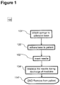
Referring now to the drawings, FIG. 1 illustrates a method of positioning and/or stabilizing a hypodermic needle in accordance with an embodiment 100 of the present invention. In the method an adhesive base is used to retain the skin and/or hypodermic tissue of a patient in a predicable geometry. A syringe retainer holds a syringe in a predetermined position with respect to the base such that a needle mounted to the syringe penetrates the skin to reach a desired tissue. A medicament may optionally be discharged to the desired tissue. The syringe and/or needle may optionally be held in place for an extended period, for example, for a long injection ranging between 30 seconds and 500 seconds. Optionally, an injection could include a large dose for example between 0.5 and 5 ml.
In some embodiments a syringe may be attached 101 to an adhesive base. The attachment may have fixed position and/or the syringe may be movable attached to the base. For example, the attached syringe may move longitudinally between a storage position wherein a needle is shielded by the base and an exposed position wherein a portion of the needle protrudes past the base.
In some embodiments, the base may be adhered 120 to the skin of a patient. Optionally the needle may be attached to the base either before or after adhesion 120 to the skin.
In some embodiments, a needle may be inserted 102 into the skin of the patient. For example, the needle may be inserted 102 by means of a longitudinal movement pushing a portion of the needle into a deployed position point past the base (for example through a hole in the base) into the patent. Optionally, the syringe may be fixedly attached to the base with the needle protruding beyond the adhesive such that placing the adhesive onto the patient also inserts the needle into the patient.
Optionally the device may stabilize 104 in a desired position during discharge of a medicine. When discharge of the medicine finishes, the needle may be removed 114 from the patient and/or the adhesive base may be peeled and/or pivoted from the skin. For example, the entire device may be twisted such that one side of the adhesive is lifted and/or pivoted and/or peeled from the skin while the far edge of the base of the injector remains in contact with the skin and serves as a fulcrum.
2 Method of Injecting a Drug
Referring now to the drawings, FIG. 2 illustrates a method of injecting a drug in accordance with an embodiment 200 of the present invention. In the exemplary method, a needle is optionally held stable while a drug is dispensed to a patient (dispensing a drug may include discharging a drug from the injector).
In exemplary embodiment 200 a user (for example a patient and/or a medical aid in home care) may be supplied 215 with an autoinjeetor ready to administer a medicine.
The user may optionally remove 216 a safety cover from the injector. Removing 216 the cover may optionally include removing a sterile cover from a needle. Removing 216 the cover may optionally automatically peel 218 an adhesive protector from an adhesive. For example, the adhesive may be supplied to stabilize the injector on the skin of a patient during injection. The injector may optionally be fastened 220 to a patient (who may be the user). In some embodiments a user may hold the injector to the skin of a patient; the fastening 220 may stabilize the injector for example from shifts and/or movements of the patient and/or the user.
In some embodiments, the user may set off an activation mechanism. The activation mechanism may for example insert 202 the needle into the patient, for example by extending the needle outward. For example, a syringe may be moveably attached to the base. A syringe may optionally be rigidly attached to the syringe. For example the syringe may slide linearly along its axis. Sliding the syringe towards the base may cause the needle rigidly to protrude beyond the base. For example, part of the needle may pass through a hole in the base and pierce the skin of a patient. The adhesive of the base may hold the skin of the patient steady while the needle pierces the skin. The combination of an adhesive holding the skin and moving the needle to a predetermined position past the base may facilitate the inserting 202 of the needle into the skin to the desired depth.
The needle may optionally be locked in the extended position. Optionally, the needle may be biased to a protected position (for example to retract into a housing of the injector). Alternatively or additionally, the needle may be biased to the unshielded position. Alternatively or additionally, the autoinjector may be supplied with the needle in an extended mode and/or protected by a cover.
At a point during the injection process, an optional manual retraction 224 mechanism may be used to place the injector in a safeguarded mode. For example, when the user decides to abort 222 a-f at a point in the process (for example when he detects some sort of malfunction and/or feels a negative reaction to the medicine) the user may manually retract 224 the needle. Optionally there may be an indicator to indicate 212 whether the needle was automatically retracted 210 and/or whether needle was manually retracted 224. Alternatively or additionally there may be an indicator whether a full dose was administered and/or how much medicine was administered.
Once the needle is inserted into the patient, the injector may optionally begin discharging 204 medicine. For example the medicine may be injected through the needle into the patient. Optionally, discharge may continue until a full dose of the medicine is administered.
In some embodiments, after administration of a full dose of the medicine, there may be a change 206 in resistance to further discharging. For example in a syringe based injector, a plunger may reach the end of the syringe and cease to move increasing resistance. Alternatively or additionally, after discharging the entire dose a transmission may be disconnected (for example a threaded element may pass the end of its threading) reducing resistance. Alternatively or additionally, the change 206 in resistance may result from another cause for example increased resistance due to a full or partial occlusion of a fluid pathway and/or jamming of a mechanical component (for example cross threading of a screw). The change of resistance may optionally be sensed 208 triggering retracting 210 of the needle.
In some embodiments, the needle may be locked in an unshielded state by a force sensitive lock. When the lock senses 208 the change 206 in resistance, it may release 209 the needle which may be retracted 210 to a shielded position.
In some embodiments, a flag may be supplied (for example a LED and/or a changing color indicator) to indicate 212 to the user that the needle has been retracted 210 and/or that the injector can safely be removed 214 from the patient and/or that a fastener has been released. For example, if the injector is adhered to the patient, it may be peeled off and/or a fastener may be released.
3 States of an Autoinjector
FIG. 3 is a state diagram of an autoinjector in accordance with an embodiment of the present invention. In general, may he supplied in an unattached 337 state. An unattached 337 autoinjector may have a secured 331 state. For example in the secured 331 state the injector may be safe to handle and/or transport. Optionally the injector may have an enabled 332 state. For example, in the enabled 332 state, the injector may be unstable and/or easily activated. For example, an injector may be switched from the secured 331 state to the enabled 332 state by removing a needle protector and/or an adhesive cover.
Once activated the injector may optionally be fastened to a patient. In the fastened 338 state the injected may optionally be activated. For example, while the injector is in the active 333 state, a needle may project from the injector. In some embodiments the injector may he hazardous to handle in the enabled 332 and/or active 333 state.
In some embodiments, after use (optionally whether or not administration of the full dose was successful) the user may want to remove and/or dispose of the autoinjector. In some embodiments, it may be difficult and/or dangerous to remove an injector in the enabled and/or active state. For example, when an injector is fastened to a patient by an adhesive, it may be difficult to remove the needle by pulling the injector away from the skin. Optionally, first a needle may be retracted from the skin into the injector. Subsequently the adhesive may be removal by pivoting and/or pulling and/or peeling from the skin. In some embodiments, the injector may automatically be safeguarded 335 for example by retraction of a needle upon completion of injection. Alternatively or additionally, the user may have the option to manually secure the injector into a safeguarded 336 state. For example, the optionally of manually needle retraction may avoid the situation where a patient may not be able to properly remove the injector due to a malfunction that leaves the injector fastened to the skin with the needle inserted into the patient. During and/or after safeguarding 335, 336 the injector may be removed from the patient.
Optionally, the injector may have a final released state 339, for example wherein the needle is retracted back into the injector and/or the needle tip is shielded and/or the injector has been unfastened from the patient. Optionally one or more indicators may be supplied to indicate the state of the injector and/or the quantity of medicine discharged. Once released, the injector may he in final 314 state (protected from hazards and/or ready for disposal, for example in a municipal waste).
4 Fastening Via Clasping
FIGS. 4A-C are schematic illustrations of a drug delivery device including a needle stabilizing mechanism that clasps the skin of a patient in accordance with an exemplary embodiment 400 of the present invention. In exemplary embodiment 400, a needle 460 is biased to a retracted state for example by a spring 462 (see for example FIG. 4A). In the retracted state, an optional clamp 443 may be biased in an open state.
During injection (for example as illustrated in FIG. 4B) needle 460 is optionally held in an extended state by a driver 444 and/or a medicine container 446. In the extended state, clamp 443 may close onto the skin of a patient holding the injector steady. For example needle 460 may be in fluid communication with medicine container 446.
In some embodiments, at the end of injection driver 444 may retract and/or release medicine container 446 and/or the needle 460. For example driver 444 may be unlocked. Once unlocked, driver 444 may optionally revert to a retracted state and/or clamp 443 may optionally be released and/or needle 460 may optionally retract back into the housing (for example as illustrated in FIG. 4D).
In some embodiments locking mechanism may include for example interference elements 452 a,b and/or a locking pin 456 to retain driver 444 in a retracted and/or extended position until a force is applied. For example pin 456 may he rigidly connected to driver 444. In order to move driver 444 from the retracted position (for example as illustrated in FIGS. 4A and 4C) to the extended position (for example as illustrated in FIG. 4B) or back, a force may be applied to push pin 456 past interference elements 452 a,b.
FIG. 4A illustrates exemplary embodiment 400 in an enabled state prior to activation. For example, in the enabled state an optional safety cover and/or a sterile cover may and/or an adhesive protector may have been removed from the injector. In the enabled state a needle 460 is shielded by an activation zone on a base 442 of a housing 440. Needle 460 is safeguarded by a retraction assembly including for example a spring 462 biasing the needle into housing 440 and a needle locking mechanism 458 and a driver 444 which hold needle 460 and its supporting medicine container 446 inside housing 440.
FIG. 4B illustrates exemplary embodiment 400 in an activated state, for example right before and/or at the beginning of discharge of a medication. For example, embodiment 400 is activated by pushing driver 444 with a sufficient force 464 a. Pushing driver 444 optionally pushes needle 460, medicine container 446, and/or clamp 443 from the retracted position (illustrated in FIG. 4A) to the extended position (illustrated in FIG. 4B). Movement may, for example, be along the primary longitudinal axis 477 of medicine container 446. Optionally, needle 460 is shown coaxial to medicine container 446. Alternatively or additional a needle may be mounted off center of a syringe. As clamp 443 moves from the retracted to the extended position, it closes, grasping a skin 466 of the patient.
In some embodiment, once activated, driver 444 may apply a force on plunger rod 450 and/or plunger 448 to discharge medicine. Optionally driver 444 may be configured to drive discharge of the medicine over a relatively long period of time, for example between 30 to 120 seconds and/or between 120 to 600 seconds.
FIG. 4C illustrates exemplary embodiment 400 at the end of discharge of a medicament. Plunger 448 has optionally reached the end of its path. For example, a locking mechanism 458 has been released. Unlocking locking mechanism 458 may optionally trigger releasing clamp 443 and/or safeguarding needle 460.
5 Adhesive Syringe Stabilizer
FIG. 5 illustrates a drug delivery device including an adhesive syringe stabilizer 500 in accordance with an embodiment of the current invention. Syringe stabilizer 500 includes a base 542 adhering to a skin of a patient. A syringe 546 is attached to base 542 by means of a housing 540. Syringe 546 is rigidly connected to a needle 560 which protrudes from syringe 546 past base 542 into a skin 566 of a patient. In operation, needle 560 may be in fluid communication with syringe 546 and/or the patient. Needle 560 is shown in embodiment 500 mounted coaxially to syringe 546 (along the principal longitudinal axis 577 of syringe 546). Optionally, needle 560 may be mounted to the syringe off center. In the present application, the term principle longitudinal axis of a drug container may be used to refer to the longest axis of symmetry of the drug container.
In some embodiments, an adhesive 578 may be attached to a distal surface of a base 542. A housing 540 attached to a proximal side of base 542 may optionally hold syringe 546 with a needle 560 protruding from syringe 546 across base 542 (for example through a hole in base 542).
In some embodiments, syringe 546 may be attached to base 542 prior to adhering base 542 to a patient. The entire assembly may be attached to the patent (piercing the skin 566 with needle 560 and inserting needle 560 into the skin until adhesive 578 contacts skin 566).
In some embodiments, syringe 546 may be movably attached to housing 540. For example, syringe 540 may slide longitudinally along housing 540. Optionally, syringe 546 may be attached to housing 540 with needle 560 held proximal to base 542. Then the distal surface of base 542 may be adhered to skin 566. Subsequently, syringe 546 and needle 560 may be slide longitudinally in the distal direction 579 until needle 560 protrudes through base 542 into skin 566. Once needle 560 has been inserted into skin 566 adhesive 578 may assist a user to steady syringe 546 as he discharges medicine into the patient (for example by pushing on a plunger).
In some embodiments, base 542 may first be attached to the patient. Then a user may hold syringe 546 in his hand and insert needle 560 through a hole in base 542 into the skin of the patent, A possible advantage of inserting needle 560 into skin 566 after attaching base 542 to skin 566 is that adhesive 578 may inhibit deformation of skin 566 during needle insertion. This may make it easier to control the precise depth of insertion. After needle 560 has been inserted syringe 546 may be attached to housing 540. Adhesive 578 may assist a user to steady syringe 546 as he discharges medicine into the patient (for example by pushing on a plunger).
6 Detailed Illustration of States of an Injector
FIGS. 6A-D include detailed cross sectional side views illustrating four states of an autoinjector drug delivery device in accordance with an embodiment of the present invention. In some embodiments, an injector 600 is an automated self injection device. For example the self injecting device may in some ways be similar to a pen injector. Optionally injector 600 may be loaded with a standard type syringe 646 and/or hypodermic needle 660. For example, needle 660 may be rigidly connected and/or project from a distal end of syringe 646. Needle 660 may be coaxial with syringe 646. Alternatively or additionally the axis of needle 660 may be parallel to the primary longitudinal axis 677 of syringe 646 but offset therefrom. Syringe may be loaded into injector 600 with needle 660 in a sterile state and/or covered by a sterile cover.
In some embodiments, an injector may include for example an adhesive 678 base 642. For example, adhesive 678 base 642 may assist a user to hold injector 600 steady on the skin of a patient for an extended period. For example, injector 600 may be used to give injections of volume ranging between 0.5 and 3.0 ml over a time period ranging between 30 sec to 180 sec.
In some embodiments Injector 600 may include a transmission. For example, the transmission may include a rotary screw converting rotational motion of a motor 676 to linear motion for sliding a plunger to discharge a drug and/or for retracting a needle. Alternatively or additionally, in some embodiments, linear motion of the transmission may also be used to insert a needle. For example, in injector 600, the transmission includes for example an annular snap resistance element 652 paired to an annular driver support 656. When a linear stress increases past a threshold, the annular snap gives way and a needle 660 may optionally be retracted to a protected location.
FIG. 6A is a schematic cross sectional side view illustrating injector 600 in an enabled state (ready for activation). For example, in the enabled state an optional safety cover and/or a sterile cover may and/or an adhesive protector may have been removed from the injector. In the enabled state needle 660 is in a protected location, created by a shield 641 which extends the distal end of a housing 640 of the injector. Needle 660 and/or shield 641 may optionally be retained in position, for example by a snap and/or held in position by a biasing device, for example a spring.
In some embodiments, needle 660 may optionally be supported by a syringe 646; which is in turn supported for example by a cylindrical outer sleeve 668. Outer sleeve 668 may optionally be supported by an annular support 656 resting on an annular snap resistance element 652. For example annular snap resistance element 652 may extend radially outward from a cylindrical inner sleeve 667. Optionally, inner sleeve 667 and/or outer sleeve 668 and/or a driver 644 may be operationally linked to a coupling 684 (for example including a gear) such that rotating coupling 684 rotates one or more of inner sleeve 667 and/or outer sleeve 668 and/or a driver 644.
In some embodiments, syringe 646 position sensor, for example a motor switch 682 may be located in shield 641. In the enabled state (before activation), switch 682 is optionally switched off.
In injector 600, syringe 646 is held to outer housing 640 by a socket 661. Socket 661 allows syringe 646 to slide axially with respect to housing 640 but not to move laterally. In injector 600, coupling 684 is held rotatably fixed to housing 640 by bearing 659 in a hub 665.
FIG. 6B is a schematic cross sectional side view illustrating injector 600 immediately after activation. For example, to activate the injector, a user may place the distal end of the injector (including for example an adhesive 678 and/or an activation zone on base 642) against the skin 666 of a patient and/or push 664 on the proximal end of the injector until shield 641 collapses into housing 640 in a direction parallel to the longitudinal axis of needle 660. Collapse of shield 641 may optionally unshield needle 660 tip which may for example be pushed into the skin 666 of the patient. For example, in operation, needle 660 may protrude from injector 600 into a patient. Optionally, in operation, needle 660 may be in fluid communication with syringe 646 and/or the patient. For example needle 660 may supply a fluid pathway for discharging medicine directly from syringe 646 through needle 660 into the patient.
In some embodiments, upon collapse of shield 641 switch 682 senses movement of syringe 646 to the active position and/or activates motor 676. For example in injector 600 switch 682 is depressed by being pushed against syringe 646. Depressing switch 682 may activate motor 676 to power a transmission and/or linear movement of a plunger 648 for discharging a drug. For example, in injector 600 motor 676 turns a coupling 684. Coupling 684 may include for example a gear. Coupling 684 may optionally rotate inner sleeve 667 and/or driver 644. In exemplary injector 600, driver 644 includes teeth and/or threads which engage a screw thread 653 on a plunger rod 650. Rotating driver 644 may optionally drive plunger rod 650 and/or plunger 648 in the distal direction, discharging the medicine. Optionally, plunger 648 continues to move distally until it is stopped by for example a blockage in the fluid path (preventing further discharge) and/or until plunger 648 reaches the distal end of syringe 646. Optionally, when needle 660 is in the extended position, a flange 647 of syringe 646 seats against a bracket 673, which holds syringe 646 and/or prevents further longitudinal movement.
FIG. 6C is a schematic cross sectional side view illustrating injector 600 at the end of discharge of the payload. For example plunger 648 has discharged all of the medicine out of syringe 646 and/or has reached the distal end of syringe 646. Optionally, further rotation of driver 644 increases the stress pushing driver 644 proximally. Interference element 652 may serve as stress sensor. For example, motor 676 may supply enough torque to create a force which overcomes interference element 652.
In some embodiments, once interference element 652 is overcome a course inner threading 655 in sleeve 667 rotates with respect to a course outer thread 651 of driver 644 drawing driver 644 and/or plunger 648 and/or syringe 646 and/or needle 660 proximally into a retracted state. For example, the course thread 651 has an opposite threading from the threading 653 between driver 644 and plunger rod 650. The same direction of rotation that drives plunger 648 distally before overcoming interference element 652 also draws back plunger 648 and/or syringe 646 and/or needle 660 proximally after overcoming interference element 652. Optionally needle 660 is retracted into a protected location inside housing 640 for example as illustrated in FIG. 6D. Alternatively or additionally, course thread 651 may have an the same direction of threading as threading 653 between driver 644 and plunger rod 650 and optionally rotation may be reversed to retract needle 660.
FIG. 6D is a schematic cross sectional side view illustrating injector 600 in a safe state after finishing injection. Needle 660 point has optionally been retracted into a protected location within housing 640. Syringe 646 has optionally been retracted. In exemplary injector 600, switch 682 senses that syringe 646 is retracted, as syringe 646 no longer depresses switch 682. Switch 682 may be biased off and/or raising syringe 646 may shut off motor 676.
In some embodiments one or more windows may be supplied. A user may be able to determine a status of the device by viewing for the windows. For example in FIG. 6D, injector 600 has been supplied with two windows 690 a,b. For example window 690 a is located such that during injection, the user views inner sleeve 667 through window 690 a. When outer sleeve 668 has been retracted, it may optionally slide over inner sleeve 667. After outer sleeve 668 has been retracted, the user views outer sleeve 668 through window 690 a. Optionally window 690 a may serve as an indicator whether it is safe to remove the injector. For example, outer sleeve 668 may be colored green and/or driver 644 and/or inner sleeve 667 may be colored red. For example, as long as the user sees red in window 690 a needle 660 tip has not been retracted and/or it is unsafe to remove the injector from the patient's skin; and/or when the user views green through window 690 a needle 660 has been retracted and/or discharge has ceased and/or it is safe to remove the injector from the skin of the patient. Optionally, window 690 b may be used to indicate whether an entire payload of medicine has been administered. For example, syringe 646 may be made of a transparent material. For example, during injection, the user can see the medicine through window 690 b; after syringe 646 is retracted if the payload has been fully discharged then the user will view plunger 648 through window 690 b. Optionally, if the user sees plunger 648 through both window 690 b and outer sleeve 668 through window 690 a then the user can ascertain that it is safe to remove the injector and/or that the drug was fully discharged.
In injector 600, for example, after retraction of the needle the device may be twisted such that one side of the adhesive is lifted and/or pivoted and/or peeled (as illustrated by arrow 683 in FIG. 6D) from the skin while the far edge of the base of the injector remains in contact with the skin and serves as a fulcrum.
FIGS. 6E and 6F illustrate an external view and cut away view respectively of a transmission for driving discharge and retracting a needle in accordance with exemplary embodiment (for example injector 600) of the current invention. Injector 600 may optionally be designed such that, under sufficient linear stress, support 656 of external sleeve 668 deforms and/or opens to pass over resistance element 652. Optionally, coupling 684 and/or inner sleeve 667 may be formed of one or more pieces of molded plastic. Optionally outer sleeve 668 and/or driver 644 may be formed of one or more pieces of molded plastic.
FIG. 6F, illustrates details of a rotary needle retractor in accordance with an embodiment of the current invention. FIG. 6F illustrates driver 644 before needle retraction (for example in a secured state, an enabled state and/or an active state). In the exemplary embodiment, driver 644 is engaged by a set of fine screw threads 653 to rod 650. In the exemplary embodiment, driver 644 is engaged by a set of course screw threads 651, 655 to inner sleeve 667. Optionally, course screw threads 651, 655 are threaded in an opposite sense from fine screw threads 653.
In the exemplary embodiment, prior to needle retraction, sleeve 667, 668 and driver 644 are prevented from sliding longitudinally with respect one another. While sleeves 667, 668 and driver 644 are prevented from relative longitudinal movement, threads 651 and 655 prevent inner sleeve 667 and driver 644 from rotating with respect to one another.
In some embodiments, motor 676 drives coupling 684 to rotate inner sleeve 667. Optionally, before needle retraction, rotating inner sleeve 667 rotates driver 644. The sense of screw threads 653 and the rotating direction of motor 676 are optionally chosen such that rotating driver 644 relative to rod 650 pushes rod 650 and/or plunger 648 distally, optionally discharging a drug.
When plunger 648 has reached the distal end of syringe 646, rod 650 is prevent from further distal movement. Torque applied to driver 644 produces a strong proximal stress on driver 644 and/or outer sleeve 668. The strong proximal stress overcomes and/or releases interference element 652. Once interference element 652, is released outer sleeve 668 and/or driver 644 can move longitudinally with respect to inner sleeve 667. Further rotation of inner sleeve 667 rotates sleeve 667 with respect to driver 644. The sense of screw threads 655 and 651 and the rotating direction of motor 676 are optionally chosen such rotating driver 644 relative to sleeve 667 draws driver 644 and/or rod 650 and/or plunger 648 and/or syringe 646 and/or needle 660 proximally, optionally retracting needle 660. Optionally the pitch of screw threads 651, 653 and/or 655 can be tuned to achieve a desired rate of medicine discharge and/or needle retraction for a given rotation rate of the motor. In some embodiments, as rod 650 and/or plunger 648 are drawn proximally, friction between plunger 648 and syringe 646 draws syringe 646 and/or needle 660 proximally. Alternatively or additionally, outer sleeve 668 may be attached to syringe 646. Drawing back on driver 644 may draw outer sleeve 668 and syringe 646 back with it. In some embodiments additional threaded elements may be added to produce a multi-part telescoping assembly for extending plunger 648 to discharge medicine and/or for retracting needle 660. In some embodiments some or all of rod 650, inner sleeve 667, and/or outer sleeve 668 and/or coupling 684 may be formed of molded plastic and or other materials.
7 Stabilized Pen Injector
FIGS. 7A-H illustrate a drug delivery device including a stabilized injector 700 in accordance with some embodiments of the present invention. Exemplary injector 700 is an automated injection device in some ways similar to a pen injector. Optionally injector 700 may be loaded with a standard type syringe 646 and/or hypodermic needle 660. Optionally syringe 646 may be supplied loaded with medicine and/or covered with a sterile needle cover 791. Syringe 646 may be loaded into injector 700 with in a sterile state with needle cover 791 in place. Injector 700 may include for example an adhesive 678 base 642. In some embodiments, adhesive 678 base 642 may assist a user to hold injector 700 steady on the skin of a patient for an extended period. For example, injector 700 may be used to give injections of volume ranging between 0.5 and 3.0 ml over a time period ranging between 30 sec to 180 sec.
FIG. 7A illustrates an exploded view of injector 700. Some components of the exemplary embodiment of injector 700 which are similar to corresponding parts of the exemplary embodiment of injector 600 are marked with the same number as the corresponding parts of the exemplary embodiment of injector 600.
In the exemplary embodiment of injector 700 a power supply (for example batteries 770) may optionally supply power to gear motor 676. FIGS. 7A,B illustrate flange 647 of syringe 646. Optionally flange 647 has at least one non-rounded edge which may be held inside an autoinjector (for example autoinjectors 400, 600 and/or 700) preventing rotation of syringe 646. Outer housing 740 and/or shield 741 of injector 700 are similar to outer shell 640 and/or shield 641 of injector 600.
Some embodiments of a stabilized autoinjector (for example as illustrated in injector 700 but optionally included in injectors 600 and/or embodiments 400 and/or 200 and/or 100) may include a safety cover and/or an adhesive protector and/or a handle. Details of an exemplary embodiment of an adhesive protector 789 and/or a handle 794 and/or a needle cover remover, for example a safety cover 792 are illustrated in FIGS. 7C-H.
FIG. 7B illustrates an exemplary transmission including a retraction mechanism 758. Retraction mechanism 758 is optionally activated by a combination of torque and linear stress. For example retraction mechanism 758 is optionally activated may when plunger 648 is blocked for example when it reaches the end of injection (for example as described in regards to FIGS. 6A-D and/or due to an occlusion of needle 660).
In some embodiments, during drug discharge a motor (for example motor 676) rotates coupling 684 in the direction of arrow 783. Coupling 684 may optionally be rigidly connected to and/or integrally molded with inner sleeve 768. Rotating coupling 684 may also rotate inner sleeve 768. A pin 756 protrudes from driver 744 into a nearly lateral slot 754 a in sleeve 768. While pin 756 is in slot 754 a, driver 744 is prevented from moving longitudinally with respect to inner sleeve 768. In some embodiments syringe 646 is supported (from moving proximally) by driver 744.
In some embodiments, when there is a strong linear force on driver 744 in the proximal direction and/or there is a strong torque on sleeve 768 in the direction of arrow 783, arm 757 is deflected upward and pin 756 slides past an interference element 752 into a longitudinal slot 754 b. In slot 754 b pin 756 may slide longitudinally (in the proximal direction). A geometry of pin 756 and/or interference element 752 may be chosen to achieve a desired resistance to movement. For example, pin 756 and/or interference element 752 may have a squared side, a flat side, a rounded side etc.
In some embodiments, a spring (for example spring 762) biases syringe 646 in the proximal direction. For example spring 762 may apply a proximal force to flange 647. Optionally another biasing element may be used in place of spring 762. For example, a biasing element may include a stretched element (for example a rubber band and/or a twisted elements and/or a deflected plastic element).
Optionally when pin 756 enters longitudinal slot 754 b, spring 762 pushes syringe 646 and/or outer sleeve 767 and/or needle 660 and/or driver 744 and/or pin 756 proximally, retracting needle 660. Optionally, needle 660 may he held in the retracted position by spring 762. Alternatively or additionally a locking mechanism may be included to lock needle 660 in the retracted position, for example, a one way catch and/or an interference element may lock against syringe 646 as it is retracted and/or against pin 756 in slot 754 b. Optionally, in injector 700 driver 744 includes two molded plastic telescoping pieces. One piece is optionally integrally molded with outer sleeve 767. Optionally, sleeve 767 and/or driver 744 may be made as a single piece and/or multiple parts. They may be formed of plastic and/or another material and/or they may be molded and/or formed by another process.
FIGS. 7C and 7D illustrate an exemplary method of folding adhesive protector 789. For example, adhesive protector may include three folded portions 785 a, 785 b, and 785 c. For example, adhesive protector may include three holes 787 a, 787 b, and 787 c. When folded, the side portions 785 b,c may fold over the center portion 785 a. Side holes 787 c,b may line up with center hole 787 a. Alternatively or additionally, an adhesive protector may have only one fold and/or one side portion and/or peeling may be from one side only.
In some embodiments, portion 785 a will be adhered to base 642 with the needle opening accessible through holes 787 a-c. A safety cover (for example cover 792) may protrude through holes 787 a-c. The safety cover may optionally be connected to portions 785 b,c. The safety cover may pass freely through hole 787 a and/or not be connected to portion 785 a of adhesive protector 789.
FIGS. 7E-H illustrate removal of an exemplary safety cover 792, needle cover 791 and/or adhesive protector 789. For example, while safety cover 792 is mounted to needle cover 791, safety cover may prevent deployment and/or activation of the injector. For example, safety cover 792 and handle 794 may supply a convenient means of removing needle cover 791 and/or adhesive protector 789.
FIG. 7E illustrates injector 700 in a safe state for storage and/or transport. Needle cover 791, safety cover 792 and adhesive protector 789 are in place. Adhesive protector 789 is folded for example as illustrated in FIGS. 7C,D. Needle cover 791 (not seen in the drawing) may optionally preserve the sterility of needle 660. Safety cover 792 surrounds and grasps needle cover 791. Safety cover 792 may prevent inadvertent activation of the injector and/or protect users from a needle stick hazard.
FIG. 7F illustrates the beginning of removal of safety cover 792. A user pulls handle 794 away from needle 660. Handle 794 pulls needle cover 791 out the needle hole and/or needle aperture of injector 700 and through hole 787 a. As cover 792 is pulled away from base 642, portions 785 b,c of adhesive protector unfold while portion 785 a remains adhered to base 642.
FIG. 7G illustrates that as safety cover is pulled further away from base 742 portions 785 b,c of adhesive protector 789 pull and/or pivot and/or peel portion 785 a away from base 742.
FIG. 7H illustrates cover 792 arid protector 789 fully removed from injector 700, such that injector 700 is enabled and/or ready to adhere to a patient and/or ready for activation.
FIG. 7I illustrates exemplary embodiment 71 assembled and/or in an enabled state before insertion of needle 660 into a patient. FIG. 7I illustrates various optional details and/or supporting structures for syringe 646 and/or plunger.
In injector 700, syringe 646 is held to outer housing 740 by a socket 761. Socket 761 allows syringe 646 to slide axially with respect to housing 740 but not to move laterally. In injector 700, coupling 684 is held rotatably fixed to housing 740 by bearing 759 in a hub 765.
FIG. 7J illustrates exemplary injector 700 in an active state. For example when the injector is in the enabled state, a user may place adhesive against the skin of a patient and push downward (distally) on housing 740. Housing 740 and its contents (for example syringe 646, coupling 684, locking assembly 758 etc.) along with needle 660 are all pushed distally along the axis of needle 660. As needle 660 moves distally, the needle tip passes through a hole in shield 741. For example, in operation, needle 660 may protrude from injector 600 into a patient. Optionally, in operation, needle 660 may be in fluid communication with syringe 646 and/or the patient. For example needle 660 may supply a fluid pathway for discharging medicine directly from syringe 646 through needle 660 into the patient.
In some embodiments, when needle 660 is in the extended position, the front end of syringe 646 seats into a bracket 773. Bracket 773 may optionally hold syringe 646 steady and/or prevents further longitudinal movement and/or prevent lateral movement with respect to housing 740.
FIG. 7K illustrates injector 700 after needle retraction. Optionally driver 644 includes a telescopic assembly, which is shown in an extended state in FIG. 7K. Optionally, after retraction of needle 660, the entire device may be twisted to pivot and/or peel adhesive 678 from the skin.
Various aspects or features illustrated herein with respect to a particular embodiment may be combined with other embodiments. For example, needle 460 and 560 of embodiment 400 and 500 are shown mounted at an angle to base 442 or 542. Alternatively or additionally they may be perpendicular to the base. For example, needles 660 of embodiments 600 and 700 are shown perpendicular to base 642. Alternatively or additionally they may be at an angle to the base. Needle covers and/or protective covers illustrated in one embodiment may be used with another embodiment. Retraction mechanisms illustrated in one embodiment may be used with another embodiment. A clip, an interference element, a catch and/or another locking mechanism may hold an injector in one or another state. For example an interference element may hold a needle in a retracted position and/or in the extended position.
8 Method of Manufacture of a Stabilized Pen Injector
FIG. 8 is a flow chart illustration of a method of manufacture of a stabilized pen injector in accordance with an embodiment of the present invention. In the method a preloaded sterile syringe and needle may optionally be installed into an autoinjector for direct injection into a patient. For example the method of manufacture illustrated in FIG. 8 may optionally be used in manufacturing one, some and/or any of the embodiments of an injector illustrated herein above and/or below.
In some embodiments a syringe is preloaded 805 with a medicine. For example the volume of preloading medicine may range between 0.5 and 1 ml and/or between 1 and 5 ml and/or greater than 5 ml of medicine. Preloading 805 may optionally be performed on standard syringe equipment and using standard filling procedures. Optionally the syringe may be a standard type syringe. For example preloading may be done in an aseptic environment. Optionally, a sterile needle and/or needle cover may be attached before filling the syringe. For example, the syringe may be filled while attached to a sterile needle and/or a sterile needle cover. Alternatively or additionally, the syringe may be attached to a sterile needle and/or a sterile needle cover while being filled and/or after being filled. Sterility of the needle may optionally be protected by a needle cover (for example cover 791).
In some embodiments, the preloaded syringe with the sterile, protected needle may be installed 811 in an autoinjector including an adhesive stabilizer (for example one of the autoinjectors described herein above). Optionally, installing 811 the syringe may include engaging 813 a driver to a power source, for example a battery (for example directly and/or via a motor and/or coupling and/or a transmission) and/or a mechanical power source for example a spring.
In some embodiments, the fluid path of the injector may include the medicine container and/or the needle. For example, in operation, medicine stored in the container may pass directly from the container to the needle and/or from the needle directly to the patient. Optionally, the entire fluid path may be in a complete and/or sterile and/or assembled and/or protected state prior to and/or during filling of the container. For example, a syringe medicine container and/or needle may be filled and sealed under aseptic and/or sterile conditions, for example in an aseptic room. For example the syringe may be sealed by a needle cover and/or a plunger. Optionally, the syringe, with the fluid path in a sealed and/or protected state may be taken from the aseptic filling room and installed into an injector. Optionally, the fluid path may not require sterilization after being removed from the filling room and/or after installation into the injector.
In some embodiments, a cover remover (for example safety cover 792) may be attached 817 to the needle cover through a hole in the adhesive. In some embodiments, the hole in the adhesive may be surrounded by the adhesive. Alternatively or additionally, the hole may be surrounded by the adhesive on two sides and/or on three sides. For example, the adhesive may be made of two pieces, one piece on one side of the hole and another piece on another side of the hole. The autoinjector may then be ready to be supplied 819 to a user. For example the user may use the cover remover to remove the needle cover and/or to enable the injector.
9 Stabilized Injector Dimensions
FIG. 9 illustrates an external view of a stabilized injector drug delivery device in accordance with an embodiment of the current invention. In FIG. 9 exemplary dimensions are shown to help understand the relationship between the size and weight of the injector and the strength and geometry of the adhesive. For example, any, some and/or all of the features and/or dimensions described herein below may apply to any, some and/or all of the embodiments described herein above.
In some embodiments, the height of an autoinjector (perpendicular to the adhesive layer) may be greater than then width of the adhesive layer (for example the height may be greater than the greatest length between any two points on the adhesive layer). For example, the distance 929 a from the longitudinal center of mass 949 a of the injector and the adhesive surface 678 may range for example between 50±10 mm and/or the longitudinal center of mass may range for example between 60 and 80 mm from the adhesive. In some embodiments, the longitudinal center of mass may be greater than for example between 80 mm from the adhesive. The distance 929 b between the lateral center of mass 949 b of the injector and the center of adhesion 949 c on the base of the apparatus (when the weighted center of force on the adhesive when the injector is twisted off the skin in the direction of the arrow 983 in FIG. 9) may range, for example between 12.5±4 mm. The width 929 c of base 642 may range, for example, between 60±15 mm. There may optionally be a semi-stiff skirt 945 extending beyond the edge of base 642 for example between 0 to 2 mm and/or embodiments skirt 945 may extend for example between 4 to 10 mm beyond base 642. In some embodiments, the width of skirt 945 may vary at various points around base 645. (For example the skirt may be made of plastic, for example Polyethylene terephthalate (PET) and/or Polycarbonate and/or ABS. The thickness may range for example between 0.1 to 0.8 mm.). The thickness of adhesive layer 678 may range between 0.1 and 1 mm. An injector may weigh for example 50±20 g. Then the resting torque adhesive when the injector is adhered to a vertical object will be approximately 50 mm×50 g=2500 g×mm. The strength of adhesion necessary to hold the injector to the patient will be approximately 2500 g×mm/12.5 mm=200 g. In some embodiments, movements of the user may place a considerably stress on the injector than the static stress. For example an adhesive may be provided to give a total adhesive strength ranging between 500 to 1500 g.
In some embodiments, the adhesive will be less strong and/or maybe easier to remove. For example the strength of the adhesive may be less than 500 g (for example the user may have to hold the injector with his hand to prevent it from falling, especially when the user is moving). Alternatively or additionally the adhesive may not include semi-stiff skirt 945.
10 Microswitch Activator for an Autoinjector
FIGS. 10A-D is are cutaway illustrations of an exemplary embodiment of an autoinjector 1000 drug delivery device including a motor switch located in the main body of the injector in accordance with some embodiments of the current invention. Optionally the motor switch remains stationary with respect to the housing of the autoinjector, for example housing 640, and/or with respect to and/or a motor and/or a power source, for example batteries 1070. When an activator of the injector is triggered (for example by collapsing a shield 1041), movement of the activator may activate the switch. When the needle 660 is retracted and/or shielded (for example after injection), the switch is optionally returned to the inactivated state. Keeping a switch stationary with respect to a motor and/or power source may simplify assembly of the auto injector.
FIG. 10A illustrates injector 1000, prior to activation in accordance with an embodiment of the current invention. Optionally many structures are the same as other embodiments listed herein above or below, for example, injector 1000 may include the advancement and/or retraction mechanism of injector 600. Optionally, prior to activation, a syringe position sensor, switch 1082 senses that shield 1041 is in a deactivated position. When shield 1041 is in a deactivated position, switch 1082 optionally deactivates the motor of injector 1000.
FIG. 10B illustrates injector 1000, immediately after activation in accordance with an embodiment of the current invention. In some embodiments, an injector may be activated by collapsing a needle shield 1041. Collapsing shield 1041 optionally exposes needle 660. Optionally the syringe position sensor (switch 1082) senses the new position of shield 1041. For example, shield 1041 pushes an element 1052 against a side of a syringe and/or pushes an extension 1025 of shield 1041 into switch 1082 and/or activates switch 1082 and/or activates a motor (for example similar to motor 676 of injector 600).
FIG. 10C illustrates injector 1000, immediately at the end of injection in accordance with an embodiment of the current invention. Optionally for as long as shield 1041 remains in a collapsed state and/or needle 660 remains in an extended state (protruding from the injector), extension 1025 continues to hold switch 1082 in an activated state and/or a motor continues to drive plunger 648. Optionally, when plunger 648 reaches the end of syringe 646 a retraction mechanism (for example retraction mechanism 758) retracts syringe 646 and/or needle 660 to a retracted state (as illustrated for example in FIG. 10D).
FIG. 10D illustrates injector 1000 in a retracted state in accordance with an embodiment of the current invention. Optionally, when needle 660 and/or syringe 646 is retracted, element 1052 is released and/or extension 1025 moves away from switch 1082 and/or switch 1082 moves into a deactivated state and/or the motor is switched off.
11 Method of Stabilizing an Autoinjector
FIG. 11 is a flow chart illustration of a method 1100 of adapting an injector for extended use in accordance with an embodiment of the present invention. For example an injector may be attached to a stabilizing adaptor. Stabilization may extend use of the injector to longer injection time and/or higher viscosity medicines and/or colder conditions.
In some embodiments, an injector housing may be supplied 1115. Optionally the housing is attached 1101 to a connector. Optionally, the housing may be attached 1101 to the connector prior to assembly of autoinjector and/or prior to loading the autoinjector with medicine. For example, the autoinjector may be attached to the connector by a drug company and/or by a medical device supplier. Alternatively or additionally the injector housing may be supplied as part of an assembled autoinjector unattached to the connector. For example patient and/or a medical professional and/or a patient aid may attach 1101 the housing to the connector before use.
In some embodiments, a stabilizing adaptor may be fastened 1120 to a patient. Optionally, after attaching 1101 the injector to the adaptor, the entire assembly is fastened 1120 to the patient. For example, a patient and/or a medical professional and/or a patient aid may be supplied with a fully assembled injector and adaptor. For example the patient and/or the medical professional and/or the patient aid may fasten 1120 the assembled injector and adaptor to the patient and perform the injection. Alternatively or additionally, the adaptor may be fastened 1120 to the patient without the injector and then the injector may he attached 1101 to the adaptor while the adaptor is already fastened 1120 to the patient. For example, the adaptor may he fastened 1120 to the patient by a medical professional and/or patient aid and/or in a clinic and/or in a hospital. Later on the injector is optionally attached to the adaptor and/or enabled and/or activated, for example by the patient himself and/or a medical aid for example at home or elsewhere away from medical supervision.
In some embodiments, during discharge of the medicine, the autoinjector may be stabilized 1104 on the injection site of the patient by the adaptor.
In some embodiments, after injection ends, the injector and/or the adaptor may be removed 1114 from the patient. For example, the injector and the adapter may be removed 1114 together. Alternatively or additionally the injector may be disconnected from the adapter and removed from the patient while the adapter remains fastened to the patient, to be used for another injection and/or removed 1114 later.
12 States of an Autoinjector and Extending Adaptor
FIG. 12 is a state diagram of an autoinjector and extending adaptor in accordance with an embodiment of the current invention. An autoinjector may have two or more optional operating states. For example the injector may operate in an autonomous state 1205 and/or in an operationally extended state 1207. Operationally extended state 1207, optionally includes operation of the injector extended to longer times and/or more viscous medicines and/or larger injection volumes. In some embodiments, operational extended state 1207 may include extension of the length of the injector. Alternatively or additionally, operational extended state 1207 may not include extension of the length of the injector. Prior to use the injector may have an unattached 1203 state and/or after use the injector may have a detached 1217 state.
In some embodiments, an injector may operate 1209 in an autonomous state 1205. For example in the autonomous state the autoinjector may inject a medicine without an adaptor. Optionally in the autonomous state 1205 the injector may have a set of controls that are activated by a user in order. In the autonomous state 1205 the injector may inject a medicine in accordance with a prescribed protocol.
In some embodiments, the injector may operate 1215 in an extended state 1207. In extended state 1207, for example, an adaptor may be used to stabilize 1213 the injector on a patient. For example, the stabilized configuration may allow injection for longer periods of time and/or for a more dexterity limited patient. In the extended state 1207, operation 1215 is optionally activated by the same set of controls and/or in accordance with the same protocol as in operation 1209 in the autonomous state 1205. For example, for a higher viscosity medicament (for example a medicament at a lower temperature) using the same controls and protocol, the injector may require a longer time to discharge its payload. For example, extended operation 1215 may be very useful when an injector has been tested and/or approved for operation 1209 in the autonomous state 1205, but under some conditions (for example when the medicine is cold) the injector does not meet certain requirements. For example, the injector requires more than the maximum approved time to discharge its payload. Adding the adaptor optionally makes minimal changes in the user interface and/or operation protocol of the injector, while allowing extended operation 1215. Thus, for example with the adaptor may allow use of the injector in extended operation 1215 under extended conditions with reduced testing and/or approval while taking advantage of previous testing and/or regulatory approval of autonomous operation 1209 under more limited conditions.
13 Block Diagram of an Autoinjector and a Stabilizing Adaptor
FIG. 13 is a block diagram of an autoinjector 1300 and adapter 1327 in accordance with an embodiment of the present invention. Optionally an adaptor 1327 may extend operation of injector 1300. For example, adaptor 1327 may stabilize injector 1300 on a patient allowing for longer injection times than for injector 1300 operating in an autonomous mode.
In some embodiments, adaptor 1327 may include a connector 1341 for attaching the adaptor to the injector and/or a fastener 1342 for fastening to a patient. For example, connector 1341 and fastener 1342 may be a single integrated part (for example molded out of a single piece of plastic). Alternatively or additionally, connector 1341 and fastener 1342 may be formed as two separate parts. Optionally, adapter 1327 including connector 1341 and fastener 1342 are first attached to injector 1300 and the complete assembly fastened to patient 1366 as a unit. Alternatively or additionally, adapter 1327 including connector 1341 and fastener 1342 may be fastened to the patient and injector 1300 stabilized as it is placed onto the patient. Alternatively or additionally, connector 1341 may be attached to the injector and fastener 1342 may be fastened to the patient and/or as injector 1300 is placed on the patient, connector 1341 is mated with fastener 1342 stabilizing the injector. In some embodiments there may be multiple fasteners 1342 and/or connectors 1341.
In some embodiments, connector 1341 may attach to an outer housing of injector 1300. For example, connector 1341 may be attached by a clamp and/or a friction fitting that grasps the walls of injector 1300. For example the injector 1300 may have a patient contact surface on a distal end thereof and connector 1341 may be attached to the side walls of the injector 1300. Alternatively, connector 1341 may attach to injector 1300 via an adhesive. In some embodiments, connector 1341 may be adjustable and/or adapted to attach any of a plurality to different injectors. In some embodiment, connector may be configured to attach to a specific injector. Alternatively or additionally other connection methods like magnetic force or Velcro are possible.
In some embodiments, connector 1341 may mate to fastener 1342 by a friction fitting. Alternatively or additionally connector 1341 may mate to fastener 1342 by a threaded fitting and/or a clamp and/or an interference element and/or a snap. The connection between fastener 1342 and connector 1341 may be reversible and/or may be permanent and/or irreversible (for example using a tooth and ratchet fitting). For example a ratchet and thread fittings may enable process of fixing and linkage. With a magnetic fitting linkage may occur alone. Adhesive, friction and/or Velcro® fittings may include passive actions that user should do properly. With thread, magnet, friction and/or Velcro it may be simple to disengage the device from the adaptor for example for re-use.
14 Adhesive and Ring for Stabilizing an Autoinjector
FIGS. 14A-F illustrate use of a drug delivery device, for example an injector 1400 and a stabilizing adapter 1427 in accordance with an embodiment of the current invention. In an exemplary embodiment, adapter 1427 includes an optional connector 1441 in the form of a ring. Optionally, the distal end of injector 1400 is inserted into a cavity 1411 of adaptor 1427. Optionally, connector 1441 is permanently fixed to a fastener 1442 including a base and an adhesive 1478 for adhering to skin in the vicinity of an injection site 1466 of a patient (for example see FIG. 14C). For example the adhesive may surround the injection site and/or may be in an area within 1 cm of the injection site and/or within 5 cm of the injection site. Connector 1441 is optionally configured to surround and/or limit movement of a distal surface of an outer housing 1440 of injector 1400.
In some embodiments, injector 1400 may be configured for operation in an autonomous mode and/or without adapter 1427 and/or without stabilization. For example, injector 1400 may include for example a pen injector and/or for example one of the many pen injectors known in the art. Control and/or operation protocols of the stabilized injector 1400 in the extended mode (for example with adaptor 1427) may be unchanged over operation in the autonomous mode.
FIG. 14 A is an exploded perspective view of injector 1400 and adapter 1427 in accordance with some embodiments of the current invention. In some embodiments, connector 1441 may limit lateral movement (in the x-y plane parallel to injection site 1466 of the patient) of the distal end of injector 1400. Additionally and/or alternatively, connector 1441 may limit rotational movement of injector 1400. For example, connector may closely surround injector 1400 along its length, preventing rotation around the x and/or y-axis. For example, connector 1441 may attach itself to the side walls of injector 1400 over a length ranging between 0.5 cm and 2.0 cm and/or 2.0 cm to 5.0 cm and/or longer. Optionally, friction between housing 1440 and connector 1441 may prevent rotation of injector 1400 around its main axis (the z-axis). Alternatively or additionally, connector 1441 may limit movement of injector 1400 perpendicular to the injection site of the patient. For example, friction between connector 1441 and housing 1440 may prevent movement of injector 1400 in the axial direction (along the z-axis).
In some embodiments, adaptor 1427 may be fastened to a patient before being attached to injector 1400. For example, a doctor may give a patient an injector 1400 including a medicine to be taken at a certain time after the patient is discharged from the hospital. A member of the hospital staff may fasten fastener 1442 and/or connector 1441 to the patient at a preferred injection location. When the time comes for the injection, the patient optionally inserts the distal end of injector 1400 into connector 1441 and activates injector 1400. Alternatively or additionally a member of the hospital staff may fasten fastener 1442 to the patient at a preferred injection location. When the time comes for the injection, the patient optionally mates connector 1441 to fastener 1442 and/or inserts the distal end of injector 1400 into connector 1441 and/or activates injector 1400. Alternatively or additionally, when the time comes for the injection, the patient may fasten fastener 1442 and connector 1441 to his injection site 1466 at a preferred injection location. The patient optionally then inserts the distal end of injector 1400 into connector 1441 and activates injector 1400. Optionally, connector 1441 may be configured to make it easy for a limited dexterity patient to position injector 1400. For example, the opening to connector 1441 may be beveled, for example the opening of connector 1441 may be beveled, for example like a funnel, to help direct the distal end of injector 1400 to the injection site.
In some embodiments, injector 1400 may be attached to connector 1441 before fastening to the patient. The patient optionally, fastens the entire assembly (injector 1400 and adapter 1427) together to the injection location and/or activates the injector.
In some embodiments cavity 1411 may be cylindrical. The cross section of cavity 1411 optionally has a shape to fit the cross section of the distal end (the end nearest to the patient) of the injector. For example, the cross section of the distal end of the injector and/or of cavity 1411 may be circular and/or elliptical and/or rectangular and/or may have rounded corners. Alternatively or additionally cavity 1411 may be conical and/or pyramidal, for example with a large opening. The large opening may make it easier to insert the injector. The surface of contact between injector 1400 and adaptor 1427 may include, for example, the surface of the inner walls of adapter 1427 which contact, for example, the outer surface of the distal end of injector 1427.
FIG. 14B is a crossectional view of injector 1400 and adapter 1427 prior to positioning on a patient and/or prior to injection in accordance with an embodiment of the current invention. A distal surface 1423 including a skin contact area is illustrated above an injection zone 1466 of the patient.
FIG. 14C is a crossectional view of injector 1400 and adapter 1427 positioned on a patient prior to injection in accordance with an embodiment of the current invention. Optionally injector 1400 includes a needle 1460 and/or a plunger 1448. Optionally, injector 1400 includes a drive mechanism and/or a needle extension/retraction mechanism, for example, similar to embodiment 400 and/or injector 600 and/or 700 above. In some embodiments connector 1441 may attach to the side walls of injector 1400. For example connector 1441 may be attached to a length of the side walls of the injector.
FIG. 14D is a crossectional view of injector 1400 and adapter 1427 positioned on a patient after activation and/or extension of needle 1460 into injection site 1466 and/or during injection as plunger moves downward discharging medicine into the patient in accordance with an embodiment of the current invention.
FIG. 14E is a crossectional view of injector 1400 and adapter 1427 positioned on a patient after injection in accordance with an embodiment of the current invention. Optionally, after injection, plunger 1448 has reached the end of its movement, discharging a full dose of the medicine and/or needle 1460 has retracted.
FIG. 14F illustrates removal of an injector from a stabilizing adapter and/or patient in accordance with an embodiment of the current invention. In the embodiment of FIG. 14F, injector 1400 is optionally removed from injection site 1466 while adapter 1427 optionally remains on injection site 1466. For example, adapter 1427 may be used to stabilize an injector in a subsequent injection. Alternatively or additionally adapter 1427 may be removed from injection site 1466 after removal of injector 1400. Optionally, injector 1400 and/or adaptor 1427 are disposed of and/or reused and/or recycled separately and/or together. Alternatively or additionally, injector 1400 and/or connector 1441 and/or fastener 1442 may be removed from injection site 1466 together. For example, injector 1400 may be rotated to pivot off fastener 1442, for example in a manner similar to that illustrated in FIG. 6D. For example, using injector 1400 to pivot off fastener 1442 may be easier for patients with limited small motor skills that trying to pull and/or pivot and/or peel off fastener 1442 on its own.
15 Friction Fitting for Stabilizing an Autoinjector
FIG. 15 is a cross sectional illustration of injector 1400 and a stabilizing adapter 1527 including a friction fitting 1543 prior to positioning on a patient and/or prior to injection in accordance with an embodiment of the current invention. For example friction fitting 1543 may include a friction coating on the surface of contact between adapter 1527 and injector 1400. For example friction fitting 1543 may be on the inner surface of a cavity 1511 in a connector 1541. For example the fitting may include slanted teeth that increase the friction in one direction. For example it may require less force to insert injector 1400 into adapter 1527 then to remove injector 1400 from adapter 1527. Operation of adapter 1527 may for example be as described with respect to adapter 1427.
16 Adjustable Angled Stabilizing Adaptor
FIG. 16 is a perspective view of injector 1400 and a stabilizing adapter 1627 having an adjustable angle between injection site and the injector in accordance with some embodiments of the current invention. For example the angle during operation of the injector between the skin surface at the injection site and the principle axis of the injector, the principle axis of the drug reservoir and/or the principle axis of the needle may be adjusted between 80 to 100 degrees and/or between 60 and 120 degrees and/or between 30 and 150 degrees.
In some embodiments, the connection between injector 1400 and/or adaptor 1627 and/or fastener 1442 may include a pivot 1675 and/or an axel (for example as illustrated on connector 1641). Optionally a lock may fix the angle of injection. For example a lock may include a ratchet and teeth and/or a clamp.
In some embodiments an angle of the injection may be set prior to distribution of the injector and/or adaptor to a patient. For example, the angle may be set by a staff member at a hospital and/or clinic and/or by a pharmacist. Alternatively or additionally, the angle of the injection may be set by the patient and/or a medical aid.
17 Stabilizing Adapter with Strap Fastener
FIG. 17 is a perspective view of injector 1400 and a stabilizing adapter 1727 having a strap 1778 for fastening to a patient in accordance with some embodiments of the current invention.
18 Stabilizing Adaptor with a Separate Coupling
FIG. 18 illustrates an exploded view of an autoinjector drug delivery device and a stabilizing adaptor 1827 having a separate coupler in accordance with an embodiment of the current invention. A separate coupler may be used to connect different models of autoinjectors to one model adaptor. For example, one model coupler 1871 may attach to injector 1800 and mate to connector 1641 and/or fastener 1442. An alternative coupler may connect an alternative model injector to connecter 1641 and/or fastener 1442. Optionally, coupler 1871 mates with connecter 1641 by means of a threaded connection. For example, connector 1641 may be reversibly mated to coupler 1871 and/or injector 1400. Alternatively or additionally, connector 1641 may mate to coupler 1871 with another connection, for example an irreversible connection and/or a friction contact and/or a tooth, and/or an interference element and/or an adhesive.
19 Stabilizing Adapter with Injector Clamp
FIGS. 19A,B illustrate a stabilizing adaptor for an injector in accordance with an embodiment of the present invention. Optionally, adaptor 1927 includes a coupler 1971 having a clamp 1969 that clamps to the side walls of an injector. For example, clamp 1969 may be adjustable to hold onto injector 1400 and/or a different model injector. For example, claim may hold onto injector 1400 at a distance ranging between 1 to 10 cm from the distal end of the injector (and/or the skin contact area on the distal end of the injector). Optionally coupler 1971 may be fastened to the patient along with connector 1441 and/or fastener 1442. Once adapter 1927 is fastened to a patient, injector 1400 may for example be clamped into place and activated. In some embodiments, fastener 1442 may be fastened to the patent at a distance from injection zone 1466. For example fastener 1442 may be fastened to the patent at a distance ranging from 0.1 to 3.0 cm on one side of injection zone 1466. Alternatively or additionally, injector 1400 may be help to coupler 1971 by another kind of fitting (for example a friction fitting and/or a threaded fitting etc.)
20 Stabilizing Adapter with Separate Coupler
FIGS. 20A,B illustrate a stabilizing adapter with a mating coupler in accordance with some embodiments of the present invention. Coupler 2071 of may for example be separated from connecter 1441 and/or fastener 1442. For example, injector 1400 may be attached to coupler 2071 while coupler 2071 is disconnected from connector 1441. Fastener 1442 is optionally attached independently to the patient in the vicinity of injection site 1466. For example, in the embodiment of FIGS. 20A,B fastener 1442 may be fastened to the patient by a medical staff member while the patient is in a clinic and/or by the patient and/or a medical aid before injection. Coupler 2071 may optionally be mated to connector while injector 1400 is attached to coupler 2071.
21 Adaptor with Multiple Fasteners and/or Couplers
FIG. 21 illustrates a multipart adapter for stabilizing an autoinjector in accordance with an embodiment of the current invention. For example, multiple adaptors 2127 a,b may be distributed in an area around injection site 1466. Each adaptor 2127 a,b may stabilize injector 1400 from one or another side. Skin between adaptors 2127 a and 2127 b, may be stretched, for example making it easier to locate injection zone 1466 for a patient having flabby skin. In some embodiments multiple adaptors 2127 a,b may first be attached to the patient and then injector 1400 may be attached to adapters 2127 a,b (for example as in the embodiment of FIG. 19 for a single coupler). Alternatively or additionally, first injector may be attached to couplers 2171 a,b and then couplers 2171 a,b may be mated to couplers 1441, for example similar to the embodiment of FIG. 20 for a single coupler.
All publications, patents and patent applications mentioned in this specification are herein incorporated in their entirety by reference into the specification, to the same extent as if each individual publication, patent or patent application was specifically and individually indicated to be incorporated herein by reference. In addition, citation or identification of any reference in this application shall not be construed as an admission that such reference is available as prior art to the present invention. To the extent that section headings are used, they should not be construed as necessarily limiting.
In some embodiments, the adhesive may include a semi stiff skirt. The skirt may make the injector more stable. Alternatively or additionally, the adhesive may be connected to a stiff base (for example the base of the injector) without a semi-stiff skirt. For example, an embodiment without a semi stiff skirt may be easier to remove after the end of injection.
22 Method of Manufacture of an Compound Device
FIG. 22 is a flow chart illustration of a method of manufacture of a compound device in accordance with an embodiment of the present invention. In some embodiments, a protected component may be installed into a device in a sealed state. The device may optionally include an active surface and/or a handle and/or a surface cover and/or an activation mechanism. Optionally, the handle and/or the surface cover and/or the activation mechanism may be joined to a seal of the protected component, for example by a coupler. Optionally, the coupler may synchronize unsealing of the protected component and activation of the active surface. For example the method of manufacture illustrated in embodiment 2200 of FIG. 22 may optionally be used in manufacturing one, some and/or any of the embodiments of an injector illustrated in the embodiments illustrated herein above and/or below. In some embodiments, a sterile adhesive may be sealed and/or covered by a protective packaging for example a cover. The adhesive may for example be attached to a surface in a sterile and/or protected state. Optionally the coupler may be connected to the protective packaging and/or cover of the adhesive and/or may synchronize opening of the packaging with another act.
In some embodiments an isolated component may be supplied 2250 in a presealed state. For example, the presealed component may include a fluid path of a preloaded syringe. Optionally the syringe and/or fluid path may be sterilized 2251 and/or preloaded with for example medicine and/or sealed 2252 in an aseptic room.
In some embodiments, a protected component may be installed 2253 into a device in a sealed state. For example, in some embodiments, a preloaded syringe with a sealed sterile fluid path may optionally be installed 2253 into an autoinjector.
In some embodiments, the device may optionally include an active surface with an activation mechanism. The active surface may be prepared 2254. For example an autoinjector may include an active surface including an adhesive for attaching to a patient. Preparing 2254 the surface may include for example applying the adhesive to the surface.
In some embodiments, the active surface may be supplied 2255 with an activation mechanism and/or protective cover. For example, in some embodiments, an adhesive surface may be covered by an adhesive cover and/or enabled by removing the adhesive cover.
In some embodiments, the surface cover and/or activation mechanism and/or handle may be joined 2256 to the seal of the protected component, for example by a coupler. Optionally, the coupler may synchronize unsealing of the protected component and activation of the active surface. For example removing the surface cover and/or activating the surface may trigger unsealing of the protected component. Alternatively or additionally, unsealing of the protected component may trigger removal of the surface cover and/or activating of the active surface.
23 Safely Cover
FIGS. 23A-D illustrate a system 2300 designed to remove a needle cover 2391 in accordance with an embodiment of the current invention. In some embodiments a needle may be installed into an autoinjector while covered with a needle cover. A safety cover may he installed to the injector and/or attached to the needle cover. Removal of the safety cover may also bring about removal of the needle cover.
FIG. 23A is a perspective view of system 2300 and associated needle cover 2391. Optionally, needle cover 2391 includes a rigid outer shell 2393 and a sterile rubber core 2395. When needle cover 2391 is installed over a sterilized needle, rubber core 2395 may protect the sterility of the needle and/or shell 2393 may protect the needle from causing a stick hazard. Alternatively or additionally, a needle may be covered with a single cover (for example either rubber or rigid) that may preserve sterility and/or prevent a stick hazard.
For example, a prefilled syringe may be installed into an autoinjector (for example injector 1400) with a needle already covered with needle cover 2391. Before shipping the injector, system 2300 may be installed onto the injector. A needle cover remover, for example a needle protector 2392 is optionally pushed over shell 2393 of the needle cover. Needle protector 2392 may optionally have the form of a sleeve and/or a clamp that is inserted through an aperture in base 1442. Optionally, needle protector 2392 is inserted into the injector housing and/or is attached to needle cover 2391 after assembly of the injector. Protector 2392 may include clasps (for example clasps 2397) which engage shell 2393. When protector 2392 is removed from the injector, clasps 2397 may pull off needle cover 2391.
FIG. 23D illustrate installation of needle protector 2392 and adhesive cover for example adhesive protector 2389 in accordance with exemplary system 2300 of the present invention. The safety cover may include for example a handle 2394 and/or a needle protector 2392 and/or an adhesive protector 2389 for covering an adhesive .1478. For example, handle 2394 may be attached to extenders 2386 for attaching to adhesive protector 2389 and/or for peeling adhesive protector 2389 from adhesive 1478 when handle 2394 and/or a needle protector 2392 and/or the needle cover (for example shell 2393 and or rubber core 2395) are pulled off.
In some embodiments, a stabilizer (for example adaptor 1427) may be attached to an autoinjector pen (for example Rita pen injector planned for production by Unilife corperation 150 South Warner Road, King of Prussia, Pa. 19406 USA and/or Metoject/Metex pen injector available from Medac GmbH Scion House Stirling University Innovation Park Stirling FK9 4NF England). Optionally, protector 2392 and/or handle 2394 are installed through the open front end of the injector (for example in place of the front cap of the injector). The injector can then be used in a supported and/or stabilized mode without no and/or minimal changes in the manufacture and/or operation of the device. For example, the user pulls off handle 2394 and/or protector 2392. Optionally, protector 2392 pulls off sterile needle cover 2391 that may for example have been mounted on the syringe during preloading of medicine in a clean room. The injector and/or stabilizer is optionally then placed on the skin and/or used exactly as the unstabilized original injector.
24 Modular Drug Delivery Device
FIGS. 24A-G illustrate a modular preloaded stabilized drug delivery device, for example an autoinjector 2400 in accordance with an embodiment of the current invention. Optionally, a drug distributer may load injector 2400 with a drug using standard components and procedures. Optionally, injector 2400 may be loaded with a standard form syringe and/or assembled by simple assembly not requiring special tools, skilled workers and/or long assembly time. For example, the drug delivery device may be delivered to a medicine distributer with a small number of separate assemblies. For example, the drug delivery device may be delivered to the medicine distributor with two separate preassembled assemblies, a distal assembly 2498 and a proximal assembly 2499. The medicine distributor may optionally supply the medicine in a standard sealed preloaded syringe with a needle cover protecting the sterility of a needle at the distal end and/or a stopper sealing the syringe barrel at the proximal end. Finally assembly of the drug delivery device optionally includes inserting the syringe into a channel in distal assembly 2498 and then assembling the drug delivery device for example by placing proximal assembly 2499 over the proximal end of distal assembly 2498 and/or snapping the assemblies together.
FIG. 24A illustrates an exterior view of exemplary injector 2400 in accordance with an embodiment of the current invention. Optionally proximal assembly 2499 is packed into a proximal housing 2440 a and/or distal assembly 2498 is packed into a distal housing 2440 b. Optionally, a needle shield 2441 is slidably attached to the distal end of distal housing 2440 b. Needle shield 2441 optionally includes a skin contact surface, for example an adhesive base 2442. The adhesive of base 2442 may be protected for example by a adhesive protector 2389. An optional pull tab handle 2494. Handle 2494 serves for example for enabling injector 2400 and/or for peeling adhesive protector 2389 and/or for removing a needle cover. A proximal cover 2421 optionally closes the proximal end of proximal housing 2440 a. Windows 2490 a and/or 2490 b are optionally supplied for monitoring needle retraction and/or medicine discharge respectively. The height 2429 of injector 2400 may range between half the length of the long axis of base 2442 to the length of long axis 2442 and/or between the length of the long axis of base 2442 to twice the length of long axis 2442 and/or greater than twice the length of the long axis of base 2442. The large height of the injector may give leverage for pivoting base 2442 off a skin of a patient. An adhesive strength of said base may be adjusted to pivot off a skin of the patient without ripping the skin, for example when the injector is pivoted around an edge of base 2442. Optionally, the adhesive strength may be non-uniform. For example adhesive strength may be less far from a pivoting axis and more near the pivoting axis.
FIG. 24B is an exploded view of the system of injector 2400 in accordance with and embodiment of the current invention. Injector 2400 may for example include three modular assemblies: lower distal assembly 2498, upper proximal assembly 2499 and/or a preloaded syringe 2496.
In some embodiments, proximal assembly 2499 may include a drive system. For example, proximal assembly 2499 includes a power module 2472, a transmission 2458 including a rotary screw driver for a plunger and/or a retraction mechanism (for example as illustrated in FIGS. 7A-B and 7I-K).
In some embodiments, distal assembly 2498 may include a patient interface and/or a syringe fitting.
In some embodiments, transmission 2458 of proximal assembly 2499 optionally includes a needle retraction mechanism 758 and/or a telescoping assembly including a plunger adaptor 2450 for driving a plunger 2448 for discharging a drug and or a coupling element 2484 a (for example a gear) for connecting to a motor (for example motor 2476).
In some embodiments, power module 2472 may include a modular component. For example the entire power module 2472 may be installed as a whole into injector 2400. For example power module 2472 may be tested as a unit (for example testing a motor 2476 and/or a battery 2470). Optionally the power module 2472 may be supported by a base for example a PCB board 2463. For example the power module 2472 may include a syringe position sensor, for example a switch 682 and/or a power source for example one or more batteries 2470 and/or a motor 2476. For example, power module 2472 may include a coupling element 2484 b. For example coupling element 2484 b may transfer power from power module 2472 to coupling element 2484 a and/or transmission 2458. For example, coupling element 2484 b may include a gear.
In some embodiments, the patient interface of distal assembly 2498 includes an adhesive base 2442 for stabilizing the drug delivery device on the skin of the patient and/or handle 2494 and/or needle shield 2441. For example, handle 2494 may be used for enabling the drug delivery device and/or for removing a needle protector 2392 and/or for removing a needle cover 2391 and/or for peeling off an adhesive protector 2389. For example, once injector 2400 is enabled, needle shield 2441 may collapse when pressed against the skin of the patient thereby activating injector 2400 and/or exposing a needle.
In some embodiments, the syringe fitting of distal assembly 2498 may include a channel 2488 fitting the syringe (for example as illustrated in FIG. 24C) and/or a syringe retainer 2467 and/or a biasing element (for example a return spring 2462) for retracting the needle.
In some embodiments, preloaded syringe 2496 may include a barrel 2446 filled with a aseptic and/or sterile drug. Barrel 2446 is optionally in fluid communication and/or rigidly attached to a hollow needle on the distal end of barrel 2446. Some and/or all of the needle may be covered and/or protected and/or kept sterile by needle cover 2391. An open proximal end of barrel 2446 is optionally scaled by a plunger 2448.
FIGS. 24C-E illustrate final assembly of a modular stabilized drug delivery device in accordance with an embodiment of the current invention. Optionally, proximal assembly 2499 and distal assembly 2498 are each supplied to a drug distributor, in an assembled state. For example, as illustrated in FIG. 24C, a drug distributor (for example a drug company and/or a hospital and/or a pharmacist inserts a preloaded syringe 2496 into channel 2488 in distal assembly 2498. When syringe 2496 is inserted into channel 2488 optionally needle cover 2391 is snapped into needle protector 2392 and/or a flange 2447 on syringe 2496 fits into and/or is snapped into retainer 2467.
In some embodiments, after inserting syringe 2496 into distal assembly 2498, the distributor then joins distal assembly 2498 to proximal assembly 2499 for example as illustrated in FIGS. 24D and/or 24E. For example the distributor joins distal assembly 2498 to proximal assembly 2499 in an axial motion. For example switch 682 slides into position inside of distal assembly 2498 and/or adaptor 2450 is joined to plunger 2448 and/or a snap fitting 2487 a on proximal housing 2440 a connects to a snap fitting 2487 b on distal housing 2440 b for example as illustrated in FIG. 24A.
In some embodiments, the assembled injector 2400 may be distributed to a patient. The patient may optionally pull handle 2494 distally away from injector 2400 thereby peeling adhesive protector 2389 from base 2442 and/or pulling needle protector 2492 and/or needle cover 2391 out a needle aperture in base 2442 and/or enabling injector 2400. Optionally the patient places adhesive base 2442 of the enabled injector 2400 against his skin and pushes distally on proximal cover 2421 collapsing needle shield 2441 and or activating injector 2400. For example, a needle may inserted through the needle aperture in base 2442 into the skin of the patient and/or switch 682 may be triggered activating motor 2476 and/or rotating couplings 2484 a,b and/or extending a telescoping transmission 2458 and/or pushing plunger 2448 into barrel 2446 and/or discharging a medicine out the needle into the patient. Optionally, when plunger 2448 is blocked (for example when it reaches the end of barrel 2446 and/or due to a malfunction) the torque and/or linear force unlocks retraction mechanism 758. When retraction mechanism 758 is unlocked return spring optionally pushes syringe 2496 into the retracted position and/or releases switch 682 stopping motor 2476 and/or drug delivery. The patient optionally sees through window 2490 b whether the entire dose has been discharged and/or through window 2490 a whether the needle has been retracted (for example inner sleeve may be colored red and be visible in window 2490 a before retraction and/or outer sleeve 767 may be colored green and/or may become visible in window 2490 a after retraction). Once the needle has retracted, the patient optionally pivots injector 2400 off his skin (for example by twisting and/or inclining injector 2400).
In some embodiments, the form of the injector is designed to aid removal. For example the adhesive zone may have a short axis and/or a long axis. The injector is optionally tipped around a pivoting axis parallel to the long axis, such that the short axis is the lever for pulling the adhesive off the skin. Alternatively or additionally, the adhesive may have a reduced flexible skirt at the location from which it is to be removed from the skin.
FIG. 24F illustrates assembly of proximal assembly 2499 in accordance with an embodiment of the current invention. For example, the assembled transmission 2558 module may be inserted into the proximal end of housing 2440 a and/or the assembled power module 2472 may be inserted into the distal end of housing 2440 a until coupling 2484 a in engaged to coupling 2484 b. Optionally proximal cover 2421 is placed over the proximal end of housing 2440 a.
FIG. 24F illustrates assembly of distal assembly 2498 in accordance with an embodiment of the current invention. For example, needle shield 2441 is partially inserted into the distal end of housing 2440 b. Optionally needle protector 2392 is inserted into the distal end of channel 2488 and/or retainer 2467 and/or spring 2462 are inserted into the proximal end of channel 2488. Optionally adhesive protector 2389 is placed over the distal side of adhesive base 2442. Optionally, adhesive protector 2389 is connected to handle 2494 by extenders (for example portions 785 b,c as illustrated in FIG. 7C-H)
25 Modular Injector
FIGS. 25 illustrates an alternative modular preloaded stabilized drug delivery device 2500 in accordance with an embodiment of the current invention. Device 2500 is optionally designed for simple final assembly by a drug distributor. For example a prefilled syringe 2496 is inserted into a channel in a distal assembly 2598 and/or a proximal assembly 2599 is snapped onto distal assembly 2598 via an axial motion. Device 2500 includes a transmission 2558 with a rotary needle retraction mechanism (for example as illustrated in FIGS. 6A-F). Power module 2572 includes a motor 2576 and/or batteries 2570 and/or a switch 682 rigidly mounted on a base 2563. Base 2563 may be made for example of molded plastic. Optionally distal assembly is assembled into a distal housing 2540 b. Optionally proximal assembly is assembled into a proximal housing 2540 a. Distal assembly 2598 may optionally not include a biasing element for needle return.
26 Method of Manufacture of a Stabilized Injector
FIG. 26 illustrates a method of manufacture of a modular preloaded stabilized drug delivery device in accordance with an embodiment of the current invention.
In some embodiments, a presealed and/or preloaded component is optionally supplied 2650. For example, a preloaded component may include a preloaded syringe with a sealed and/or covered sterile needle.
In some embodiments, preassembled modules of the injector are optionally supplied 2652. For example the preassembled modules may be designed for easy assembly.
In some embodiments, the presealed component may be inserted 2653 into one or more of the modules. During insertion 2653, a part of the presealed component may be connected to an enabling mechanism of the injector. For example, inserting a preloaded syringe into a channel of an injector may cause a needle protector to snap onto a sterile needle cover such that when the needle protector and/or an adhesive protector is removed from the device, the needle cover is also removed.
In some embodiments, the preassembled modules and/or the presealed component may be assembled 2654 together. For example the modular components may include a quick connection (for example a snap and/or a friction fit and/or a interference element) for simple assembly.
In some embodiments, the drug delivery device may include a stabilizer. A cover and/or activation mechanism and/or handle is optionally supplied 2655 for the stabilizer. For example, the stabilizer may include an adhesive surface which is activated by peeling off a surface cover. For example, a handle may be supplied 2655 for peeling the cover. Alternatively or additionally an adaptor may include the stabilizer and/or the adhesive cover and/or a safety cap. Optionally, various components of the activator and/or cover may be connected for synchronized removal and/or activation.
In some embodiments, the activation mechanism and/or surface cover of the adapter may be joined 2656 to the presealed component. For example, a coupler may connect between the handle and the seal of the presealed component and/or a safety cap. For example the coupler may be fit through an aperture (for example a needle aperture) in the adhesive surface to connect between the handle and the needle cover. For example an extender may connect the handle to the adhesive cover, for example for peeling the adhesive cover.
In some embodiments the entire assembled system including the presealed component and the preassembled modules may be packaged 2615 for shipping and/or sent to a dealer (for example a hospital and/or a pharmacist) and/or a patient. Optionally the injector may be shipped in a packed state. For example, components may be packaged in a folded and/or stacked manner, for example saving space and/or packaging materials.
In some embodiments, the injector may be prepared 2616 by the dealer and/or the patient. For example, the injector may be removed from packaging and/or unfolded and/or assembled. Preparing an injector may include enabling the injector. For example, enabling may include removing an adhesive protector and/or a needle protector and/or a sterility protector (for example a needle cover).
In some embodiments, the injector may be activated 2604. Activation 2604 may include fastening the injector to the patient and/or inserting a needle and/or activating a switch, for example a button.
After use the injector may be removed 2614 from the patient. For example the injector may include a needle protection system that guards the needle to avoid a sharp point hazard. In some embodiments, the injector or part thereof may be disposed of in domestic waste.
27 Method of Stabilizing a Pen Injector
FIG. 27 illustrates a method of stabilizing a pen injector in accordance with an embodiment of the current invention. For example the method may be used to retrofit an existing pen injector.
In some embodiments a pen injector may be supplied 2715. For example the pen injector may be capable of use in an autonomous mode (without stabilization).
In some embodiments a stabilizer (for example a stabilizing adapter) may be attached 2701 to the housing of the injector. For example the stabilizer may include a relatively large skin contact surface and/or an adhesive surface to hold the injector onto an injection site during injection. Optionally, the injector may be supplied to a patient with the stabilizing adaptor already attached. For example the stabilizer may be attached to the injector by a drug supplier and/or a drug distributer and/or a retailer and/or a dealer (for example a pharmacist and/or a health worker). Alternatively or additionally the patient may attach the adaptor to the injector before enabling the injector and/or before uncovering the adhesive and/or before fastening the adaptor to his skin and/or before activating the injector).
In some embodiments, the stabilizer may be adapted to allow the injector to function according to its autonomous mode for example:
    • 1. In some embodiments an injector may have a sleeve that extends out of the distal end of the injector at the end of injection. A stabilizing adapter may optionally include a large needle aperture. For example the needle aperture may be large enough to allow the sleeve to protrude through the needle aperture after injection. Alternatively or additionally, the adapter may be designed so that the injector is axially releasably connected to the adapter. For example after injection, the injector is removed by an axial movement from the adapter while the adapter remains on the skin of the patient. Removing the injector from the adapter may allow the sleeve to extend while removing the injector. After removing the injector, then the adapter is optionally removed from the patient. For example, the injector may be connected to the adaptor with a friction fitting and/or a reversible snap and/or interference snap fit and/or with an adhesive and/or with a breakable joint that allows the injector to be removed axially from the adapter. Alternatively or additionally, the adapter may be designed so that at the end of injection, an attachment between the injector and the adaptor is released automatically and/or by a manual action.
    • 2. In some embodiments an injector may have a skin contact sensor. An adapter may be designed with a hole that allows the skin contact sensor to protrude from the adapter. Alternatively or additionally, the injector may be supplied to a patient with the injector partially inserted. The patient may adhere the adapter to his skin and then push the injector distally against the adapter. Pressure of the distal end of the injector due to the pressure by the patient may serve to activate the injector as if it were held against the patient's skin.
    • 3. In some embodiments an injector may have a retractable needle. Optionally the adapter may have a large and/or a small needle aperture allowing insertion and/or retraction of the needle.
In some embodiments a cover and/or activation mechanism and/or handle may be supplied 2755 for the stabilizing adaptor. For example, the stabilizing adapter may include an adhesive surface which is activated by peeling off a surface cover. For example, a handle may be supplied 2755 for peeling the cover. Alternatively or additionally adaptor may include a safety cap. Optionally, various components of the activator and/or cover may be connected for synchronized removal and/or activation.
In some embodiments, the activation mechanism and/or surface cover of the adapter may be joined 2756 to an enabling mechanism of the injector. For example, a coupler may connect between the handle and the seal of a protected component and/or a safety cap. For example the coupler may be fit through an aperture (for example a needle aperture) in the adapter to connect between the handle and an enabling mechanism of the injector.
In some embodiments, before use the stabilized injector system may be enabled 2716. For example, enabling the injector may include manipulating the handle of the adapter to activate the adapter and/or enable the injector.
In some embodiments the combined injector adaptor system may be fastened 2720 to a patient before injection. The injector may inject a drug while stabilized 2704 by and/or attached to the stabilizing adaptor.
In some embodiments, the injector may be removed 2714 a from the patient after the drug has been discharged and/or in the case of a malfunction. Removal 2714 a may be adapted to the injector design and/or status. For example, for an injector which retracts the needle at the end of injection, the injector and stabilizer may be peeled and/or pivoted off the patient together, for example by twisting and/or inclining the injector adaptor system. Alternatively or additionally, the injector may for example be removed 2714 a from the adapter and the patient simultaneously by an axial movement. For example in removing 2714 a the injector by axial movement may be useful where the needle does not retract (for example for injector that does not have a retraction mechanism and/or in the case of a malfunction when the needle failed to retract). Optionally, the adaptor and injector may sometimes be removed 2714 a,b by inclining the injector and/or pivoting the adaptor. Alternatively or additionally the adaptor may have a safety release that allows the injector to be removed 2714 a from the adaptor when desired and/or under specified circumstances. Alternatively or additionally the injector may be attached to the adaptor in a way that allows axial removal 2714 a of the injector from the adaptor using a force that is less than the expected axial force necessary to remove the adhesive from the skin. For example, the injector may be removed from the adapter by a linear force ranging between 0.1 to 0.2 N and/or between 0.2 to 0.4 N and/or between 0.4 to 0.8 N and/or between 0.8 to 1.6 N and/or between 1.6 to 3.2 N. Alternatively or additionally, the geometry of the adapter may allow pealing the adapter off the patient while pulling the needle more or less axially from the skin (for example, the needle aperture of the adaptor may be located closer to an edge that is lifted from the skin and further from an edge that is used as a fulcrum for pivoting the injector).
In some embodiments, after injection, the adapter and/or the adhesive may be removed 2714 b from the skin of the patient. For example removal 2714 b of the adaptor may be after removal 2714 a of the injector and/or simultaneous to removal 2714 a of the injector and/or prior to removal 2714 a of the injector.
28 Removing a Stabilized Pen Injector
FIGS. 28A-C illustrate removing a stabilized pen injector in accordance with an embodiment of the current invention. Optionally, the injector is removed by pivoting off the skin. Optionally, an adhesive base 642 of the injector has a non-symmetric shape for example including a long axis 2829 a and/or a short axis 2829 b. Pivoting may be for example around an axis 2881 of pivoting that is approximately perpendicular to the short axis 2829 b of base 642 and/or approximately parallel to the long axis 2829 a of the base 642. An adhesive skirt 2878 may extend past the edge of the base on at least one side. The adhesive skirt may extend further along an edge close to axis 2881 of pivoting than along an edge opposite axis 2881 of rotation. A needle aperture 2887 may be distanced from the axis 2881 of pivoting.
In some embodiments, axis 2881 of pivoting may be along an edge of base 642. For example, base 642 may include a linear edge at the location intended for axis 2881 of pivoting. An exemplary direction of pivoting is illustrated by arrow 2883. Optionally, adhesive skirt 2878 may extend further from the edge of base near the axis 2881 of pivoting than from the edges far from and/or opposite axis 2881 of pivoting. For example, skirt 2878 may extend between 1 to 2 mm and/or between 2 to 3 mm and/or between 3 to 4 mm and/or between 4 to 10 mm from an edge of base 642 near axis 2881 of pivoting. For example, skirt 2878 may extend between 0 to 1 mm and/or between 2 to 3 mm and/or between 3 to 4 mm from an edge of base 642 far from and/or opposite axis 2881 of pivoting.
In some embodiments, a needle location and/or a needle aperture (for example an location and/or an aperture 2887 from which a needle 660 extends from the injector into the skin of the patient [for example see FIG. 28C]) may be located to reduce a torque on needle 660 when pivoting the injector from the skin of the patient. For example the needle aperture 2887 and/or needle location may be located opposite and/or distanced from axis 2878 of pivoting. For example, the needle location and/or aperture 2887 may be located closer to the side of base 642 opposite the axis 2881 of pivoting than to the side of base 642 near axis 2881 of pivoting. For example the position of needle location and/or aperture 2887 may range between 51 to 60% of the distance along a line from axis 2881 of pivoting to an opposite edge of adhesive base 642 and/or between 60 to 70% of the distance along a line from axis 2881 of pivoting to an opposite edge of adhesive base 642 and/or between 70 to 90% of the distance along a line from axis 2881 of pivoting to an opposite edge of adhesive base 642 and/or between 90 to 100% of the distance along a line from axis 2881 of pivoting to an opposite edge of adhesive base 642. For example, the needle location and/or aperture 2887 may be located at a distance ranging between 5 mm to 15 mm from axis 2881 of pivoting and/or between 15 mm to 30 mm from axis 2881 of pivoting and/or between 30 mm to 60 mm from axis 2881 of pivoting and/or more than 60 mm from axis 2881 of pivoting. For example, the needle location and/or aperture 2887 may be located at a distance ranging between 0 mm to 5 mm from the side of base 642 opposite axis 2881 of pivoting and/or between 5 mm to 15 mm the side of base 642 opposite axis 2881 of pivoting and/or between 15 mm to 60 mm from the side of base 642 opposite axis 2881 of pivoting. Alternatively or additionally, needle 660 may be oriented to reduce torque during pivoting of the injector. For example, needle 660 may be pointed inward with respect to axis 2881 of pivoting. For example the needle 660 may be pointed inward with respect axis 2881 of pivoting at an angle 2830 to base 642 ranging for example between 99.9 and 99 degrees and/or between 99 and 98 degrees and/or between 98 and 95 degrees and/or between 95 and 90 degrees.
29 Stabilizer with Large Needle Aperture
FIGS. 29A-R illustrate a stabilizing adaptor 2927 having a large needle aperture 2987 in accordance with an embodiment of the current invention. Optionally stabilizing adaptor 2927 may be in the form of an open ring (optionally the ring may have an arbitrary cross section [circular and/or non-circular]) with an adhesive base 642 surrounding the cavity of the ring. Alternatively, needle aperture 2987 may be smaller than the cavity of adapter 2827.
In some embodiments, stabilizing adapter 2927 with large needle aperture 2987 may be used with an injector 2900 having a protruding component. Aperture 2987 may be large enough for the protruding component to protrude through the aperture. For example, injector 2900 includes a needle shield 2941 that pops out to surround and/or protect needle 1460. For example, shield 2941 may extend out of housing 1440 of injector 2900 and/or through needle aperture 2987 of adapter 2927 before injection of medicine. For example, shield 2941 collapse into of housing 1440 of injector 2900 and/or through needle aperture 2987 of adapter 2927 when injector 2900 is activated exposing needle 1460 (for example as illustrated with respect to injector 600 in FIGS. 6A,B). Alternatively or additionally, shield 2941 may extend out of housing 1440 of injector 2900 and/or through needle aperture 2987 of adapter after injection of medicine, for example for protecting needle 1460 after injection (for example when injector 2900 and/or adapter 2927 are removed from skin 466 of the patient.
In some embodiments a width of the needle aperture along its smallest axis may range between 1 mm and 2 mm and/or between 2 mm and 4 mm and/or between 4 mm and 8 mm and/or between 8 mm and 16 mm. Alternatively or additionally the width of the needle aperture along its smallest axis may range between 10% and 20% a width of the injector along its smallest axis and/or between 20 and 40% and/or between 40% mm and 80% and/or between 80 and 100% the width of the injector along its smallest axis.
30 Stabilizer Axially Reversible Attachment to an Injector
FIGS. 30A-B illustrate a stabilizing adaptor 3027 which allows an injector 2900 to be removed from the adapter axially in accordance with an embodiment of the current invention. Optionally stabilizing adaptor 3027 may be in the form of an open ring (optionally the ring may have an arbitrary cross section [circular and/or non-circular]) with an adhesive base 642 surrounding the cavity of the ring. Alternatively, needle aperture 2987 may be smaller than the cavity of adapter 2827.
In some embodiments, stabilizing adapter 3027 may be used with an injector 2900 having a protruding component. For example shield 2941 may extend out of housing 1440 of injector 2900 after injection of medicine protecting needle 1460 after injection (for example when adapter 3027 is removed from adapter 3027 and/or skin 466 of the patient).
31 Distributing a Stabilized Injector
FIG. 31 illustrates pen injector 1400 retrofit with stabilizing adaptor 1627 packaged for distribution in accordance with an embodiment of the current invention. Optionally, stabilizing adaptor 1627 has a packed configuration (where injector 1400 is, for example, oriented parallel at 0 degrees to the base 1442 of adaptor 1627) that takes up less space when packed in a packaging (for example a box 3174) than in the active configuration (where injector 1400 is, for example, oriented at between 60 to 120 degrees to the base 1442 of adaptor 1627). Optionally, adapter 1627 may automatically revert to the active configuration (for example by a biasing element e.g. a spring) when removed from packaging 3174.
It is expected that during the life of a patent maturing from this application many relevant technologies will be developed and the scope of the terms are intended to include all such new technologies a priori.
As used herein the term “about” refers to ±5%. As used herein the term “approximately” when used in reference to an angle refers to ±10 degrees.
The terms “comprises”, “comprising”, “includes”, “including”, “having” and their conjugates mean “including but not limited to”.
The term “consisting of” means “including and limited to”.
The term “consisting essentially of” means that the composition, method or structure may include additional ingredients, steps and/or parts, but only if the additional ingredients, steps and/or parts do not materially alter the basic and novel characteristics of the claimed composition, method or structure.
As used herein, the singular form “a”, “an” and “the” include plural references unless the context clearly dictates otherwise. For example, the term “a compound” or “at least one compound” may include a plurality of compounds, including mixtures thereof.
Throughout this application, various embodiments of this invention may be presented in a range format. It should be understood that the description in range format is merely for convenience and brevity and should not be construed as an inflexible limitation on the scope of the invention. Accordingly, the description of a range should be considered to have specifically disclosed all the possible subranges as well as individual numerical values within that range. For example, description of a range such as from 1 to 6 should be considered to have specifically disclosed subranges such as from 1 to 3, from 1 to 4, from 1 to 5, from 2 to 4, from 2 to 6, from 3 to 6 etc., as well as individual numbers within that range, for example, 1, 2, 3, 4, 5, and 6. This applies regardless of the breadth of the range.
Whenever a numerical range is indicated herein, it is meant to include any cited numeral (fractional or integral) within the indicated range. The phrases “ranging/ranges between” a first indicate number and a second indicate number and “ranging/ranges from” a first indicate number “to” a second indicate number are used herein interchangeably and are meant to include the first and second indicated numbers and all the fractional and integral numerals therebetween.
It is appreciated that certain features of the invention, which are, for clarity, described in the context of separate embodiments, may also be provided in combination in a single embodiment. Conversely, various features of the invention, which are, for brevity, described in the context of a single embodiment, may also be provided separately or in any suitable subcombination or as suitable in any other described embodiment of the invention. Certain features described in the context of various embodiments are not to be considered essential features of those embodiments, unless the embodiment is inoperative without those elements.
Although the invention has been described in conjunction with specific embodiments thereof, it is evident that many alternatives, modifications and variations will be apparent to those skilled in the art. Accordingly, it is intended to embrace all such alternatives, modifications and variations that fall within the spirit and broad scope of the appended claims.
All publications, patents and patent applications mentioned in this specification are herein incorporated in their entirety by reference into the specification, to the same extent as if each individual publication, patent or patent application was specifically and individually indicated to be incorporated herein by reference. In addition, citation or identification of any reference in this application shall not be construed as an admission that such reference is available as prior art to the present invention. To the extent that section headings are used, they should not be construed as necessarily limiting.

Claims (13)

What is claimed is:
1. A drug delivery device comprising:
a preloaded syringe including:
a sterile hollow needle,
a barrel in fluid communication with said sterile hollow needle, a distal end of said barrel rigidly attached to said sterile hollow needle,
a plunger slidingly sealing a proximal end of said barrel, said plunger sliding distally thereby discharging a contents of said barrel out of said hollow needle,
a flange at a proximal end of said barrel, and
a needle cover preserving sterility of said sterile hollow needle;
a proximal housing portion; and
a distal housing portion including:
a syringe retainer configured to engage said flange of said preloaded syringe,
a channel fitting said preloaded syringe, said channel including a proximal opening large enough for inserting said preloaded syringe into said channel, a distal opening large enough to allow said sterile hollow needle to protrude from a distal end of said distal housing portion, and an adhesive base for fastening said distal housing portion to a skin of a patient, the adhesive base including a needle aperture, and
an activation device including:
a handle accessible from outside of said channel,
an attachment mechanism exposed to said channel, such that when said preloading syringe is fully inserted into said channel, said attachment mechanism attaches to said needle cover,
a coupler passing through the needle aperture in said adhesive base and connecting said handle to said attachment mechanism, and
an adhesive cover for said adhesive base connected to said handle by an extender for peeling said adhesive cover from said adhesive base.
2. The drug delivery device of claim 1, further comprising a mechanical connector for fastening said distal housing portion to said proximal housing portion.
3. The drug delivery device of claim 1, wherein the proximal housing portion includes a motor assembly and a transmission converting a rotation motion of said motor assembly to a linear motion,
wherein when said preloaded syringe is inserted into said channel, a distal end of said proximal housing portion is joined to a proximal end of said distal housing portion and said transmission is operationally connected to said plunger, such that said motor assembly is activated to bring about discharging of said contents of said barrel.
4. The drug delivery device of claim 3, wherein said motor assembly includes:
a support structure connectable to said proximal housing portion,
a motor rigidly attached to said support structure,
a power source rigidly attached to said support structure, and
a syringe position sensor rigidly attached to said support structure, said syringe position sensor controlling an electrical connection between said power source and said motor.
5. The drug delivery device of claim 1, wherein said adhesive base is located distal to all of said needle cover.
6. The drug delivery device of claim 1, wherein said distal housing portion further includes a biasing mechanism pushing said preloaded syringe proximally to a disengaged position.
7. The drug delivery device of claim 1, wherein said adhesive base has an aspect ratio of a long axis to a short axis of at least 1.5 to 1.
8. The drug delivery device of claim 1, wherein said sterile hollow needle has a principle longitudinal axis substantially parallel to an axis of said barrel.
9. The drug delivery device of claim 8, further comprising a flexible adhesive skirt extending beyond at least one edge of said adhesive base, said flexible adhesive skirt extending in a direction of a short axis of said adhesive base further from said at least one edge of said adhesive base than from a second edge of said adhesive base.
10. The drug delivery device of claim 9, further comprising a needle aperture in said adhesive base offset from said at least one edge toward said second edge.
11. The drug delivery device of claim 9, wherein said at least one edge and said second edge are substantially perpendicular to said short axis.
12. The drug delivery device of claim 9, wherein said sterile hollow needle is oriented toward said at least one edge at an angle between 85 and 99 degrees of said adhesive base.
13. The drug delivery device of claim 1, wherein the proximal housing portion has a proximal end, a distal end opposite the proximal end, and a first snap fitting at said distal end of said proximal housing portion, and
wherein said distal housing portion has a proximal end, a distal end opposite said proximal end, and a second snap fitting at said proximal end that is configured to engage said first snap fitting to secure said proximal housing portion to said distal housing portion.
US15/983,818 2008-09-15 2018-05-18 Stabilized pen injector Active 2031-03-06 US11167086B2 (en)

Priority Applications (2)

Application Number Priority Date Filing Date Title
US15/983,818 US11167086B2 (en) 2008-09-15 2018-05-18 Stabilized pen injector
US17/514,429 US20220047813A1 (en) 2008-09-15 2021-10-29 Stabilized Pen Injector

Applications Claiming Priority (10)

Application Number Priority Date Filing Date Title
US19219808P 2008-09-15 2008-09-15
PCT/US2009/056778 WO2010030965A2 (en) 2008-09-15 2009-09-14 Painless injector
US201113063236A 2011-03-10 2011-03-10
US201361884597P 2013-09-30 2013-09-30
US14/096,977 US9393369B2 (en) 2008-09-15 2013-12-04 Stabilized pen injector
US14/186,403 US9427529B2 (en) 2008-09-15 2014-02-21 Safeguard mechanism for autoinjector needle
US201462019066P 2014-06-30 2014-06-30
PCT/US2014/058456 WO2015048803A2 (en) 2013-09-30 2014-09-30 Stabilized pen injector
US201615023038A 2016-03-18 2016-03-18
US15/983,818 US11167086B2 (en) 2008-09-15 2018-05-18 Stabilized pen injector

Related Parent Applications (2)

Application Number Title Priority Date Filing Date
US15/023,038 Division US10010675B2 (en) 2008-09-15 2014-09-30 Stabilized pen injector
PCT/US2014/058456 Division WO2015048803A2 (en) 2008-09-15 2014-09-30 Stabilized pen injector

Related Child Applications (1)

Application Number Title Priority Date Filing Date
US17/514,429 Division US20220047813A1 (en) 2008-09-15 2021-10-29 Stabilized Pen Injector

Publications (2)

Publication Number Publication Date
US20180311437A1 US20180311437A1 (en) 2018-11-01
US11167086B2 true US11167086B2 (en) 2021-11-09

Family

ID=50881754

Family Applications (3)

Application Number Title Priority Date Filing Date
US14/096,977 Active 2029-10-29 US9393369B2 (en) 2008-09-15 2013-12-04 Stabilized pen injector
US15/023,038 Active US10010675B2 (en) 2008-09-15 2014-09-30 Stabilized pen injector
US15/983,818 Active 2031-03-06 US11167086B2 (en) 2008-09-15 2018-05-18 Stabilized pen injector

Family Applications Before (2)

Application Number Title Priority Date Filing Date
US14/096,977 Active 2029-10-29 US9393369B2 (en) 2008-09-15 2013-12-04 Stabilized pen injector
US15/023,038 Active US10010675B2 (en) 2008-09-15 2014-09-30 Stabilized pen injector

Country Status (1)

Country Link
US (3) US9393369B2 (en)

Cited By (2)

* Cited by examiner, † Cited by third party
Publication number Priority date Publication date Assignee Title
US11883260B2 (en) 2014-12-23 2024-01-30 Automed Patent Holdco, Llc Delivery apparatus, system and associated methods
US11957542B2 (en) 2020-04-30 2024-04-16 Automed Patent Holdco, Llc Sensing complete injection for animal injection device

Families Citing this family (38)

* Cited by examiner, † Cited by third party
Publication number Priority date Publication date Assignee Title
CN101868273B (en) 2007-10-02 2014-10-15 莱蒙德尔有限公司 External drug pump
US9393369B2 (en) 2008-09-15 2016-07-19 Medimop Medical Projects Ltd. Stabilized pen injector
US9463280B2 (en) 2012-03-26 2016-10-11 Medimop Medical Projects Ltd. Motion activated septum puncturing drug delivery device
US10668213B2 (en) 2012-03-26 2020-06-02 West Pharma. Services IL, Ltd. Motion activated mechanisms for a drug delivery device
US9889256B2 (en) 2013-05-03 2018-02-13 Medimop Medical Projects Ltd. Sensing a status of an infuser based on sensing motor control and power input
US20160228652A1 (en) * 2013-09-30 2016-08-11 Medimop Medical Projects Ltd. Needle retraction mechanism for autoinjector
US20160367766A1 (en) * 2015-03-24 2016-12-22 Jeff Baker Injection training and compliance device and method
US9744297B2 (en) 2015-04-10 2017-08-29 Medimop Medical Projects Ltd. Needle cannula position as an input to operational control of an injection device
US10293120B2 (en) 2015-04-10 2019-05-21 West Pharma. Services IL, Ltd. Redundant injection device status indication
US11285260B2 (en) * 2015-04-24 2022-03-29 Becton, Dickinson And Company Button safety cap for catheter insertion device
US10576207B2 (en) 2015-10-09 2020-03-03 West Pharma. Services IL, Ltd. Angled syringe patch injector
MX2018003983A (en) 2015-09-30 2018-11-09 Rhythm Pharmaceuticals Inc Method of treating melanocortin-4 receptor pathway-associated disorders.
CN108472438B (en) 2015-10-09 2022-01-28 西医药服务以色列分公司 Tortuous fluid path attachment to pre-filled fluid reservoirs
US10828429B2 (en) * 2015-10-27 2020-11-10 Nanopass Technologies Ltd. Microneedle device with mechanical guide
GB2544499A (en) * 2015-11-18 2017-05-24 Tickletec Ltd Injector pen safety aid
JP6885960B2 (en) 2016-01-21 2021-06-16 ウェスト ファーマ サービシーズ イスラエル リミテッド Drug delivery device with visual indicators
JP6513297B2 (en) 2016-01-21 2019-05-22 ウェスト ファーマ サービシーズ イスラエル リミテッド Automatic injector, receiving frame and method of connecting cartridge in automatic injector
US10646643B2 (en) 2016-01-21 2020-05-12 West Pharma. Services IL, Ltd. Needle insertion and retraction mechanism
WO2017161076A1 (en) 2016-03-16 2017-09-21 Medimop Medical Projects Ltd. Staged telescopic screw assembly having different visual indicators
EP3260146A1 (en) * 2016-06-23 2017-12-27 TecPharma Licensing AG A coupling mechanism for a medication delivery device
EP3348284A2 (en) * 2017-01-12 2018-07-18 Tecpharma Licensing AG A method for sterilization of a fluid path for an injection device
EP3490643B1 (en) 2016-08-01 2021-10-27 West Pharma. Services Il, Ltd. Anti-rotation cartridge pin
JP6670207B2 (en) * 2016-08-26 2020-03-18 日本発條株式会社 Puncture device
US20180056009A1 (en) 2016-09-01 2018-03-01 Medimop Medical Projects Ltd. Injector with variable dosage
JP6646183B2 (en) 2016-10-10 2020-02-14 ウェスト ファーマ サービシーズ イスラエル リミテッド Needle insertion and retraction mechanism
JP7313795B2 (en) 2016-10-10 2023-07-25 ウエスト・ファーマ.サービシーズ・イスラエル,リミテッド angled syringepatch injector
WO2018136398A1 (en) * 2017-01-17 2018-07-26 Amgen Inc. Injection devices and related methods of use and assembly
CN110869072B (en) 2017-05-30 2021-12-10 西部制药服务有限公司(以色列) Modular drive mechanism for a wearable injector
US11351277B2 (en) * 2017-06-27 2022-06-07 American Sterilizer Company Self-adjusting damper based linear alignment system
CN110913928B (en) * 2017-08-10 2022-09-20 免疫医疗有限责任公司 External adapter and method for operating external adapter
DK3675935T3 (en) * 2017-08-30 2021-11-08 Pirouette Medical Inc COMPACT AUTO INJECTOR
US20210170114A1 (en) * 2017-12-21 2021-06-10 Becton, Dickinson And Company Device for facilitating needle injection
WO2020009892A1 (en) * 2018-07-06 2020-01-09 Irenix Medical, Inc. Active agent delivery devices and methods for using the same
WO2020023220A1 (en) * 2018-07-24 2020-01-30 Amgen Inc. Hybrid drug delivery devices with tacky skin attachment portion and related method of preparation
US20200254187A1 (en) * 2019-02-12 2020-08-13 Becton, Dickinson And Company Cap for disinfection of a medical device
EP3946516A1 (en) * 2019-03-29 2022-02-09 Sanofi Drug delivery device and method for assembling
US11806503B2 (en) * 2020-10-29 2023-11-07 Medtronic Minimed, Inc. Removable wearable device and related attachment methods
WO2023014341A1 (en) * 2021-08-02 2023-02-09 Becton, Dickinson And Company Support device for medication delivery device

Citations (553)

* Cited by examiner, † Cited by third party
Publication number Priority date Publication date Assignee Title
US1795630A (en) 1928-04-24 1931-03-10 Raymond M Ramsey Screw jack
US2860635A (en) 1957-03-20 1958-11-18 Edgar H Wilburn Sterilizable and sterilized hypodermic syringe assemblies
DE1064693B (en) 1956-03-08 1959-09-03 Josef Klinger Device for the automatic insertion of an injection needle
US3203269A (en) 1962-10-22 1965-08-31 Lockheed Aircraft Corp Telescoping screw sequencing device
US3212685A (en) 1960-11-02 1965-10-19 Engis Equipment Company Syringes for dispensing paste or the like
US3794028A (en) 1973-02-27 1974-02-26 A Griffin Method for injecting chemicals into the papilla for depilation
US3946732A (en) 1973-08-08 1976-03-30 Ampoules, Inc. Two-chamber mixing syringe
US3994295A (en) 1975-08-22 1976-11-30 Wulff Goldwyn L Hypodermic syringe needle mounting
US4167663A (en) 1977-01-24 1979-09-11 Baxter Travenol Laboratories, Inc. Blood warming apparatus
US4195636A (en) 1978-03-27 1980-04-01 Behnke Robert C Arm flesh injection site clamp
US4218724A (en) 1978-11-21 1980-08-19 Kaufman Lance R Compact circuit package having improved circuit connectors
US4222380A (en) 1977-12-02 1980-09-16 Olympus Optical Co., Ltd. Celiac injector
EP0017412A1 (en) 1979-04-04 1980-10-15 AMP INCORPORATED (a New Jersey corporation) A circuit card interconnection assembly
US4270537A (en) 1979-11-19 1981-06-02 Romaine Richard A Automatic hypodermic syringe
US4273122A (en) 1976-11-12 1981-06-16 Whitney Douglass G Self contained powered injection system
US4300554A (en) 1979-02-22 1981-11-17 Intermedicat Gmbh Portable infusion apparatus
US4396385A (en) 1980-12-05 1983-08-02 Baxter Travenol Laboratories, Inc. Flow metering apparatus for a fluid infusion system
US4403987A (en) 1982-01-25 1983-09-13 Gottinger Company, Inc. Device for aiding injection of a hypodermic syringe
US4435173A (en) 1982-03-05 1984-03-06 Delta Medical Industries Variable rate syringe pump for insulin delivery
US4465478A (en) 1982-10-14 1984-08-14 Collagen Corporation Syringe force amplification device
US4565543A (en) 1982-10-27 1986-01-21 Duphar International Research B.V. Automatic injection device
US4585439A (en) 1983-09-07 1986-04-29 Disetronic Ag. Portable infusion unit
US4599082A (en) 1984-08-13 1986-07-08 Becton, Dickinson And Company Two-component syringe assembly
US4601702A (en) 1984-05-21 1986-07-22 Quest Medical, Inc. Volumetric infusion actuator
US4634426A (en) 1984-12-11 1987-01-06 Baxter Travenol Laboratories Medical infusion controller and user interface
EP0222656A1 (en) 1985-10-29 1987-05-20 Thomson-Csf Resilient electric gasket between conductive independent orthogonal walls
US4685903A (en) 1984-01-06 1987-08-11 Pacesetter Infusion, Ltd. External infusion pump apparatus
US4698055A (en) 1986-11-24 1987-10-06 Sealfon Andrew I Hypodermic syringe
US4781688A (en) 1986-04-04 1988-11-01 Herwig Thoma Dispensing device for a liquid medicament
US4810215A (en) 1985-06-06 1989-03-07 Yazaki Corporation Position compensating connector
US4850966A (en) 1986-02-26 1989-07-25 Hoechst Aktiengesellschaft Device for the administration of medicament suspensions
US4867743A (en) 1986-11-24 1989-09-19 Vaillancourt Vincent L Ambulatory disposable infusion delivery system
WO1989011302A1 (en) 1988-05-17 1989-11-30 David Lyle Davis Infusion device with disposable elements
US4886499A (en) 1986-12-18 1989-12-12 Hoffmann-La Roche Inc. Portable injection appliance
US4908014A (en) 1986-03-10 1990-03-13 Kroyer K K K Extracorporal thermo-therapy device and method for curing diseases
US4919596A (en) 1987-12-04 1990-04-24 Pacesetter Infusion, Ltd. Fluid delivery control and monitoring apparatus for a medication infusion system
US4929241A (en) 1988-08-05 1990-05-29 Kulli John C Medical needle puncture guard
US4950235A (en) 1988-05-10 1990-08-21 Pacesetter Infusion, Ltd. Container-side occlusion detection system for a medication infusion system
US4950246A (en) 1987-05-08 1990-08-21 Spruyt-Hillen B.V. Injection pen
WO1990009202A1 (en) 1989-02-14 1990-08-23 Novo Nordisk A/S Injection pen
EP0401179A1 (en) 1989-05-29 1990-12-05 AMPLIFON S.p.A. Wearable artificial pancreas
USD322671S (en) 1989-11-22 1991-12-24 Becton, Dickinson And Company Needle shield or the like
US5097122A (en) 1990-04-16 1992-03-17 Pacesetter Infusion, Ltd. Medication infusion system having optical motion sensor to detect drive mechanism malfunction
US5109850A (en) 1990-02-09 1992-05-05 Massachusetts Institute Of Technology Automatic blood monitoring for medication delivery method and apparatus
US5112317A (en) 1988-01-22 1992-05-12 Nosta Ag Injection device
US5131816A (en) 1988-07-08 1992-07-21 I-Flow Corporation Cartridge fed programmable ambulatory infusion pumps powered by DC electric motors
EP0526986A1 (en) 1991-07-05 1993-02-10 Texas Instruments Incorporated Injector and method for the insertion of an object into part of the body
US5190521A (en) 1990-08-22 1993-03-02 Tecnol Medical Products, Inc. Apparatus and method for raising a skin wheal and anesthetizing skin
WO1993007922A1 (en) 1991-10-18 1993-04-29 Novo Nordisk A/S Large dose pen
US5211638A (en) 1988-01-25 1993-05-18 Baxter International Inc. Pre-slit injection site
US5254096A (en) 1992-09-23 1993-10-19 Becton, Dickinson And Company Syringe pump with graphical display or error conditions
US5300045A (en) 1993-04-14 1994-04-05 Plassche Jr Walter M Interventional needle having an automatically capping stylet
WO1994007553A1 (en) 1992-10-05 1994-04-14 Senetek Plc Medicament injectors and methods
US5342313A (en) 1992-11-02 1994-08-30 Infusion Technologies Corporation Fluid pump for a flexible, variable geometry reservoir
US5348544A (en) 1993-11-24 1994-09-20 Becton, Dickinson And Company Single-handedly actuatable safety shield for needles
US5348543A (en) * 1993-04-28 1994-09-20 John Talley Hypodermic needle guard system
US5354287A (en) 1991-01-16 1994-10-11 Senetek Plc Injector for delivering fluid to internal target tissue
US5366498A (en) 1991-03-29 1994-11-22 Collagen Corporation Device for treating fine superficial facial lines
US5383865A (en) 1993-03-15 1995-01-24 Eli Lilly And Company Medication dispensing device
US5411482A (en) 1992-11-02 1995-05-02 Infusion Technologies Corporation Valve system and method for control of an infusion pump
WO1995013838A1 (en) 1993-11-18 1995-05-26 Elan Medical Technologies Limited Intradermal drug delivery device
JPH07194701A (en) 1993-12-31 1995-08-01 Nissho Corp Liquid chemicals feeding tool
WO1995021645A1 (en) 1994-02-14 1995-08-17 Genentech, Inc. Self administered injection pen apparatus and method
US5478315A (en) 1994-08-08 1995-12-26 Brothers Family Investments, L.C. Local anesthetic injection system
US5482446A (en) 1994-03-09 1996-01-09 Baxter International Inc. Ambulatory infusion pump
US5496274A (en) 1992-11-23 1996-03-05 Becton, Dickinson And Company Locking safety needle assembly
US5501665A (en) 1993-09-30 1996-03-26 Becton Dickinson And Company Process and device for detection of obstructions in a perfusion line
WO1996009083A1 (en) 1994-09-24 1996-03-28 William Frost Robertson A needle guard
US5505709A (en) 1994-09-15 1996-04-09 Minimed, Inc., A Delaware Corporation Mated infusion pump and syringe
US5558639A (en) 1993-06-10 1996-09-24 Gangemi; Ronald J. Ambulatory patient infusion apparatus
US5562686A (en) 1995-04-19 1996-10-08 United States Surgical Corporation Apparaus and method for suturing body tissue
WO1996032975A1 (en) 1995-04-20 1996-10-24 Invasatec, Inc. Self-purging angiographic injector
WO1997000091A1 (en) 1995-06-14 1997-01-03 Berney Jean Claude Linear-transmission syringe plunger
US5593390A (en) 1994-03-09 1997-01-14 Visionary Medical Products, Inc. Medication delivery device with a microprocessor and characteristic monitor
WO1997010012A1 (en) 1995-09-11 1997-03-20 Elan Medical Technologies Limited Medicament delivery device
US5616132A (en) 1995-06-09 1997-04-01 Subot, Inc. Injection device
WO1997021457A1 (en) 1995-12-11 1997-06-19 Elan Medical Technologies Limited Cartridge-based drug delivery device
US5643218A (en) 1994-02-15 1997-07-01 Lawrence A. Lynn Auto-flushing medical fluid injection system
US5645955A (en) 1994-02-15 1997-07-08 Mag Instrument, Inc. Battery
US5647853A (en) 1995-03-03 1997-07-15 Minimed Inc. Rapid response occlusion detector for a medication infusion pump
US5658133A (en) 1994-03-09 1997-08-19 Baxter International Inc. Pump chamber back pressure dissipation apparatus and method
US5662678A (en) 1996-10-11 1997-09-02 Macklin; John W. Self injection arm clamp
WO1997033638A1 (en) 1996-03-12 1997-09-18 Novo Nordisk A/S Injection device with electronic presentation of set doses
US5672160A (en) 1995-01-21 1997-09-30 The Boc Group Plc Medical devices
US5690618A (en) 1995-02-22 1997-11-25 Mark Timothy Smith Electronic syringe
USD393314S (en) 1996-08-28 1998-04-07 Medisense, Inc. Meter for analysis of blood constituents
US5766186A (en) 1996-12-03 1998-06-16 Simon Fraser University Suturing device
US5795675A (en) 1994-02-15 1998-08-18 Mag Instrument, Inc. Battery device
US5800420A (en) 1994-11-04 1998-09-01 Elan Medical Technologies Limited Analyte-controlled liquid delivery device and analyte monitor
US5814020A (en) 1995-09-11 1998-09-29 Elan Medical Technlogies Limited Medicament delivery device
DE19717107A1 (en) 1997-04-23 1998-11-05 Disetronic Licensing Ag Driving device for a piston in a container containing a medicinal fluid
US5848991A (en) 1990-12-13 1998-12-15 Elan Medical Technologies Limited Athlone, Co. Intradermal drug delivery device and method for intradermal delivery of drugs
US5851197A (en) 1997-02-05 1998-12-22 Minimed Inc. Injector for a subcutaneous infusion set
WO1998057683A1 (en) 1997-06-16 1998-12-23 Elan Corporation, Plc. Pre-filled drug-delivery device and method of manufacture and assembly of same
US5858008A (en) 1997-04-22 1999-01-12 Becton, Dickinson And Company Cannula sealing shield assembly
US5868710A (en) 1996-11-22 1999-02-09 Liebel Flarsheim Company Medical fluid injector
WO1999029151A1 (en) 1997-12-03 1999-06-10 Qualcomm Incorporated Ground clip apparatus for circuit boards
US5931814A (en) 1994-10-28 1999-08-03 Hoffmann-La Roche Inc. Dermally affixed injection device
US5941850A (en) 1998-06-29 1999-08-24 Shah; Binod Safety cannula
US5948392A (en) 1993-01-29 1999-09-07 Schering-Plough Healthcare Products, Inc. Stable sulfide compositions, uses, and process for preparation thereof
US5954697A (en) 1998-03-02 1999-09-21 Srisathapat; Chad Threaded nut syringe plunger for use with a medication infusion pump
US5957895A (en) 1998-02-20 1999-09-28 Becton Dickinson And Company Low-profile automatic injection device with self-emptying reservoir
US5968011A (en) 1997-06-20 1999-10-19 Maersk Medical A/S Subcutaneous injection set
WO1999059665A1 (en) 1998-05-21 1999-11-25 Elan Pharma International Limited Adhesive system for attaching medical devices to a surface
US5993423A (en) 1998-08-18 1999-11-30 Choi; Soo Bong Portable automatic syringe device and injection needle unit thereof
US5997501A (en) 1993-11-18 1999-12-07 Elan Corporation, Plc Intradermal drug delivery device
US6004297A (en) 1998-01-30 1999-12-21 Novo Nordisk A/S Injection syringe
US6033245A (en) 1997-12-05 2000-03-07 Simplex Time Recorder Co. Self-aligning electrical connector
US6033377A (en) 1997-02-04 2000-03-07 Novo Nordisk A/S Device for the administration of a liquid medicament suspension
WO2000025844A1 (en) 1998-10-29 2000-05-11 Minimed Inc. Compact pump drive system
US6064797A (en) 1998-10-12 2000-05-16 B. Braun Medical, Inc. Volumetric flow equalizing drive control wheel
US6175688B1 (en) 1998-07-10 2001-01-16 Belmont Instrument Corporation Wearable intravenous fluid heater
US6186982B1 (en) 1998-05-05 2001-02-13 Elan Corporation, Plc Subcutaneous drug delivery device with improved filling system
US6200289B1 (en) 1998-04-10 2001-03-13 Milestone Scientific, Inc. Pressure/force computer controlled drug delivery system and the like
US6200296B1 (en) 1996-09-26 2001-03-13 Becton Dickinson And Company 5mm injection needle
US6224569B1 (en) 1999-09-24 2001-05-01 Becton, Dickinson And Company Compact needle point shield
US6248093B1 (en) 1998-10-29 2001-06-19 Minimed Inc. Compact pump drive system
US6277095B1 (en) 1995-10-11 2001-08-21 Science Incorporated Fluid delivery device with full adapter
US6277099B1 (en) 1999-08-06 2001-08-21 Becton, Dickinson And Company Medication delivery pen
US6287283B1 (en) 1997-07-11 2001-09-11 Novo Nordisk A/S Apparatus for the registration of the setting of a medical device
US6293925B1 (en) 1997-12-31 2001-09-25 Minimed Inc. Insertion device for an insertion set and method of using the same
US20010025168A1 (en) 1997-06-16 2001-09-27 Elan Corporation Plc Pre-filled drug-delivery device and method of manufacture and assembly of same
US6302633B1 (en) 1999-12-17 2001-10-16 L. Richard Poe Multiple pitch threaded fastener apparatus
US20010034502A1 (en) 2000-03-29 2001-10-25 Moberg Sheldon B. Methods, apparatuses, and uses for infusion pump fluid pressure and force detection
US20010041869A1 (en) 2000-03-23 2001-11-15 Causey James D. Control tabs for infusion devices and methods of using the same
WO2001087384A1 (en) 2000-05-18 2001-11-22 Novo Nordisk A/S An injection device
WO2001089607A2 (en) 2000-05-23 2001-11-29 Elan Pharma International Limited Gas driven drug delivery device
WO2001089613A1 (en) 2000-05-22 2001-11-29 Pharmacia Ab Medical arrangement
US20010056263A1 (en) 1999-10-14 2001-12-27 Alchas Paul G. Prefillable intradermal injector
US6336729B1 (en) 1999-05-20 2002-01-08 Richard Pavelle Emergency light device
WO2002002165A2 (en) 2000-06-30 2002-01-10 Elan Pharma International Limited Needle device and method of operation thereof
US20020022798A1 (en) 2000-08-18 2002-02-21 Connelly Robert I. Constant rate fluid delivery device with selectable flow rate and titratable bolus button
US20020029018A1 (en) 1996-03-30 2002-03-07 Peter Jeffrey Materials delivery device
JP2002507459A (en) 1998-03-23 2002-03-12 エラン コーポレーシヨン ピーエルシー Drug delivery device
US20020040208A1 (en) 2000-10-04 2002-04-04 Flaherty J. Christopher Data collection assembly for patient infusion system
US6377848B1 (en) 1999-08-25 2002-04-23 Vyteris, Inc. Devices activating an iontophoretic delivery device
WO2002034315A1 (en) 2000-10-27 2002-05-02 Novo Nordisk A/S A medication delivery device with telescopic piston rod
US6391005B1 (en) 1998-03-30 2002-05-21 Agilent Technologies, Inc. Apparatus and method for penetration with shaft having a sensor for sensing penetration depth
US20020065488A1 (en) 2000-10-20 2002-05-30 Hitoshi Suzuki Needlepoint-covering member, method of assembling an injection needle with a needlepoint-covering member, and injection syringe with a needlepoint-covering member
US6423035B1 (en) 1999-06-18 2002-07-23 Animas Corporation Infusion pump with a sealed drive mechanism and improved method of occlusion detection
US6423029B1 (en) 1999-04-29 2002-07-23 Medtronic, Inc. System and method for detecting abnormal medicament pump fluid pressure
US20020107487A1 (en) 2000-10-27 2002-08-08 Preuthun Jan Harald Medication delivery device with telescopic piston rod
US20020123740A1 (en) 2000-11-09 2002-09-05 Flaherty J. Christopher Transcutaneous delivery means
WO2002072182A1 (en) 2001-03-14 2002-09-19 Glenord Pty. Ltd. Improved non-reusable syringe
US6458102B1 (en) 1999-05-28 2002-10-01 Medtronic Minimed, Inc. External gas powered programmable infusion device
EP1249250A1 (en) 2001-04-12 2002-10-16 Becton Dickinson and Company Flexible needle assembly
USD465026S1 (en) 2001-11-13 2002-10-29 Hypoguard Limited Blood glucose meter
US20020161332A1 (en) 2001-04-13 2002-10-31 Kirk Ramey Infusion set with tape
US20020169215A1 (en) 1997-05-14 2002-11-14 Meng Charles Q. Compounds and methods for the inhibition of the expression of VCAM-1
US6485461B1 (en) 2000-04-04 2002-11-26 Insulet, Inc. Disposable infusion device
US6503231B1 (en) 1998-06-10 2003-01-07 Georgia Tech Research Corporation Microneedle device for transport of molecules across tissue
US20030009133A1 (en) 2001-04-13 2003-01-09 Kirk Ramey Drive system for an infusion pump
JP2003501157A (en) 1999-06-08 2003-01-14 メドトロニック ミニメド インコーポレイテッド Application injection device considering cost
US6511336B1 (en) 2000-05-25 2003-01-28 Illinois Tool Works Inc. Solderless flex termination for motor tab
US6517517B1 (en) 2000-06-08 2003-02-11 Mayo Foundation For Medical Education And Research Automated injection device for administration of liquid medicament
USD471274S1 (en) 2002-02-23 2003-03-04 Stryker Instruments Medication delivery pump
US6530901B1 (en) 1999-07-29 2003-03-11 Tsukada Medical Research Co., Ltd. Portable painkilling system
USD471983S1 (en) 2001-09-04 2003-03-18 Hypoguard Limited Blood glucose meter
US20030078195A1 (en) 2001-08-27 2003-04-24 Kristensen Lars Thougaard Cartridge and medical delivery system accommodating such cartridge
US6558351B1 (en) 1999-06-03 2003-05-06 Medtronic Minimed, Inc. Closed loop system for controlling insulin infusion
US20030125671A1 (en) 2001-12-28 2003-07-03 Masafumi Aramata Syringe-type container for liquid medicine
US6589229B1 (en) 2000-07-31 2003-07-08 Becton, Dickinson And Company Wearable, self-contained drug infusion device
US20030160683A1 (en) 2002-02-28 2003-08-28 Blomquist Michael L. Insulin pump having missed meal bolus alarm
US20030199825A1 (en) 2002-04-23 2003-10-23 Flaherty J. Christopher Dispenser for patient infusion device
WO2003090833A1 (en) 2002-04-25 2003-11-06 Medtronic, Inc. Method and system for delivery of a medical electrical lead within a venous system
US6645181B1 (en) 1998-11-13 2003-11-11 Elan Pharma International Limited Drug delivery systems and methods
US6652482B2 (en) 2000-08-17 2003-11-25 Milestone Scientific Inc Dental anesthetic and delivery injection unit with automated rate control
US6656158B2 (en) 2002-04-23 2003-12-02 Insulet Corporation Dispenser for patient infusion device
US20030229308A1 (en) * 2002-06-05 2003-12-11 Israil Tsals Injector adapter and combination thereof
US6673033B1 (en) 1999-11-24 2004-01-06 Medrad, Inc. Injectors, injector systems and injector control
US20040010207A1 (en) 2002-07-15 2004-01-15 Flaherty J. Christopher Self-contained, automatic transcutaneous physiologic sensing system
US6679862B2 (en) 2001-02-23 2004-01-20 Stryker Instruments Integrated medication delivery system
US6689118B2 (en) 1999-10-14 2004-02-10 Becton Dickinson And Company Method of intradermally injecting substances
US20040030353A1 (en) 2000-05-26 2004-02-12 Guenther Schmelzeisen-Redeker System for withdrawing body fluid
US6722916B2 (en) 2001-08-30 2004-04-20 Siemens Vdo Automotive Corporation Surface battery clip
WO2004032990A2 (en) 2002-07-22 2004-04-22 Becton, Dickinson And Company Patch-like infusion device
WO2004032989A2 (en) 2002-07-08 2004-04-22 Medical Instill Technologies, Inc. Intradermal delivery device adhesively attachable to the skin, and method of intradermal delivery
US20040085215A1 (en) 1998-10-29 2004-05-06 Medtronic Minimed, Inc. Method and apparatus for detecting errors, fluid pressure, and occlusions in an ambulatory infusion pump
US20040092873A1 (en) 1998-10-29 2004-05-13 Medtronic Minimed Inc. External infusion device with a vented housing
US6743211B1 (en) 1999-11-23 2004-06-01 Georgia Tech Research Corporation Devices and methods for enhanced microneedle penetration of biological barriers
US6749587B2 (en) 2001-02-22 2004-06-15 Insulet Corporation Modular infusion device and method
US20040116866A1 (en) 2002-12-17 2004-06-17 William Gorman Skin attachment apparatus and method for patient infusion device
US20040127857A1 (en) 2002-12-31 2004-07-01 Eli Shemesh Needle protector device
US6768425B2 (en) 2000-12-21 2004-07-27 Insulet Corporation Medical apparatus remote control and method
US20040158172A1 (en) 2003-02-11 2004-08-12 Promex/ Us Biopsy, Llc Single-handed biopsy system
US6786890B2 (en) 2002-01-25 2004-09-07 Novo Nordisk A/S Linear actuator and a medical delivery device comprising such linear actuator
US20040186419A1 (en) 2001-06-13 2004-09-23 Cho Steve T. Microneedles for minimally invasive drug delivery
US6805687B2 (en) 2002-03-22 2004-10-19 Codman & Shurtleff, Inc. Infusion pump with access regulator
US6817990B2 (en) 1998-10-29 2004-11-16 Medtronic Minimed, Inc. Fluid reservoir piston
WO2004105841A1 (en) 2003-05-29 2004-12-09 It Pharma Llp Syringe with locking member
US6830558B2 (en) 2002-03-01 2004-12-14 Insulet Corporation Flow condition sensor assembly for patient infusion device
US20040260233A1 (en) 2000-09-08 2004-12-23 Garibotto John T. Data collection assembly for patient infusion system
US20050033234A1 (en) 2002-02-11 2005-02-10 Sadowski Peter L. Intradermal injector
WO2005018703A2 (en) 2003-08-12 2005-03-03 Becton, Dickinson And Company Patch-like infusion device
US20050071487A1 (en) 2003-09-29 2005-03-31 Nokia Corporation USB application adopting bluetooth profile with a sharing implementation
US20050070845A1 (en) 1997-03-03 2005-03-31 Faries Durward I. Method and apparatus for pressure infusion and temperature control of infused liquids
WO2005037350A2 (en) 2003-10-21 2005-04-28 Novo Nordisk A/S Internal fluid connector for establishing a fluid connection
US20050101912A1 (en) 2003-11-10 2005-05-12 Mark Faust Device and method for insertion of a cannula of an infusion device
EP1530979A1 (en) 2003-11-14 2005-05-18 Rexam Pharma Security assembly for a syringe device
US20050113761A1 (en) 2003-11-10 2005-05-26 Mark Faust Subcutaneous infusion device and method including release feature for adhesive portion
US6905298B1 (en) 2001-02-08 2005-06-14 Joseph E. Haring Telescopic nut
US20050159706A1 (en) 2004-01-20 2005-07-21 Becton, Dickinson And Company Medical syringe with safety shield system
US20050171512A1 (en) 2000-09-08 2005-08-04 Insulet Corporation Devices, systems and methods for patient infusion
US20050171476A1 (en) 2002-05-24 2005-08-04 Judson Jared A. Medication injecting apparatus with fluid container piston-engaging drive member having internal hollow for accommodating drive member shifting mechanism
US20050171487A1 (en) 1998-08-21 2005-08-04 Medrad, Inc. Connector and tubing assembly for use with a syringe
US20050177136A1 (en) 2003-12-19 2005-08-11 Miller Landon C. Externally disposed pump for use with an internally mounted and compliant catheter
US6933693B2 (en) 2002-11-08 2005-08-23 Eaton Corporation Method and apparatus of detecting disturbances in a centrifugal pump
US20050197650A1 (en) 2004-03-05 2005-09-08 Hirohumi Sugimoto Administration apparatus for medical use
US20050203461A1 (en) 2002-04-23 2005-09-15 Insulet Corporation Transcutaneous fluid delivery system
US6950028B2 (en) 2003-04-25 2005-09-27 Stephen Eliot Zweig Electronic time-temperature indicator
US20050238507A1 (en) 2002-04-23 2005-10-27 Insulet Corporation Fluid delivery device
US20050258714A1 (en) 2003-09-08 2005-11-24 David Henderson Mechanism comprised of ultrasonic lead screw motor
US20050283114A1 (en) 2004-06-16 2005-12-22 Timothy Bresina Device and method for insertion of a cannula of an infusion device
US20050288633A1 (en) 2002-12-17 2005-12-29 Peter Jeffrey Hollow needle applicators
US20060013716A1 (en) 2002-04-22 2006-01-19 Medtronic Minimed, Inc. Shape memory alloy wire driven positive displacement micropump with pulsatile output
US20060030816A1 (en) 2004-08-09 2006-02-09 Boris Zubry Medical injection system
US6997727B1 (en) 2003-03-14 2006-02-14 Zierick Manufacturing Corp Compliant surface mount electrical contacts for circuit boards and method of making and using same
WO2006016364A2 (en) 2004-08-10 2006-02-16 Hellman De Picciotto, Tania Drug delivery devices
US7001360B2 (en) 2002-01-25 2006-02-21 Dca Design International Limited Medicament injection device
WO2006037434A1 (en) 2004-10-04 2006-04-13 Sanofi-Aventis Deutschland Gmbh Drive mechanism for a drug delivery device
US7034223B2 (en) 2004-03-11 2006-04-25 Hon Hai Precision Industry Co., Ltd. Mounting apparatus for PCB
US20060095014A1 (en) 2003-05-08 2006-05-04 Novo Nordisk A/S External inserter for transcutaneous device
US20060122577A1 (en) 2001-09-26 2006-06-08 Poulsen Jens U Modular drug delivery system
US7060054B2 (en) 2001-01-17 2006-06-13 Tecpharma Licensing Ag Suction piece for or on a device administering an injectable product
US7060059B2 (en) 2002-10-11 2006-06-13 Becton, Dickinson And Company System and method for initiating and maintaining continuous, long-term control of a concentration of a substance in a patient using a feedback or model-based controller coupled to a single-needle or multi-needle intradermal (ID) delivery device
WO2006069380A1 (en) 2004-12-22 2006-06-29 Maili Corporation Device for administering an injection and method of using same
US20060173406A1 (en) 2005-02-01 2006-08-03 Medtronic Minimed, Inc Algorithm sensor augmented bolus estimator for semi-closed loop infusion system
US20060173408A1 (en) 2004-12-06 2006-08-03 Wyrick Ronald E Medicine injection devices and methods
US20060173439A1 (en) 2005-01-18 2006-08-03 Thorne Gale H Jr Syringe drive system
US20060184154A1 (en) 1998-10-29 2006-08-17 Medtronic Minimed, Inc. Methods and apparatuses for detecting occlusions in an ambulatory infusion pump
US7097637B2 (en) 2003-08-27 2006-08-29 C. R. Bard, Inc. Safety needle with positive flush
US20060195029A1 (en) 2004-07-13 2006-08-31 Shults Mark C Low oxygen in vivo analyte sensor
US20060211982A1 (en) 2002-12-20 2006-09-21 Steven Prestrelski Intracutaneous injection
WO2006102676A1 (en) 2005-03-23 2006-09-28 Tissue Engineering Refraction, Inc. Injectable polyethylene oxide dermal fillers and related devices
WO2006104806A2 (en) 2005-03-28 2006-10-05 Insulet Corporation Fluid delivery device
US20060229569A1 (en) 2003-07-31 2006-10-12 Sid Technologies Llc Syringe with automatically triggered safety sleeve
US7122982B2 (en) 2004-07-23 2006-10-17 Denso Corporation DC motor rotation information detecting device
US7128727B2 (en) 2002-09-30 2006-10-31 Flaherty J Christopher Components and methods for patient infusion device
CN1863566A (en) 2003-08-12 2006-11-15 贝克顿·迪金森公司 Patch-like infusion device
US20060264890A1 (en) 2005-05-06 2006-11-23 Medtronic Minimed, Inc. Needle inserter and method for infusion device
US20060270987A1 (en) 2005-03-24 2006-11-30 Daniel Peter Device for metered administration of a liquid product
US7144384B2 (en) 2002-09-30 2006-12-05 Insulet Corporation Dispenser components and methods for patient infusion device
US20060283465A1 (en) 2005-06-16 2006-12-21 Nickel Janice H Smart drug delivery system and a method of implementation thereof
US20060293722A1 (en) 2002-08-02 2006-12-28 Michael Slatkine Apparatus and method for inhibiting pain signals transmitted during a skin related medical treatment
US20070021733A1 (en) 2003-10-21 2007-01-25 Novo Nordisk A/S Internal fluid connector
US20070049865A1 (en) 2003-08-01 2007-03-01 Novo Nordisk A/S Retraction means for transcutaneous device
US20070073228A1 (en) 2005-09-26 2007-03-29 Morten Mernoe Dispensing fluid from an infusion pump system
WO2007051563A1 (en) 2005-11-02 2007-05-10 Prosthesica Ag Implantable infusion device with advanceable and retractable needle
WO2007056504A1 (en) 2005-11-08 2007-05-18 M2 Medical A/S Infusion pump system
US20070118405A1 (en) 2003-04-18 2007-05-24 Insulet Corporation User Interface For Infusion Pump Remote Controller And Method Of Using The Same
US7225694B2 (en) 2003-03-03 2007-06-05 Lockheed Martin Corporation Telescopic actuator
USD544092S1 (en) 2004-12-03 2007-06-05 Kci Licensing, Inc. Wearable negative pressure wound care appliance
US20070167912A1 (en) 2005-09-26 2007-07-19 M2 Medical A/S Operating an Infusion Pump System
US7247149B2 (en) 2001-12-20 2007-07-24 Advanced Cardiovascular Systems, Inc. Contact and penetration depth sensor for a needle assembly
US7247150B2 (en) 1997-05-29 2007-07-24 Venetec International, Inc. Medical line anchoring system
US20070185449A1 (en) 2005-04-06 2007-08-09 Morten Mernoe Actuator with string drive #1
WO2007092618A2 (en) 2006-02-09 2007-08-16 Deka Products Limited Partnership Fluid delivery systems and methods
US20070191770A1 (en) 1998-10-29 2007-08-16 Medtronic Minimed, Inc. Method and apparatus for detecting occlusions in an ambulatory infusion pump
US20070197968A1 (en) 2004-02-18 2007-08-23 Vincent Pongpairochana Hand-held electronically controlled injection device for injecting liquid medications
US7267669B2 (en) 2002-02-23 2007-09-11 Stryker Corporation Two site infusion apparatus
US20070233038A1 (en) 2006-02-09 2007-10-04 Aderans Research Institute, Inc. Apparatus and methods for delivering fluid and material to a subject
US7291132B2 (en) 2003-08-12 2007-11-06 Eli Lilly And Company Medication dispensing apparatus with triple screw threads for mechanical advantage
WO2007130868A1 (en) 2006-05-01 2007-11-15 Cardinal Health 303, Inc. System and method for controlling administration of medical fluid
US20070270745A1 (en) 2006-05-18 2007-11-22 Camran Nezhat Vacuum actuated tissue lifting device
US20070282269A1 (en) 2006-05-31 2007-12-06 Seattle Medical Technologies Cannula delivery apparatus and method for a disposable infusion device
CN101090749A (en) 2004-12-27 2007-12-19 皇家飞利浦电子股份有限公司 Otc automatic external defibrillator with quick install battery
WO2008001377A2 (en) 2006-06-28 2008-01-03 Perf-Action Technologies Ltd. Needleless injections for administering compositions to the skin
US20080021439A1 (en) 2003-01-16 2008-01-24 Becton, Dickinson And Company Intradermal cellular delivery using narrow gauge micro-cannula
US20080033367A1 (en) 2006-08-03 2008-02-07 Medrad, Inc. Syringe for use with injectors and methods of manufacturing syringes and other devices
US20080033369A1 (en) 2004-12-31 2008-02-07 Philippe Kohlbrenner Real-time display for a device for the dosed administration of a product
US20080033393A1 (en) 2005-02-01 2008-02-07 Edwards Eric S Devices, systems and methods for medicament delivery
WO2008014908A1 (en) 2006-07-31 2008-02-07 B. Braun Melsungen Ag Needle tip protector housing positioned inside a catheter hub
US20080051710A1 (en) 2006-08-23 2008-02-28 Medtronic Minimed, Inc. Systems and methods allowing for reservoir filling and infusion medium delivery
US20080051711A1 (en) 2006-08-23 2008-02-28 Medtronic Minimed, Inc. Infusion medium delivery device and method with drive device for driving plunger in reservoir
WO2008024810A2 (en) 2005-05-06 2008-02-28 Medtronic Minimed, Inc. Infusion medium delivery system, device and method with needle inserter and needle inserter device and method
WO2008024814A2 (en) 2006-08-23 2008-02-28 Medtronic Minimed, Inc. Infusion medium delivery device and method with drive device for driving plunger in reservoir
US20080051727A1 (en) 2006-08-23 2008-02-28 Medtronic Minimed, Inc. Infusion medium delivery device and method with drive device for driving plunger in reservoir
US20080059133A1 (en) 2005-02-01 2008-03-06 Edwards Eric S Medical injector simulation device
US7344385B2 (en) 2006-04-21 2008-03-18 Hon Hai Precision Industry Co., Ltd. Power supply device
WO2008034743A1 (en) 2006-09-19 2008-03-27 Cambridge Biostability Limited An injector
US7364570B2 (en) 2003-04-16 2008-04-29 Allergan, Inc. Controlled volume injection/aspiration device
US20080108951A1 (en) 2006-11-06 2008-05-08 Steven Jerde Medical device container
WO2008057976A2 (en) 2006-11-03 2008-05-15 Avanca Medical Devices, Inc. Multiple dose syringes
US20080125700A1 (en) 2006-11-29 2008-05-29 Moberg Sheldon B Methods and apparatuses for detecting medical device acceleration, temperature, and humidity conditions
EP1930038A2 (en) 2006-12-08 2008-06-11 Becton, Dickinson and Company, Wagner, Jaconda Apparatus for delivering a therapeutic substance through an injection port
US20080140006A1 (en) 2006-12-08 2008-06-12 Boston Scientific Scimed, Inc. Therapeutic catheter with displacement sensing transducer
US20080140018A1 (en) 2004-10-21 2008-06-12 Novo Nordisk A/S Medication Delivery System with a Detector for Providing a Signal Indicative of an Amount of a Set and/or Ejected Dose of Drug
WO2008072229A2 (en) 2006-12-12 2008-06-19 Nanopass Technologies Ltd. Methods for dermal filling using microneedles
US20080147004A1 (en) 1998-08-18 2008-06-19 Medtronic Minimed, Inc External Infusion Device With Remote Programming, Bolus Estimator and/or Vibration Alarm Capabilities
US7390314B2 (en) 2003-03-05 2008-06-24 Medtronic Minimed, Inc. Lead screw driven reservoir with integral plunger nut and method of using the same
WO2008076459A1 (en) 2006-12-21 2008-06-26 Melsungen Ag, B., Braun Hinged cap for needle device
WO2008078318A2 (en) 2006-12-22 2008-07-03 Medingo Ltd. Systems and devices for sustained delivery of therapeutic fluid
US20080156476A1 (en) 2005-03-17 2008-07-03 Smisson-Cartledge Biomedical Llc Heat Exchange System For A Pump Device
US20080167641A1 (en) 2005-05-13 2008-07-10 Novo Nordisk A/S Medical Device Adapted To Detect Disengagement Of A Transcutaneous Device
US7407493B2 (en) 2001-12-28 2008-08-05 Unomedical A/S Container for disposable needle or cannula
US20080188813A1 (en) 2004-10-21 2008-08-07 Nova Nordisk A/S Injection Device with a Processor for Collecting Ejection Information
US20080208138A1 (en) 2007-02-26 2008-08-28 Becton, Dickinson & Company Syringe having a hinged needle shield
JP2008534131A (en) 2005-03-28 2008-08-28 インシュレット コーポレイション Fluid dosing device
US20080215006A1 (en) 2004-09-22 2008-09-04 Novo Nordisk A/S Medical Device with Transcutaneous Cannula Device
JP2008220961A (en) 2007-03-14 2008-09-25 F Hoffmann La Roche Ag Insertion head, particularly insertion implement for infusion set
US20080243087A1 (en) 2005-07-27 2008-10-02 Novo Nordisk A/S Dose Mechanism For an Injection Device For Limiting a Dose Setting Corresponding to the Amount of Medicament Left
USD578210S1 (en) 2006-03-14 2008-10-07 Hisamitsu Pharmaceutical Co., Inc. Injector
US20080262436A1 (en) 2004-11-24 2008-10-23 Shl Medical Ab Injection Device
US20080269687A1 (en) 2007-04-30 2008-10-30 Medtronic Minimed, Inc. Adhesive Patch Systems and Methods
WO2008129549A1 (en) 2007-04-23 2008-10-30 Steadymed Ltd. Controllable drug delivery device driven by expandable battery
US20080269723A1 (en) 2007-04-25 2008-10-30 Medtronic Minimed, Inc. Closed loop/semi-closed loop therapy modification system
US20080274630A1 (en) 2007-05-02 2008-11-06 Shelton Gary W Wireless communication modules
US20080294143A1 (en) 2005-12-15 2008-11-27 Olympus Corporation Body-insertable device and liquid medicine injection method
US7459571B2 (en) 2003-12-09 2008-12-02 Basf Aktiengesellschaft Catalyst extrudates based on copper oxide and their use for hydrogenating carbonyl compounds
US20080306449A1 (en) 2004-09-24 2008-12-11 Novo Nordisk A/S Injection Device With Cap
US7465290B2 (en) 1999-11-24 2008-12-16 Medrad, Inc. Injector system including an injector drive member that automatically advances and engages a syringe plunger
US20080319416A1 (en) 2007-06-25 2008-12-25 Medingo, Ltd. Protector apparatus
US7488181B2 (en) 2007-01-09 2009-02-10 Laird Technologies, Inc. Electrocoated contacts compatible with surface mount technology
US20090041805A1 (en) 2000-12-05 2009-02-12 Allergan, Inc. Botulinum toxin for treating postherpetic neuralgia
US20090048347A1 (en) 2007-01-16 2009-02-19 Dermworx Incorporated Topical anesthetic for rapid local anesthesia and method of applying a topical anesthetic
US20090054750A1 (en) 2006-08-07 2009-02-26 Abbott Diabetes Care, Inc. Method and System for Providing Integrated Analyte Monitoring and Infusion System Therapy Management
US7501587B2 (en) 2007-04-16 2009-03-10 Laird Technologies, Inc. Mounting clips for use with electromagnetic interference shielding and methods of using the same
US20090069784A1 (en) 2007-09-07 2009-03-12 M2 Medical Group Holdings, Inc. Controlled Adjustment of Medicine Dispensation from an Infusion Pump Device
US7503786B2 (en) 2006-07-07 2009-03-17 Japan Aviation Electronics Industry, Limited Connecting member and connector each having a slider adapted to displace contact portions
US20090076453A1 (en) 2005-12-23 2009-03-19 Signe Thorning Mejlhede Device for Administration
US20090088694A1 (en) 2007-09-28 2009-04-02 Seattle Medical Technologies, Inc. Disposable infusion device with dual valve system
US20090088731A1 (en) 2000-02-16 2009-04-02 Medtronic Minimed, Inc. Infusion Device Menu Structure and Method of Using the Same
WO2009044401A2 (en) 2007-10-02 2009-04-09 Yossi Gross External drug pump
WO2009046989A2 (en) 2007-10-11 2009-04-16 Roche Diagnostics Gmbh Carrier for an infusion system
US20090105650A1 (en) 2007-10-18 2009-04-23 Roche Diagnostics Operations, Inc. Drug delivery pump drive using linear piezoelectric motor
US20090124977A1 (en) 2005-02-23 2009-05-14 Novo Nordisk A/S Method and Apparatus for Reversing a Piston Rod in an Injection Device
EP2060606A1 (en) 2006-08-28 2009-05-20 Teijin Limited Polycarbonate resin composition comprising plant-derived component
US20090143730A1 (en) 2007-11-29 2009-06-04 Roche Diagnostics Operations, Inc. Lead screw delivery device using reusable shape memory actuator device
US20090143735A1 (en) 2007-11-30 2009-06-04 Roche Diagnostics Operations, Inc. Drug reservoir loading and unloading mechanism for a drug delivery device using a unidirectional rotated shaft
US20090149830A1 (en) 2007-12-07 2009-06-11 Donald Spector Intelligent needle technology for acupuncture and injection of cosmetic preparations subcutaneously
WO2009081262A1 (en) 2007-12-18 2009-07-02 Insuline Medical Ltd. Drug delivery device with sensor for closed-loop operation
US20090182277A1 (en) 2007-09-28 2009-07-16 Calibra Medical, Inc. Disposable infusion device with perceptible actuation
US7563253B2 (en) 2006-05-16 2009-07-21 Hospira, Inc. Injection device and method of assembly and activation
US7565208B2 (en) 2004-03-25 2009-07-21 Boston Scientific Scimed, Inc. Catheter with sensor tips, tool and device and methods of use of same
US20090204076A1 (en) 2003-02-03 2009-08-13 Barry Peter Liversidge Medical Injector
US20090209896A1 (en) 2008-02-19 2009-08-20 Selevan James R Method and apparatus for time-dependent and temperature-dependent clinical alert
US7589974B2 (en) 2006-04-21 2009-09-15 Helwett-Packard Development Company, L.P. Modular server and method
USD600341S1 (en) 2007-05-31 2009-09-15 Cequr Aps Insulin pump
US7588559B2 (en) 2004-07-01 2009-09-15 W&H Dentalwerk Bürmoos GmbH Injection systems
US20090234319A1 (en) 2005-06-03 2009-09-17 Innovacell Biotechnologie Gmbh Injection device and method
US20090240240A1 (en) 2008-03-18 2009-09-24 Seattle Medical Technologies, Inc. Disposable infusion device with actuation lock-out
US20090253973A1 (en) 2008-04-04 2009-10-08 Eran Bashan Apparatus for optimizing a patient's insulin dosage regimen
USD602155S1 (en) 2008-07-28 2009-10-13 Animas Corporation Drug delivery pod
US20090259176A1 (en) 2008-04-09 2009-10-15 Los Gatos Research, Inc. Transdermal patch system
WO2009125398A2 (en) 2008-04-09 2009-10-15 Medingo Ltd. Systems, devices and methods for fluid delivery
USD602586S1 (en) 2008-07-23 2009-10-20 Animas Corporation Drug delivery pod
USD604835S1 (en) 2008-02-01 2009-11-24 Conley N Sharon Patient controlled timed medication dispenser
US20090299397A1 (en) 2005-10-25 2009-12-03 Tieming Ruan Single Use Lancing Device
WO2009144085A2 (en) 2008-04-18 2009-12-03 Kuros Biosurgery Ag Dispensing device, kit containing the device, and method of operating the device
US7628772B2 (en) 1998-10-29 2009-12-08 Medtronic Minimed, Inc. Reservoir connector
US7628770B2 (en) 2003-05-08 2009-12-08 Novo Nordisk A/S Pivotable needle unit
US7637899B2 (en) 2001-12-06 2009-12-29 Dca Design International Limited Medicament cartridge
US7637891B2 (en) 2002-09-12 2009-12-29 Children's Hospital Medical Center Method and device for painless injection of medication
US20090326459A1 (en) 2008-06-30 2009-12-31 Animas Corporation Drive Mechanism and Method of Use
US20090326509A1 (en) 2008-06-30 2009-12-31 Muse Philip A Context aware medical monitoring and dosage delivery device
US20100030156A1 (en) 2008-08-01 2010-02-04 Beebe David J Drug delivery platform incorporating hydrogel pumping mechanism with guided fluid flow
US20100030198A1 (en) 2008-08-01 2010-02-04 Beebe David J Drug delivery platform utilizing hydrogel pumping mechanism
US7660627B2 (en) 1994-09-26 2010-02-09 Alza Corporation Electrotransport delivery device having improved safety and reduced abuse potential
US20100049128A1 (en) 2008-08-18 2010-02-25 Calibra Medical, Inc. Drug infusion system with reusable and disposable components
US20100057057A1 (en) 2008-08-31 2010-03-04 Abbott Diabetes Care, Inc. Closed Loop Control And Signal Attenuation Detection
US20100076412A1 (en) 2005-03-21 2010-03-25 Abbott Diabetes Care Inc. Method and System for Providing Integrated Medication Infusion and Analyte Monitoring System
US7692399B2 (en) 2003-04-01 2010-04-06 Hewlett-Packard Development Company, L.P. DC motor control
US20100094255A1 (en) 2006-07-06 2010-04-15 Warsaw Orthopedic, Inc. Cannulated sensing device
US7699829B2 (en) 2004-03-25 2010-04-20 Boston Scientific Scimed, Inc. Catheter with sensor tip and method of use of same
US7704229B2 (en) 2005-02-03 2010-04-27 Medtronic Minimed, Inc. Insertion device
US7704088B2 (en) 2008-04-21 2010-04-27 Yazaki Corporation Circuit board connector
US7704227B2 (en) 2006-11-29 2010-04-27 Medtronic Minimed, Inc. Methods and apparatuses for detecting medical device acceleration, temperature, and humidity conditions
US20100106098A1 (en) 2001-05-16 2010-04-29 William Godwin Atterbury Medication Injector Apparatus with Drive Assembly that Facilitates Reset
US7708717B2 (en) 2005-09-26 2010-05-04 M2 Group Holdings, Inc. Operating an infusion pump system
US7713240B2 (en) 2005-09-13 2010-05-11 Medtronic Minimed, Inc. Modular external infusion device
US20100121314A1 (en) 2006-10-12 2010-05-13 Mario Iobbi Regulated drug delivery system
US7717913B2 (en) 2003-11-06 2010-05-18 Misonix, Incorporated RF cauterization and ultrasonic ablation instrument with multi-hole collar and electrode mounting sleeve
US7717903B2 (en) 2007-09-06 2010-05-18 M2 Group Holdings, Inc. Operating an infusion pump system
US7722574B2 (en) 2001-02-23 2010-05-25 Stryker Corporation Infusion assembly that simultaneously delivers therapeutic fluid to plural body sites
US20100137790A1 (en) 2007-08-01 2010-06-03 Ofer Yodfat Detachable portable infusion device
US20100137831A1 (en) 2007-04-23 2010-06-03 Sid Technologies, Llc Methods and devices for intradermal injection
US20100145305A1 (en) 2008-11-10 2010-06-10 Ruth Alon Low volume accurate injector
US20100145303A1 (en) 2007-07-02 2010-06-10 Ofer Yodfat Device for drug delivery
US20100168607A1 (en) 2003-10-02 2010-07-01 Medtronic, Inc. Determining catheter status
US20100162548A1 (en) 2006-09-28 2010-07-01 Juergen Leidig Device and method for mounting a needle guard on a syringe body
US20100168683A1 (en) 2008-12-30 2010-07-01 Oz Cabiri Needle assembly for drug pump
US7749194B2 (en) 2005-02-01 2010-07-06 Intelliject, Inc. Devices, systems, and methods for medicament delivery
WO2010078242A1 (en) 2008-12-31 2010-07-08 Revance Therapeutics, Inc. Injectable botulinum toxin formulations
US7753879B2 (en) 2004-01-29 2010-07-13 M2 Group Holdings, Inc. Disposable medicine dispensing device
US20100185148A1 (en) 2008-06-20 2010-07-22 West Pharmaceutical Services, Inc. Injector Apparatus
US20100198157A1 (en) 2007-05-07 2010-08-05 Steffen Gyrn Cannula and Delivery Device
US20100204657A1 (en) 2007-07-20 2010-08-12 Ofer Yodfat Manually operable portable device
US7780636B2 (en) 2003-07-08 2010-08-24 Novo Nordisk A/S Portable drug delivery device having an encapsulated needle
US20100212407A1 (en) 2009-02-06 2010-08-26 Mark Stringham Air bubble detector
US7789862B2 (en) 2007-09-05 2010-09-07 Thorne Consulting & Intellectual Property, LLC Multi-chamber, sequentially dispensing syringe
US20100234830A1 (en) 2007-10-23 2010-09-16 Sensile Pat Ag Medical Device for Glucose Monitoring or Regulation
US20100234767A1 (en) 2006-03-21 2010-09-16 Sarstedt Ag & Co. Cannula equipped with a protective housing
US7801599B2 (en) 2001-04-04 2010-09-21 Alza Corporation Transdermal electrotransport delivery device including an antimicrobial compatible reservoir composition
US20100264931A1 (en) 2009-04-16 2010-10-21 Roche Diagnostics International Ag Ambulatory infusion device with sensor testing unit
US20100274112A1 (en) 2007-02-19 2010-10-28 Abbott Diabetes Care Inc. Modular Combination Of Medication Infusion And Analyte Monitoring
US20100280499A1 (en) 2007-12-26 2010-11-04 Ofer Yodfat System and method for glycemic control
US20100276411A1 (en) 2008-09-10 2010-11-04 Hansen William J Fluid warmer with switch assembly
US7828528B2 (en) 2007-09-06 2010-11-09 Asante Solutions, Inc. Occlusion sensing system for infusion pumps
US20100286714A1 (en) 2007-07-18 2010-11-11 Steffen Gyrn Inserter device with controlled acceleration
US7837659B2 (en) 2001-07-27 2010-11-23 Becton, Dickinson And Company Luer connector assembly
US7846132B2 (en) 2007-10-16 2010-12-07 Cequr Sa Cannula insertion device and related methods
US7854723B2 (en) 2001-05-22 2010-12-21 Becton, Dickinson And Company Needle shield assembly having hinged needle shield
US20100331826A1 (en) 2008-01-28 2010-12-30 Medsolve Technologies, Inc. Apparatus for infusing liquid to a body
US7879025B2 (en) 2002-06-21 2011-02-01 Baxter International Inc. Fluid delivery system and flow control therefor
US20110034900A1 (en) 2008-03-12 2011-02-10 Ofer Yodfat Devices and methods for improving accuracy of fluid delivery
US20110040280A1 (en) 2008-03-28 2011-02-17 Terumo Kabushiki Kaisha Injector
US20110054400A1 (en) 2009-09-02 2011-03-03 Medtronic Minimed, Inc. Insertion device systems and methods
US20110060284A1 (en) 2009-09-10 2011-03-10 Tyco Healthcare Group Lp Compact peristaltic medical pump
US20110066131A1 (en) 2009-09-15 2011-03-17 Oz Cabiri Cartridge insertion assembly for drug delivery system
US7918825B2 (en) 2007-11-29 2011-04-05 Insulet Corporation Interfacing a prefilled syringe with an infusion pump to fill the infusion pump
US7935105B2 (en) 2007-09-07 2011-05-03 Asante Solutions, Inc. Data storage for an infusion pump system
US7935104B2 (en) 2005-11-07 2011-05-03 Medingo, Ltd. Systems and methods for sustained medical infusion and devices related thereto
EP2316510A2 (en) 2009-10-19 2011-05-04 Terumo Medical Corporation Shield apparatuses and methods for storing syringe assemblies and needle assemblies
US20110125056A1 (en) 2009-01-29 2011-05-26 Michael Merchant Disposable safety needle system and safety enclosure means
WO2011075105A1 (en) 2009-12-16 2011-06-23 Becton, Dickinson And Company Self-injection device
US7967795B1 (en) 2010-01-19 2011-06-28 Lamodel Ltd. Cartridge interface assembly with driving plunger
US20110160669A1 (en) 2008-07-07 2011-06-30 Steffen Gyrn Inserter for Transcutaneous Device
US20110160666A1 (en) 2009-12-30 2011-06-30 Medtronic Minimed, Inc. Engagement and sensing systems and methods
US20110160654A1 (en) 2009-12-30 2011-06-30 Medtronic Minimed, Inc. Alignment systems and methods
US20110166509A1 (en) 2008-09-15 2011-07-07 Lamodel Ltd. Painless injector
US20110172745A1 (en) 2008-08-06 2011-07-14 Jungju Na Method, system, and apparatus for dermalogical treatment
US20110172645A1 (en) 2010-01-08 2011-07-14 Ratio, Inc. Wearable drug delivery device including integrated pumping and activation elements
EP2345441A1 (en) 2008-10-06 2011-07-20 Terumo Kabushiki Kaisha Syringe pump
US20110178472A1 (en) 2010-01-19 2011-07-21 Oz Cabiri Automatic needle for drug pump
US7993300B2 (en) 2005-02-21 2011-08-09 Novo Nordisk As Method for ensuring constant speed of a motor in an injection device
US7993301B2 (en) 2006-11-17 2011-08-09 Sanofi-Aventis Deutschland Gmbh Drive mechanisms suitable for use in drug delivery devices
CN201941304U (en) 2010-12-22 2011-08-24 刘天野 File box with alarming function
CN102186733A (en) 2008-09-01 2011-09-14 永利有限公司 Container illumination device
US8021357B2 (en) 2005-05-27 2011-09-20 Olympus Corporation Body-insertable apparatus
WO2011113806A1 (en) 2010-03-16 2011-09-22 Sanofi-Aventis Deutschland Gmbh Controlling a motor of an injection device
US8025658B2 (en) 2007-04-30 2011-09-27 Medtronic Minimed, Inc. Adhesive patch systems and methods
US20110233393A1 (en) 2010-03-24 2011-09-29 Medtronic Minimed, Inc. Motor assembly sensor capture systems and methods
US8034019B2 (en) 2007-04-10 2011-10-11 Amrita Vishwa Vidyapeetham Dual microcontroller-based liquid infusion system
US8057436B2 (en) 2005-09-26 2011-11-15 Asante Solutions, Inc. Dispensing fluid from an infusion pump system
US20110282282A1 (en) 2007-12-27 2011-11-17 Medtronic Minimed, Inc. Reservoir pressure equalization systems and methods
WO2011141907A1 (en) 2010-05-10 2011-11-17 Medimop Medical Projects Ltd. Low volume accurate injector
US20110282296A1 (en) 2008-11-18 2011-11-17 Volker Harms Protective shield for hypodermic syringe
US8066694B2 (en) 2007-11-27 2011-11-29 Robert Joseph Wagener Homeostatic insulin pump
US20110295205A1 (en) 2009-11-26 2011-12-01 Roche Diagnostics International Ltd. Externally Triggerable Cannula Assembly
USD650079S1 (en) 2010-02-08 2011-12-06 Abbott Diabetes Care Inc. Analyte meter
WO2011156373A1 (en) 2010-06-07 2011-12-15 Amgen Inc. Drug delivery device
USD650903S1 (en) 2010-07-09 2011-12-20 Becton, Dickinson And Company Syringe barrel
US20110313351A1 (en) 2010-01-22 2011-12-22 Deka Products Limited Partnership Infusion pump apparatus, method and system
US20110313238A1 (en) 2010-06-22 2011-12-22 Reichenbach Steven H Fluid delivery system and method for monitoring fluid delivery system
US20110319861A1 (en) 2010-06-29 2011-12-29 Robert Wilk Medical device mechanical pump
US20110319919A1 (en) 2008-08-14 2011-12-29 Abbott Diabetes Care Inc. Cocking mechanism for lancing device
US20120004602A1 (en) 2009-12-30 2012-01-05 Medtronic Minimed, Inc. Connection and alignment detection systems and methods
WO2012000836A1 (en) 2010-07-02 2012-01-05 Sanofi-Aventis Deutschland Gmbh Safety device for a pre-filled syringe and injection device
USD652503S1 (en) 2010-04-08 2012-01-17 Cequr Sa Medical device
US20120022344A1 (en) 2008-12-24 2012-01-26 Roche Diagnostics Operations, Inc. Insertion system and insertion device
US20120022499A1 (en) 2010-04-21 2012-01-26 Abbott Biotechnology Ltd. Wearable automatic injection device for controlled delivery of therapeutic agents
US8105279B2 (en) 2005-09-26 2012-01-31 M2 Group Holdings, Inc. Dispensing fluid from an infusion pump system
EP2412395A1 (en) 2010-07-31 2012-02-01 Becton, Dickinson and Company Infusion reservoir with push-on connector features and/or attachments therefor
US8114064B2 (en) 2006-03-16 2012-02-14 Calibra Medical, Inc. Infusion device with piston pump
US8114046B2 (en) 2001-08-21 2012-02-14 Tecpharma Licensing Ag Fixing device for injection needles
US8114066B2 (en) 2008-05-07 2012-02-14 Roche Diagnostics International Ag Display for an infusion delivery system
US20120041364A1 (en) 2008-12-19 2012-02-16 Sanofi-Aventis Deutschland Gmbh Interlock mechanism for a drug delivery device and drug delivery device
US20120041414A1 (en) 2001-12-19 2012-02-16 Medtronic Minimed, Inc. Medication delivery system and monitor
WO2012032411A2 (en) 2010-09-07 2012-03-15 Tecpharma Licensing Ag Automatic injection device
US20120071828A1 (en) 2009-07-23 2012-03-22 Tsuyoshi Tojo Syringe drive device and medication dispensing device
WO2012040528A1 (en) 2010-09-24 2012-03-29 Perqflo, Llc Infusion pumps
US20120078217A1 (en) 2010-09-24 2012-03-29 Smith Roger E Infusion pumps
US8152770B2 (en) 2002-09-13 2012-04-10 Alan Reid Needle device having retractable needle providing enhanced safety
USD657462S1 (en) 2011-09-02 2012-04-10 I & J Fisnar, Inc. Liquid dispensing syringe barrel
US8152793B2 (en) 2007-04-27 2012-04-10 Bayer Oy Membrane shell of an implantable dosage system
US8157693B2 (en) 2007-06-19 2012-04-17 American Axle & Manufacturing, Inc. Helical differential assembly with preloaded adjustment mechanism
US8162923B2 (en) 2006-09-06 2012-04-24 Calibra Medical, Inc. Disposable infusion device with automatic unlocking mechanism
US8162674B2 (en) 2009-01-23 2012-04-24 Samsung Electronics Co., Ltd. Backlight assembly and display device having the same
US20120096954A1 (en) 2010-10-20 2012-04-26 Medtronic Minimed, Inc. Sensor assembly and medical device incorporating same
US20120096953A1 (en) 2010-10-20 2012-04-26 Medtronic Minimed, Inc. Sensor assembly and medical device incorporating same
US20120101436A1 (en) 2010-10-20 2012-04-26 Medtronic Minimed, Inc. Sensor assembly and medical device incorporating same
US8167841B2 (en) 2005-01-24 2012-05-01 Novo Nordisk A/S Transcutaneous device assembly
US20120108933A1 (en) 2010-10-28 2012-05-03 Medtronic Minimed, Inc. System and/or method for glucose sensor calibration
US8172591B2 (en) 2010-07-05 2012-05-08 Hon Hai Precision Ind. Co., Ltd. Electrical connector assembly having electrical connector with low profile and processor with cone pins
US20120129362A1 (en) 2010-11-24 2012-05-24 Lear Corporation Printed circuit board connection assembly
US8197444B1 (en) 2010-12-22 2012-06-12 Medtronic Minimed, Inc. Monitoring the seating status of a fluid reservoir in a fluid infusion device
EP2468342A1 (en) 2010-12-21 2012-06-27 Sanofi-Aventis Deutschland GmbH Front end for an auto-injector
EP2468340A1 (en) 2010-12-21 2012-06-27 Sanofi-Aventis Deutschland GmbH Auto injector with an interlock switch detecting the position of the needle shroud
US20120165780A1 (en) 2010-12-22 2012-06-28 Medtronic Minimed, Inc. Monitoring the operating health of a force sensor in a fluid infusion device
US20120160033A1 (en) 2010-12-22 2012-06-28 Medtronic Minimed, Inc. Occlusion detection for a fluid infusion device
EP2498589A1 (en) 2009-11-06 2012-09-12 Kitagawa Industries Co., Ltd. Surface mount clip
WO2012134588A1 (en) 2011-02-09 2012-10-04 Becton, Dickinson And Company Infusion device with automatic insertion and introducer needle retraction
US20120259282A1 (en) 2010-12-22 2012-10-11 Medtronic Minimed, Inc. Fluid reservoir seating procedure for a fluid infusion device
US8287520B2 (en) 2008-04-10 2012-10-16 Medtronic, Inc. Automated integrity tests
US8292647B1 (en) 2011-06-13 2012-10-23 Tyco Electronics Corporation Socket connector
CA2832729A1 (en) 2011-04-21 2012-10-26 Abbvie Inc. Wearable automatic injection device for controlled administration of therapeutic agents
WO2012145685A1 (en) 2011-04-20 2012-10-26 Amgen Inc. Autoinjector apparatus
US20120296174A1 (en) 2011-02-18 2012-11-22 Mccombie Devin Modular wrist-worn processor for patient monitoring
WO2012160157A1 (en) 2011-05-25 2012-11-29 Sanofi-Aventis Deutschland Gmbh Medicament injection device and priming operation
WO2012164397A1 (en) 2011-06-02 2012-12-06 Beucb Pharma S.A. Auto-injector
US20130068319A1 (en) 2010-01-22 2013-03-21 Sanofi-Aventis Deutschland Gmbh Coded cartridge holder and fastener enabled by cartridge size
US20130085457A1 (en) 2011-09-30 2013-04-04 Becton Dickinson France, S.A.S. Syringe Having a Spring Action Plunger Rod
EP2578188A1 (en) 2011-10-07 2013-04-10 Sanofi-Aventis Deutschland GmbH Apparatus for intraocular injection
US20130089992A1 (en) 2011-10-10 2013-04-11 Samsung Electronics Co. Ltd. Structure for stacking printed board assemblies in electronic device
US20130096509A1 (en) 2010-04-23 2013-04-18 Sanofi-Aventis Deutschland Gmbh Cartridge holder and alignment interface
US20130110049A1 (en) 2010-05-20 2013-05-02 Becton, Dickinson And Company Drug delivery device
US20130148270A1 (en) 2011-12-12 2013-06-13 Robb Fujioka Electronic device case with removable attachments
US20130175192A1 (en) 2008-11-14 2013-07-11 Panasonic Corporation Carrying case and syringe system with same
US8496862B2 (en) 2008-01-15 2013-07-30 West Pharmaceutical Services, Inc. Collet mechanism and method of molding cannula to a syringe barrel
WO2013115843A1 (en) 2012-01-31 2013-08-08 Medimop Medical Projects Ltd. Time dependent drug delivery apparatus
US20130218089A1 (en) 2010-11-03 2013-08-22 Sanofi-Aventis Deutschland Gmbh Medicated Module for Administering Fixed Dose
US20130218092A1 (en) 2010-11-03 2013-08-22 Sanofi-Aventis Deutschland Gmbh Method and system for preventing leakage of a medicament
US8523803B1 (en) 2012-03-20 2013-09-03 Medtronic Minimed, Inc. Motor health monitoring and medical device incorporating same
US20130245596A1 (en) 2007-10-02 2013-09-19 Medimop Medical Projects Ltd. Apparatuses for securing components of a drug delivery system during transport and methods of using same
US20130253419A1 (en) 2012-03-20 2013-09-26 Medtronic Minimed, Inc. Dynamic pulse-width modulation motor control and medical device incorporating same
US20130253420A1 (en) 2012-03-20 2013-09-26 Medtronic Minimed, Inc. Occlusion detection using pulse-width modulation and medical device incorporating same
US20130253472A1 (en) 2012-03-26 2013-09-26 Medimop Medical Projects Ltd. Motion activated septum puncturing drug delivery device
US8562364B2 (en) 2010-11-16 2013-10-22 Compal Electronics, Inc. Connecting port
US20130296799A1 (en) 2007-10-02 2013-11-07 Medimop Medical Projects Ltd. Key for securing components of a drug delivery system during assembly and/or transport and methods of using same
US20130304021A1 (en) 2007-10-02 2013-11-14 Medimop Medical Projects Ltd. Disengagement resistant telescoping assembly and unidirectional method of assembly for such
WO2013173092A1 (en) 2012-05-15 2013-11-21 Medimop Medical Projects Ltd. Method for selectively powering a batery-operated drug-delivery device and device therefor
US20130323699A1 (en) 2005-02-01 2013-12-05 Intelliject, Inc. Simulated medicament delivery device having an electronic circuit system
US20140058349A1 (en) 2012-08-21 2014-02-27 Medtronic Minimed, Inc. Reservoir plunger position monitoring and medical device incorporating same
US20140083517A1 (en) 2012-09-27 2014-03-27 Roche Diagnostics International Ag Adapter and Drug Cartridge Alignment Device
US20140135692A1 (en) 2012-11-15 2014-05-15 Medtronic Minimed, Inc. Systems and methods for alignment and detection of a consumable component
WO2014081411A1 (en) 2012-11-20 2014-05-30 West Pharmaceuticals Services, Inc. System and method to distribute power to both an inertial device and a voltage sensitive device from a single current limited power source
US20140163526A1 (en) 2008-09-15 2014-06-12 Medimop Medical Projects Ltd. Stabilized pen injector
US8753331B2 (en) 2009-11-09 2014-06-17 Medtronic Xomed, Inc. Adjustable valve setting with motor control
US20140171881A1 (en) 2008-09-15 2014-06-19 Medimop Medical Projects Ltd. Safeguard mechanism for autoinjector needle
US8771222B2 (en) 1999-06-03 2014-07-08 Medtronic Minimed, Inc. Apparatus and method for controlling insulin infusion with state variable feedback
US20140194819A1 (en) 2004-12-03 2014-07-10 Medtronic Minimed, Inc. Medication infusion set
US20140194854A1 (en) 2011-08-29 2014-07-10 Sid Technologies Llc Subcutaneous and intradermal patch infusers
US8777925B2 (en) 2002-07-02 2014-07-15 Medtronic Minimed, Inc. Methods relating to infusion device
US8777896B2 (en) 2001-09-07 2014-07-15 Medtronic Minimed, Inc. System and method for providing closed loop infusion formulation delivery
US8784370B2 (en) 2001-09-07 2014-07-22 Medtronic Minimed, Inc. Safety limits for closed-loop infusion pump control
US20140207080A1 (en) 2011-09-08 2014-07-24 Sanofi-Aventis Deutschland Gmbh Method and monitoring device for monitoring operation of a drug delivery device
US20140207066A1 (en) 2013-01-18 2014-07-24 Medtronic Minimed, Inc. Systems for fluid reservoir retention
US20140207065A1 (en) 2013-01-18 2014-07-24 Medtronic Minimed, Inc. Systems for fluid reservoir retention
US20140207064A1 (en) 2013-01-18 2014-07-24 Medtronic Minimed, Inc. Systems for fluid reservoir retention
US8790295B1 (en) 2009-01-05 2014-07-29 Medtronic, Inc. Pressure monitoring to control delivery of therapeutic agent
US20140213975A1 (en) 2013-01-25 2014-07-31 Unitract Syringe Pty Ltd Integrated sliding seal fluid pathway connection and drug containers for drug delivery pumps
US20140210631A1 (en) 2013-01-31 2014-07-31 Meggitt (Orange County), Inc. Cable with led connection indicator and methods of using same
US8795231B2 (en) 2011-05-10 2014-08-05 Medtronic Minimed, Inc. Automated reservoir fill system
US8795260B2 (en) 2009-12-18 2014-08-05 Medtronic, Inc. Refill of implantable fluid delivery devices based on therapeutic fluid expiration
US8801679B2 (en) 2008-04-10 2014-08-12 Panasonic Healthcare Co., Ltd. Medication administering device
US8801668B2 (en) 2010-04-27 2014-08-12 Medtronic, Inc. Detecting empty medical pump reservoir
US8810394B2 (en) 2010-04-16 2014-08-19 Medtronic, Inc. Reservoir monitoring for implantable fluid delivery devices
US20140236087A1 (en) 2013-02-18 2014-08-21 Medtronic Minimed, Inc. Infusion device having gear assembly initialization
US20140249502A1 (en) 2013-03-04 2014-09-04 Becton, Dickinson And Company Single Step Removal of Cannula Guard and Adhesive Liner in Medical Device
US20140261758A1 (en) 2013-03-15 2014-09-18 Medrad, Inc. Connector Assembly for Syringe System
US20140288511A1 (en) 2011-10-14 2014-09-25 Amgen Inc. Injector and Method of Assembly
US20140330240A1 (en) 2013-05-03 2014-11-06 Medimop Medical Projects Ltd. Sensing a status of an infuser based on sensing motor control and power input
WO2014179774A1 (en) 2013-05-03 2014-11-06 Becton, Dickinson And Company Drug delivery device
US8920374B2 (en) 2012-07-05 2014-12-30 Unitract Syringe Pty Ltd Drive control mechanisms and automatic injectors for injectable cartridges
US20150011976A1 (en) 2012-01-31 2015-01-08 Preciflex Sa Skin-attachable miniature drug injection device with remote activation capability and dry drug carrier within injection needle
US9061104B2 (en) 2010-03-09 2015-06-23 Shl Group Ab Medicament injection device
US9061110B2 (en) 2010-04-09 2015-06-23 Sanofi-Aventis Deutschland Gmbh Coded drug reservoir connection element with bendable locking elements
US20150182691A1 (en) * 2012-07-30 2015-07-02 Ucb Biopharma Sprl Auto-injector
US9072827B2 (en) 2012-03-26 2015-07-07 Medimop Medical Projects Ltd. Fail safe point protector for needle safety flap
US9089641B2 (en) 2007-04-30 2015-07-28 Medtronic Minimed, Inc. Automated filling systems and methods
US9089475B2 (en) 2013-01-23 2015-07-28 Icu Medical, Inc. Pressure-regulating vial adaptors
EP2454483B1 (en) 2009-07-14 2015-08-19 Sanofi-Aventis Deutschland GmbH Injection arrangement
US20160015910A1 (en) 2013-03-08 2016-01-21 Panasonic Healthcare Holdings Co., Ltd. Pharmaceutical injection device and storage case therefor

Patent Citations (799)

* Cited by examiner, † Cited by third party
Publication number Priority date Publication date Assignee Title
US1795630A (en) 1928-04-24 1931-03-10 Raymond M Ramsey Screw jack
DE1064693B (en) 1956-03-08 1959-09-03 Josef Klinger Device for the automatic insertion of an injection needle
US2860635A (en) 1957-03-20 1958-11-18 Edgar H Wilburn Sterilizable and sterilized hypodermic syringe assemblies
US3212685A (en) 1960-11-02 1965-10-19 Engis Equipment Company Syringes for dispensing paste or the like
US3203269A (en) 1962-10-22 1965-08-31 Lockheed Aircraft Corp Telescoping screw sequencing device
US3794028A (en) 1973-02-27 1974-02-26 A Griffin Method for injecting chemicals into the papilla for depilation
US3946732A (en) 1973-08-08 1976-03-30 Ampoules, Inc. Two-chamber mixing syringe
US3994295A (en) 1975-08-22 1976-11-30 Wulff Goldwyn L Hypodermic syringe needle mounting
US4273122A (en) 1976-11-12 1981-06-16 Whitney Douglass G Self contained powered injection system
US4167663A (en) 1977-01-24 1979-09-11 Baxter Travenol Laboratories, Inc. Blood warming apparatus
US4222380A (en) 1977-12-02 1980-09-16 Olympus Optical Co., Ltd. Celiac injector
US4195636A (en) 1978-03-27 1980-04-01 Behnke Robert C Arm flesh injection site clamp
US4218724A (en) 1978-11-21 1980-08-19 Kaufman Lance R Compact circuit package having improved circuit connectors
US4300554A (en) 1979-02-22 1981-11-17 Intermedicat Gmbh Portable infusion apparatus
EP0017412A1 (en) 1979-04-04 1980-10-15 AMP INCORPORATED (a New Jersey corporation) A circuit card interconnection assembly
US4270537A (en) 1979-11-19 1981-06-02 Romaine Richard A Automatic hypodermic syringe
US4396385A (en) 1980-12-05 1983-08-02 Baxter Travenol Laboratories, Inc. Flow metering apparatus for a fluid infusion system
US4403987A (en) 1982-01-25 1983-09-13 Gottinger Company, Inc. Device for aiding injection of a hypodermic syringe
US4435173A (en) 1982-03-05 1984-03-06 Delta Medical Industries Variable rate syringe pump for insulin delivery
US4465478A (en) 1982-10-14 1984-08-14 Collagen Corporation Syringe force amplification device
US4565543A (en) 1982-10-27 1986-01-21 Duphar International Research B.V. Automatic injection device
US4585439A (en) 1983-09-07 1986-04-29 Disetronic Ag. Portable infusion unit
US4685903A (en) 1984-01-06 1987-08-11 Pacesetter Infusion, Ltd. External infusion pump apparatus
US4601702A (en) 1984-05-21 1986-07-22 Quest Medical, Inc. Volumetric infusion actuator
US4599082A (en) 1984-08-13 1986-07-08 Becton, Dickinson And Company Two-component syringe assembly
US4634426A (en) 1984-12-11 1987-01-06 Baxter Travenol Laboratories Medical infusion controller and user interface
US4810215A (en) 1985-06-06 1989-03-07 Yazaki Corporation Position compensating connector
EP0222656A1 (en) 1985-10-29 1987-05-20 Thomson-Csf Resilient electric gasket between conductive independent orthogonal walls
US4850966B1 (en) 1986-02-26 1994-09-06 Hoechst Ag Device for the administration of medicament suspensions
US4850966A (en) 1986-02-26 1989-07-25 Hoechst Aktiengesellschaft Device for the administration of medicament suspensions
US4908014A (en) 1986-03-10 1990-03-13 Kroyer K K K Extracorporal thermo-therapy device and method for curing diseases
US4781688A (en) 1986-04-04 1988-11-01 Herwig Thoma Dispensing device for a liquid medicament
US4867743A (en) 1986-11-24 1989-09-19 Vaillancourt Vincent L Ambulatory disposable infusion delivery system
US4698055A (en) 1986-11-24 1987-10-06 Sealfon Andrew I Hypodermic syringe
US4886499A (en) 1986-12-18 1989-12-12 Hoffmann-La Roche Inc. Portable injection appliance
US4950246A (en) 1987-05-08 1990-08-21 Spruyt-Hillen B.V. Injection pen
US4919596A (en) 1987-12-04 1990-04-24 Pacesetter Infusion, Ltd. Fluid delivery control and monitoring apparatus for a medication infusion system
US5112317A (en) 1988-01-22 1992-05-12 Nosta Ag Injection device
US5211638A (en) 1988-01-25 1993-05-18 Baxter International Inc. Pre-slit injection site
US4950235A (en) 1988-05-10 1990-08-21 Pacesetter Infusion, Ltd. Container-side occlusion detection system for a medication infusion system
WO1989011302A1 (en) 1988-05-17 1989-11-30 David Lyle Davis Infusion device with disposable elements
US5131816A (en) 1988-07-08 1992-07-21 I-Flow Corporation Cartridge fed programmable ambulatory infusion pumps powered by DC electric motors
US4929241A (en) 1988-08-05 1990-05-29 Kulli John C Medical needle puncture guard
WO1990009202A1 (en) 1989-02-14 1990-08-23 Novo Nordisk A/S Injection pen
EP0401179A1 (en) 1989-05-29 1990-12-05 AMPLIFON S.p.A. Wearable artificial pancreas
USD322671S (en) 1989-11-22 1991-12-24 Becton, Dickinson And Company Needle shield or the like
US5109850A (en) 1990-02-09 1992-05-05 Massachusetts Institute Of Technology Automatic blood monitoring for medication delivery method and apparatus
US5097122A (en) 1990-04-16 1992-03-17 Pacesetter Infusion, Ltd. Medication infusion system having optical motion sensor to detect drive mechanism malfunction
US5190521A (en) 1990-08-22 1993-03-02 Tecnol Medical Products, Inc. Apparatus and method for raising a skin wheal and anesthetizing skin
US5848991A (en) 1990-12-13 1998-12-15 Elan Medical Technologies Limited Athlone, Co. Intradermal drug delivery device and method for intradermal delivery of drugs
US5354287A (en) 1991-01-16 1994-10-11 Senetek Plc Injector for delivering fluid to internal target tissue
US5366498A (en) 1991-03-29 1994-11-22 Collagen Corporation Device for treating fine superficial facial lines
EP0526986A1 (en) 1991-07-05 1993-02-10 Texas Instruments Incorporated Injector and method for the insertion of an object into part of the body
WO1993007922A1 (en) 1991-10-18 1993-04-29 Novo Nordisk A/S Large dose pen
US5254096A (en) 1992-09-23 1993-10-19 Becton, Dickinson And Company Syringe pump with graphical display or error conditions
WO1994007553A1 (en) 1992-10-05 1994-04-14 Senetek Plc Medicament injectors and methods
US5342313A (en) 1992-11-02 1994-08-30 Infusion Technologies Corporation Fluid pump for a flexible, variable geometry reservoir
US5411482A (en) 1992-11-02 1995-05-02 Infusion Technologies Corporation Valve system and method for control of an infusion pump
US5496274A (en) 1992-11-23 1996-03-05 Becton, Dickinson And Company Locking safety needle assembly
US5948392A (en) 1993-01-29 1999-09-07 Schering-Plough Healthcare Products, Inc. Stable sulfide compositions, uses, and process for preparation thereof
US5383865A (en) 1993-03-15 1995-01-24 Eli Lilly And Company Medication dispensing device
US5300045A (en) 1993-04-14 1994-04-05 Plassche Jr Walter M Interventional needle having an automatically capping stylet
US5348543A (en) * 1993-04-28 1994-09-20 John Talley Hypodermic needle guard system
US5558639A (en) 1993-06-10 1996-09-24 Gangemi; Ronald J. Ambulatory patient infusion apparatus
US5501665A (en) 1993-09-30 1996-03-26 Becton Dickinson And Company Process and device for detection of obstructions in a perfusion line
US5997501A (en) 1993-11-18 1999-12-07 Elan Corporation, Plc Intradermal drug delivery device
WO1995013838A1 (en) 1993-11-18 1995-05-26 Elan Medical Technologies Limited Intradermal drug delivery device
US5348544A (en) 1993-11-24 1994-09-20 Becton, Dickinson And Company Single-handedly actuatable safety shield for needles
JPH07194701A (en) 1993-12-31 1995-08-01 Nissho Corp Liquid chemicals feeding tool
WO1995021645A1 (en) 1994-02-14 1995-08-17 Genentech, Inc. Self administered injection pen apparatus and method
EP0744975A1 (en) 1994-02-14 1996-12-04 Genentech, Inc. Self administered injection pen apparatus and method
US5645955A (en) 1994-02-15 1997-07-08 Mag Instrument, Inc. Battery
US5643218A (en) 1994-02-15 1997-07-01 Lawrence A. Lynn Auto-flushing medical fluid injection system
US5795675A (en) 1994-02-15 1998-08-18 Mag Instrument, Inc. Battery device
US5593390A (en) 1994-03-09 1997-01-14 Visionary Medical Products, Inc. Medication delivery device with a microprocessor and characteristic monitor
US5482446A (en) 1994-03-09 1996-01-09 Baxter International Inc. Ambulatory infusion pump
US5658133A (en) 1994-03-09 1997-08-19 Baxter International Inc. Pump chamber back pressure dissipation apparatus and method
US5478315A (en) 1994-08-08 1995-12-26 Brothers Family Investments, L.C. Local anesthetic injection system
US5505709A (en) 1994-09-15 1996-04-09 Minimed, Inc., A Delaware Corporation Mated infusion pump and syringe
JPH09505758A (en) 1994-09-15 1997-06-10 ミニメド インコーポレイテッド Intermesh injection pump and injector
WO1996009083A1 (en) 1994-09-24 1996-03-28 William Frost Robertson A needle guard
US5836920A (en) 1994-09-24 1998-11-17 Robertson; William Frost Needle guard
US7660627B2 (en) 1994-09-26 2010-02-09 Alza Corporation Electrotransport delivery device having improved safety and reduced abuse potential
US5931814A (en) 1994-10-28 1999-08-03 Hoffmann-La Roche Inc. Dermally affixed injection device
US5800420A (en) 1994-11-04 1998-09-01 Elan Medical Technologies Limited Analyte-controlled liquid delivery device and analyte monitor
US5807375A (en) 1994-11-04 1998-09-15 Elan Medical Technologies Limited Analyte-controlled liquid delivery device and analyte monitor
US5672160A (en) 1995-01-21 1997-09-30 The Boc Group Plc Medical devices
US5690618A (en) 1995-02-22 1997-11-25 Mark Timothy Smith Electronic syringe
US5647853A (en) 1995-03-03 1997-07-15 Minimed Inc. Rapid response occlusion detector for a medication infusion pump
US5562686A (en) 1995-04-19 1996-10-08 United States Surgical Corporation Apparaus and method for suturing body tissue
WO1996032975A1 (en) 1995-04-20 1996-10-24 Invasatec, Inc. Self-purging angiographic injector
US5616132A (en) 1995-06-09 1997-04-01 Subot, Inc. Injection device
WO1997000091A1 (en) 1995-06-14 1997-01-03 Berney Jean Claude Linear-transmission syringe plunger
US5814020A (en) 1995-09-11 1998-09-29 Elan Medical Technlogies Limited Medicament delivery device
JP2001512992A (en) 1995-09-11 2001-08-28 エラン コーポレーション ピーエルシー Drug delivery device
WO1997010012A1 (en) 1995-09-11 1997-03-20 Elan Medical Technologies Limited Medicament delivery device
US6277095B1 (en) 1995-10-11 2001-08-21 Science Incorporated Fluid delivery device with full adapter
WO1997021457A1 (en) 1995-12-11 1997-06-19 Elan Medical Technologies Limited Cartridge-based drug delivery device
US5858001A (en) 1995-12-11 1999-01-12 Elan Medical Technologies Limited Cartridge-based drug delivery device
EP1666080A1 (en) 1996-03-12 2006-06-07 Novo Nordisk A/S Injection device with electronic presentation of set doses
WO1997033638A1 (en) 1996-03-12 1997-09-18 Novo Nordisk A/S Injection device with electronic presentation of set doses
US6277098B1 (en) 1996-03-12 2001-08-21 Novo Nordisk A/S Injection device with electronic presentation of set doses
US20020029018A1 (en) 1996-03-30 2002-03-07 Peter Jeffrey Materials delivery device
USD393314S (en) 1996-08-28 1998-04-07 Medisense, Inc. Meter for analysis of blood constituents
US6200296B1 (en) 1996-09-26 2001-03-13 Becton Dickinson And Company 5mm injection needle
US5662678A (en) 1996-10-11 1997-09-02 Macklin; John W. Self injection arm clamp
JP2005270629A (en) 1996-11-22 2005-10-06 Liebel Flarsheim Co Medical fluid injection device
US5868710A (en) 1996-11-22 1999-02-09 Liebel Flarsheim Company Medical fluid injector
US5766186A (en) 1996-12-03 1998-06-16 Simon Fraser University Suturing device
US6033377A (en) 1997-02-04 2000-03-07 Novo Nordisk A/S Device for the administration of a liquid medicament suspension
US5851197A (en) 1997-02-05 1998-12-22 Minimed Inc. Injector for a subcutaneous infusion set
US20050070845A1 (en) 1997-03-03 2005-03-31 Faries Durward I. Method and apparatus for pressure infusion and temperature control of infused liquids
US5858008A (en) 1997-04-22 1999-01-12 Becton, Dickinson And Company Cannula sealing shield assembly
US7066909B1 (en) 1997-04-23 2006-06-27 Disetronic Licensing Ag Propelling device for a piston in a container containing a liquid medicament
DE19717107A1 (en) 1997-04-23 1998-11-05 Disetronic Licensing Ag Driving device for a piston in a container containing a medicinal fluid
US20030135159A1 (en) 1997-05-06 2003-07-17 Elan Pharma International Limited Drug delivery device
US20020169215A1 (en) 1997-05-14 2002-11-14 Meng Charles Q. Compounds and methods for the inhibition of the expression of VCAM-1
US7247150B2 (en) 1997-05-29 2007-07-24 Venetec International, Inc. Medical line anchoring system
US6824529B2 (en) 1997-06-16 2004-11-30 Elan Pharma International Limited Pre-filled drug-delivery device and method of manufacture and assembly of same
US20010025168A1 (en) 1997-06-16 2001-09-27 Elan Corporation Plc Pre-filled drug-delivery device and method of manufacture and assembly of same
US6500150B1 (en) 1997-06-16 2002-12-31 Elan Pharma International Limited Pre-filled drug-delivery device and method of manufacture and assembly of same
US6843782B2 (en) 1997-06-16 2005-01-18 Elan Pharma International Limited Pre-filled drug-delivery device and method of manufacture and assembly of same
WO1998057683A1 (en) 1997-06-16 1998-12-23 Elan Corporation, Plc. Pre-filled drug-delivery device and method of manufacture and assembly of same
JP2002505601A (en) 1997-06-16 2002-02-19 エラン コーポレーション ピーエルシー Pre-filled drug delivery device and method of making and assembling the same
US20020010423A1 (en) 1997-06-16 2002-01-24 Elan Corporation Plc Pre-filled drug-delivery device and method of manufacture and assembly of same
US5968011A (en) 1997-06-20 1999-10-19 Maersk Medical A/S Subcutaneous injection set
US6287283B1 (en) 1997-07-11 2001-09-11 Novo Nordisk A/S Apparatus for the registration of the setting of a medical device
WO1999029151A1 (en) 1997-12-03 1999-06-10 Qualcomm Incorporated Ground clip apparatus for circuit boards
US6033245A (en) 1997-12-05 2000-03-07 Simplex Time Recorder Co. Self-aligning electrical connector
JP2003527138A (en) 1997-12-31 2003-09-16 メドトロニック ミニメド インコーポレイテッド Insertion device for insertion set and method of using same
US6293925B1 (en) 1997-12-31 2001-09-25 Minimed Inc. Insertion device for an insertion set and method of using the same
US6004297A (en) 1998-01-30 1999-12-21 Novo Nordisk A/S Injection syringe
US5957895A (en) 1998-02-20 1999-09-28 Becton Dickinson And Company Low-profile automatic injection device with self-emptying reservoir
US6074369A (en) 1998-02-20 2000-06-13 Becton, Dickinson And Company Low-profile automatic injection device with self-emptying reservoir
US5954697A (en) 1998-03-02 1999-09-21 Srisathapat; Chad Threaded nut syringe plunger for use with a medication infusion pump
US8361028B2 (en) 1998-03-23 2013-01-29 Alkermes Pharma Ireland Limited Drug delivery device
US7998117B2 (en) 1998-03-23 2011-08-16 Elan Pharma International Limited Drug delivery device
US20130012873A1 (en) 1998-03-23 2013-01-10 Alkermes Pharma Ireland Limited Drug delivery device
US6595956B1 (en) 1998-03-23 2003-07-22 Joseph Gross Drug delivery device
US20130012875A1 (en) 1998-03-23 2013-01-10 Alkermes Pharma Ireland Limited Drug delivery device
US7384413B2 (en) 1998-03-23 2008-06-10 Elan Pharma International Limited Drug delivery device
JP2002507459A (en) 1998-03-23 2002-03-12 エラン コーポレーシヨン ピーエルシー Drug delivery device
US6391005B1 (en) 1998-03-30 2002-05-21 Agilent Technologies, Inc. Apparatus and method for penetration with shaft having a sensor for sensing penetration depth
US6200289B1 (en) 1998-04-10 2001-03-13 Milestone Scientific, Inc. Pressure/force computer controlled drug delivery system and the like
US6186982B1 (en) 1998-05-05 2001-02-13 Elan Corporation, Plc Subcutaneous drug delivery device with improved filling system
WO1999059665A1 (en) 1998-05-21 1999-11-25 Elan Pharma International Limited Adhesive system for attaching medical devices to a surface
US6503231B1 (en) 1998-06-10 2003-01-07 Georgia Tech Research Corporation Microneedle device for transport of molecules across tissue
US5941850A (en) 1998-06-29 1999-08-24 Shah; Binod Safety cannula
US6175688B1 (en) 1998-07-10 2001-01-16 Belmont Instrument Corporation Wearable intravenous fluid heater
US20080147004A1 (en) 1998-08-18 2008-06-19 Medtronic Minimed, Inc External Infusion Device With Remote Programming, Bolus Estimator and/or Vibration Alarm Capabilities
US8992475B2 (en) 1998-08-18 2015-03-31 Medtronic Minimed, Inc. External infusion device with remote programming, bolus estimator and/or vibration alarm capabilities
US5993423A (en) 1998-08-18 1999-11-30 Choi; Soo Bong Portable automatic syringe device and injection needle unit thereof
US20050171487A1 (en) 1998-08-21 2005-08-04 Medrad, Inc. Connector and tubing assembly for use with a syringe
US6064797A (en) 1998-10-12 2000-05-16 B. Braun Medical, Inc. Volumetric flow equalizing drive control wheel
US8681010B2 (en) 1998-10-29 2014-03-25 Medtronic Minimed, Inc. Method and apparatus for detecting occlusions in an ambulatory infusion pump
US20060184154A1 (en) 1998-10-29 2006-08-17 Medtronic Minimed, Inc. Methods and apparatuses for detecting occlusions in an ambulatory infusion pump
US20140148785A1 (en) 1998-10-29 2014-05-29 Medtronic Minimed, Inc. Method and apparatus for detecting occlusions in an ambulatory infusion pump
JP2002528676A (en) 1998-10-29 2002-09-03 メドトロニック ミニメド インコーポレイテッド Compact and economical pump drive system
US20120041370A1 (en) 1998-10-29 2012-02-16 Medtronic Minimed, Inc. Method and apparatus for detecting occlusions in an ambulatory infusion pump
US20120215199A1 (en) 1998-10-29 2012-08-23 Medtronic Minimed, Inc. Methods and apparatuses for detecting occlusions in an ambulatory infusion pump
US20080221523A1 (en) 1998-10-29 2008-09-11 Medtronic Minimed, Inc. Methods and apparatuses for detecting occlusions in an ambulatory infusion pump
US20080221522A1 (en) 1998-10-29 2008-09-11 Medtronic Minimed, Inc. Methods and apparatuses for detecting occlusions in an ambulatory infusion pump
US20070149926A1 (en) 1998-10-29 2007-06-28 Medtronic Minimed, Inc. Method and Apparatus for Detecting Errors, Fluid Pressure, and Occlusions in an Ambulatory Infusion Pump
US20070191770A1 (en) 1998-10-29 2007-08-16 Medtronic Minimed, Inc. Method and apparatus for detecting occlusions in an ambulatory infusion pump
US20120025995A1 (en) 1998-10-29 2012-02-02 Medtronic Minimed, Inc. Method and apparatus for detecting occlusions in an ambulatory infusion pump
US8065096B2 (en) 1998-10-29 2011-11-22 Medtronic Minimed, Inc. Method and apparatus for detecting occlusions in an ambulatory infusion pump
US8062257B2 (en) 1998-10-29 2011-11-22 Medtronic Minimed, Inc. Method and apparatus for detecting occlusions in an ambulatory infusion pump
US20110264383A1 (en) 1998-10-29 2011-10-27 Medtronic Minimed, Inc. Method and apparatus for detecting occlusions in an ambulatory infusion pump
US20120215169A1 (en) 1998-10-29 2012-08-23 Medtronic Minimed, Inc. Methods and apparatuses for detecting occlusions in an ambulatory infusion pump
US20140142499A1 (en) 1998-10-29 2014-05-22 Medtronic Minimed, Inc. Method and apparatus for detecting occlusions in an ambulatory infusion pump
US20110238031A1 (en) 1998-10-29 2011-09-29 Medtronic Minimed, Inc. Medication reservoir
US20110224614A1 (en) 1998-10-29 2011-09-15 Medtronic Minimed, Inc. Methods and apparatuses for detecting occlusions in an ambulatory infusion pump
US8267893B2 (en) 1998-10-29 2012-09-18 Medtronic Minimed, Inc. Method and apparatus for detecting occlusions in an ambulatory infusion pump
US20140135694A1 (en) 1998-10-29 2014-05-15 Medtronic Minimed, Inc. Methods and apparatuses for detecting occlusions in an ambulatory infusion pump
US7998111B2 (en) 1998-10-29 2011-08-16 Medtronic Minimed, Inc. Methods and apparatuses for detecting occlusions in an ambulatory infusion pump
US6248093B1 (en) 1998-10-29 2001-06-19 Minimed Inc. Compact pump drive system
US7988683B2 (en) 1998-10-29 2011-08-02 Medtronic Minimed, Inc. Reservoir connector
US6555986B2 (en) 1998-10-29 2003-04-29 Minimed Inc. Method and apparatus for detection of occlusions
US20120310153A1 (en) 1998-10-29 2012-12-06 Medtronic Minimed, Inc. Method and apparatus for detecting occlusions in an ambulatory infusion pump
US20140128807A1 (en) 1998-10-29 2014-05-08 Medtronic Minimed, Inc. Methods and apparatuses for detecting occlusions in an ambulatory infusion pump
US7981105B2 (en) 1998-10-29 2011-07-19 Medtronic Minimed, Inc. Medication reservoir
US20110119033A1 (en) 1998-10-29 2011-05-19 Medtronic Minimed, Inc. Method and Apparatus for Detecting Errors, Fluid Pressure, and Occlusions in an Ambulatory Infusion Pump
US7892206B2 (en) 1998-10-29 2011-02-22 Medtronic Minimed, Inc. Method and apparatus for detecting errors, fluid pressure, and occlusions in an ambulatory infusion pump
US7193521B2 (en) 1998-10-29 2007-03-20 Medtronic Minimed, Inc. Method and apparatus for detecting errors, fluid pressure, and occlusions in an ambulatory infusion pump
US20140128835A1 (en) 1998-10-29 2014-05-08 Medtronic Minim Ed, Inc. Methods and apparatuses for detecting occlusions in an ambulatory infusion pump
US9011371B2 (en) 1998-10-29 2015-04-21 Medtronic Minimed, Inc. Method and apparatus for detecting occlusions in an ambulatory infusion pump
US20020043951A1 (en) 1998-10-29 2002-04-18 Sheldon Moberg Method and apparatus for detection of occlusions
US7628782B2 (en) 1998-10-29 2009-12-08 Medtronic Minimed, Inc. Reservoir connector
US7628772B2 (en) 1998-10-29 2009-12-08 Medtronic Minimed, Inc. Reservoir connector
US6362591B1 (en) 1998-10-29 2002-03-26 Minimed Inc. Method and apparatus for detection of occlusions
US6817990B2 (en) 1998-10-29 2004-11-16 Medtronic Minimed, Inc. Fluid reservoir piston
US20100217192A1 (en) 1998-10-29 2010-08-26 Medtronic Minimed, Inc. Method and apparatus for detecting occlusions in an ambulatory infusion pump
US20090299290A1 (en) 1998-10-29 2009-12-03 Medtronic Minimed, Inc. External Infusion Device with a Vented Housing
US8715237B2 (en) 1998-10-29 2014-05-06 Medtronic Minimed, Inc. Method and apparatus for detecting errors, fluid pressure, and occlusions in an ambulatory infusion pump
US6800071B1 (en) 1998-10-29 2004-10-05 Medtronic Minimed, Inc. Fluid reservoir piston
US7621893B2 (en) 1998-10-29 2009-11-24 Medtronic Minimed, Inc. Methods and apparatuses for detecting occlusions in an ambulatory infusion pump
WO2000025844A1 (en) 1998-10-29 2000-05-11 Minimed Inc. Compact pump drive system
US8483980B2 (en) 1998-10-29 2013-07-09 Medtronic Minimed, Inc. Method and apparatus for detecting occlusions in an ambulatory infusion pump
US8617110B2 (en) 1998-10-29 2013-12-31 Medtronic Minimed, Inc. Methods and apparatuses for detecting occlusions in an ambulatory infusion pump
US8668672B2 (en) 1998-10-29 2014-03-11 Medtronic Minimed, Inc. Methods and apparatuses for detecting occlusions in an ambulatory infusion pump
US20100217193A1 (en) 1998-10-29 2010-08-26 Medtronic Minimed, Inc. Method and apparatus for detecting occlusions in an ambulatory infusion pump
US7766873B2 (en) 1998-10-29 2010-08-03 Medtronic Minimed, Inc. Method and apparatus for detecting occlusions in an ambulatory infusion pump
US8647296B2 (en) 1998-10-29 2014-02-11 Medtronic Minimed, Inc. Methods and apparatuses for detecting occlusions in an ambulatory infusion pump
US20040092873A1 (en) 1998-10-29 2004-05-13 Medtronic Minimed Inc. External infusion device with a vented housing
US8647074B2 (en) 1998-10-29 2014-02-11 Medtronic Minimed, Inc. Method and apparatus for detecting occlusions in an ambulatory infusion pump
US20100049144A1 (en) 1998-10-29 2010-02-25 Medtronic Minimed, Inc. Reservoir connector
US20040085215A1 (en) 1998-10-29 2004-05-06 Medtronic Minimed, Inc. Method and apparatus for detecting errors, fluid pressure, and occlusions in an ambulatory infusion pump
US8864739B2 (en) 1998-10-29 2014-10-21 Medtronic Minimed, Inc. Methods and apparatuses for detecting occlusions in an ambulatory infusion pump
US6645181B1 (en) 1998-11-13 2003-11-11 Elan Pharma International Limited Drug delivery systems and methods
US6423029B1 (en) 1999-04-29 2002-07-23 Medtronic, Inc. System and method for detecting abnormal medicament pump fluid pressure
US6336729B1 (en) 1999-05-20 2002-01-08 Richard Pavelle Emergency light device
US6345968B1 (en) 1999-05-20 2002-02-12 Parker-Hannifin Corporation Hydraulic motor with brake assembly
US6458102B1 (en) 1999-05-28 2002-10-01 Medtronic Minimed, Inc. External gas powered programmable infusion device
US6558351B1 (en) 1999-06-03 2003-05-06 Medtronic Minimed, Inc. Closed loop system for controlling insulin infusion
US8777924B2 (en) 1999-06-03 2014-07-15 Medtronic Minimed, Inc. Apparatus and method for controlling insulin infusion with state variable feedback
US8771222B2 (en) 1999-06-03 2014-07-08 Medtronic Minimed, Inc. Apparatus and method for controlling insulin infusion with state variable feedback
US6752787B1 (en) 1999-06-08 2004-06-22 Medtronic Minimed, Inc., Cost-sensitive application infusion device
JP2003501157A (en) 1999-06-08 2003-01-14 メドトロニック ミニメド インコーポレイテッド Application injection device considering cost
US6423035B1 (en) 1999-06-18 2002-07-23 Animas Corporation Infusion pump with a sealed drive mechanism and improved method of occlusion detection
US6530901B1 (en) 1999-07-29 2003-03-11 Tsukada Medical Research Co., Ltd. Portable painkilling system
US6277099B1 (en) 1999-08-06 2001-08-21 Becton, Dickinson And Company Medication delivery pen
US6377848B1 (en) 1999-08-25 2002-04-23 Vyteris, Inc. Devices activating an iontophoretic delivery device
US6224569B1 (en) 1999-09-24 2001-05-01 Becton, Dickinson And Company Compact needle point shield
US6689118B2 (en) 1999-10-14 2004-02-10 Becton Dickinson And Company Method of intradermally injecting substances
US20010056263A1 (en) 1999-10-14 2001-12-27 Alchas Paul G. Prefillable intradermal injector
US6743211B1 (en) 1999-11-23 2004-06-01 Georgia Tech Research Corporation Devices and methods for enhanced microneedle penetration of biological barriers
US6673033B1 (en) 1999-11-24 2004-01-06 Medrad, Inc. Injectors, injector systems and injector control
US7465290B2 (en) 1999-11-24 2008-12-16 Medrad, Inc. Injector system including an injector drive member that automatically advances and engages a syringe plunger
US6302633B1 (en) 1999-12-17 2001-10-16 L. Richard Poe Multiple pitch threaded fastener apparatus
US20090088731A1 (en) 2000-02-16 2009-04-02 Medtronic Minimed, Inc. Infusion Device Menu Structure and Method of Using the Same
US20010041869A1 (en) 2000-03-23 2001-11-15 Causey James D. Control tabs for infusion devices and methods of using the same
US6485465B2 (en) 2000-03-29 2002-11-26 Medtronic Minimed, Inc. Methods, apparatuses, and uses for infusion pump fluid pressure and force detection
US20010034502A1 (en) 2000-03-29 2001-10-25 Moberg Sheldon B. Methods, apparatuses, and uses for infusion pump fluid pressure and force detection
US6659980B2 (en) 2000-03-29 2003-12-09 Medtronic Minimed Inc Methods, apparatuses, and uses for infusion pump fluid pressure and force detection
US6485461B1 (en) 2000-04-04 2002-11-26 Insulet, Inc. Disposable infusion device
WO2001087384A1 (en) 2000-05-18 2001-11-22 Novo Nordisk A/S An injection device
WO2001089613A1 (en) 2000-05-22 2001-11-29 Pharmacia Ab Medical arrangement
JP2003534061A (en) 2000-05-22 2003-11-18 フアーマシア・アー・ベー Medical equipment
WO2001089607A2 (en) 2000-05-23 2001-11-29 Elan Pharma International Limited Gas driven drug delivery device
US6511336B1 (en) 2000-05-25 2003-01-28 Illinois Tool Works Inc. Solderless flex termination for motor tab
US7291159B2 (en) 2000-05-26 2007-11-06 Roche Diagnostics Operations, Inc. System for withdrawing body fluid
US20040030353A1 (en) 2000-05-26 2004-02-12 Guenther Schmelzeisen-Redeker System for withdrawing body fluid
US6517517B1 (en) 2000-06-08 2003-02-11 Mayo Foundation For Medical Education And Research Automated injection device for administration of liquid medicament
US20030171717A1 (en) 2000-06-08 2003-09-11 Gianrico Farrugia Automated injection device for administration of liquid medicament
WO2002002165A2 (en) 2000-06-30 2002-01-10 Elan Pharma International Limited Needle device and method of operation thereof
US7530964B2 (en) 2000-06-30 2009-05-12 Elan Pharma International Limited Needle device and method thereof
JP2004501721A (en) 2000-06-30 2004-01-22 エラン・ファルマ・インターナショナル・リミテッド Needle device and operation method thereof
US20020055711A1 (en) 2000-06-30 2002-05-09 Gilad Lavi Needle device and method thereof
US6589229B1 (en) 2000-07-31 2003-07-08 Becton, Dickinson And Company Wearable, self-contained drug infusion device
US6652482B2 (en) 2000-08-17 2003-11-25 Milestone Scientific Inc Dental anesthetic and delivery injection unit with automated rate control
US20020022798A1 (en) 2000-08-18 2002-02-21 Connelly Robert I. Constant rate fluid delivery device with selectable flow rate and titratable bolus button
US20040260233A1 (en) 2000-09-08 2004-12-23 Garibotto John T. Data collection assembly for patient infusion system
US20050171512A1 (en) 2000-09-08 2005-08-04 Insulet Corporation Devices, systems and methods for patient infusion
US20020040208A1 (en) 2000-10-04 2002-04-04 Flaherty J. Christopher Data collection assembly for patient infusion system
US20020065488A1 (en) 2000-10-20 2002-05-30 Hitoshi Suzuki Needlepoint-covering member, method of assembling an injection needle with a needlepoint-covering member, and injection syringe with a needlepoint-covering member
WO2002034315A1 (en) 2000-10-27 2002-05-02 Novo Nordisk A/S A medication delivery device with telescopic piston rod
JP2004512100A (en) 2000-10-27 2004-04-22 ノボ ノルディスク アクティーゼルスカブ Drug ejection device with nested piston rod
US20100037680A1 (en) 2000-10-27 2010-02-18 Medtronic Minimed, Inc. Methods and apparatuses for detecting occlusions in an ambulatory infusion pump
US8182447B2 (en) 2000-10-27 2012-05-22 Medtronic Minimed, Inc. Methods and apparatuses for detecting occlusions in an ambulatory infusion pump
US20020107487A1 (en) 2000-10-27 2002-08-08 Preuthun Jan Harald Medication delivery device with telescopic piston rod
US20020123740A1 (en) 2000-11-09 2002-09-05 Flaherty J. Christopher Transcutaneous delivery means
US6699218B2 (en) 2000-11-09 2004-03-02 Insulet Corporation Transcutaneous delivery means
US20090041805A1 (en) 2000-12-05 2009-02-12 Allergan, Inc. Botulinum toxin for treating postherpetic neuralgia
US6768425B2 (en) 2000-12-21 2004-07-27 Insulet Corporation Medical apparatus remote control and method
US7060054B2 (en) 2001-01-17 2006-06-13 Tecpharma Licensing Ag Suction piece for or on a device administering an injectable product
US6905298B1 (en) 2001-02-08 2005-06-14 Joseph E. Haring Telescopic nut
US6749587B2 (en) 2001-02-22 2004-06-15 Insulet Corporation Modular infusion device and method
US7048715B2 (en) 2001-02-23 2006-05-23 Stryker Instruments Pump assembly for an integrated medication delivery system
US6679862B2 (en) 2001-02-23 2004-01-20 Stryker Instruments Integrated medication delivery system
US20080275425A1 (en) 2001-02-23 2008-11-06 Stryker Corporation Method of controlling a medication delivery system with a removable label containing instructions for setting medication delivery rate overlying a second label with patient instructions
US7722574B2 (en) 2001-02-23 2010-05-25 Stryker Corporation Infusion assembly that simultaneously delivers therapeutic fluid to plural body sites
US7497842B2 (en) 2001-02-23 2009-03-03 Stryker Corporation Medication delivery system comprising a combined medication reservoir, pump assembly and an actuator allowing continuous fluid communication through the pump assembly
US6908452B2 (en) 2001-02-23 2005-06-21 Stryker Instruments Port assembly for an integrated medication delivery system
WO2002072182A1 (en) 2001-03-14 2002-09-19 Glenord Pty. Ltd. Improved non-reusable syringe
US7801599B2 (en) 2001-04-04 2010-09-21 Alza Corporation Transdermal electrotransport delivery device including an antimicrobial compatible reservoir composition
US6595960B2 (en) 2001-04-12 2003-07-22 Becton, Dickinson And Company Flexible needle assembly
EP1249250A1 (en) 2001-04-12 2002-10-16 Becton Dickinson and Company Flexible needle assembly
US20030009133A1 (en) 2001-04-13 2003-01-09 Kirk Ramey Drive system for an infusion pump
US20020161332A1 (en) 2001-04-13 2002-10-31 Kirk Ramey Infusion set with tape
US6854620B2 (en) 2001-04-13 2005-02-15 Nipro Diabetes, Systems, Inc. Drive system for an infusion pump
US20100106098A1 (en) 2001-05-16 2010-04-29 William Godwin Atterbury Medication Injector Apparatus with Drive Assembly that Facilitates Reset
US7854723B2 (en) 2001-05-22 2010-12-21 Becton, Dickinson And Company Needle shield assembly having hinged needle shield
US20040186419A1 (en) 2001-06-13 2004-09-23 Cho Steve T. Microneedles for minimally invasive drug delivery
US7837659B2 (en) 2001-07-27 2010-11-23 Becton, Dickinson And Company Luer connector assembly
US8114046B2 (en) 2001-08-21 2012-02-14 Tecpharma Licensing Ag Fixing device for injection needles
US20030078195A1 (en) 2001-08-27 2003-04-24 Kristensen Lars Thougaard Cartridge and medical delivery system accommodating such cartridge
US6722916B2 (en) 2001-08-30 2004-04-20 Siemens Vdo Automotive Corporation Surface battery clip
USD471983S1 (en) 2001-09-04 2003-03-18 Hypoguard Limited Blood glucose meter
US8795224B2 (en) 2001-09-07 2014-08-05 Medtronic Minimed, Inc. System and method for providing closed loop infusion formulation delivery
US8784369B2 (en) 2001-09-07 2014-07-22 Medtronic Minimed, Inc. System and method for providing closed loop infusion formulation delivery
US8777896B2 (en) 2001-09-07 2014-07-15 Medtronic Minimed, Inc. System and method for providing closed loop infusion formulation delivery
US8784370B2 (en) 2001-09-07 2014-07-22 Medtronic Minimed, Inc. Safety limits for closed-loop infusion pump control
US20060122577A1 (en) 2001-09-26 2006-06-08 Poulsen Jens U Modular drug delivery system
USD465026S1 (en) 2001-11-13 2002-10-29 Hypoguard Limited Blood glucose meter
US7637899B2 (en) 2001-12-06 2009-12-29 Dca Design International Limited Medicament cartridge
US20120041414A1 (en) 2001-12-19 2012-02-16 Medtronic Minimed, Inc. Medication delivery system and monitor
US7247149B2 (en) 2001-12-20 2007-07-24 Advanced Cardiovascular Systems, Inc. Contact and penetration depth sensor for a needle assembly
US20030125671A1 (en) 2001-12-28 2003-07-03 Masafumi Aramata Syringe-type container for liquid medicine
US20080312601A1 (en) 2001-12-28 2008-12-18 Unomedical A/S Container for Disposable Needle or Cannula
US7407493B2 (en) 2001-12-28 2008-08-05 Unomedical A/S Container for disposable needle or cannula
US6786890B2 (en) 2002-01-25 2004-09-07 Novo Nordisk A/S Linear actuator and a medical delivery device comprising such linear actuator
US7001360B2 (en) 2002-01-25 2006-02-21 Dca Design International Limited Medicament injection device
US20050033234A1 (en) 2002-02-11 2005-02-10 Sadowski Peter L. Intradermal injector
US7267669B2 (en) 2002-02-23 2007-09-11 Stryker Corporation Two site infusion apparatus
USD471274S1 (en) 2002-02-23 2003-03-04 Stryker Instruments Medication delivery pump
US20030160683A1 (en) 2002-02-28 2003-08-28 Blomquist Michael L. Insulin pump having missed meal bolus alarm
US6830558B2 (en) 2002-03-01 2004-12-14 Insulet Corporation Flow condition sensor assembly for patient infusion device
US6805687B2 (en) 2002-03-22 2004-10-19 Codman & Shurtleff, Inc. Infusion pump with access regulator
US20060013716A1 (en) 2002-04-22 2006-01-19 Medtronic Minimed, Inc. Shape memory alloy wire driven positive displacement micropump with pulsatile output
US6656159B2 (en) 2002-04-23 2003-12-02 Insulet Corporation Dispenser for patient infusion device
US20050238507A1 (en) 2002-04-23 2005-10-27 Insulet Corporation Fluid delivery device
US6656158B2 (en) 2002-04-23 2003-12-02 Insulet Corporation Dispenser for patient infusion device
US20030199825A1 (en) 2002-04-23 2003-10-23 Flaherty J. Christopher Dispenser for patient infusion device
JP2005523127A (en) 2002-04-23 2005-08-04 インシュレット コーポレイション Dispenser for twin patient infusion device
US20050203461A1 (en) 2002-04-23 2005-09-15 Insulet Corporation Transcutaneous fluid delivery system
US7303549B2 (en) 2002-04-23 2007-12-04 Insulet Corporation Transcutaneous fluid delivery system
US6960192B1 (en) 2002-04-23 2005-11-01 Insulet Corporation Transcutaneous fluid delivery system
WO2003090833A1 (en) 2002-04-25 2003-11-06 Medtronic, Inc. Method and system for delivery of a medical electrical lead within a venous system
US20050171476A1 (en) 2002-05-24 2005-08-04 Judson Jared A. Medication injecting apparatus with fluid container piston-engaging drive member having internal hollow for accommodating drive member shifting mechanism
US20030229308A1 (en) * 2002-06-05 2003-12-11 Israil Tsals Injector adapter and combination thereof
WO2003103750A1 (en) 2002-06-05 2003-12-18 Elan Pharma International Limited Injector adapter and combination thereof
US7879025B2 (en) 2002-06-21 2011-02-01 Baxter International Inc. Fluid delivery system and flow control therefor
US8777925B2 (en) 2002-07-02 2014-07-15 Medtronic Minimed, Inc. Methods relating to infusion device
WO2004032989A2 (en) 2002-07-08 2004-04-22 Medical Instill Technologies, Inc. Intradermal delivery device adhesively attachable to the skin, and method of intradermal delivery
US20040010207A1 (en) 2002-07-15 2004-01-15 Flaherty J. Christopher Self-contained, automatic transcutaneous physiologic sensing system
CN1747683A (en) 2002-07-15 2006-03-15 因苏雷特公司 Self-contained, automatic transcutaneous physiologic sensing system
WO2004032990A2 (en) 2002-07-22 2004-04-22 Becton, Dickinson And Company Patch-like infusion device
US7678079B2 (en) 2002-07-22 2010-03-16 Becton, Dickinson And Company Patch-like infusion device
US20070203454A1 (en) 2002-07-22 2007-08-30 Shermer Charles D Patch-Like Infusion Device
US7250037B2 (en) 2002-07-22 2007-07-31 Becton, Dickinson And Company Patch-like infusion device
US7740600B2 (en) 2002-08-02 2010-06-22 Candela Corporation Apparatus and method for inhibiting pain signals transmitted during a skin related medical treatment
US20060293722A1 (en) 2002-08-02 2006-12-28 Michael Slatkine Apparatus and method for inhibiting pain signals transmitted during a skin related medical treatment
US7637891B2 (en) 2002-09-12 2009-12-29 Children's Hospital Medical Center Method and device for painless injection of medication
US8152770B2 (en) 2002-09-13 2012-04-10 Alan Reid Needle device having retractable needle providing enhanced safety
US7144384B2 (en) 2002-09-30 2006-12-05 Insulet Corporation Dispenser components and methods for patient infusion device
US7128727B2 (en) 2002-09-30 2006-10-31 Flaherty J Christopher Components and methods for patient infusion device
US7060059B2 (en) 2002-10-11 2006-06-13 Becton, Dickinson And Company System and method for initiating and maintaining continuous, long-term control of a concentration of a substance in a patient using a feedback or model-based controller coupled to a single-needle or multi-needle intradermal (ID) delivery device
US6933693B2 (en) 2002-11-08 2005-08-23 Eaton Corporation Method and apparatus of detecting disturbances in a centrifugal pump
US20040116866A1 (en) 2002-12-17 2004-06-17 William Gorman Skin attachment apparatus and method for patient infusion device
US20050288633A1 (en) 2002-12-17 2005-12-29 Peter Jeffrey Hollow needle applicators
US20060211982A1 (en) 2002-12-20 2006-09-21 Steven Prestrelski Intracutaneous injection
US20040127857A1 (en) 2002-12-31 2004-07-01 Eli Shemesh Needle protector device
US20080021439A1 (en) 2003-01-16 2008-01-24 Becton, Dickinson And Company Intradermal cellular delivery using narrow gauge micro-cannula
US20090204076A1 (en) 2003-02-03 2009-08-13 Barry Peter Liversidge Medical Injector
US20040158172A1 (en) 2003-02-11 2004-08-12 Promex/ Us Biopsy, Llc Single-handed biopsy system
US7225694B2 (en) 2003-03-03 2007-06-05 Lockheed Martin Corporation Telescopic actuator
US7390314B2 (en) 2003-03-05 2008-06-24 Medtronic Minimed, Inc. Lead screw driven reservoir with integral plunger nut and method of using the same
US6997727B1 (en) 2003-03-14 2006-02-14 Zierick Manufacturing Corp Compliant surface mount electrical contacts for circuit boards and method of making and using same
US7692399B2 (en) 2003-04-01 2010-04-06 Hewlett-Packard Development Company, L.P. DC motor control
US7364570B2 (en) 2003-04-16 2008-04-29 Allergan, Inc. Controlled volume injection/aspiration device
US20070118405A1 (en) 2003-04-18 2007-05-24 Insulet Corporation User Interface For Infusion Pump Remote Controller And Method Of Using The Same
US6950028B2 (en) 2003-04-25 2005-09-27 Stephen Eliot Zweig Electronic time-temperature indicator
US8029469B2 (en) 2003-05-08 2011-10-04 Novo Nordisk A/S External inserter for transcutaneous device
US20060095014A1 (en) 2003-05-08 2006-05-04 Novo Nordisk A/S External inserter for transcutaneous device
US7628770B2 (en) 2003-05-08 2009-12-08 Novo Nordisk A/S Pivotable needle unit
WO2004105841A1 (en) 2003-05-29 2004-12-09 It Pharma Llp Syringe with locking member
US7780636B2 (en) 2003-07-08 2010-08-24 Novo Nordisk A/S Portable drug delivery device having an encapsulated needle
US20050065472A1 (en) 2003-07-22 2005-03-24 Cindrich Chris N. Patch-like infusion device
US8512287B2 (en) 2003-07-22 2013-08-20 Becton, Dickinson And Company Patch-like infusion device
US20060229569A1 (en) 2003-07-31 2006-10-12 Sid Technologies Llc Syringe with automatically triggered safety sleeve
US7955297B2 (en) 2003-08-01 2011-06-07 Novo Nordisk A/S Retraction means for transcutaneous device
US20070049865A1 (en) 2003-08-01 2007-03-01 Novo Nordisk A/S Retraction means for transcutaneous device
US20080215015A1 (en) 2003-08-12 2008-09-04 Chris Cindrich Patch-Like Infusion Device
US7857131B2 (en) 2003-08-12 2010-12-28 Becton, Dickinson And Company Patch-like infusion device
CN1863566A (en) 2003-08-12 2006-11-15 贝克顿·迪金森公司 Patch-like infusion device
US7291132B2 (en) 2003-08-12 2007-11-06 Eli Lilly And Company Medication dispensing apparatus with triple screw threads for mechanical advantage
WO2005018703A2 (en) 2003-08-12 2005-03-03 Becton, Dickinson And Company Patch-like infusion device
US20050065466A1 (en) 2003-08-12 2005-03-24 Becton, Dickinson And Company Patch-like infusion device
US7097637B2 (en) 2003-08-27 2006-08-29 C. R. Bard, Inc. Safety needle with positive flush
US8038666B2 (en) 2003-08-27 2011-10-18 C.R. Bard, Inc. Safety needle with positive flush
US20050258714A1 (en) 2003-09-08 2005-11-24 David Henderson Mechanism comprised of ultrasonic lead screw motor
US20050071487A1 (en) 2003-09-29 2005-03-31 Nokia Corporation USB application adopting bluetooth profile with a sharing implementation
US20100168607A1 (en) 2003-10-02 2010-07-01 Medtronic, Inc. Determining catheter status
JP2007509661A (en) 2003-10-21 2007-04-19 ノボ・ノルデイスク・エー/エス Medical device that can be worn on the skin
US8062253B2 (en) 2003-10-21 2011-11-22 Novo Nordisk A/S Medical skin mountable device
WO2005037350A2 (en) 2003-10-21 2005-04-28 Novo Nordisk A/S Internal fluid connector for establishing a fluid connection
US20070021733A1 (en) 2003-10-21 2007-01-25 Novo Nordisk A/S Internal fluid connector
US7717913B2 (en) 2003-11-06 2010-05-18 Misonix, Incorporated RF cauterization and ultrasonic ablation instrument with multi-hole collar and electrode mounting sleeve
US20050101912A1 (en) 2003-11-10 2005-05-12 Mark Faust Device and method for insertion of a cannula of an infusion device
US20050113761A1 (en) 2003-11-10 2005-05-26 Mark Faust Subcutaneous infusion device and method including release feature for adhesive portion
EP1530979A1 (en) 2003-11-14 2005-05-18 Rexam Pharma Security assembly for a syringe device
US7459571B2 (en) 2003-12-09 2008-12-02 Basf Aktiengesellschaft Catalyst extrudates based on copper oxide and their use for hydrogenating carbonyl compounds
US20050177136A1 (en) 2003-12-19 2005-08-11 Miller Landon C. Externally disposed pump for use with an internally mounted and compliant catheter
US20050159706A1 (en) 2004-01-20 2005-07-21 Becton, Dickinson And Company Medical syringe with safety shield system
US7753879B2 (en) 2004-01-29 2010-07-13 M2 Group Holdings, Inc. Disposable medicine dispensing device
US7704231B2 (en) 2004-02-18 2010-04-27 Ares Trading S.A. Hand-held electronically controlled injection device for injecting liquid medications
US7967784B2 (en) 2004-02-18 2011-06-28 Ares Trading S.A. Hand-held electronically controlled injection device for injecting liquid medications
US20110201998A1 (en) 2004-02-18 2011-08-18 Ares Trading S.A. Hand-Held Electronically Controlled Injection Device For Injecting Liquid Medications
US20070197968A1 (en) 2004-02-18 2007-08-23 Vincent Pongpairochana Hand-held electronically controlled injection device for injecting liquid medications
US8206351B2 (en) 2004-03-05 2012-06-26 Panasonic Corporation Administration apparatus for medical use
US20050197650A1 (en) 2004-03-05 2005-09-08 Hirohumi Sugimoto Administration apparatus for medical use
US7034223B2 (en) 2004-03-11 2006-04-25 Hon Hai Precision Industry Co., Ltd. Mounting apparatus for PCB
US7699829B2 (en) 2004-03-25 2010-04-20 Boston Scientific Scimed, Inc. Catheter with sensor tip and method of use of same
US7565208B2 (en) 2004-03-25 2009-07-21 Boston Scientific Scimed, Inc. Catheter with sensor tips, tool and device and methods of use of same
US7585287B2 (en) 2004-06-16 2009-09-08 Smiths Medical Md, Inc. Device and method for insertion of a cannula of an infusion device
US20050283114A1 (en) 2004-06-16 2005-12-22 Timothy Bresina Device and method for insertion of a cannula of an infusion device
US7588559B2 (en) 2004-07-01 2009-09-15 W&H Dentalwerk Bürmoos GmbH Injection systems
US20060195029A1 (en) 2004-07-13 2006-08-31 Shults Mark C Low oxygen in vivo analyte sensor
US7122982B2 (en) 2004-07-23 2006-10-17 Denso Corporation DC motor rotation information detecting device
US20060030816A1 (en) 2004-08-09 2006-02-09 Boris Zubry Medical injection system
WO2006016364A2 (en) 2004-08-10 2006-02-16 Hellman De Picciotto, Tania Drug delivery devices
US20090118662A1 (en) 2004-08-10 2009-05-07 Schnall Robert P Drug delivery devices
US20080215006A1 (en) 2004-09-22 2008-09-04 Novo Nordisk A/S Medical Device with Transcutaneous Cannula Device
US8221359B2 (en) 2004-09-24 2012-07-17 Novo Nordisk A/S Injection device with cap
US20080306449A1 (en) 2004-09-24 2008-12-11 Novo Nordisk A/S Injection Device With Cap
WO2006037434A1 (en) 2004-10-04 2006-04-13 Sanofi-Aventis Deutschland Gmbh Drive mechanism for a drug delivery device
US20080140018A1 (en) 2004-10-21 2008-06-12 Novo Nordisk A/S Medication Delivery System with a Detector for Providing a Signal Indicative of an Amount of a Set and/or Ejected Dose of Drug
US8221356B2 (en) 2004-10-21 2012-07-17 Novo Nordisk A/S Medication delivery system with a detector for providing a signal indicative of an amount of a set and/or ejected dose of drug
US20080188813A1 (en) 2004-10-21 2008-08-07 Nova Nordisk A/S Injection Device with a Processor for Collecting Ejection Information
US20080262436A1 (en) 2004-11-24 2008-10-23 Shl Medical Ab Injection Device
US20140194819A1 (en) 2004-12-03 2014-07-10 Medtronic Minimed, Inc. Medication infusion set
USD544092S1 (en) 2004-12-03 2007-06-05 Kci Licensing, Inc. Wearable negative pressure wound care appliance
US20060173408A1 (en) 2004-12-06 2006-08-03 Wyrick Ronald E Medicine injection devices and methods
US20090043245A1 (en) 2004-12-22 2009-02-12 Li Nguyen Device for administering an injection and method of using same
WO2006069380A1 (en) 2004-12-22 2006-06-29 Maili Corporation Device for administering an injection and method of using same
US20090281585A1 (en) 2004-12-27 2009-11-12 Koninklijke Philips Electronics N.V. OTC Automatic External Defibrillator With Quick Install Battery
US8086306B2 (en) 2004-12-27 2011-12-27 Koninklijke Philips Electronics N.V. OTC automatic external defibrillator with quick install battery
CN101090749A (en) 2004-12-27 2007-12-19 皇家飞利浦电子股份有限公司 Otc automatic external defibrillator with quick install battery
US20080033369A1 (en) 2004-12-31 2008-02-07 Philippe Kohlbrenner Real-time display for a device for the dosed administration of a product
US20060173439A1 (en) 2005-01-18 2006-08-03 Thorne Gale H Jr Syringe drive system
US8167841B2 (en) 2005-01-24 2012-05-01 Novo Nordisk A/S Transcutaneous device assembly
US7749194B2 (en) 2005-02-01 2010-07-06 Intelliject, Inc. Devices, systems, and methods for medicament delivery
US20080033393A1 (en) 2005-02-01 2008-02-07 Edwards Eric S Devices, systems and methods for medicament delivery
US20130323699A1 (en) 2005-02-01 2013-12-05 Intelliject, Inc. Simulated medicament delivery device having an electronic circuit system
US20080059133A1 (en) 2005-02-01 2008-03-06 Edwards Eric S Medical injector simulation device
US7547281B2 (en) 2005-02-01 2009-06-16 Medtronic Minimed, Inc. Algorithm sensor augmented bolus estimator for semi-closed loop infusion system
US20060173406A1 (en) 2005-02-01 2006-08-03 Medtronic Minimed, Inc Algorithm sensor augmented bolus estimator for semi-closed loop infusion system
US7704229B2 (en) 2005-02-03 2010-04-27 Medtronic Minimed, Inc. Insertion device
US8764707B2 (en) 2005-02-03 2014-07-01 Medtronic Minimed, Inc. Insertion device
US7993300B2 (en) 2005-02-21 2011-08-09 Novo Nordisk As Method for ensuring constant speed of a motor in an injection device
US20090124977A1 (en) 2005-02-23 2009-05-14 Novo Nordisk A/S Method and Apparatus for Reversing a Piston Rod in an Injection Device
US20080156476A1 (en) 2005-03-17 2008-07-03 Smisson-Cartledge Biomedical Llc Heat Exchange System For A Pump Device
US8029460B2 (en) 2005-03-21 2011-10-04 Abbott Diabetes Care Inc. Method and system for providing integrated medication infusion and analyte monitoring system
US20100100077A1 (en) 2005-03-21 2010-04-22 Abbott Diabetes Care Inc. Method and System for Providing Integrated Medication Infusion and Analyte Monitoring System
US20100100076A1 (en) 2005-03-21 2010-04-22 Abbott Diabetes Care Inc. Method and System for Providing Integrated Medication Infusion and Analyte Monitoring System
US20100076412A1 (en) 2005-03-21 2010-03-25 Abbott Diabetes Care Inc. Method and System for Providing Integrated Medication Infusion and Analyte Monitoring System
US8029459B2 (en) 2005-03-21 2011-10-04 Abbott Diabetes Care Inc. Method and system for providing integrated medication infusion and analyte monitoring system
WO2006102676A1 (en) 2005-03-23 2006-09-28 Tissue Engineering Refraction, Inc. Injectable polyethylene oxide dermal fillers and related devices
US20060270987A1 (en) 2005-03-24 2006-11-30 Daniel Peter Device for metered administration of a liquid product
JP2008534131A (en) 2005-03-28 2008-08-28 インシュレット コーポレイション Fluid dosing device
WO2006104806A2 (en) 2005-03-28 2006-10-05 Insulet Corporation Fluid delivery device
US7998116B2 (en) 2005-04-06 2011-08-16 Asante Solutions, Inc. Medicine dispensing device
US20070185449A1 (en) 2005-04-06 2007-08-09 Morten Mernoe Actuator with string drive #1
US20100274192A1 (en) 2005-04-06 2010-10-28 M2 Group Holdings, Inc. Medicine Dispensing Device
US7713238B2 (en) 2005-04-06 2010-05-11 M2 Group Holdings, Inc. Medicine dispensing device
US8226608B2 (en) 2005-04-06 2012-07-24 Asante Solutions, Inc. Medicine dispensing device
US20110270160A1 (en) 2005-04-06 2011-11-03 Asante Solutions, Inc. Medicine Dispensing Device
US7569050B2 (en) 2005-05-06 2009-08-04 Medtronic Minimed, Inc. Infusion device and method with drive device in infusion device and method with drive device in separable durable housing portion
US7686787B2 (en) 2005-05-06 2010-03-30 Medtronic Minimed, Inc. Infusion device and method with disposable portion
WO2008024810A2 (en) 2005-05-06 2008-02-28 Medtronic Minimed, Inc. Infusion medium delivery system, device and method with needle inserter and needle inserter device and method
US7699833B2 (en) 2005-05-06 2010-04-20 Moberg Sheldon B Pump assembly and method for infusion device
US20060264890A1 (en) 2005-05-06 2006-11-23 Medtronic Minimed, Inc. Needle inserter and method for infusion device
US7641649B2 (en) 2005-05-06 2010-01-05 Medtronic Minimed, Inc. Reservoir support and method for infusion device
US20100241065A1 (en) 2005-05-06 2010-09-23 Medtronic Minimed, Inc. Infusion Device with Base Portion and Durable Portion
US20060264894A1 (en) 2005-05-06 2006-11-23 Medtronic Minimed, Inc. Infusion device and method with disposable portion
US20060264889A1 (en) 2005-05-06 2006-11-23 Medtronic Minimed, Inc. Infusion device and method with drive device in infusion device and method with drive device in separable durable housing portion
US7955305B2 (en) 2005-05-06 2011-06-07 Medtronic Minimed, Inc. Needle inserter and method for infusion device
US20080167641A1 (en) 2005-05-13 2008-07-10 Novo Nordisk A/S Medical Device Adapted To Detect Disengagement Of A Transcutaneous Device
US8021357B2 (en) 2005-05-27 2011-09-20 Olympus Corporation Body-insertable apparatus
US8038648B2 (en) 2005-06-03 2011-10-18 Innovacell Biotechnologie Gmbh Injection device and method
US20090234319A1 (en) 2005-06-03 2009-09-17 Innovacell Biotechnologie Gmbh Injection device and method
US20060283465A1 (en) 2005-06-16 2006-12-21 Nickel Janice H Smart drug delivery system and a method of implementation thereof
JP2009502273A (en) 2005-07-27 2009-01-29 ノボ・ノルデイスク・エー/エス Dosing mechanism of an injection device that limits the setting of the dose corresponding to the remaining amount of the drug
US20080243087A1 (en) 2005-07-27 2008-10-02 Novo Nordisk A/S Dose Mechanism For an Injection Device For Limiting a Dose Setting Corresponding to the Amount of Medicament Left
US8152764B2 (en) 2005-09-13 2012-04-10 Medtronic Minimed, Inc. Modular external infusion device
US8414557B2 (en) 2005-09-13 2013-04-09 Medtronic Minimed, Inc. Modular external infusion device
US7815622B2 (en) 2005-09-13 2010-10-19 Medtronic Minimed, Inc. Modular external infusion device
US8517987B2 (en) 2005-09-13 2013-08-27 Medtronic Minimed, Inc. Modular external infusion device
US7713240B2 (en) 2005-09-13 2010-05-11 Medtronic Minimed, Inc. Modular external infusion device
US8182462B2 (en) 2005-09-13 2012-05-22 Medtronic Minimed, Inc. Modular external infusion device
US8574216B2 (en) 2005-09-13 2013-11-05 Medtronic Minimed, Inc. Modular external infusion device
US20110245773A1 (en) 2005-09-26 2011-10-06 Asante Solutions, Inc. Operating an Infusion Pump System
US20070073228A1 (en) 2005-09-26 2007-03-29 Morten Mernoe Dispensing fluid from an infusion pump system
US8409142B2 (en) 2005-09-26 2013-04-02 Asante Solutions, Inc. Operating an infusion pump system
US20070167912A1 (en) 2005-09-26 2007-07-19 M2 Medical A/S Operating an Infusion Pump System
US8105279B2 (en) 2005-09-26 2012-01-31 M2 Group Holdings, Inc. Dispensing fluid from an infusion pump system
US8057436B2 (en) 2005-09-26 2011-11-15 Asante Solutions, Inc. Dispensing fluid from an infusion pump system
US7938803B2 (en) 2005-09-26 2011-05-10 Asante Solutions, Inc. Dispensing fluid from an infusion pump system
US7776030B2 (en) 2005-09-26 2010-08-17 Asante Solutions, Inc. Operating an infusion pump system
US7708717B2 (en) 2005-09-26 2010-05-04 M2 Group Holdings, Inc. Operating an infusion pump system
US20090299397A1 (en) 2005-10-25 2009-12-03 Tieming Ruan Single Use Lancing Device
WO2007051563A1 (en) 2005-11-02 2007-05-10 Prosthesica Ag Implantable infusion device with advanceable and retractable needle
US7935104B2 (en) 2005-11-07 2011-05-03 Medingo, Ltd. Systems and methods for sustained medical infusion and devices related thereto
US8679060B2 (en) 2005-11-08 2014-03-25 Asante Solutions, Inc. Infusion pump system
WO2007056504A1 (en) 2005-11-08 2007-05-18 M2 Medical A/S Infusion pump system
US8372039B2 (en) 2005-11-08 2013-02-12 Asante Solutions, Inc. Infusion pump system
US8430847B2 (en) 2005-11-08 2013-04-30 Asante Solutions, Inc. Infusion pump system
US8475408B2 (en) 2005-11-08 2013-07-02 Asante Solutions, Inc. Infusion pump system
US20080294143A1 (en) 2005-12-15 2008-11-27 Olympus Corporation Body-insertable device and liquid medicine injection method
US20090076453A1 (en) 2005-12-23 2009-03-19 Signe Thorning Mejlhede Device for Administration
WO2007092618A2 (en) 2006-02-09 2007-08-16 Deka Products Limited Partnership Fluid delivery systems and methods
US20070219480A1 (en) 2006-02-09 2007-09-20 Dean Kamen Patch-sized fluid delivery systems and methods
US20070233038A1 (en) 2006-02-09 2007-10-04 Aderans Research Institute, Inc. Apparatus and methods for delivering fluid and material to a subject
USD578210S1 (en) 2006-03-14 2008-10-07 Hisamitsu Pharmaceutical Co., Inc. Injector
US8114064B2 (en) 2006-03-16 2012-02-14 Calibra Medical, Inc. Infusion device with piston pump
US20100234767A1 (en) 2006-03-21 2010-09-16 Sarstedt Ag & Co. Cannula equipped with a protective housing
US7589974B2 (en) 2006-04-21 2009-09-15 Helwett-Packard Development Company, L.P. Modular server and method
US7344385B2 (en) 2006-04-21 2008-03-18 Hon Hai Precision Industry Co., Ltd. Power supply device
WO2007130868A1 (en) 2006-05-01 2007-11-15 Cardinal Health 303, Inc. System and method for controlling administration of medical fluid
US7563253B2 (en) 2006-05-16 2009-07-21 Hospira, Inc. Injection device and method of assembly and activation
US20070270745A1 (en) 2006-05-18 2007-11-22 Camran Nezhat Vacuum actuated tissue lifting device
US20070282269A1 (en) 2006-05-31 2007-12-06 Seattle Medical Technologies Cannula delivery apparatus and method for a disposable infusion device
WO2008001377A2 (en) 2006-06-28 2008-01-03 Perf-Action Technologies Ltd. Needleless injections for administering compositions to the skin
US8062259B2 (en) 2006-07-06 2011-11-22 Warsaw Orthopedic, Inc. Cannulated sensing device
US20100094255A1 (en) 2006-07-06 2010-04-15 Warsaw Orthopedic, Inc. Cannulated sensing device
US7503786B2 (en) 2006-07-07 2009-03-17 Japan Aviation Electronics Industry, Limited Connecting member and connector each having a slider adapted to displace contact portions
WO2008014908A1 (en) 2006-07-31 2008-02-07 B. Braun Melsungen Ag Needle tip protector housing positioned inside a catheter hub
US20080033367A1 (en) 2006-08-03 2008-02-07 Medrad, Inc. Syringe for use with injectors and methods of manufacturing syringes and other devices
US8206296B2 (en) 2006-08-07 2012-06-26 Abbott Diabetes Care Inc. Method and system for providing integrated analyte monitoring and infusion system therapy management
US20090054750A1 (en) 2006-08-07 2009-02-26 Abbott Diabetes Care, Inc. Method and System for Providing Integrated Analyte Monitoring and Infusion System Therapy Management
US7736344B2 (en) 2006-08-23 2010-06-15 Medtronic Minimed, Inc. Infusion medium delivery device and method with drive device for driving plunger in reservoir
US20080051730A1 (en) 2006-08-23 2008-02-28 Medtronic Minimed, Inc. Infusion medium delivery system, device and method with needle inserter and needle inserter device and method
US7682338B2 (en) 2006-08-23 2010-03-23 Medtronic Minimed, Inc. Infusion medium delivery system, device and method with needle inserter and needle inserter device and method
WO2008024814A2 (en) 2006-08-23 2008-02-28 Medtronic Minimed, Inc. Infusion medium delivery device and method with drive device for driving plunger in reservoir
US7455663B2 (en) 2006-08-23 2008-11-25 Medtronic Minimed, Inc. Infusion medium delivery system, device and method with needle inserter and needle inserter device and method
US7789857B2 (en) 2006-08-23 2010-09-07 Medtronic Minimed, Inc. Infusion medium delivery system, device and method with needle inserter and needle inserter device and method
US20080051727A1 (en) 2006-08-23 2008-02-28 Medtronic Minimed, Inc. Infusion medium delivery device and method with drive device for driving plunger in reservoir
US7744589B2 (en) 2006-08-23 2010-06-29 Medtronic Minimed, Inc. Infusion medium delivery device and method with drive device for driving plunger in reservoir
US8172804B2 (en) 2006-08-23 2012-05-08 Medtronic Minimed, Inc. Infusion medium delivery system, device and method with needle inserter and needle inserter device and method
US20080051710A1 (en) 2006-08-23 2008-02-28 Medtronic Minimed, Inc. Systems and methods allowing for reservoir filling and infusion medium delivery
US20080051711A1 (en) 2006-08-23 2008-02-28 Medtronic Minimed, Inc. Infusion medium delivery device and method with drive device for driving plunger in reservoir
US20080097381A1 (en) 2006-08-23 2008-04-24 Medtronic Minimed, Inc. Infusion medium delivery device and method with drive device for driving plunger in reservoir
EP2060606A1 (en) 2006-08-28 2009-05-20 Teijin Limited Polycarbonate resin composition comprising plant-derived component
US8162923B2 (en) 2006-09-06 2012-04-24 Calibra Medical, Inc. Disposable infusion device with automatic unlocking mechanism
WO2008034743A1 (en) 2006-09-19 2008-03-27 Cambridge Biostability Limited An injector
US8234769B2 (en) 2006-09-28 2012-08-07 Robert Bosch Gmbh Device and method for mounting a needle guard on a syringe body
US20100162548A1 (en) 2006-09-28 2010-07-01 Juergen Leidig Device and method for mounting a needle guard on a syringe body
US20100121314A1 (en) 2006-10-12 2010-05-13 Mario Iobbi Regulated drug delivery system
WO2008057976A2 (en) 2006-11-03 2008-05-15 Avanca Medical Devices, Inc. Multiple dose syringes
US20080108951A1 (en) 2006-11-06 2008-05-08 Steven Jerde Medical device container
US7780637B2 (en) 2006-11-06 2010-08-24 Steven Jerde Medical device container
US7993301B2 (en) 2006-11-17 2011-08-09 Sanofi-Aventis Deutschland Gmbh Drive mechanisms suitable for use in drug delivery devices
US20080125700A1 (en) 2006-11-29 2008-05-29 Moberg Sheldon B Methods and apparatuses for detecting medical device acceleration, temperature, and humidity conditions
US7704227B2 (en) 2006-11-29 2010-04-27 Medtronic Minimed, Inc. Methods and apparatuses for detecting medical device acceleration, temperature, and humidity conditions
EP1930038A2 (en) 2006-12-08 2008-06-11 Becton, Dickinson and Company, Wagner, Jaconda Apparatus for delivering a therapeutic substance through an injection port
US20080140006A1 (en) 2006-12-08 2008-06-12 Boston Scientific Scimed, Inc. Therapeutic catheter with displacement sensing transducer
WO2008072229A2 (en) 2006-12-12 2008-06-19 Nanopass Technologies Ltd. Methods for dermal filling using microneedles
WO2008076459A1 (en) 2006-12-21 2008-06-26 Melsungen Ag, B., Braun Hinged cap for needle device
US8057431B2 (en) 2006-12-21 2011-11-15 B. Braun Melsungen Ag Hinged cap for needle device
WO2008078318A2 (en) 2006-12-22 2008-07-03 Medingo Ltd. Systems and devices for sustained delivery of therapeutic fluid
US7488181B2 (en) 2007-01-09 2009-02-10 Laird Technologies, Inc. Electrocoated contacts compatible with surface mount technology
US20090048347A1 (en) 2007-01-16 2009-02-19 Dermworx Incorporated Topical anesthetic for rapid local anesthesia and method of applying a topical anesthetic
US20100274112A1 (en) 2007-02-19 2010-10-28 Abbott Diabetes Care Inc. Modular Combination Of Medication Infusion And Analyte Monitoring
US20080208138A1 (en) 2007-02-26 2008-08-28 Becton, Dickinson & Company Syringe having a hinged needle shield
US20080249473A1 (en) 2007-03-14 2008-10-09 Diesetronic Licensing Ag Insertion device for an insertion head, in particular for an infusion set
JP2008220961A (en) 2007-03-14 2008-09-25 F Hoffmann La Roche Ag Insertion head, particularly insertion implement for infusion set
US8034019B2 (en) 2007-04-10 2011-10-11 Amrita Vishwa Vidyapeetham Dual microcontroller-based liquid infusion system
US7501587B2 (en) 2007-04-16 2009-03-10 Laird Technologies, Inc. Mounting clips for use with electromagnetic interference shielding and methods of using the same
US7918843B2 (en) 2007-04-23 2011-04-05 Steadymed Ltd. Controllable drug delivery device
WO2008129549A1 (en) 2007-04-23 2008-10-30 Steadymed Ltd. Controllable drug delivery device driven by expandable battery
US20100137831A1 (en) 2007-04-23 2010-06-03 Sid Technologies, Llc Methods and devices for intradermal injection
US20080269723A1 (en) 2007-04-25 2008-10-30 Medtronic Minimed, Inc. Closed loop/semi-closed loop therapy modification system
US8152793B2 (en) 2007-04-27 2012-04-10 Bayer Oy Membrane shell of an implantable dosage system
US8323250B2 (en) 2007-04-30 2012-12-04 Medtronic Minimed, Inc. Adhesive patch systems and methods
US9089641B2 (en) 2007-04-30 2015-07-28 Medtronic Minimed, Inc. Automated filling systems and methods
US8025658B2 (en) 2007-04-30 2011-09-27 Medtronic Minimed, Inc. Adhesive patch systems and methods
US20080269687A1 (en) 2007-04-30 2008-10-30 Medtronic Minimed, Inc. Adhesive Patch Systems and Methods
US20080274630A1 (en) 2007-05-02 2008-11-06 Shelton Gary W Wireless communication modules
US20100198157A1 (en) 2007-05-07 2010-08-05 Steffen Gyrn Cannula and Delivery Device
USD600341S1 (en) 2007-05-31 2009-09-15 Cequr Aps Insulin pump
US8157693B2 (en) 2007-06-19 2012-04-17 American Axle & Manufacturing, Inc. Helical differential assembly with preloaded adjustment mechanism
US8002752B2 (en) 2007-06-25 2011-08-23 Medingo, Ltd. Protector apparatus
US20080319416A1 (en) 2007-06-25 2008-12-25 Medingo, Ltd. Protector apparatus
US20100145303A1 (en) 2007-07-02 2010-06-10 Ofer Yodfat Device for drug delivery
US20100286714A1 (en) 2007-07-18 2010-11-11 Steffen Gyrn Inserter device with controlled acceleration
US20100204657A1 (en) 2007-07-20 2010-08-12 Ofer Yodfat Manually operable portable device
US8267921B2 (en) 2007-07-20 2012-09-18 Medingo Ltd. Manually operable portable infusion device
US8147446B2 (en) 2007-08-01 2012-04-03 Medingo Ltd. Detachable portable infusion device
US20100137790A1 (en) 2007-08-01 2010-06-03 Ofer Yodfat Detachable portable infusion device
US7789862B2 (en) 2007-09-05 2010-09-07 Thorne Consulting & Intellectual Property, LLC Multi-chamber, sequentially dispensing syringe
US7717903B2 (en) 2007-09-06 2010-05-18 M2 Group Holdings, Inc. Operating an infusion pump system
US7828528B2 (en) 2007-09-06 2010-11-09 Asante Solutions, Inc. Occlusion sensing system for infusion pumps
US7935105B2 (en) 2007-09-07 2011-05-03 Asante Solutions, Inc. Data storage for an infusion pump system
US7879026B2 (en) 2007-09-07 2011-02-01 Asante Solutions, Inc. Controlled adjustment of medicine dispensation from an infusion pump device
US20090069784A1 (en) 2007-09-07 2009-03-12 M2 Medical Group Holdings, Inc. Controlled Adjustment of Medicine Dispensation from an Infusion Pump Device
US8226607B2 (en) 2007-09-28 2012-07-24 Calibra Medical, Inc. Disposable infusion device with dual valve system
US20090088694A1 (en) 2007-09-28 2009-04-02 Seattle Medical Technologies, Inc. Disposable infusion device with dual valve system
US20090182277A1 (en) 2007-09-28 2009-07-16 Calibra Medical, Inc. Disposable infusion device with perceptible actuation
US20130296799A1 (en) 2007-10-02 2013-11-07 Medimop Medical Projects Ltd. Key for securing components of a drug delivery system during assembly and/or transport and methods of using same
US20130304021A1 (en) 2007-10-02 2013-11-14 Medimop Medical Projects Ltd. Disengagement resistant telescoping assembly and unidirectional method of assembly for such
US20130331791A1 (en) 2007-10-02 2013-12-12 Medimop Medical Projects Ltd. External drug pump
WO2009044401A2 (en) 2007-10-02 2009-04-09 Yossi Gross External drug pump
CN101868273A (en) 2007-10-02 2010-10-20 莱蒙德尔有限公司 External drug pump
US20130245596A1 (en) 2007-10-02 2013-09-19 Medimop Medical Projects Ltd. Apparatuses for securing components of a drug delivery system during transport and methods of using same
US20090093792A1 (en) 2007-10-02 2009-04-09 Yossi Gross External drug pump
US20090093793A1 (en) 2007-10-02 2009-04-09 Yossi Gross External drug pump
WO2009046989A2 (en) 2007-10-11 2009-04-16 Roche Diagnostics Gmbh Carrier for an infusion system
US7846132B2 (en) 2007-10-16 2010-12-07 Cequr Sa Cannula insertion device and related methods
US20090105650A1 (en) 2007-10-18 2009-04-23 Roche Diagnostics Operations, Inc. Drug delivery pump drive using linear piezoelectric motor
US20100234830A1 (en) 2007-10-23 2010-09-16 Sensile Pat Ag Medical Device for Glucose Monitoring or Regulation
US8066694B2 (en) 2007-11-27 2011-11-29 Robert Joseph Wagener Homeostatic insulin pump
US7918825B2 (en) 2007-11-29 2011-04-05 Insulet Corporation Interfacing a prefilled syringe with an infusion pump to fill the infusion pump
US20090143730A1 (en) 2007-11-29 2009-06-04 Roche Diagnostics Operations, Inc. Lead screw delivery device using reusable shape memory actuator device
US7806868B2 (en) 2007-11-30 2010-10-05 Roche Diagnostics Operations, Inc. Drug reservoir loading and unloading mechanism for a drug delivery device using a unidirectional rotated shaft
US20090143735A1 (en) 2007-11-30 2009-06-04 Roche Diagnostics Operations, Inc. Drug reservoir loading and unloading mechanism for a drug delivery device using a unidirectional rotated shaft
US20090149830A1 (en) 2007-12-07 2009-06-11 Donald Spector Intelligent needle technology for acupuncture and injection of cosmetic preparations subcutaneously
US20110184342A1 (en) 2007-12-18 2011-07-28 Benny Pesach Drug delivery device with sensor for closed-loop operation
WO2009081262A1 (en) 2007-12-18 2009-07-02 Insuline Medical Ltd. Drug delivery device with sensor for closed-loop operation
US20100280499A1 (en) 2007-12-26 2010-11-04 Ofer Yodfat System and method for glycemic control
US8764723B2 (en) 2007-12-27 2014-07-01 Medtronic Minimed, Inc. Reservoir pressure equalization systems and methods
US8753326B2 (en) 2007-12-27 2014-06-17 Medtronic Minimed, Inc. Reservoir pressure equalization systems and methods
US20110282282A1 (en) 2007-12-27 2011-11-17 Medtronic Minimed, Inc. Reservoir pressure equalization systems and methods
US8496862B2 (en) 2008-01-15 2013-07-30 West Pharmaceutical Services, Inc. Collet mechanism and method of molding cannula to a syringe barrel
US20100331826A1 (en) 2008-01-28 2010-12-30 Medsolve Technologies, Inc. Apparatus for infusing liquid to a body
US8708961B2 (en) 2008-01-28 2014-04-29 Medsolve Technologies, Inc. Apparatus for infusing liquid to a body
USD604835S1 (en) 2008-02-01 2009-11-24 Conley N Sharon Patient controlled timed medication dispenser
US20090209896A1 (en) 2008-02-19 2009-08-20 Selevan James R Method and apparatus for time-dependent and temperature-dependent clinical alert
US20110034900A1 (en) 2008-03-12 2011-02-10 Ofer Yodfat Devices and methods for improving accuracy of fluid delivery
US20090240240A1 (en) 2008-03-18 2009-09-24 Seattle Medical Technologies, Inc. Disposable infusion device with actuation lock-out
US20110040280A1 (en) 2008-03-28 2011-02-17 Terumo Kabushiki Kaisha Injector
US20090253973A1 (en) 2008-04-04 2009-10-08 Eran Bashan Apparatus for optimizing a patient's insulin dosage regimen
WO2009125398A2 (en) 2008-04-09 2009-10-15 Medingo Ltd. Systems, devices and methods for fluid delivery
US20090259176A1 (en) 2008-04-09 2009-10-15 Los Gatos Research, Inc. Transdermal patch system
US8801679B2 (en) 2008-04-10 2014-08-12 Panasonic Healthcare Co., Ltd. Medication administering device
US8287520B2 (en) 2008-04-10 2012-10-16 Medtronic, Inc. Automated integrity tests
WO2009144085A2 (en) 2008-04-18 2009-12-03 Kuros Biosurgery Ag Dispensing device, kit containing the device, and method of operating the device
US7704088B2 (en) 2008-04-21 2010-04-27 Yazaki Corporation Circuit board connector
US8114066B2 (en) 2008-05-07 2012-02-14 Roche Diagnostics International Ag Display for an infusion delivery system
US20100185148A1 (en) 2008-06-20 2010-07-22 West Pharmaceutical Services, Inc. Injector Apparatus
US20090326459A1 (en) 2008-06-30 2009-12-31 Animas Corporation Drive Mechanism and Method of Use
US20090326509A1 (en) 2008-06-30 2009-12-31 Muse Philip A Context aware medical monitoring and dosage delivery device
US20110160669A1 (en) 2008-07-07 2011-06-30 Steffen Gyrn Inserter for Transcutaneous Device
USD602586S1 (en) 2008-07-23 2009-10-20 Animas Corporation Drug delivery pod
USD602155S1 (en) 2008-07-28 2009-10-13 Animas Corporation Drug delivery pod
US20100030156A1 (en) 2008-08-01 2010-02-04 Beebe David J Drug delivery platform incorporating hydrogel pumping mechanism with guided fluid flow
US20100030198A1 (en) 2008-08-01 2010-02-04 Beebe David J Drug delivery platform utilizing hydrogel pumping mechanism
US20110172745A1 (en) 2008-08-06 2011-07-14 Jungju Na Method, system, and apparatus for dermalogical treatment
US20110319919A1 (en) 2008-08-14 2011-12-29 Abbott Diabetes Care Inc. Cocking mechanism for lancing device
US20100049128A1 (en) 2008-08-18 2010-02-25 Calibra Medical, Inc. Drug infusion system with reusable and disposable components
US20100057057A1 (en) 2008-08-31 2010-03-04 Abbott Diabetes Care, Inc. Closed Loop Control And Signal Attenuation Detection
CN102186733A (en) 2008-09-01 2011-09-14 永利有限公司 Container illumination device
US8814379B2 (en) 2008-09-01 2014-08-26 Benmore Ventures Ltd. Container illumination device
US20100276411A1 (en) 2008-09-10 2010-11-04 Hansen William J Fluid warmer with switch assembly
US20140171881A1 (en) 2008-09-15 2014-06-19 Medimop Medical Projects Ltd. Safeguard mechanism for autoinjector needle
US20140163526A1 (en) 2008-09-15 2014-06-12 Medimop Medical Projects Ltd. Stabilized pen injector
US20110166509A1 (en) 2008-09-15 2011-07-07 Lamodel Ltd. Painless injector
US9393369B2 (en) 2008-09-15 2016-07-19 Medimop Medical Projects Ltd. Stabilized pen injector
EP2345441A1 (en) 2008-10-06 2011-07-20 Terumo Kabushiki Kaisha Syringe pump
US20100145305A1 (en) 2008-11-10 2010-06-10 Ruth Alon Low volume accurate injector
US20130175192A1 (en) 2008-11-14 2013-07-11 Panasonic Corporation Carrying case and syringe system with same
US20110282296A1 (en) 2008-11-18 2011-11-17 Volker Harms Protective shield for hypodermic syringe
US20120041364A1 (en) 2008-12-19 2012-02-16 Sanofi-Aventis Deutschland Gmbh Interlock mechanism for a drug delivery device and drug delivery device
US20120022344A1 (en) 2008-12-24 2012-01-26 Roche Diagnostics Operations, Inc. Insertion system and insertion device
US20100168683A1 (en) 2008-12-30 2010-07-01 Oz Cabiri Needle assembly for drug pump
US8152779B2 (en) 2008-12-30 2012-04-10 Medimop Medical Projects Ltd. Needle assembly for drug pump
WO2010078227A1 (en) 2008-12-30 2010-07-08 Lamodel Ltd. Needle assembly for drug pump
WO2010078242A1 (en) 2008-12-31 2010-07-08 Revance Therapeutics, Inc. Injectable botulinum toxin formulations
US8790295B1 (en) 2009-01-05 2014-07-29 Medtronic, Inc. Pressure monitoring to control delivery of therapeutic agent
US8162674B2 (en) 2009-01-23 2012-04-24 Samsung Electronics Co., Ltd. Backlight assembly and display device having the same
US20110125056A1 (en) 2009-01-29 2011-05-26 Michael Merchant Disposable safety needle system and safety enclosure means
US20100212407A1 (en) 2009-02-06 2010-08-26 Mark Stringham Air bubble detector
US20100264931A1 (en) 2009-04-16 2010-10-21 Roche Diagnostics International Ag Ambulatory infusion device with sensor testing unit
US8373421B2 (en) 2009-04-16 2013-02-12 Roche Diagnostics International Ag Ambulatory infusion device with sensor testing unit
EP2454483B1 (en) 2009-07-14 2015-08-19 Sanofi-Aventis Deutschland GmbH Injection arrangement
US20120071828A1 (en) 2009-07-23 2012-03-22 Tsuyoshi Tojo Syringe drive device and medication dispensing device
US20110054400A1 (en) 2009-09-02 2011-03-03 Medtronic Minimed, Inc. Insertion device systems and methods
US20110054399A1 (en) 2009-09-02 2011-03-03 Medtronic Minimed, Inc. Insertion device systems and methods
CN102022308A (en) 2009-09-10 2011-04-20 泰科保健集团有限合伙公司 Compact peristaltic medical pump
US20110060284A1 (en) 2009-09-10 2011-03-10 Tyco Healthcare Group Lp Compact peristaltic medical pump
US8157769B2 (en) 2009-09-15 2012-04-17 Medimop Medical Projects Ltd. Cartridge insertion assembly for drug delivery system
US8465455B2 (en) 2009-09-15 2013-06-18 Medimop Medical Projects Ltd. Cartridge insertion assembly
US20120035546A1 (en) 2009-09-15 2012-02-09 Lamodel Ltd. Cartridge insertion assembly
US20110066131A1 (en) 2009-09-15 2011-03-17 Oz Cabiri Cartridge insertion assembly for drug delivery system
EP2316510A2 (en) 2009-10-19 2011-05-04 Terumo Medical Corporation Shield apparatuses and methods for storing syringe assemblies and needle assemblies
EP2498589A1 (en) 2009-11-06 2012-09-12 Kitagawa Industries Co., Ltd. Surface mount clip
US8753331B2 (en) 2009-11-09 2014-06-17 Medtronic Xomed, Inc. Adjustable valve setting with motor control
US20110295205A1 (en) 2009-11-26 2011-12-01 Roche Diagnostics International Ltd. Externally Triggerable Cannula Assembly
WO2011075105A1 (en) 2009-12-16 2011-06-23 Becton, Dickinson And Company Self-injection device
US8795260B2 (en) 2009-12-18 2014-08-05 Medtronic, Inc. Refill of implantable fluid delivery devices based on therapeutic fluid expiration
US20110160654A1 (en) 2009-12-30 2011-06-30 Medtronic Minimed, Inc. Alignment systems and methods
US8308679B2 (en) 2009-12-30 2012-11-13 Medtronic Minimed, Inc. Alignment systems and methods
US20110160666A1 (en) 2009-12-30 2011-06-30 Medtronic Minimed, Inc. Engagement and sensing systems and methods
US20120004602A1 (en) 2009-12-30 2012-01-05 Medtronic Minimed, Inc. Connection and alignment detection systems and methods
US20110172645A1 (en) 2010-01-08 2011-07-14 Ratio, Inc. Wearable drug delivery device including integrated pumping and activation elements
US8348898B2 (en) 2010-01-19 2013-01-08 Medimop Medical Projects Ltd. Automatic needle for drug pump
US20110178463A1 (en) 2010-01-19 2011-07-21 Oz Cabiri Cartridge interface assembly with driving plunger
US20110178472A1 (en) 2010-01-19 2011-07-21 Oz Cabiri Automatic needle for drug pump
WO2011090955A1 (en) 2010-01-19 2011-07-28 Lamodel Ltd. Needle assembly for drug pump
WO2011090956A2 (en) 2010-01-19 2011-07-28 Lamodel Ltd. Cartridge interface assembly
US7967795B1 (en) 2010-01-19 2011-06-28 Lamodel Ltd. Cartridge interface assembly with driving plunger
US20130068319A1 (en) 2010-01-22 2013-03-21 Sanofi-Aventis Deutschland Gmbh Coded cartridge holder and fastener enabled by cartridge size
US20110313351A1 (en) 2010-01-22 2011-12-22 Deka Products Limited Partnership Infusion pump apparatus, method and system
USD650079S1 (en) 2010-02-08 2011-12-06 Abbott Diabetes Care Inc. Analyte meter
US9061104B2 (en) 2010-03-09 2015-06-23 Shl Group Ab Medicament injection device
WO2011113806A1 (en) 2010-03-16 2011-09-22 Sanofi-Aventis Deutschland Gmbh Controlling a motor of an injection device
US20110233393A1 (en) 2010-03-24 2011-09-29 Medtronic Minimed, Inc. Motor assembly sensor capture systems and methods
US8674288B2 (en) 2010-03-24 2014-03-18 Medtronic Minimed, Inc. Motor assembly sensor capture systems and methods
USD652503S1 (en) 2010-04-08 2012-01-17 Cequr Sa Medical device
US9061110B2 (en) 2010-04-09 2015-06-23 Sanofi-Aventis Deutschland Gmbh Coded drug reservoir connection element with bendable locking elements
US8810394B2 (en) 2010-04-16 2014-08-19 Medtronic, Inc. Reservoir monitoring for implantable fluid delivery devices
US20120022499A1 (en) 2010-04-21 2012-01-26 Abbott Biotechnology Ltd. Wearable automatic injection device for controlled delivery of therapeutic agents
US20130096509A1 (en) 2010-04-23 2013-04-18 Sanofi-Aventis Deutschland Gmbh Cartridge holder and alignment interface
US8801668B2 (en) 2010-04-27 2014-08-12 Medtronic, Inc. Detecting empty medical pump reservoir
WO2011141907A1 (en) 2010-05-10 2011-11-17 Medimop Medical Projects Ltd. Low volume accurate injector
US20130110049A1 (en) 2010-05-20 2013-05-02 Becton, Dickinson And Company Drug delivery device
US20120010594A1 (en) 2010-06-07 2012-01-12 Amgen Inc. Drug Delivery Device
WO2011156373A1 (en) 2010-06-07 2011-12-15 Amgen Inc. Drug delivery device
US20110313238A1 (en) 2010-06-22 2011-12-22 Reichenbach Steven H Fluid delivery system and method for monitoring fluid delivery system
US20110319861A1 (en) 2010-06-29 2011-12-29 Robert Wilk Medical device mechanical pump
WO2012000836A1 (en) 2010-07-02 2012-01-05 Sanofi-Aventis Deutschland Gmbh Safety device for a pre-filled syringe and injection device
CN103079616A (en) 2010-07-02 2013-05-01 赛诺菲-安万特德国有限公司 Safety device for a pre-filled syringe and injection device
US8172591B2 (en) 2010-07-05 2012-05-08 Hon Hai Precision Ind. Co., Ltd. Electrical connector assembly having electrical connector with low profile and processor with cone pins
USD650903S1 (en) 2010-07-09 2011-12-20 Becton, Dickinson And Company Syringe barrel
EP2412395A1 (en) 2010-07-31 2012-02-01 Becton, Dickinson and Company Infusion reservoir with push-on connector features and/or attachments therefor
US20120029431A1 (en) 2010-07-31 2012-02-02 Charles Hwang Infusion Reservoir With Push-On Connector Features And/Or Attachments Therefor
WO2012032411A2 (en) 2010-09-07 2012-03-15 Tecpharma Licensing Ag Automatic injection device
US20120078217A1 (en) 2010-09-24 2012-03-29 Smith Roger E Infusion pumps
WO2012040528A1 (en) 2010-09-24 2012-03-29 Perqflo, Llc Infusion pumps
US8495918B2 (en) 2010-10-20 2013-07-30 Medtronic Minimed, Inc. Sensor assembly and medical device incorporating same
US8474332B2 (en) 2010-10-20 2013-07-02 Medtronic Minimed, Inc. Sensor assembly and medical device incorporating same
US20120096954A1 (en) 2010-10-20 2012-04-26 Medtronic Minimed, Inc. Sensor assembly and medical device incorporating same
US20120101436A1 (en) 2010-10-20 2012-04-26 Medtronic Minimed, Inc. Sensor assembly and medical device incorporating same
US20120096953A1 (en) 2010-10-20 2012-04-26 Medtronic Minimed, Inc. Sensor assembly and medical device incorporating same
US8479595B2 (en) 2010-10-20 2013-07-09 Medtronic Minimed, Inc. Sensor assembly and medical device incorporating same
US20120108933A1 (en) 2010-10-28 2012-05-03 Medtronic Minimed, Inc. System and/or method for glucose sensor calibration
US20130218089A1 (en) 2010-11-03 2013-08-22 Sanofi-Aventis Deutschland Gmbh Medicated Module for Administering Fixed Dose
US20130218092A1 (en) 2010-11-03 2013-08-22 Sanofi-Aventis Deutschland Gmbh Method and system for preventing leakage of a medicament
US8562364B2 (en) 2010-11-16 2013-10-22 Compal Electronics, Inc. Connecting port
US20120129362A1 (en) 2010-11-24 2012-05-24 Lear Corporation Printed circuit board connection assembly
EP2468340A1 (en) 2010-12-21 2012-06-27 Sanofi-Aventis Deutschland GmbH Auto injector with an interlock switch detecting the position of the needle shroud
EP2468342A1 (en) 2010-12-21 2012-06-27 Sanofi-Aventis Deutschland GmbH Front end for an auto-injector
US8469942B2 (en) 2010-12-22 2013-06-25 Medtronic Minimed, Inc. Occlusion detection for a fluid infusion device
US8556856B2 (en) 2010-12-22 2013-10-15 Medtronic Minimed, Inc. Monitoring the seating status of a fluid reservoir in a fluid infusion device
US20130245595A1 (en) 2010-12-22 2013-09-19 Medtronic Minimed, Inc. Occlusion detection for a fluid infusion device
US20120259282A1 (en) 2010-12-22 2012-10-11 Medtronic Minimed, Inc. Fluid reservoir seating procedure for a fluid infusion device
US20120160033A1 (en) 2010-12-22 2012-06-28 Medtronic Minimed, Inc. Occlusion detection for a fluid infusion device
US8197444B1 (en) 2010-12-22 2012-06-12 Medtronic Minimed, Inc. Monitoring the seating status of a fluid reservoir in a fluid infusion device
US20140094755A1 (en) 2010-12-22 2014-04-03 Medtronic Minimed, Inc. Monitoring the operating health of a force sensor in a fluid infusion device
US8690855B2 (en) 2010-12-22 2014-04-08 Medtronic Minimed, Inc. Fluid reservoir seating procedure for a fluid infusion device
US8628510B2 (en) 2010-12-22 2014-01-14 Medtronic Minimed, Inc. Monitoring the operating health of a force sensor in a fluid infusion device
US20120165733A1 (en) 2010-12-22 2012-06-28 Medtronic Minimed, Inc. Monitoring the seating status of a fluid reservoir in a fluid infusion device
US20130237953A1 (en) 2010-12-22 2013-09-12 Medtronic Minimed, Inc. Occlusion detection for a fluid infusion device
US9050406B2 (en) 2010-12-22 2015-06-09 Medtronic Minimed, Inc. Occlusion detection for a fluid infusion device
US20140163522A1 (en) 2010-12-22 2014-06-12 Medtronic Minimed, Inc. Fluid reservoir seating procedure for a fluid infusion device
US20120226234A1 (en) 2010-12-22 2012-09-06 Medtronic Minimed, Inc. Monitoring the seating status of a fluid reservoir in a fluid infusion device
CN201941304U (en) 2010-12-22 2011-08-24 刘天野 File box with alarming function
US20120165780A1 (en) 2010-12-22 2012-06-28 Medtronic Minimed, Inc. Monitoring the operating health of a force sensor in a fluid infusion device
US20130133438A1 (en) 2010-12-22 2013-05-30 Medtronic Minimed, Inc. Occlusion detection for a fluid infusion device
WO2012134588A1 (en) 2011-02-09 2012-10-04 Becton, Dickinson And Company Infusion device with automatic insertion and introducer needle retraction
US20140088509A1 (en) 2011-02-09 2014-03-27 Becton, Dickinson And Company Infusion Device with Automatic Insertion and Introducer Needle Retraction
US20120296174A1 (en) 2011-02-18 2012-11-22 Mccombie Devin Modular wrist-worn processor for patient monitoring
WO2012145685A1 (en) 2011-04-20 2012-10-26 Amgen Inc. Autoinjector apparatus
US20140148784A1 (en) 2011-04-21 2014-05-29 Abbvie Inc. Wearable automatic injection device for controlled administration of therapeutic agents
CA2832729A1 (en) 2011-04-21 2012-10-26 Abbvie Inc. Wearable automatic injection device for controlled administration of therapeutic agents
US8795231B2 (en) 2011-05-10 2014-08-05 Medtronic Minimed, Inc. Automated reservoir fill system
WO2012160157A1 (en) 2011-05-25 2012-11-29 Sanofi-Aventis Deutschland Gmbh Medicament injection device and priming operation
EP2714155A2 (en) 2011-06-02 2014-04-09 UCB Pharma S.A. Auto-injector
WO2012164397A1 (en) 2011-06-02 2012-12-06 Beucb Pharma S.A. Auto-injector
US8292647B1 (en) 2011-06-13 2012-10-23 Tyco Electronics Corporation Socket connector
US20140194854A1 (en) 2011-08-29 2014-07-10 Sid Technologies Llc Subcutaneous and intradermal patch infusers
USD657462S1 (en) 2011-09-02 2012-04-10 I & J Fisnar, Inc. Liquid dispensing syringe barrel
US20140207080A1 (en) 2011-09-08 2014-07-24 Sanofi-Aventis Deutschland Gmbh Method and monitoring device for monitoring operation of a drug delivery device
US20130085457A1 (en) 2011-09-30 2013-04-04 Becton Dickinson France, S.A.S. Syringe Having a Spring Action Plunger Rod
EP2578188A1 (en) 2011-10-07 2013-04-10 Sanofi-Aventis Deutschland GmbH Apparatus for intraocular injection
US20130089992A1 (en) 2011-10-10 2013-04-11 Samsung Electronics Co. Ltd. Structure for stacking printed board assemblies in electronic device
US20140288511A1 (en) 2011-10-14 2014-09-25 Amgen Inc. Injector and Method of Assembly
US20130148270A1 (en) 2011-12-12 2013-06-13 Robb Fujioka Electronic device case with removable attachments
US20150011976A1 (en) 2012-01-31 2015-01-08 Preciflex Sa Skin-attachable miniature drug injection device with remote activation capability and dry drug carrier within injection needle
WO2013115843A1 (en) 2012-01-31 2013-08-08 Medimop Medical Projects Ltd. Time dependent drug delivery apparatus
US20150011965A1 (en) 2012-01-31 2015-01-08 Medimop Medical Projects Ltd. Time dependent drug delivery apparatus
US20140055073A1 (en) 2012-03-20 2014-02-27 Medtronic Minimed, Inc. Dynamic pulse-width modulation motor control and medical device incorporating same
US20130253421A1 (en) 2012-03-20 2013-09-26 Medtronic Minimed, Inc. Motor health monitoring and medical device incorporating same
US8603026B2 (en) 2012-03-20 2013-12-10 Medtronic Minimed, Inc. Dynamic pulse-width modulation motor control and medical device incorporating same
US8523803B1 (en) 2012-03-20 2013-09-03 Medtronic Minimed, Inc. Motor health monitoring and medical device incorporating same
US20130253419A1 (en) 2012-03-20 2013-09-26 Medtronic Minimed, Inc. Dynamic pulse-width modulation motor control and medical device incorporating same
US8603027B2 (en) 2012-03-20 2013-12-10 Medtronic Minimed, Inc. Occlusion detection using pulse-width modulation and medical device incorporating same
US20130253420A1 (en) 2012-03-20 2013-09-26 Medtronic Minimed, Inc. Occlusion detection using pulse-width modulation and medical device incorporating same
US20140055076A1 (en) 2012-03-20 2014-02-27 Medtronic Minimed, Inc. Occlusion detection using pulse-width modulation and medical device incorporating same
US9072827B2 (en) 2012-03-26 2015-07-07 Medimop Medical Projects Ltd. Fail safe point protector for needle safety flap
US20130253472A1 (en) 2012-03-26 2013-09-26 Medimop Medical Projects Ltd. Motion activated septum puncturing drug delivery device
WO2013148270A2 (en) 2012-03-26 2013-10-03 Medimop Medical Projects Ltd. Motion activated mechanisms for a drug delivery device
US20150119797A1 (en) 2012-03-26 2015-04-30 Medimop Medical Projects Ltd. Motion activated septum puncturing drug delivery device
US20150224253A1 (en) 2012-03-26 2015-08-13 Medimop Medical Projects Ltd. Motion activated septum puncturing drug delivery device
US20150032084A1 (en) 2012-03-26 2015-01-29 Medimop Medical Projects Ltd. Motion activated septum puncturing drug delivery device
US9463280B2 (en) 2012-03-26 2016-10-11 Medimop Medical Projects Ltd. Motion activated septum puncturing drug delivery device
WO2013173092A1 (en) 2012-05-15 2013-11-21 Medimop Medical Projects Ltd. Method for selectively powering a batery-operated drug-delivery device and device therefor
US8920374B2 (en) 2012-07-05 2014-12-30 Unitract Syringe Pty Ltd Drive control mechanisms and automatic injectors for injectable cartridges
US20150182691A1 (en) * 2012-07-30 2015-07-02 Ucb Biopharma Sprl Auto-injector
US20140058349A1 (en) 2012-08-21 2014-02-27 Medtronic Minimed, Inc. Reservoir plunger position monitoring and medical device incorporating same
US8808269B2 (en) 2012-08-21 2014-08-19 Medtronic Minimed, Inc. Reservoir plunger position monitoring and medical device incorporating same
EP2712650A1 (en) 2012-09-27 2014-04-02 F. Hoffmann-La Roche AG Adapter and drug cartridge alignment device
US20140083517A1 (en) 2012-09-27 2014-03-27 Roche Diagnostics International Ag Adapter and Drug Cartridge Alignment Device
US20140135692A1 (en) 2012-11-15 2014-05-15 Medtronic Minimed, Inc. Systems and methods for alignment and detection of a consumable component
US8870818B2 (en) 2012-11-15 2014-10-28 Medtronic Minimed, Inc. Systems and methods for alignment and detection of a consumable component
WO2014081411A1 (en) 2012-11-20 2014-05-30 West Pharmaceuticals Services, Inc. System and method to distribute power to both an inertial device and a voltage sensitive device from a single current limited power source
US20140207064A1 (en) 2013-01-18 2014-07-24 Medtronic Minimed, Inc. Systems for fluid reservoir retention
US20140207065A1 (en) 2013-01-18 2014-07-24 Medtronic Minimed, Inc. Systems for fluid reservoir retention
US20140207066A1 (en) 2013-01-18 2014-07-24 Medtronic Minimed, Inc. Systems for fluid reservoir retention
US9033924B2 (en) 2013-01-18 2015-05-19 Medtronic Minimed, Inc. Systems for fluid reservoir retention
US9089475B2 (en) 2013-01-23 2015-07-28 Icu Medical, Inc. Pressure-regulating vial adaptors
US20140213975A1 (en) 2013-01-25 2014-07-31 Unitract Syringe Pty Ltd Integrated sliding seal fluid pathway connection and drug containers for drug delivery pumps
US20140210631A1 (en) 2013-01-31 2014-07-31 Meggitt (Orange County), Inc. Cable with led connection indicator and methods of using same
US20140236087A1 (en) 2013-02-18 2014-08-21 Medtronic Minimed, Inc. Infusion device having gear assembly initialization
US20140249502A1 (en) 2013-03-04 2014-09-04 Becton, Dickinson And Company Single Step Removal of Cannula Guard and Adhesive Liner in Medical Device
US20160015910A1 (en) 2013-03-08 2016-01-21 Panasonic Healthcare Holdings Co., Ltd. Pharmaceutical injection device and storage case therefor
US20140261758A1 (en) 2013-03-15 2014-09-18 Medrad, Inc. Connector Assembly for Syringe System
WO2014179774A1 (en) 2013-05-03 2014-11-06 Becton, Dickinson And Company Drug delivery device
WO2014179210A1 (en) 2013-05-03 2014-11-06 Medimop Medical Projects Ltd. Sensing a status of an infuser based on sensing motor control and power input
US20140330240A1 (en) 2013-05-03 2014-11-06 Medimop Medical Projects Ltd. Sensing a status of an infuser based on sensing motor control and power input

Non-Patent Citations (15)

* Cited by examiner, † Cited by third party
Title
Chan et al.; "Manufacturing Consideration in Developing a Prefilled Syringe Investigating the Effect of Headspace Pressure"; American Pharmaceutical Review, downloaded from webpage <https://www.americanpharmaceuticalreview.com/Featured-Articles/112325-Manufacturing-Consideration-in-Developing-a-Prefilled-Syringe-Investigating-the-Effect-of-Headspace-Pressure/>, May 8, 2012, 7 pages.
Daikyo Crystal Zenith® polymer, Manufactured by Daikyo Seiko, Ltd. (Jun. 25, 2008).
Edwards et al., "Appendix 3 Measurement of Leakage of Tuberculin Syringes"; World Health Organization Monograph Series No. 12; BCG Vaccination, Tuberculosis Research Office World Health Organization Copenhagen; World Health Organization; Palais Des Nations, Geneva, 1953.
Int'l Preliminary Examination Report dated Apr. 14, 2016 in Int'l Application No. PCT/US2014/058433.
Int'l Preliminary Examination Report dated Apr. 14, 2016 in Int'l Application No. PCT/US2014/058446.
Int'l Preliminary Examination Report dated Apr. 14, 2016 in Int'l Application No. PCT/US2014/058456.
Int'l Preliminary Report on Patentability dated Mar. 15, 2011 in Int'l Application No. PCT/US2009/056778.
Int'l Search Report and Written Opinion dated Dec. 12, 2014 in Int'l Application No. PCT/US2014/058433.
Int'l Search Report and Written Opinion dated Mar. 2, 2015 in Int'l Application No. PCT/US2014/058446.
Int'l Search Report and Written Opinion dated May 27, 2015 in Int'l Application No. PCT/US2014/058456.
Int'l Search Report dated Aug. 11, 2010 in Int'l Application No. PCT/US2009/056778.
Office Action dated Jul. 23, 2018 in CN Application No. 201480054177.8.
U.S. Appl. No. 14/096,977 by Cabiri, filed Dec. 4, 2013.
U.S. Appl. No. 14/186,403 by Cabiri, filed Feb. 21, 2014.
U.S. Appl. No. 61/192,198, filed Sep. 15, 2008.

Cited By (2)

* Cited by examiner, † Cited by third party
Publication number Priority date Publication date Assignee Title
US11883260B2 (en) 2014-12-23 2024-01-30 Automed Patent Holdco, Llc Delivery apparatus, system and associated methods
US11957542B2 (en) 2020-04-30 2024-04-16 Automed Patent Holdco, Llc Sensing complete injection for animal injection device

Also Published As

Publication number Publication date
US10010675B2 (en) 2018-07-03
US20160235915A1 (en) 2016-08-18
US20180311437A1 (en) 2018-11-01
US20140163526A1 (en) 2014-06-12
US9393369B2 (en) 2016-07-19

Similar Documents

Publication Publication Date Title
US11167086B2 (en) Stabilized pen injector
EP3199190B1 (en) Stabilized pen injector
US9427529B2 (en) Safeguard mechanism for autoinjector needle
US20200222625A1 (en) Needle insertion and retraction mechanism
JP6871216B2 (en) Automatic injector for injectable cartridges and drive control mechanism for it
EP2654834B1 (en) Auto-injector
JP5837119B2 (en) Reusable self-injector
US8672901B2 (en) Product container holder for an injection device and for receiving a product container
US20160228652A1 (en) Needle retraction mechanism for autoinjector
WO2011101379A1 (en) Auto-injector
US20220047813A1 (en) Stabilized Pen Injector

Legal Events

Date Code Title Description
FEPP Fee payment procedure

Free format text: ENTITY STATUS SET TO UNDISCOUNTED (ORIGINAL EVENT CODE: BIG.); ENTITY STATUS OF PATENT OWNER: LARGE ENTITY

AS Assignment

Owner name: WEST PHARMA. SERVICES IL, LTD., ISRAEL

Free format text: ASSIGNMENT OF ASSIGNORS INTEREST;ASSIGNORS:CABIRI, OZ;HEZKIAHU, RAN;REEL/FRAME:046276/0892

Effective date: 20160301

STPP Information on status: patent application and granting procedure in general

Free format text: DOCKETED NEW CASE - READY FOR EXAMINATION

STPP Information on status: patent application and granting procedure in general

Free format text: RESPONSE TO NON-FINAL OFFICE ACTION ENTERED AND FORWARDED TO EXAMINER

STPP Information on status: patent application and granting procedure in general

Free format text: RESPONSE TO NON-FINAL OFFICE ACTION ENTERED AND FORWARDED TO EXAMINER

STPP Information on status: patent application and granting procedure in general

Free format text: NOTICE OF ALLOWANCE MAILED -- APPLICATION RECEIVED IN OFFICE OF PUBLICATIONS

STPP Information on status: patent application and granting procedure in general

Free format text: PUBLICATIONS -- ISSUE FEE PAYMENT VERIFIED

STCF Information on status: patent grant

Free format text: PATENTED CASE