US11141944B2 - Manufacturing method and manufacturing device of tire belt - Google Patents
Manufacturing method and manufacturing device of tire belt Download PDFInfo
- Publication number
- US11141944B2 US11141944B2 US16/218,557 US201816218557A US11141944B2 US 11141944 B2 US11141944 B2 US 11141944B2 US 201816218557 A US201816218557 A US 201816218557A US 11141944 B2 US11141944 B2 US 11141944B2
- Authority
- US
- United States
- Prior art keywords
- belt
- sheet
- master roll
- winding
- tire
- Prior art date
- Legal status (The legal status is an assumption and is not a legal conclusion. Google has not performed a legal analysis and makes no representation as to the accuracy of the status listed.)
- Active, expires
Links
Images


Classifications
-
- B—PERFORMING OPERATIONS; TRANSPORTING
- B29—WORKING OF PLASTICS; WORKING OF SUBSTANCES IN A PLASTIC STATE IN GENERAL
- B29D—PRODUCING PARTICULAR ARTICLES FROM PLASTICS OR FROM SUBSTANCES IN A PLASTIC STATE
- B29D30/00—Producing pneumatic or solid tyres or parts thereof
- B29D30/06—Pneumatic tyres or parts thereof (e.g. produced by casting, moulding, compression moulding, injection moulding, centrifugal casting)
- B29D30/70—Annular breakers
-
- B—PERFORMING OPERATIONS; TRANSPORTING
- B29—WORKING OF PLASTICS; WORKING OF SUBSTANCES IN A PLASTIC STATE IN GENERAL
- B29D—PRODUCING PARTICULAR ARTICLES FROM PLASTICS OR FROM SUBSTANCES IN A PLASTIC STATE
- B29D30/00—Producing pneumatic or solid tyres or parts thereof
- B29D30/06—Pneumatic tyres or parts thereof (e.g. produced by casting, moulding, compression moulding, injection moulding, centrifugal casting)
- B29D30/0681—Parts of pneumatic tyres; accessories, auxiliary operations
-
- B—PERFORMING OPERATIONS; TRANSPORTING
- B29—WORKING OF PLASTICS; WORKING OF SUBSTANCES IN A PLASTIC STATE IN GENERAL
- B29D—PRODUCING PARTICULAR ARTICLES FROM PLASTICS OR FROM SUBSTANCES IN A PLASTIC STATE
- B29D30/00—Producing pneumatic or solid tyres or parts thereof
- B29D30/06—Pneumatic tyres or parts thereof (e.g. produced by casting, moulding, compression moulding, injection moulding, centrifugal casting)
- B29D30/08—Building tyres
- B29D30/20—Building tyres by the flat-tyre method, i.e. building on cylindrical drums
- B29D30/30—Applying the layers; Guiding or stretching the layers during application
- B29D30/3007—Applying the layers; Guiding or stretching the layers during application by feeding a sheet perpendicular to the drum axis and joining the ends to form an annular element
-
- B—PERFORMING OPERATIONS; TRANSPORTING
- B29—WORKING OF PLASTICS; WORKING OF SUBSTANCES IN A PLASTIC STATE IN GENERAL
- B29D—PRODUCING PARTICULAR ARTICLES FROM PLASTICS OR FROM SUBSTANCES IN A PLASTIC STATE
- B29D30/00—Producing pneumatic or solid tyres or parts thereof
- B29D30/06—Pneumatic tyres or parts thereof (e.g. produced by casting, moulding, compression moulding, injection moulding, centrifugal casting)
- B29D30/38—Textile inserts, e.g. cord or canvas layers, for tyres; Treatment of inserts prior to building the tyre
- B29D30/46—Cutting textile inserts to required shape
-
- B—PERFORMING OPERATIONS; TRANSPORTING
- B29—WORKING OF PLASTICS; WORKING OF SUBSTANCES IN A PLASTIC STATE IN GENERAL
- B29D—PRODUCING PARTICULAR ARTICLES FROM PLASTICS OR FROM SUBSTANCES IN A PLASTIC STATE
- B29D30/00—Producing pneumatic or solid tyres or parts thereof
- B29D30/06—Pneumatic tyres or parts thereof (e.g. produced by casting, moulding, compression moulding, injection moulding, centrifugal casting)
- B29D30/48—Bead-rings or bead-cores; Treatment thereof prior to building the tyre
-
- B—PERFORMING OPERATIONS; TRANSPORTING
- B29—WORKING OF PLASTICS; WORKING OF SUBSTANCES IN A PLASTIC STATE IN GENERAL
- B29D—PRODUCING PARTICULAR ARTICLES FROM PLASTICS OR FROM SUBSTANCES IN A PLASTIC STATE
- B29D30/00—Producing pneumatic or solid tyres or parts thereof
- B29D30/06—Pneumatic tyres or parts thereof (e.g. produced by casting, moulding, compression moulding, injection moulding, centrifugal casting)
- B29D30/08—Building tyres
- B29D2030/088—Building tyres by using a seamless tubular component, e.g. an inner liner, a carcass structure or a belt/breaker during tyre manufacturing on a core or a building drum
-
- B—PERFORMING OPERATIONS; TRANSPORTING
- B29—WORKING OF PLASTICS; WORKING OF SUBSTANCES IN A PLASTIC STATE IN GENERAL
- B29D—PRODUCING PARTICULAR ARTICLES FROM PLASTICS OR FROM SUBSTANCES IN A PLASTIC STATE
- B29D30/00—Producing pneumatic or solid tyres or parts thereof
- B29D30/06—Pneumatic tyres or parts thereof (e.g. produced by casting, moulding, compression moulding, injection moulding, centrifugal casting)
- B29D30/08—Building tyres
- B29D30/20—Building tyres by the flat-tyre method, i.e. building on cylindrical drums
- B29D30/24—Drums
- B29D2030/241—Auxiliary drums used for temporary storage of the layers before application to the building drums
-
- B—PERFORMING OPERATIONS; TRANSPORTING
- B29—WORKING OF PLASTICS; WORKING OF SUBSTANCES IN A PLASTIC STATE IN GENERAL
- B29D—PRODUCING PARTICULAR ARTICLES FROM PLASTICS OR FROM SUBSTANCES IN A PLASTIC STATE
- B29D30/00—Producing pneumatic or solid tyres or parts thereof
- B29D30/06—Pneumatic tyres or parts thereof (e.g. produced by casting, moulding, compression moulding, injection moulding, centrifugal casting)
- B29D30/38—Textile inserts, e.g. cord or canvas layers, for tyres; Treatment of inserts prior to building the tyre
- B29D2030/381—Textile inserts, e.g. cord or canvas layers, for tyres; Treatment of inserts prior to building the tyre the inserts incorporating reinforcing parallel cords; manufacture thereof
-
- B—PERFORMING OPERATIONS; TRANSPORTING
- B29—WORKING OF PLASTICS; WORKING OF SUBSTANCES IN A PLASTIC STATE IN GENERAL
- B29D—PRODUCING PARTICULAR ARTICLES FROM PLASTICS OR FROM SUBSTANCES IN A PLASTIC STATE
- B29D30/00—Producing pneumatic or solid tyres or parts thereof
- B29D30/06—Pneumatic tyres or parts thereof (e.g. produced by casting, moulding, compression moulding, injection moulding, centrifugal casting)
- B29D30/70—Annular breakers
- B29D2030/705—Annular breakers the breakers being obtained by cutting a continuous reinforced strip into predefined lengths and placing the cut strips side by side on a suitable support, e.g. a toroidal core or a carcass
-
- B—PERFORMING OPERATIONS; TRANSPORTING
- B60—VEHICLES IN GENERAL
- B60C—VEHICLE TYRES; TYRE INFLATION; TYRE CHANGING; CONNECTING VALVES TO INFLATABLE ELASTIC BODIES IN GENERAL; DEVICES OR ARRANGEMENTS RELATED TO TYRES
- B60C9/00—Reinforcements or ply arrangement of pneumatic tyres
- B60C9/18—Structure or arrangement of belts or breakers, crown-reinforcing or cushioning layers
- B60C9/20—Structure or arrangement of belts or breakers, crown-reinforcing or cushioning layers built-up from rubberised plies each having all cords arranged substantially parallel
Definitions
- the present invention relates to a manufacturing method and a manufacturing device of a tire belt.
- a belt of a pneumatic tire is formed by covering multiple cords extending diagonally with respect to a tire circumferential direction with rubber.
- the belt is manufactured from a long member called a master roll formed of multiple cords covered with rubber.
- An extending direction of the cords in a master roll coincides with a longitudinal direction of the master roll.
- firstly cut sheets are manufactured by cutting a master roll diagonally with respect to the longitudinal direction (that is, the cord extending direction), subsequently a long intermediate sheet is manufactured by joining lateral sides of the cut sheets, and finally a sheet-like belt for one full circle of tire is manufactured by cutting the intermediate sheet in a predetermined length.
- the intermediate sheet is wound around a cylindrical winding cylinder called a bobbin or the like and transported to a following step in a distant place or stored temporarily.
- the intermediate sheet is cut in front of a molding drum just before the sheet-like belt is laminated onto the molding drum.
- An object of the present invention is to provide novel manufacturing method and manufacturing device of a tire belt that can be formed by cutting a master roll only once.
- a manufacturing method of a tire belt of the present invention is a manufacturing method of a tire belt for manufacturing a sheet-like belt first from a master roll formed by covering multiple belt cords lined up parallel to one another with rubber while aligning a longitudinal direction in an extending direction of the belt cords, and then forming a cylindrical belt by winding the sheet-like belt around a molding drum.
- the manufacturing method is characterized by including: placing the master roll on a master roll table; feeding the master roll from the master roll table to a belt table situated adjacent to the master roll table in a same direction as the longitudinal direction of the master roll; cutting out a portion of the master roll placed on the belt table as the sheet-like belt for one full circle of tire by cutting the master roll diagonally with respect to the longitudinal direction between the master roll table and the belt table; moving the belt table carrying the cut-out sheet-like belt for one full circle of tire to a winding position of the sheet-like belt; winding the sheet-like belt for one full circle of tire around a single winding cylinder at the winding position; moving the sheet-like belt wound around the winding cylinder to a place facing the molding drum; and unwinding the sheet-like belt from the winding cylinder in the place facing the molding drum and forming the cylindrical belt by winding the unwound sheet-like belt around the molding drum in one full circle.
- a manufacturing device of a tire belt of the present invention is a manufacturing device of a tire belt manufacturing a sheet-like belt first from a master roll formed by covering multiple belt cords line up parallel to one another with rubber while aligning a longitudinal direction in an extending direction of the belt cords, and then forming a cylindrical belt by winding the sheet-like belt around a molding drum.
- the manufacturing device is characterized by including: a master roll table on which the master roll is placed; a belt table situated adjacent to the master roll table and accepting the master roll fed from the master roll table; a cutting device cutting out a portion of the master roll placed on the belt table as the sheet-like belt for one full circle of tire by cutting the master roll diagonally with respect to the longitudinal direction between the master roll table and the belt table; a moving device moving the belt table carrying the cut-out sheet-like belt for one full circle of tire from a cutting position to a winding position of the sheet-like belt; a winding cylinder around which the sheet-like belt for one full circle of tire is wound at the winding position; and the molding drum around which the sheet-like belt unwound from the winding cylinder is wound in one full circle.
- the present invention provides the novel manufacturing method and manufacturing device of a tire belt as described above.
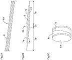
- FIG. 1 is a sectional view of a pneumatic tire in a width direction
- FIG. 2A is a plan view of a master roll
- FIG. 2B is a plan view of a sheet-like belt
- FIG. 2C is a perspective view of a cylindrical belt
- FIG. 3 is a plan view of an entire manufacturing device of a tire belt
- FIG. 4 is a plan view of a master roll table
- FIG. 5 is a view of a first hand when viewed in a direction indicated by an arrow A of FIG. 3 ;
- FIG. 6 is a view of a second hand when viewed in the direction indicated by the arrow A of FIG. 3 ;
- FIG. 7 is a plan view of a slip detector
- FIG. 8 is a plan view of a belt table
- FIG. 9 is a view of a rear portion of the belt table when viewed in a direction indicated by an arrow B of FIG. 8 ;
- FIG. 10 is a sectional view taken along a line C-C of FIG. 8 (sectional view in the vicinity of a rodless cylinder);
- FIG. 11 is a sectional view taken along a line D-D of FIG. 8 (sectional view in the vicinity of a buffer device);
- FIG. 12 is a view of a cutting device and pressing members when viewed in the direction indicated by the arrow A of FIG. 3 ;
- FIG. 13A is a view of a winding cylinder when viewed from radially outside and FIG. 13B is a view of the winding cylinder when viewed in an axial direction;
- FIG. 14 is a view of a winding cylinder of a modification when viewed from radially outside;
- FIG. 15 is a view of a winding device when viewed in an extending direction of a rack
- FIG. 16 is a view of the winding device when viewed in a direction indicated by an arrow E of FIG. 15 ;
- FIG. 17 is a view of a holding structure of a rotation shaft of the winding device (when viewed in the direction indicated by the arrow E of FIG. 15 );
- FIG. 18 is a view of a laminating device and a molding drum when viewed in a direction indicated by an arrow F of FIG. 3 ;
- FIG. 19 is a block diagram centered around a control portion
- FIGS. 20A to 20D are views showing a manner in which the master roll is fed from the master roll table to the belt table with arrows indicating a hand moving direction
- FIG. 20A being a view showing a manner in which the first hand and the second hand move in the feeding direction by a short distance
- FIG. 20B being a view showing a manner in which the second hand releases the master roll and moves backward in the feeding direction
- FIG. 20C being a view showing a manner in which the second hand holds the master roll again
- FIG. 20D being a view showing a manner in which the first hand and the second hand move again in the feeding direction by a short distance
- FIGS. 21A and 21B are views showing a manner in which a detection is made by the slip detector with arrows indicating a moving direction of the master roll and a rotation direction of a roller, FIG. 21A being a view showing a manner in which the slip detector detects that the master roll slips on the second hand and FIG. 21B being a view showing a manner in which the slip detector detects that the master roll is partially floating;
- FIGS. 22A to 22C are views showing a manner in which the sheet-like belt is cut out and moved to a belt winding position with arrows indicating moving directions of the cutting device and the belt table, FIG. 22A being a view showing a manner in which the master roll is fixed, FIG. 22B being a view showing a manner in which the master roll is cut, and FIG. 22C being a view showing a manner in which the belt table moves;
- FIG. 23A is a view of the belt table moved to the belt winding position and FIG. 23B is a view showing a movement of the winding device to a winding start position with an arrow indicating length measuring position and measuring direction of a laser displacement sensor;
- FIGS. 24A to 24C are views showing a manner in which the sheet-like belt is wound with arrows indicating a rotation direction and a moving direction of the winding cylinder, FIG. 24A being a view showing a manner in which a winding start tip of the sheet-like belt is pushed up, FIG. 24B being a view showing a manner in which the winding start tip of the sheet-like belt is inserted into a belt tip insertion hole of the winding cylinder, and FIG. 24C being a view showing a manner in which the winding cylinder moves by rotating;
- FIG. 25 is a view showing a manner in which the winding cylinder is pressed against a winding end tip of the sheet-like belt with arrows indicating moving directions of the winding cylinder;
- FIGS. 26A to 26D are views showing a manner in which the sheet-like belt is wound around the winding cylinder, FIG. 26A being a view showing a manner in which the sheet-like belt is wound by a first turn, FIG. 26B being a view showing a manner in which the sheet-like belt is wound by a second turn; FIG. 26C being a view showing a manner in which the sheet-like belt is wound by a third turn, and FIG. 26D being a view showing a manner in which the sheet-like belt is wound by a fourth turn; and
- FIG. 27 is a view showing a manner in which the cylindrical belt is molded with arrows indicating rotation directions of the molding drum and the winding cylinder.
- FIG. 1 An example of a pneumatic tire 1 is shown in FIG. 1 .
- the pneumatic tire 1 is a heavy load radial tire used in, for example, a truck or a bus.
- Bead portions 2 are provided on both sides of the pneumatic tire 1 in a width direction.
- the bead portion 2 includes a bead core 2 a formed of a circularly-wound steel wire and a bead filler 2 b made of rubber and provided on an outside of the bead core 2 a in a radial direction.
- a carcass ply 5 is bridged between the bead portions 2 on the both sides in the tire width direction.
- the carcass ply 5 is a sheet-like member formed by covering a large number of ply cords lined up in a direction orthogonal to a tire circumferential direction with rubber.
- the carcass ply 5 not only forms a framework shape of the pneumatic tire 1 between the bead portions 2 on the both sides in the tire width direction, but also wraps the bead portions 2 by being folded inside out in the tire width direction about the bead portions 2 .
- a sheet-like inner liner 6 having a rubber layer with low air permeability is laminated to an inner side of the carcass ply 5 .
- belts 8 are provided on an outside of the carcass ply 5 in a tire radial direction.
- a structure of the belt 8 will be described below.
- a tread rubber 3 having a contact patch is provided on an outside of the belt 8 in the tire radial direction.
- side wall rubbers 4 are provided on both sides of the carcass ply 5 in the tire width direction.
- members, such as a pad under belt and a chafer, are provided as a functional need of the pneumatic tire 1 arises.
- a cylindrical belt 8 c (see FIG. 2 ) is manufactured by winding the prepared sheet-like belt 8 b around a molding drum 64 (see FIG. 2 ). Because the pneumatic tire 1 has multiple belts 8 , multiple sheet-like belts 8 b are wound around the molding drum 64 one after another. Multiple cylindrical belts 8 c overlapping one another are thus manufactured. Subsequently, the tread rubber 3 is laminated to an outer diameter side of the cylindrical belts 8 c . A cylindrical tread ring formed of the multiple cylindrical belts 8 c and the tread rubber 3 is thus completed.
- the sheet-like inner liner 6 and the sheet-like carcass ply 5 are laminated onto another cylindrical drum.
- a cylindrical body called a primary case is thus completed.
- the annular bead portions 2 are set on both sides of the primary case in an axial direction.
- shaping is performed, by which the primary case is formed into a toroidal shape by inflating the primary case radially outward between the bead portions 2 on the both sides.
- the tread ring is laminated to an outer diameter side of a toroidally inflated portion of the primary case.
- turn-up is also performed, by which the carcass ply 5 is folded about the bead portions 2 .
- the side wall rubbers 4 are laminated to the toroidally inflated portion of the primary case from both sides in the axial direction. An unvulcanized tire is thus completed.
- the pneumatic tire 1 is completed by subjecting the unvulcanized tire to vulcanization molding in a mold.
- the cylindrical belt 8 c subjected to vulcanization forms the belt 8 of the pneumatic tire 1 .
- the manufacturing method described as above is a mere example and a modification, such as changing the order in part, can be made to the description above as a need arises.
- the side wall rubbers 4 may be laminated to predetermined positions after the bead portions 2 are set to the primary case and the turn-up is performed, followed by the shaping.
- the belt 8 is formed by covering multiple belt cords 9 (see FIG. 2 ) extending diagonally with respect to the tire circumferential direction with rubber.
- the belt cords 9 are made of steel.
- the belt cords 9 made of organic fiber are also available.
- At least one of the multiple belts 8 included in the pneumatic tire 1 is manufactured from the master roll 8 a and the sheet-like belt 8 b described in the following.
- the master roll 8 a is formed by covering the multiple belt cords 9 lined up parallel to one another with unvulcanized rubber. An extending direction of the belt cords 9 coincides with a longitudinal direction of the master roll 8 a.
- the sheet-like belt 8 b shown in FIG. 2B is cut out by cutting the master roll 8 a diagonally with respect to the longitudinal direction.
- Cut side portions 7 d which are cutting marks of the master roll 8 a , form both side portions of the sheet-like belt 8 b in a width direction.
- An extending direction of the cut side portions 7 d coincides with the longitudinal direction of the sheet-like belt 8 b .
- Portions which were both sides of the master roll 8 a in the width direction form inclined side portions 7 a with respect to the longitudinal direction of the sheet-like belt 8 b .
- the inclined side portions 7 a are parallel to the belt cords 9 .
- An angle produced between the longitudinal direction of the sheet-like belt 8 b and the belt cords 9 (this angle is equal to an angle produced between the longitudinal direction of the sheet-like belt 8 b and the inclined side portions 7 a and also equal to a cutting angle of the master roll 8 a with respect to the longitudinal direction) is small, and for example, in a range of 6° to 9° both inclusive.
- an angle produced between the longitudinal direction of the sheet-like belt 8 b and the belt cords 9 is small as above, a restraint force of the finished belt 8 in the tire radial direction becomes high.
- the sheet-like belt 8 b is wound around the molding drum 64 and forms the cylindrical belt 8 c.
- a device manufacturing a tire belt that is, the cylindrical belt 8 c used in the pneumatic tire 1 will be described.
- FIG. 3 An overall structure of a manufacturing device of a tire belt is shown in FIG. 3 .
- the manufacturing device of a tire belt has a master roll table 10 on which to place the master roll 8 a , a belt table 14 situated adjacent to the master roll table 10 and accepting the master roll 8 a fed from the master roll table 10 , a first hand 30 and a second hand 40 feeding the master roll 8 a from the master roll table 10 to the belt table 14 , and a cutting device 70 cutting out the sheet-like belt 8 b on the belt table 14 by cutting the master roll 8 a between the master roll table 10 and the belt table 14 .
- the manufacturing device of a tire belt has a winding cylinder 50 (also called a bobbin) around which to wind the sheet-like belt 8 b on the belt table 14 , a laminating device 60 to which the winding cylinder 50 wound with the sheet-like belt 8 b is transported and attached, and the molding drum 64 onto which the sheet-like belt 8 b unwound from the winding cylinder 50 attached to the laminating device 60 is laminated and molded into the cylindrical belt 8 c.
- a winding cylinder 50 also called a bobbin
- the master roll 8 a is placed on the master roll table 10 .
- a longitudinal direction of the master roll table 10 coincides with a feeding direction of the master roll 8 a indicated by an arrow G of FIG. 4 and inclines with respect to a longitudinal direction of the belt table 14 indicated by an arrow H of FIG. 4 .
- An edge 11 of the master roll table 10 situated adjacent to the belt table 14 inclines with respect to the longitudinal direction of the master roll table 10 and extends in a same direction as the longitudinal direction of the belt table 14 .
- An angle of inclination of the edge 11 with respect to the longitudinal direction of the master roll table 10 is equal to a cutting angle of the master roll 8 a with respect to the longitudinal direction.
- blow holes 12 lined up parallel to the edge 11 in one or more than one row are provided to the master roll table 10 in a portion on a forward side in the feeding direction.
- the blow holes 12 are connected to an unillustrated pipe under the master roll table 10 and the pipe is connected to an unillustrated air supply device. With this structure, air supplied from the air supply device passes through the pipe and blows out upward from the blow holes 12 .
- the first hand 30 is a device which holds a front part of the master roll 8 a in the feeding direction when the master roll 8 a is fed from the master roll table 10 to the belt table 14 .
- a first hand rail 32 extending in the feeding direction of the master roll 8 a is provided above the belt table 14 .
- the first hand 30 is allowed to move above and between the master roll table 10 and the belt table 14 along the first hand rail 32 .
- the first hand 30 has an air cylinder 31 as a lifting device, a single horizontal top plate 33 attached to the air cylinder 31 , and two hand portions 30 a and 30 b attached to a bottom surface of the top plate 33 .
- the two hand portions 30 a and 30 b are line up in the feeding direction of the master roll 8 a .
- the top plate 33 and the two hand portions 30 a and 30 b are guided by a guide 38 disposed between the air cylinder 31 and the top plate 33 and move up and down as one unit.
- the hand portion 30 a has a contact plate 36 disposed below the top plate 33 and apart from the top plate 33 .
- the contact plate 36 is fixed to the top plate 33 and moves up and down with the top plate 33 as one unit in association with a movement of the air cylinder 31 .
- the contact plate 36 is provided with multiple magnet holes 37 lined up in the feeding direction of the master roll 8 a.
- the hand portion 30 a has one air cylinder 34 as a lifting device attached to the top plate 33 and situated above the contact plate 36 , and multiple magnets 35 as attracting means attached to the air cylinder 34 .
- the multiple magnets 35 are lined up in the feeding direction of the master roll 8 a .
- the multiple magnets 35 move up and down as one unit in association with a movement of the air cylinder 34 .
- the multiple magnets 35 sink into respective magnet holes 37 in the contact plate 36 when they move down in association with a movement of the air cylinder 34 and rises above the contact plate 36 when they move up in association with a movement of the air cylinder 34 .
- the other hand portion 30 b has a same structure as the hand portion 30 a described above.
- the master roll 8 a having the steel belt cords 9 are attracted to the magnets 35 .
- the first hand 30 holds the master roll 8 a by forcing the master roll 8 a to float above the master roll table 10 and the belt table 14 by attraction.
- the master roll 8 a falls off the first hand 30 . In this manner, the first hand 30 releases the master roll 8 a.
- the second hand 40 is a device which holds a rear part (a rearward part trailing the front part in the feeding direction) of the master roll 8 a when the master roll 8 a is fed from the master roll table 10 to the belt table 14 .
- a second hand rail 42 extending in the feeding direction of the master roll 8 a is provided above the master roll table 10 .
- the second hand 40 is allowed to move along the second hand rail 42 .
- the second hand 40 has an air cylinder 41 as a lifting device, a single horizontal top plate 43 attached to the air cylinder 41 , and three hand portions 40 a , 40 b , and 40 c attached to a bottom surface of the top plate 43 .
- the three hand portions 40 a , 40 b , and 40 c are lined up in the feeding direction of the master roll 8 a .
- the top plate 43 and the three hand portions 40 a , 40 b , and 40 c are guided by a guide 49 disposed between the air cylinder 41 and the top plate 43 and move up and down as one unit.
- each of the hand portions 40 a , 40 b , and 40 c has a same structure as the hand portion 30 a of the first hand 30 . That is, each of the hand portions 40 a , 40 b , and 40 c has a contact plate 46 fixed to the top plate 43 and provided with multiple magnet holes 47 , an air cylinder 44 attached to the top plate 43 , and multiple magnets 45 attached to the air cylinder 44 .
- the contact plate 46 moves down and comes in close proximity to the master roll 8 a on the master roll table 10 in association with a movement of the air cylinder 41 and further the magnets 45 move down and sink into the magnet holes 47 of the contact plate 46 in association with a movement of the air cylinder 44 , the master roll 8 a is attracted to the magnets 45 .
- the second hand 40 holds the master roll 8 a by forcing the master roll 8 a to float above the master roll table 10 by attraction.
- the magnets 45 move up in association with a movement of the air cylinder 44 while the second hand 40 is holding the master roll 8 a or the contact plate 46 also moves up in association with a movement of the air cylinder 41 after the magnets 45 move up, the master roll 8 a falls off the second hand 40 . In this manner, the second hand 40 releases the master roll 8 a.
- the second hand 40 has a slip detector 48 which detects a slip when the master roll 8 a slips on the second hand 40 .
- the slip detector 48 is provided to, for example, a place between the two hand portions 40 a and 40 b.
- the slip detector 48 includes a roller 48 a , a rotary encoder 48 b , and a shaft 48 c functioning as a rotation shaft of the roller 48 a and the rotary encoder 48 b .
- the roller 48 a is provided to slightly protrude downward from the contact plate 46 of the hand portion 40 b.
- the roller 48 a of the slip detector 48 makes contact with the master roll 8 a .
- the roller 48 a rotates and the rotary encoder 48 b detects such a rotation.
- the slip detector 48 may be provided to the first hand 30 .
- the belt table 14 is a table on which to place a portion of the master roll 8 a fed from the master roll table 10 , and after the master roll 8 a is cut, it is a table on which to place the sheet-like belt 8 b cut out from the master roll 8 a .
- a longitudinal direction of the belt table 14 and the longitudinal direction of the sheet-like belt 8 b coincide with each other.
- a portion on a forward side in the feeding direction of the master roll 8 a is referred to as a front portion 14 a and a portion on the opposite side is referred to as a rear portion 14 b.
- multiple magnet holes 16 are lined up in the longitudinal direction of the belt table 14 at least on both sides of the belt table 14 in a width direction.
- an air cylinder 17 is disposed below each magnet hole 16 and a magnet 15 is attached to each air cylinder 17 .
- the magnet 15 moves up and goes into the magnet hole 16 or the magnet 15 moves down below the magnet hole 16 .
- the magnet 15 becomes capable of attracting the master roll 8 a and the sheet-like belt 8 b on the belt table 14 .
- the magnets 15 can be controlled independently to move up and down.
- Other attracting means capable of attracting the master roll 8 a and the sheet-like belt 8 b such as a suction device sucking air in, may be used instead of the magnets 15 .
- the rear portion 14 b of the belt table 14 is a portion on a winding start side when the sheet-like belt 8 b is wound around the winding cylinder 50 described below.
- a notch 18 is provided to an edge of the rear portion 14 b facing the master roll table 10 .
- an air cylinder 19 is disposed below the notch 18 and a push-up rod 20 is attached to the air cylinder 19 .
- the push-up rod 20 moves up above a top surface of the belt table 14 or moves down below the belt table 14 .
- the push-up rod 20 becomes capable of pushing up the sheet-like belt 8 b on the belt table 14 .
- a sensor hole 21 different from the magnet holes 16 opens at another place in the rear portion 14 b of the belt table 14 .
- a belt detection sensor 22 such as a nearby sensor, which detects the presence of the sheet-like belt 8 b when the sheet-like belt 8 b is on the belt table 14 , is provided below the sensor hole 21 .
- the air cylinder 17 , the magnets 15 , the air cylinder 19 , the push-up rod 20 , and the belt detection sensor 22 described above are allowed to move with the belt table 14 as one unit owing to a structure described in the following.
- the belt table 14 is allowed to move in a direction orthogonal to the longitudinal direction of the belt table 14 between a belt cut-out position at which the belt table 14 makes contact with or comes in close proximity to the edge 11 of the master roll table 10 and a belt winding position more distant from the master roll table 10 than the belt cut-out position.
- the belt cut-out position is a position of the belt table 14 when the sheet-like belt 8 b is cut out from the master roll 8 a .
- the belt winding position is a position of the belt table 14 when the sheet-like belt 8 b is wound around the winding cylinder 50 .
- a position of the belt table 14 indicated by a solid line is the belt cut-out position and a position of the belt table 14 indicated by an alternate long and two short dashes line is the belt winding position.
- a rodless cylinder 23 as a moving device is provided below the belt table 14 from the belt cut-out position to the belt winding position.
- a movable portion 23 a of the rodless cylinder 23 is allowed to move in a direction orthogonal to the longitudinal direction of the belt table 14 .
- the belt table 14 is allowed to move in a direction orthogonal to the longitudinal direction of the belt table 14 .
- the belt table 14 at the belt cut-out position is indicated by a solid line and the belt table 14 at the belt winding position is indicated by an alternate long and two short dashes line.
- the rodless cylinder 23 is provided to more than one point (for example, two points) in the longitudinal direction of the belt table 14 .
- the belt table 14 moves parallel to itself while keeping its posture. As is shown in FIG. 8 , the belt table 14 at the belt cut-out position and the belt table 14 at the belt winding position are parallel to each other.
- a buffer device 24 is fixed at each of the belt cut-out position and the belt winding position to ease an impact given when the belt table 14 moves to the respective positions.
- the buffer device 24 has, for example, a rod 24 a and a case 24 b .
- the rod 24 a of the buffer device 24 at the belt cut-out position protrudes toward the belt winding position and the rod 24 a of the buffer device 24 at the belt winding position protrudes toward the belt cut-out position.
- the belt table 14 at the belt cut-out position is indicated by a solid line and the belt table 14 at the belt winding position is indicated by an alternate long and two short dashes line.
- the buffer devices 24 as above are provided at multiple positions in the longitudinal direction of the belt table 14 .
- the buffer devices 24 are fixed below the belt table 14 .
- Stoppers 25 protruding downward are fixed to the belt table 14 at positions in the longitudinal direction corresponding to the respective buffer devices 24 . Hence, when the belt table 14 moves to the belt cut-out position or the belt winding position, the stopper 25 of the belt table 14 hits the buffer device 24 at the moved position, by which an impact is eased.
- the buffer devices 24 function also as a stopping device to stop the belt table 14 at a predetermined position.
- the cutting device 70 has a circular blade 71 which cuts the master roll 8 a and a device main body 73 which holds the blade 71 .
- an unillustrated long lower blade is provided between the master roll table 10 and the belt table 14 along the edge 11 of the master roll table 10 .
- the blade 71 and the device main body 73 move along a rail 74 provided above the belt table 14 in the longitudinal direction of the belt table 14 , which is a cutting direction of the master roll 8 a .
- the blade 71 rotates by running in contact with the long lower blade and thereby cuts the master roll 8 a .
- the sheet-like belt 8 b is thus cut out on the belt table 14 .
- Each pressing member 76 is a plate-shaped member having a bottom surface parallel to the top surface of the master roll table 10 and independently moved up and down by an air cylinder 77 . When the pressing members 76 move down, the pressing members 76 press the master roll 8 a against the master roll table 10 at positions along the edge 11 .
- the multiple pressing members 76 press the master roll 8 a in a portion closer to the master roll table 10 than the cutting position while the multiple magnets 15 attract the master roll 8 a in a portion closer to the belt table 14 than the cutting position.
- radial differences are given to an outside surface of the winding cylinder 50 by providing steps 54 to make the diameter smaller on one side and larger on the other side in the axial direction.
- a height of the steps 54 is equal to a thickness of the sheet-like belt 8 b wound around the winding cylinder 50 .
- the number of the steps 54 is determined as follows. That is, as is shown in FIG. 2B , the sheet-like belt 8 b has inclined regions 7 b , which are tapered regions having the inclined side portions 7 a , and a maximum width region 7 c which is a region having a maximum width without having the inclined side portion 7 a .
- the inclined regions 7 b are on both sides of the sheet-like belt 8 b in the longitudinal direction.
- the number of the steps 54 is a value found by subtracting one from the number of rotations (integer by rounding off to the closest whole number) necessary for the winding cylinder 50 to wind one entire inclined region 7 b completely.
- a belt tip insertion hole 52 opens in a small-diameter portion 51 a of the winding cylinder 50 .
- the belt tip insertion hole 52 is a hole in which to insert a tip end of the sheet-like belt 8 b when winding of the sheet-like belt 8 b around the winding cylinder 50 starts.
- a desirable shape of the belt tip insertion hole 52 is, as is shown in FIG. 13A , a shape in which both sides in a circumferential direction of the winding cylinder 50 form sides 52 a and 52 b extending in the axial direction of the winding cylinder 50 .
- a rotation shaft hole 53 in which to insert a rotation shaft 81 of a winding device 80 and a rotation shaft 61 of the laminating device 60 opens in the winding cylinder 50 at a position of a rotation shaft.
- the winding cylinder 50 is made of, for example, resin, and examples of the resin include but not limited to ABS resin and nylon. In addition, the winding cylinder 50 is hollow.
- a winding cylinder 150 having an outside surface formed of a single stepless curved surface as is shown in FIG. 14 may be used to wind the sheet-like belt 8 b . It is desirable that a belt tip insertion hole 52 same as the one described above also opens in the winding cylinder 150 of the modification.
- the winding cylinder 50 is attached to the winding device 80 shown in FIG. 15 and FIG. 16 .
- the winding device 80 has a rotary drive portion 84 formed of the rotation shaft 81 inserted into the rotation shaft hole 53 of the winding cylinder 50 , a servo motor 82 rotating the rotation shaft 81 , and a timing belt 83 coupling pullies respectively fixed to the rotation shaft 81 and a rotor of the servo motor 82 .
- the servo motor 82 operates, its power is transmitted to the rotation shaft 81 by the timing belt 83 and the winding cylinder 50 rotates with the rotation shaft 81 as one unit.
- the rotation shaft 81 extends parallel to the top surface of the belt table 14 in a direction orthogonal to the longitudinal direction of the belt table 14 .
- a direction of the rotation shaft of the winding cylinder 50 also becomes parallel to the top surface of the belt table 14 in a direction orthogonal to the longitudinal direction of the belt table 14 .
- the rotation shaft 81 is held by air cylinders 57 from both sides in a front-rear direction, which is a moving direction of the winding cylinder 50 .
- a constant pressure is applied to piston rods 57 a of the respective air cylinders 57 toward the rotation shaft 81 .
- the piston rods 57 a undergo displacement and the rotation shaft 81 shifts in the front-rear direction, by which the force applied to the winding cylinder 50 is released.
- the air cylinders 57 are not shown.
- the winding device 80 also has a ball screw 89 causing the rotary drive portion 84 to move up and down, and a servo motor 85 driving the ball screw 89 .
- the servo motor 85 operates, the rotary drive portion 84 coupled to a nut of the ball screw 89 moves up and down.
- the winding device 80 has a moving device moving the servo motor 85 and the rotary drive portion 84 as one unit in the longitudinal direction of the belt table 14 .
- the moving device of the winding device 80 has a rack 86 extending in the longitudinal direction of the belt table 14 next to the belt table 14 at the belt winding position, a pinion 87 meshed with the rack 86 , and a servo motor 88 rotating the pinion 87 .
- the servo motor 88 moves with the servo motor 85 and the rotary drive portion 84 as one unit along the rack 86 while rotating the pinon 87 . Consequently, the winding cylinder 50 attached to the rotation shaft 81 of the rotary drive portion 84 moves along the rack 86 in the longitudinal direction of the belt table 14 .
- the rack 86 is parallel to the belt table 14 at a high degree of accuracy.
- the winding cylinder 50 attached to the winding device 80 stands by at a waiting position which is a position close to the front portion 14 a of the belt table 14 .
- the servo motor 88 starts to operate. Accordingly, the winding cylinder 50 moves in the longitudinal direction of the belt table 14 to the winding start position close to the rear portion 14 b of the belt table 14 .
- the servo motor 82 and the servo motor 88 start to operate, by which the winding cylinder 50 winds up the sheet-like belt 8 b by moving from the winding start position to the waiting position while rotating.
- a laser displacement sensor 56 is fixed to the winding device 80 to protrude in a same direction as the rotation shaft 81 .
- the laser displacement sensor 56 is allowed to move with the winding cylinder 50 as one unit in the longitudinal direction of the belt table 14 , and passes above the sheet-like belt 8 b on the belt table 14 while moving.
- the laser displacement sensor 56 detects both ends of the sheet-like belt 8 b in the longitudinal direction (to be more exact, steps between a surface of the belt table 14 and a surface of the sheet-like belt 8 b ) while passing above the sheet-like belt 8 b .
- a control portion 90 is capable of finding a length of the sheet-like belt 8 b from a travel distance of the rotary drive portion 84 since the laser displacement sensor 56 detects one end of the sheet-like belt 8 b in the longitudinal direction until the laser displacement sensor 56 detects the other end.
- the laser displacement sensor 56 functions as a measuring device measuring a length of the sheet-like belt 8 b on the belt table 14 . It is desirable that the laser displacement sensor 56 is set to detect a position of the sheet-like belt 8 b at a center in the width direction. Alternatively, another measuring device capable of measuring a length of the sheet-like member 8 b on the belt table 14 may be used instead of the laser displacement sensor 56 .
- a worker attaches the winding cylinder 50 to the winding device 80 and removes the winding cylinder 50 from the winding device 80 when winding of the sheet-like belt 8 b ends. Hence, the worker can work while standing at the waiting position.
- the laminating device 60 and the molding drum 64 shown in FIG. 18 are devices to unwind the sheet-like belt 8 b from the winding cylinder 50 and molding the sheet-like belt 8 b into the circular belt 8 c.
- the laminating device 60 is a device to which the winding cylinder 50 is attached when the sheet-like belt 8 b is unwound from the winding cylinder 50 .
- the laminating device 60 has the rotatable rotation shaft 61 . By inserting the rotation shaft 61 into the rotation shaft hole 53 of the winding cylinder 50 , the winding cylinder 50 is attached to the laminating device 60 .
- the winding cylinder 50 attached to the laminating device 60 is rotatable.
- the molding drum 64 is a device molding the cylindrical belt 8 c and disposed to oppose the rotation shaft 61 of the laminating device 60 .
- the molding drum 64 is of a cylindrical shape and its rotation shaft is parallel to the rotation shaft 61 of the laminating device 60 .
- the molding drum 64 is connected to an unillustrated drive device. When the drive device operates, the molding drum 64 rotates. When the molding drum 64 rotates and starts to wind up the sheet-like belt 8 b from the winding cylinder 50 , the winding cylinder 50 is driven and starts to feed the sheet-like belt 8 b.
- the laminating device 60 and the molding drum 64 may be disposed at a place distant from the master roll table 10 , the belt table 14 , and the winding device 80 .
- the manufacturing device of a tire belt as above is controlled by the control portion 90 shown in FIG. 19 .
- the control portion 90 is electrically connected to respective portions enabling the manufacturing device to operate and capable of controlling the respective portions. Further, the control portion 90 is electrically connected to at least the slip detector 48 , the belt detection sensor 22 , and the laser displacement sensor 56 and is capable of controlling the respective portions according to detection results of at least these sensors.
- FIG. 19 shows some of the portions electrically connected to the control portion 90 .
- a manufacturing method of a tire belt described in the following can be performed under the control of the control portion 90 .
- the master roll 8 a is placed on the master roll table 10 . It is understood that a front end of the master roll 8 a in the feeding direction is along the edge 11 of the master roll table 10 and inclines with respect to the longitudinal direction of the master roll 8 a before feeding of the master roll 8 a described in the following starts.
- the first hand 30 and the second hand 40 feed the master roll 8 a placed on the master roll table 10 to the belt table 14 at the belt cut-out position.
- This feeding is performed by repeating feeding of a short distance and stopping of the feeding multiple times.
- the first hand 30 holds the front part of the master roll 8 a and the second hand 40 holds the rear part of the master roll 8 a . Because the first hand 30 and the second hand 40 attract the master roll 8 a by using the magnets 35 and 45 , respectively, the master roll 8 a floats above the master roll table 10 .
- the first hand 30 and the second hand 40 move in the feeding direction by a short distance simultaneously at a same speed as is shown in FIG. 20A , by which the master roll 8 a is fed by a short distance. Subsequently, the first hand 30 and the second hand 40 stop. Subsequently, while the first hand 30 is at rest while holding the master roll 8 a , the second hand 40 releases the master roll 8 a and moves backward in the feeding direction as is shown in FIG. 20B , and holds the master roll 8 a again as is shown in FIG. 20C . Subsequently, the first hand 30 and the second hand 40 move again in the feeding direction by a short distance simultaneously at a same speed as is shown in FIG. 20D , by which the master roll 8 a is fed by a short distance.
- a range forming a single sheet-like belt 8 b in the master roll 8 a on a forward side in the feeding direction is fed to the belt table 14 .
- the first hand 30 keeps holding the front part of the master roll 8 a from start to end of the feeding as above.
- the air supply device While the master roll 8 a is moving, the air supply device operates and air blows out upward from the blow holes 12 of the master roll table 10 . This air induces a floating force that acts on the master roll 8 a on the master roll table 10 .
- the master roll 8 a may possibly slip on the first hand 30 and the second hand 40 .
- the roller 48 a of the slip detector 48 rotates as is shown in FIG. 21A and the slip is detected. Accordingly, the control portion 90 gives an alarm or stops the feeding of the master roll 8 a.
- a slip can be detected even when the master roll 8 a slips while the first hand 30 alone is holding the master roll 8 a.
- the master roll 8 a in part may possibly float above the master roll table 10 when the tension becomes loose.
- the roller 48 a of the slip detector 48 rotates by making contact with a floating portion of the master roll 8 a while the secondhand 40 is moving backward in the feeding direction after the second hand 40 releases the master roll 8 a during the feeding of the master roll 8 a .
- the slip detector 48 detects that the master roll 8 a is floating. Accordingly, the control portion 90 gives an alarm or stops the feeding of the master roll 8 a.
- the first hand 30 and the second hand 40 release the master roll 8 a .
- the magnets 15 of the belt table 14 move up and attract both sides of the master roll 8 a in the width direction onto the belt table 14 .
- a single sheet-like belt 8 b is cut out by cutting the master roll 8 a once.
- This single sheet-like belt 8 b is a sheet-like belt 8 b for one full circle of tire.
- the multiple pressing members 76 move down from above the edge 11 of the master roll table 10 facing the belt table 14 first, and as is shown in FIG. 22A , press the master roll 8 a in a portion closer to the master roll table 10 than the cutting position. Consequently, the master roll 8 a is fixed so as not to shift by the multiple pressing members 76 on the side closer to the master roll table 10 than the cutting position and by the multiple magnets 15 on the side closer to the belt table 14 than the cutting position.
- the cutting device 70 cuts the master roll 8 a between the master roll table 10 and the belt table 14 while the master roll 8 a is fixed by the pressing members 76 and the magnets 15 .
- the master roll 8 a is cut along the edge 11 of the master roll table 10 in the longitudinal direction of the belt table 14 . Consequently, a portion of the master roll 8 a placed on the belt table 14 is cut out as a single sheet-like belt 8 b for one full circle of tire.
- the belt table 14 moves from the belt cut-out position to the belt winding position while carrying the single sheet-like belt 8 b .
- the belt table 14 moves while the cut-out single sheet-like belt 8 b is fixed by attracting the cut-out single sheet-like belt 8 b onto the belt table 14 by the magnets 15 .
- the magnets 15 keep attracting the master roll 8 a or the sheet-like belt 8 b onto the belt table 14 continuously before the master roll 8 a is cut.
- the winding device 80 to which is attached the winding cylinder 50 is at the waiting position.
- the winding device 80 starts to wind the sheet-like belt 8 b around the winding cylinder 50 after the belt table 14 moves to the belt winding position.
- the winding device 80 moves from the waiting position to the winding start position to start winding of the sheet-like belt 8 b around the winding cylinder 50 .
- the winding cylinder 50 is floating above the belt table 14 and the sheet-like belt 8 b.
- the laser displacement sensor 56 fixed to the winding device 80 measures a length of the sheet-like belt 8 b by passing above the sheet-like belt 8 b on the belt table 14 . It is desirable to measure a length on a straight line at a center of the sheet-like belt 8 b in the width direction.
- the control portion 90 makes a pass or fail determination as to the length of the sheet-like belt 8 b .
- the control portion 90 makes a pass determination, and a fail determination when the measured length falls outside the range.
- the winding device 80 moves to the winding start position and stops once. In a case where the control portion 90 makes a pass determination as to the length of the sheet-like belt 8 b , winding of the sheet-like belt 8 b around the winding cylinder 50 described in the following is started. Meanwhile, in a case where the control portion 90 makes a fail determination, the winding device 80 stays at the winding start position and generation of a failed product is notified.
- the push-up rod 20 moves up from below the belt table 14 and pushes up an end of the inclined region 7 b of the sheet-like belt 8 b on the side where the winding starts (referred to as “winding start tip”).
- the winding start tip of the sheet-like belt 8 b is inserted into the belt tip insertion hole 52 of the winding cylinder 50 as the winding cylinder 50 moves forward toward the waiting position by a short distance. Consequently, the winding start tip of the sheet-like belt 8 b can be substantially fixed to the winding cylinder 50 and winding of the sheet-like belt 8 b around the winding cylinder 50 can be started.
- the winding cylinder 50 moves in the longitudinal direction of the belt table 14 (that is, the longitudinal direction of the sheet-like belt 8 b ) by rotating about the rotation shaft 81 of the winding device 80 , by which the winding cylinder 50 winds up the sheet-like belt 8 b .
- the winding cylinder 50 moves from the winding start position toward the waiting position.
- the winding cylinder 50 moves while floating above the belt table 14 and winds up the sheet-like belt 8 b upward.
- the sheet-like belt 8 b is attracted onto the belt table 14 by the multiple magnets 15 lined up in the longitudinal direction and eventually attraction by the magnets 15 is cancelled one after another from the magnet 15 to which the winding cylinder 50 has moved (to be more specific, as the magnets 15 move down one after another). Consequently, the sheet-like belt 8 b comes off the belt table 14 from one portion to another where attraction is cancelled and is wound around the winding cylinder 50 .
- the sheet-like belt 8 b is wound around the winding cylinder 50 in multiple turns. As the winding progresses, a winding diameter increases by a thickness of the sheet-like belt 8 b wound around earlier. Hence, the control portion 90 prevents the sheet-like belt 8 b on the belt table 14 from being pulled hard by the winding cylinder 50 by reducing an angular velocity of a rotation of the winding cylinder 50 or increasing a moving speed of the winding cylinder 50 as the winding progresses.
- winding end tip When the winding cylinder 50 arrives a position of an end of the inclined region 7 b in the sheet-like belt 8 b on the side where the winding ends (referred to as “winding end tip”), the winding cylinder 50 which has been floating above the belt table 14 moves down as is shown in FIG. 25 and is pressed against the winding end tip of the sheet-like belt 8 b . Consequently, the winding end tip of the sheet-like belt 8 b firmly adheres to the winding cylinder 50 and the winding of the sheet-like belt 8 b around the winding cylinder 50 ends.
- the winding start tip of the sheet-like belt 8 b remains on the belt table 14 even when the winding cylinder 50 starts to move toward the waiting position by rotating. Accordingly, in a case where the belt detection sensor 22 detects the presence of the winding start tip of the sheet-like belt 8 b on the belt table 14 when the winding cylinder 50 has moved to a predetermined position, a failure in insertion of the winding start tip of the sheet-like belt 8 b into the belt tip insertion hole 52 can be determined. Accordingly, the control portion 90 stops a movement of the winding cylinder 50 and notifies the occurrence of an error.
- FIG. 26 A specific manner in which the sheet-like belt 8 b is wound around the winding cylinder 50 will be described by using FIG. 26 .
- the winding cylinder 50 is provided with the two steps 54 and therefore has the small-diameter portion 51 a formed on one side in the axial direction, a large-diameter portion 51 c formed on the other side in the axial direction, and an intermediate-diameter portion Sib having a diameter which is an intermediate diameter between the diameters of the small-diameter portion 51 a and the large-diameter portion 51 c .
- the small-diameter portion 51 a is a portion where the winding of the sheet-like belt 8 b starts.
- the winding cylinder 50 is rotated as many times as a sum of the number of the steps 54 provided to the winding cylinder 50 and one (that is, the number of surfaces having different diameters) to completely wind the entire inclined region 7 b of the sheet-like belt 8 b at the winding start tip.
- a narrow portion near the winding start tip in the inclined region 7 b of the sheet-like belt 8 b is wound around the small-diameter portion 51 a of the winding cylinder 50 in a first turn of the winding.
- An outer diameter of the sheet-like belt 8 b wound around the small-diameter portion 51 a is equal to an outer diameter of the intermediate-diameter portion 51 b.
- the sheet-like belt 8 b is wound over a portion including the sheet-like belt 8 b wound earlier around the winding cylinder 50 and a portion of the winding cylinder 50 having a larger diameter.
- the sheet-like belt 8 b is wound over a portion including the sheet-like belt 8 b wound around the small-diameter portion 51 a earlier and the intermediate-diameter portion 51 b of the winding cylinder 50 (this portion will be referred to as “second turn winding surface”).
- a diameter of the sheet-like belt 8 b wound around the small-diameter portion 51 a earlier and the diameter of the intermediate-diameter portion 51 b are equal.
- the sheet-like belt 8 b wound over the second turn winding surface including the foregoing portions is hard to become wrinkled.
- An outer diameter of the sheet-like belt 8 b wound over the second turn winding surface is equal to the outer diameter of the large-diameter portion 51 c.
- the sheet-like belt 8 b is wound over a portion including the sheet-like belt 8 b wound earlier over the second turn winding surface and the large-diameter portion 51 c of the winding cylinder 50 (this portion will be referred to as “third turn winding surface”).
- a diameter of the sheet-like belt 8 b wound earlier over the second turn winding surface and the diameter of the large-diameter portion 51 c are equal.
- the sheet-like belt 8 b wound over the third turn winding surface including the foregoing portions is hard to become wrinkled.
- winding of the inclined region 7 b at the winding start tip ends during the third turn of the winding.
- the maximum width region 7 c and the inclined region 7 b at the winding end tip are continuously wound.
- the maximum width region 7 c is wound over the sheet-like belt 8 b wound earlier over the third turn winding surface.
- the inclined region 7 b at the winding end tip to be wound next is wound over portions of the sheet-like belt 8 b wound earlier.
- the sheet-like belt 8 b can be constantly wound over a substantially flat or flat portion.
- the winding cylinder 50 wound with the single sheet-like belt 8 b is removed from the winding device 80 , transported, and attached to the laminating device 60 .
- the tip end of the sheet-like belt 8 b is pulled out from the winding cylinder 50 attached to the lamination device 60 and laminated to the molding drum 64 .
- the molding drum 64 starts to rotate in this state and the sheet-like belt 8 b is wound around the molding drum 64 from the winding cylinder 50 .
- the sheet-like belt 8 b unwound from the winding cylinder 50 is wound around the molding drum 64 in such a manner that the longitudinal direction coincides with the circumferential direction of the molding drum 64 .
- Lamination of the sheet-like belt 8 b to the molding drum 64 ends when the sheet-like belt 8 b is wound around the molding drum 64 to the rear end.
- the molding drum 64 rotates, for example, a little less than twice (that is, once to wind the inclined region 7 b at the tip end and the maximum width region 7 c and a little less than once to wind the inclined region 7 b at the rear end).
- the inclined side portions 7 a of the original sheet-like belt 8 b on both sides in the longitudinal direction match each other on a same line on the molding drum 64 as is shown in FIG.
- a single cylindrical belt 8 c is molded from a single sheet-like belt 8 b.
- the present invention includes feeding the master roll 8 a from the master roll table 10 to the belt table 14 , cutting out the sheet-like belt 8 b for one full circle of tire by cutting the master roll 8 a diagonally with respect to the longitudinal direction between the master roll table 10 and the belt table 14 , moving the belt table 14 carrying the cut-out sheet-like belt 8 b for one full circle of tire to the winding position of the sheet-like belt 8 b , winding the sheet-like belt 8 b for one full circle of tire around the single winding cylinder 50 at the winding position, unwinding the sheet-like belt 8 b from the winding cylinder 50 in a place facing the molding drum 64 and forming the cylindrical belt 8 c by winding the sheet-like belt 8 b around the molding drum 64 .
- the present invention provides a novel manufacturing method of a tire belt that can be formed by cutting the master roll 8 a only once.
- a single sheet-like belt 8 b is cut out by cutting the master roll 8 a only once. Hence, a step of forming an intermediate sheet by joining cut sheets obtained by cutting a master roll and a facility for this step required in the related art are no longer necessary. Consequently, manufacturing efficacy becomes satisfactory and a facility space can be saved.
- an angle produced between the longitudinal direction of the sheet-like belt 8 b and the belt cords 9 (and the inclined side portions 7 a ) falls within a range of 6° to 9° both inclusive.
- an angle produced between the longitudinal direction of the sheet-like belt 8 b and the inclined side portions 7 a is 6° or greater, the inclined side portions 7 a do not become too long.
- the inclined side portions 7 a of the sheet-like belt 8 b on the both sides in the longitudinal direction can be readily matched on a same line on the molding drum 64 during the molding.
- an angle produced between the longitudinal direction of the sheet-like belt 8 b and the belt cords 9 is 9° or less, a restraint force of the finished belt 8 in the tire radial direction becomes sufficiently high.
Landscapes
- Engineering & Computer Science (AREA)
- Mechanical Engineering (AREA)
- Textile Engineering (AREA)
- Tyre Moulding (AREA)
Applications Claiming Priority (3)
| Application Number | Priority Date | Filing Date | Title |
|---|---|---|---|
| JP2017-254639 | 2017-12-28 | ||
| JPJP2017-254639 | 2017-12-28 | ||
| JP2017254639A JP6993872B2 (ja) | 2017-12-28 | 2017-12-28 | タイヤ用ベルトの製造方法 |
Publications (2)
| Publication Number | Publication Date |
|---|---|
| US20190202158A1 US20190202158A1 (en) | 2019-07-04 |
| US11141944B2 true US11141944B2 (en) | 2021-10-12 |
Family
ID=64665565
Family Applications (1)
| Application Number | Title | Priority Date | Filing Date |
|---|---|---|---|
| US16/218,557 Active 2039-08-02 US11141944B2 (en) | 2017-12-28 | 2018-12-13 | Manufacturing method and manufacturing device of tire belt |
Country Status (4)
| Country | Link |
|---|---|
| US (1) | US11141944B2 (ja) |
| EP (1) | EP3505340A1 (ja) |
| JP (1) | JP6993872B2 (ja) |
| CN (1) | CN109968710B (ja) |
Families Citing this family (1)
| Publication number | Priority date | Publication date | Assignee | Title |
|---|---|---|---|---|
| JP7348828B2 (ja) * | 2019-12-13 | 2023-09-21 | Toyo Tire株式会社 | 空気入りタイヤ |
Citations (12)
| Publication number | Priority date | Publication date | Assignee | Title |
|---|---|---|---|---|
| US4769104A (en) * | 1986-11-11 | 1988-09-06 | Bridgestone Corporation | Apparatus for sticking a tire component member |
| JP2001232695A (ja) | 2000-02-22 | 2001-08-28 | Toyo Tire & Rubber Co Ltd | 未加硫タイヤのベルトの成型方法 |
| US20030051794A1 (en) * | 2001-01-12 | 2003-03-20 | Nobuyuki Suda | Tire construction member producing method and device therefor |
| JP2006281621A (ja) * | 2005-03-31 | 2006-10-19 | Bridgestone Corp | タイヤ用帯状部材の搬送装置及び接合装置 |
| US20070003649A1 (en) * | 2003-07-28 | 2007-01-04 | Kaagman Mattheus J | Tread application device |
| US20080066851A1 (en) * | 2004-05-28 | 2008-03-20 | Bridgestone Corporation | Bead Member Forming Method and Apparatus |
| US20120111473A1 (en) * | 2009-05-11 | 2012-05-10 | Bridgestone Corporation | Apparatus and method for producing tire |
| US20120234451A1 (en) * | 2011-03-18 | 2012-09-20 | Toyo Tire & Rubber Co., Ltd. | Pneumatic tire |
| US20140196834A1 (en) * | 2011-07-06 | 2014-07-17 | Jan Kornelis Grashuis | Apparatus and method for manufacturing a green tyre |
| US20140345784A1 (en) * | 2011-12-15 | 2014-11-27 | Pirelli Tyre S.P.A. | Method for controlling deposition of a layer of sealing polymeric material on a forming drum and process for producing self-sealing tyres for vehicle wheels |
| JP2017030172A (ja) | 2015-07-29 | 2017-02-09 | 東洋ゴム工業株式会社 | 空気入りタイヤの製造方法及び空気入りタイヤ |
| US20190160771A1 (en) * | 2017-11-29 | 2019-05-30 | The Goodyear Tire & Rubber Company | Method of forming a belt structure for a pneumatic tire |
Family Cites Families (16)
| Publication number | Priority date | Publication date | Assignee | Title |
|---|---|---|---|---|
| JP3662375B2 (ja) * | 1996-11-26 | 2005-06-22 | 横浜ゴム株式会社 | 帯状材料の供給方法及びその装置 |
| US7008495B2 (en) * | 2000-06-29 | 2006-03-07 | Pirelli Pneumatici S.P.A. | Method and plant for manufacturing a belt structure, a belt package, and a crown structure for a vehicle tire |
| JP2002120301A (ja) * | 2000-10-13 | 2002-04-23 | Yokohama Rubber Co Ltd:The | 帯状材料の供給・貼付け方法 |
| JP4556328B2 (ja) * | 2000-12-27 | 2010-10-06 | 横浜ゴム株式会社 | 帯状ゴム部材の搬送,転写方法及びその装置 |
| JP4576763B2 (ja) * | 2001-07-03 | 2010-11-10 | 横浜ゴム株式会社 | 金属コードをゴム状弾性材料で被覆した帯状材料の遊離裸コードの検出方法及びその装置 |
| WO2003101714A2 (fr) * | 2002-06-03 | 2003-12-11 | Societe De Technologie Michelin | Fabrication d’une structure de renforcement pour pneumatique avec controle volumetrique de la matrice |
| US20050183815A1 (en) * | 2004-02-25 | 2005-08-25 | Toshiyuki Tanaka | Tire ply forming apparatus and process |
| KR101140074B1 (ko) | 2004-03-18 | 2012-04-30 | 브이엠아이 홀랜드 비.브이. | 컷팅 장치 |
| JP4816860B2 (ja) * | 2004-11-26 | 2011-11-16 | 横浜ゴム株式会社 | シート状部材の成形方法及びその装置 |
| FR2966082B1 (fr) | 2010-10-13 | 2012-10-26 | Michelin Soc Tech | Pneumatique a armature de carcasse radiale pour vehicule de tourisme. |
| CN201872361U (zh) * | 2010-11-02 | 2011-06-22 | 天津赛象科技股份有限公司 | 钢丝帘布裁断机接取装置 |
| JP5695432B2 (ja) * | 2011-01-28 | 2015-04-08 | 住友ゴム工業株式会社 | ベルトプライの形成方法 |
| DE102012102222A1 (de) * | 2012-03-16 | 2013-09-19 | Continental Reifen Deutschland Gmbh | Verfahren für eine Positionskorrektur der Spitzen eines Reifengürtels beim Aufwickeln auf einer Reifenaufbautrommel |
| JP5995793B2 (ja) * | 2013-06-26 | 2016-09-21 | 東京製綱株式会社 | ストリップ状スチールコード |
| DE202013105825U1 (de) * | 2013-12-19 | 2014-01-22 | Karl Eugen Fischer Gmbh | Spleißvorrichtung zum Spleißen von Cordbandstreifen |
| DE102014211561A1 (de) * | 2014-06-17 | 2015-12-17 | Continental Reifen Deutschland Gmbh | Verfahren zum Herstellen einer Karkasseinlage |
-
2017
- 2017-12-28 JP JP2017254639A patent/JP6993872B2/ja active Active
-
2018
- 2018-09-30 CN CN201811156914.1A patent/CN109968710B/zh active Active
- 2018-12-13 US US16/218,557 patent/US11141944B2/en active Active
- 2018-12-14 EP EP18212593.0A patent/EP3505340A1/en not_active Withdrawn
Patent Citations (12)
| Publication number | Priority date | Publication date | Assignee | Title |
|---|---|---|---|---|
| US4769104A (en) * | 1986-11-11 | 1988-09-06 | Bridgestone Corporation | Apparatus for sticking a tire component member |
| JP2001232695A (ja) | 2000-02-22 | 2001-08-28 | Toyo Tire & Rubber Co Ltd | 未加硫タイヤのベルトの成型方法 |
| US20030051794A1 (en) * | 2001-01-12 | 2003-03-20 | Nobuyuki Suda | Tire construction member producing method and device therefor |
| US20070003649A1 (en) * | 2003-07-28 | 2007-01-04 | Kaagman Mattheus J | Tread application device |
| US20080066851A1 (en) * | 2004-05-28 | 2008-03-20 | Bridgestone Corporation | Bead Member Forming Method and Apparatus |
| JP2006281621A (ja) * | 2005-03-31 | 2006-10-19 | Bridgestone Corp | タイヤ用帯状部材の搬送装置及び接合装置 |
| US20120111473A1 (en) * | 2009-05-11 | 2012-05-10 | Bridgestone Corporation | Apparatus and method for producing tire |
| US20120234451A1 (en) * | 2011-03-18 | 2012-09-20 | Toyo Tire & Rubber Co., Ltd. | Pneumatic tire |
| US20140196834A1 (en) * | 2011-07-06 | 2014-07-17 | Jan Kornelis Grashuis | Apparatus and method for manufacturing a green tyre |
| US20140345784A1 (en) * | 2011-12-15 | 2014-11-27 | Pirelli Tyre S.P.A. | Method for controlling deposition of a layer of sealing polymeric material on a forming drum and process for producing self-sealing tyres for vehicle wheels |
| JP2017030172A (ja) | 2015-07-29 | 2017-02-09 | 東洋ゴム工業株式会社 | 空気入りタイヤの製造方法及び空気入りタイヤ |
| US20190160771A1 (en) * | 2017-11-29 | 2019-05-30 | The Goodyear Tire & Rubber Company | Method of forming a belt structure for a pneumatic tire |
Non-Patent Citations (1)
| Title |
|---|
| Yuzo Kuroki, JP-2006281621-A, machine translation. (Year: 2006). * |
Also Published As
| Publication number | Publication date |
|---|---|
| CN109968710B (zh) | 2021-03-12 |
| JP2019119100A (ja) | 2019-07-22 |
| CN109968710A (zh) | 2019-07-05 |
| EP3505340A1 (en) | 2019-07-03 |
| US20190202158A1 (en) | 2019-07-04 |
| JP6993872B2 (ja) | 2022-01-14 |
Similar Documents
| Publication | Publication Date | Title |
|---|---|---|
| US20080149258A1 (en) | Tire assembly applier with cutter mechanism | |
| US11141944B2 (en) | Manufacturing method and manufacturing device of tire belt | |
| EP2720858B1 (en) | Process and apparatus for building tyres for vehicle wheels | |
| US11161314B2 (en) | Manufacturing method and manufacturing device of tire belt | |
| US11141943B2 (en) | Winding method and winding cylinder of sheet member | |
| US11046039B2 (en) | Manufacturing method and manufacturing device of sheet-like belt | |
| US11420839B2 (en) | Winding method and winding device of sheet-like belt | |
| US10688745B2 (en) | Winding method and winding device for bead filler for tire | |
| US20190202652A1 (en) | Manufacturing method and manufacturing device of tire belt | |
| KR101739673B1 (ko) | 트랜스퍼 드럼 상에 타이어 컴포넌트들을 픽업하고 배치하기 위한 방법 | |
| CN109968702B (zh) | 轮胎构成部件的制造方法及轮胎构成部件的制造装置 | |
| JP5006767B2 (ja) | ゴム状シートの搬送巻取り方法、及びその装置 | |
| JP6589394B2 (ja) | 空気入りタイヤの製造方法及び製造装置 | |
| US11345106B2 (en) | Manufacturing method of tire component and manufacturing device of tire component | |
| CN113085238A (zh) | 生胎的制造方法 | |
| JP2019055578A (ja) | タイヤ形成方法 |
Legal Events
| Date | Code | Title | Description |
|---|---|---|---|
| AS | Assignment |
Owner name: TOYO TIRE & RUBBER CO., LTD., JAPAN Free format text: ASSIGNMENT OF ASSIGNORS INTEREST;ASSIGNOR:ITAKURA, JUNJI;REEL/FRAME:047762/0004 Effective date: 20181108 |
|
| FEPP | Fee payment procedure |
Free format text: ENTITY STATUS SET TO UNDISCOUNTED (ORIGINAL EVENT CODE: BIG.); ENTITY STATUS OF PATENT OWNER: LARGE ENTITY |
|
| STPP | Information on status: patent application and granting procedure in general |
Free format text: RESPONSE TO NON-FINAL OFFICE ACTION ENTERED AND FORWARDED TO EXAMINER |
|
| STPP | Information on status: patent application and granting procedure in general |
Free format text: NON FINAL ACTION MAILED |
|
| STPP | Information on status: patent application and granting procedure in general |
Free format text: RESPONSE TO NON-FINAL OFFICE ACTION ENTERED AND FORWARDED TO EXAMINER |
|
| STPP | Information on status: patent application and granting procedure in general |
Free format text: NOTICE OF ALLOWANCE MAILED -- APPLICATION RECEIVED IN OFFICE OF PUBLICATIONS |
|
| STPP | Information on status: patent application and granting procedure in general |
Free format text: AWAITING TC RESP., ISSUE FEE NOT PAID |
|
| STPP | Information on status: patent application and granting procedure in general |
Free format text: NOTICE OF ALLOWANCE MAILED -- APPLICATION RECEIVED IN OFFICE OF PUBLICATIONS |
|
| STPP | Information on status: patent application and granting procedure in general |
Free format text: PUBLICATIONS -- ISSUE FEE PAYMENT VERIFIED |
|
| STCF | Information on status: patent grant |
Free format text: PATENTED CASE |