US11123716B2 - Denitrification catalyst for vessel, using ceramic nanotubes grown on porous metal structure, and preparation method thereof - Google Patents
Denitrification catalyst for vessel, using ceramic nanotubes grown on porous metal structure, and preparation method thereof Download PDFInfo
- Publication number
- US11123716B2 US11123716B2 US16/312,742 US201716312742A US11123716B2 US 11123716 B2 US11123716 B2 US 11123716B2 US 201716312742 A US201716312742 A US 201716312742A US 11123716 B2 US11123716 B2 US 11123716B2
- Authority
- US
- United States
- Prior art keywords
- metal structure
- porous metal
- nanotubes
- oxide
- ceramic
- Prior art date
- Legal status (The legal status is an assumption and is not a legal conclusion. Google has not performed a legal analysis and makes no representation as to the accuracy of the status listed.)
- Active, expires
Links
Images


Classifications
-
- B—PERFORMING OPERATIONS; TRANSPORTING
- B01—PHYSICAL OR CHEMICAL PROCESSES OR APPARATUS IN GENERAL
- B01J—CHEMICAL OR PHYSICAL PROCESSES, e.g. CATALYSIS OR COLLOID CHEMISTRY; THEIR RELEVANT APPARATUS
- B01J23/00—Catalysts comprising metals or metal oxides or hydroxides, not provided for in group B01J21/00
- B01J23/70—Catalysts comprising metals or metal oxides or hydroxides, not provided for in group B01J21/00 of the iron group metals or copper
- B01J23/76—Catalysts comprising metals or metal oxides or hydroxides, not provided for in group B01J21/00 of the iron group metals or copper combined with metals, oxides or hydroxides provided for in groups B01J23/02 - B01J23/36
- B01J23/84—Catalysts comprising metals or metal oxides or hydroxides, not provided for in group B01J21/00 of the iron group metals or copper combined with metals, oxides or hydroxides provided for in groups B01J23/02 - B01J23/36 with arsenic, antimony, bismuth, vanadium, niobium, tantalum, polonium, chromium, molybdenum, tungsten, manganese, technetium or rhenium
- B01J23/847—Vanadium, niobium or tantalum or polonium
-
- B—PERFORMING OPERATIONS; TRANSPORTING
- B01—PHYSICAL OR CHEMICAL PROCESSES OR APPARATUS IN GENERAL
- B01J—CHEMICAL OR PHYSICAL PROCESSES, e.g. CATALYSIS OR COLLOID CHEMISTRY; THEIR RELEVANT APPARATUS
- B01J23/00—Catalysts comprising metals or metal oxides or hydroxides, not provided for in group B01J21/00
- B01J23/16—Catalysts comprising metals or metal oxides or hydroxides, not provided for in group B01J21/00 of arsenic, antimony, bismuth, vanadium, niobium, tantalum, polonium, chromium, molybdenum, tungsten, manganese, technetium or rhenium
- B01J23/20—Vanadium, niobium or tantalum
- B01J23/22—Vanadium
-
- B—PERFORMING OPERATIONS; TRANSPORTING
- B01—PHYSICAL OR CHEMICAL PROCESSES OR APPARATUS IN GENERAL
- B01J—CHEMICAL OR PHYSICAL PROCESSES, e.g. CATALYSIS OR COLLOID CHEMISTRY; THEIR RELEVANT APPARATUS
- B01J23/00—Catalysts comprising metals or metal oxides or hydroxides, not provided for in group B01J21/00
- B01J23/16—Catalysts comprising metals or metal oxides or hydroxides, not provided for in group B01J21/00 of arsenic, antimony, bismuth, vanadium, niobium, tantalum, polonium, chromium, molybdenum, tungsten, manganese, technetium or rhenium
-
- B—PERFORMING OPERATIONS; TRANSPORTING
- B01—PHYSICAL OR CHEMICAL PROCESSES OR APPARATUS IN GENERAL
- B01J—CHEMICAL OR PHYSICAL PROCESSES, e.g. CATALYSIS OR COLLOID CHEMISTRY; THEIR RELEVANT APPARATUS
- B01J23/00—Catalysts comprising metals or metal oxides or hydroxides, not provided for in group B01J21/00
- B01J23/70—Catalysts comprising metals or metal oxides or hydroxides, not provided for in group B01J21/00 of the iron group metals or copper
-
- B—PERFORMING OPERATIONS; TRANSPORTING
- B01—PHYSICAL OR CHEMICAL PROCESSES OR APPARATUS IN GENERAL
- B01J—CHEMICAL OR PHYSICAL PROCESSES, e.g. CATALYSIS OR COLLOID CHEMISTRY; THEIR RELEVANT APPARATUS
- B01J23/00—Catalysts comprising metals or metal oxides or hydroxides, not provided for in group B01J21/00
- B01J23/70—Catalysts comprising metals or metal oxides or hydroxides, not provided for in group B01J21/00 of the iron group metals or copper
- B01J23/76—Catalysts comprising metals or metal oxides or hydroxides, not provided for in group B01J21/00 of the iron group metals or copper combined with metals, oxides or hydroxides provided for in groups B01J23/02 - B01J23/36
- B01J23/84—Catalysts comprising metals or metal oxides or hydroxides, not provided for in group B01J21/00 of the iron group metals or copper combined with metals, oxides or hydroxides provided for in groups B01J23/02 - B01J23/36 with arsenic, antimony, bismuth, vanadium, niobium, tantalum, polonium, chromium, molybdenum, tungsten, manganese, technetium or rhenium
- B01J23/847—Vanadium, niobium or tantalum or polonium
- B01J23/8472—Vanadium
-
- B01J35/0013—
-
- B01J35/002—
-
- B01J35/026—
-
- B01J35/06—
-
- B—PERFORMING OPERATIONS; TRANSPORTING
- B01—PHYSICAL OR CHEMICAL PROCESSES OR APPARATUS IN GENERAL
- B01J—CHEMICAL OR PHYSICAL PROCESSES, e.g. CATALYSIS OR COLLOID CHEMISTRY; THEIR RELEVANT APPARATUS
- B01J35/00—Catalysts, in general, characterised by their form or physical properties
- B01J35/30—Catalysts, in general, characterised by their form or physical properties characterised by their physical properties
- B01J35/391—Physical properties of the active metal ingredient
- B01J35/395—Thickness of the active catalytic layer
-
- B—PERFORMING OPERATIONS; TRANSPORTING
- B01—PHYSICAL OR CHEMICAL PROCESSES OR APPARATUS IN GENERAL
- B01J—CHEMICAL OR PHYSICAL PROCESSES, e.g. CATALYSIS OR COLLOID CHEMISTRY; THEIR RELEVANT APPARATUS
- B01J35/00—Catalysts, in general, characterised by their form or physical properties
- B01J35/40—Catalysts, in general, characterised by their form or physical properties characterised by dimensions, e.g. grain size
- B01J35/45—Nanoparticles
-
- B—PERFORMING OPERATIONS; TRANSPORTING
- B01—PHYSICAL OR CHEMICAL PROCESSES OR APPARATUS IN GENERAL
- B01J—CHEMICAL OR PHYSICAL PROCESSES, e.g. CATALYSIS OR COLLOID CHEMISTRY; THEIR RELEVANT APPARATUS
- B01J35/00—Catalysts, in general, characterised by their form or physical properties
- B01J35/50—Catalysts, in general, characterised by their form or physical properties characterised by their shape or configuration
-
- B—PERFORMING OPERATIONS; TRANSPORTING
- B01—PHYSICAL OR CHEMICAL PROCESSES OR APPARATUS IN GENERAL
- B01J—CHEMICAL OR PHYSICAL PROCESSES, e.g. CATALYSIS OR COLLOID CHEMISTRY; THEIR RELEVANT APPARATUS
- B01J35/00—Catalysts, in general, characterised by their form or physical properties
- B01J35/50—Catalysts, in general, characterised by their form or physical properties characterised by their shape or configuration
- B01J35/58—Fabrics or filaments
-
- B—PERFORMING OPERATIONS; TRANSPORTING
- B01—PHYSICAL OR CHEMICAL PROCESSES OR APPARATUS IN GENERAL
- B01J—CHEMICAL OR PHYSICAL PROCESSES, e.g. CATALYSIS OR COLLOID CHEMISTRY; THEIR RELEVANT APPARATUS
- B01J35/00—Catalysts, in general, characterised by their form or physical properties
- B01J35/70—Catalysts, in general, characterised by their form or physical properties characterised by their crystalline properties, e.g. semi-crystalline
-
- B—PERFORMING OPERATIONS; TRANSPORTING
- B01—PHYSICAL OR CHEMICAL PROCESSES OR APPARATUS IN GENERAL
- B01J—CHEMICAL OR PHYSICAL PROCESSES, e.g. CATALYSIS OR COLLOID CHEMISTRY; THEIR RELEVANT APPARATUS
- B01J37/00—Processes, in general, for preparing catalysts; Processes, in general, for activation of catalysts
- B01J37/02—Impregnation, coating or precipitation
-
- B—PERFORMING OPERATIONS; TRANSPORTING
- B01—PHYSICAL OR CHEMICAL PROCESSES OR APPARATUS IN GENERAL
- B01J—CHEMICAL OR PHYSICAL PROCESSES, e.g. CATALYSIS OR COLLOID CHEMISTRY; THEIR RELEVANT APPARATUS
- B01J37/00—Processes, in general, for preparing catalysts; Processes, in general, for activation of catalysts
- B01J37/02—Impregnation, coating or precipitation
- B01J37/0201—Impregnation
-
- B—PERFORMING OPERATIONS; TRANSPORTING
- B01—PHYSICAL OR CHEMICAL PROCESSES OR APPARATUS IN GENERAL
- B01J—CHEMICAL OR PHYSICAL PROCESSES, e.g. CATALYSIS OR COLLOID CHEMISTRY; THEIR RELEVANT APPARATUS
- B01J37/00—Processes, in general, for preparing catalysts; Processes, in general, for activation of catalysts
- B01J37/02—Impregnation, coating or precipitation
- B01J37/0215—Coating
- B01J37/0225—Coating of metal substrates
- B01J37/0226—Oxidation of the substrate, e.g. anodisation
-
- B—PERFORMING OPERATIONS; TRANSPORTING
- B01—PHYSICAL OR CHEMICAL PROCESSES OR APPARATUS IN GENERAL
- B01J—CHEMICAL OR PHYSICAL PROCESSES, e.g. CATALYSIS OR COLLOID CHEMISTRY; THEIR RELEVANT APPARATUS
- B01J37/00—Processes, in general, for preparing catalysts; Processes, in general, for activation of catalysts
- B01J37/08—Heat treatment
-
- F—MECHANICAL ENGINEERING; LIGHTING; HEATING; WEAPONS; BLASTING
- F01—MACHINES OR ENGINES IN GENERAL; ENGINE PLANTS IN GENERAL; STEAM ENGINES
- F01N—GAS-FLOW SILENCERS OR EXHAUST APPARATUS FOR MACHINES OR ENGINES IN GENERAL; GAS-FLOW SILENCERS OR EXHAUST APPARATUS FOR INTERNAL-COMBUSTION ENGINES
- F01N3/00—Exhaust or silencing apparatus having means for purifying, rendering innocuous, or otherwise treating exhaust
- F01N3/08—Exhaust or silencing apparatus having means for purifying, rendering innocuous, or otherwise treating exhaust for rendering innocuous
- F01N3/10—Exhaust or silencing apparatus having means for purifying, rendering innocuous, or otherwise treating exhaust for rendering innocuous by thermal or catalytic conversion of noxious components of exhaust
- F01N3/18—Exhaust or silencing apparatus having means for purifying, rendering innocuous, or otherwise treating exhaust for rendering innocuous by thermal or catalytic conversion of noxious components of exhaust characterised by methods of operation; Control
- F01N3/20—Exhaust or silencing apparatus having means for purifying, rendering innocuous, or otherwise treating exhaust for rendering innocuous by thermal or catalytic conversion of noxious components of exhaust characterised by methods of operation; Control specially adapted for catalytic conversion
- F01N3/206—Adding periodically or continuously substances to exhaust gases for promoting purification, e.g. catalytic material in liquid form, NOx reducing agents
- F01N3/2066—Selective catalytic reduction [SCR]
-
- F—MECHANICAL ENGINEERING; LIGHTING; HEATING; WEAPONS; BLASTING
- F01—MACHINES OR ENGINES IN GENERAL; ENGINE PLANTS IN GENERAL; STEAM ENGINES
- F01N—GAS-FLOW SILENCERS OR EXHAUST APPARATUS FOR MACHINES OR ENGINES IN GENERAL; GAS-FLOW SILENCERS OR EXHAUST APPARATUS FOR INTERNAL-COMBUSTION ENGINES
- F01N3/00—Exhaust or silencing apparatus having means for purifying, rendering innocuous, or otherwise treating exhaust
- F01N3/08—Exhaust or silencing apparatus having means for purifying, rendering innocuous, or otherwise treating exhaust for rendering innocuous
- F01N3/10—Exhaust or silencing apparatus having means for purifying, rendering innocuous, or otherwise treating exhaust for rendering innocuous by thermal or catalytic conversion of noxious components of exhaust
- F01N3/24—Exhaust or silencing apparatus having means for purifying, rendering innocuous, or otherwise treating exhaust for rendering innocuous by thermal or catalytic conversion of noxious components of exhaust characterised by constructional aspects of converting apparatus
- F01N3/28—Construction of catalytic reactors
- F01N3/2803—Construction of catalytic reactors characterised by structure, by material or by manufacturing of catalyst support
-
- F—MECHANICAL ENGINEERING; LIGHTING; HEATING; WEAPONS; BLASTING
- F01—MACHINES OR ENGINES IN GENERAL; ENGINE PLANTS IN GENERAL; STEAM ENGINES
- F01N—GAS-FLOW SILENCERS OR EXHAUST APPARATUS FOR MACHINES OR ENGINES IN GENERAL; GAS-FLOW SILENCERS OR EXHAUST APPARATUS FOR INTERNAL-COMBUSTION ENGINES
- F01N3/00—Exhaust or silencing apparatus having means for purifying, rendering innocuous, or otherwise treating exhaust
- F01N3/08—Exhaust or silencing apparatus having means for purifying, rendering innocuous, or otherwise treating exhaust for rendering innocuous
- F01N3/10—Exhaust or silencing apparatus having means for purifying, rendering innocuous, or otherwise treating exhaust for rendering innocuous by thermal or catalytic conversion of noxious components of exhaust
- F01N3/24—Exhaust or silencing apparatus having means for purifying, rendering innocuous, or otherwise treating exhaust for rendering innocuous by thermal or catalytic conversion of noxious components of exhaust characterised by constructional aspects of converting apparatus
- F01N3/28—Construction of catalytic reactors
- F01N3/2803—Construction of catalytic reactors characterised by structure, by material or by manufacturing of catalyst support
- F01N3/2825—Ceramics
-
- B—PERFORMING OPERATIONS; TRANSPORTING
- B01—PHYSICAL OR CHEMICAL PROCESSES OR APPARATUS IN GENERAL
- B01D—SEPARATION
- B01D2255/00—Catalysts
- B01D2255/20—Metals or compounds thereof
- B01D2255/207—Transition metals
- B01D2255/20707—Titanium
-
- B—PERFORMING OPERATIONS; TRANSPORTING
- B01—PHYSICAL OR CHEMICAL PROCESSES OR APPARATUS IN GENERAL
- B01J—CHEMICAL OR PHYSICAL PROCESSES, e.g. CATALYSIS OR COLLOID CHEMISTRY; THEIR RELEVANT APPARATUS
- B01J21/00—Catalysts comprising the elements, oxides, or hydroxides of magnesium, boron, aluminium, carbon, silicon, titanium, zirconium, or hafnium
- B01J21/06—Silicon, titanium, zirconium or hafnium; Oxides or hydroxides thereof
- B01J21/063—Titanium; Oxides or hydroxides thereof
-
- B—PERFORMING OPERATIONS; TRANSPORTING
- B01—PHYSICAL OR CHEMICAL PROCESSES OR APPARATUS IN GENERAL
- B01J—CHEMICAL OR PHYSICAL PROCESSES, e.g. CATALYSIS OR COLLOID CHEMISTRY; THEIR RELEVANT APPARATUS
- B01J2235/00—Indexing scheme associated with group B01J35/00, related to the analysis techniques used to determine the catalysts form or properties
-
- B—PERFORMING OPERATIONS; TRANSPORTING
- B01—PHYSICAL OR CHEMICAL PROCESSES OR APPARATUS IN GENERAL
- B01J—CHEMICAL OR PHYSICAL PROCESSES, e.g. CATALYSIS OR COLLOID CHEMISTRY; THEIR RELEVANT APPARATUS
- B01J2235/00—Indexing scheme associated with group B01J35/00, related to the analysis techniques used to determine the catalysts form or properties
- B01J2235/30—Scanning electron microscopy; Transmission electron microscopy
-
- B—PERFORMING OPERATIONS; TRANSPORTING
- B01—PHYSICAL OR CHEMICAL PROCESSES OR APPARATUS IN GENERAL
- B01J—CHEMICAL OR PHYSICAL PROCESSES, e.g. CATALYSIS OR COLLOID CHEMISTRY; THEIR RELEVANT APPARATUS
- B01J2523/00—Constitutive chemical elements of heterogeneous catalysts
- B01J2523/10—Constitutive chemical elements of heterogeneous catalysts of Group I (IA or IB) of the Periodic Table
- B01J2523/15—Caesium
-
- B—PERFORMING OPERATIONS; TRANSPORTING
- B01—PHYSICAL OR CHEMICAL PROCESSES OR APPARATUS IN GENERAL
- B01J—CHEMICAL OR PHYSICAL PROCESSES, e.g. CATALYSIS OR COLLOID CHEMISTRY; THEIR RELEVANT APPARATUS
- B01J2523/00—Constitutive chemical elements of heterogeneous catalysts
- B01J2523/50—Constitutive chemical elements of heterogeneous catalysts of Group V (VA or VB) of the Periodic Table
- B01J2523/55—Vanadium
-
- B—PERFORMING OPERATIONS; TRANSPORTING
- B01—PHYSICAL OR CHEMICAL PROCESSES OR APPARATUS IN GENERAL
- B01J—CHEMICAL OR PHYSICAL PROCESSES, e.g. CATALYSIS OR COLLOID CHEMISTRY; THEIR RELEVANT APPARATUS
- B01J2523/00—Constitutive chemical elements of heterogeneous catalysts
- B01J2523/50—Constitutive chemical elements of heterogeneous catalysts of Group V (VA or VB) of the Periodic Table
- B01J2523/56—Niobium
-
- B—PERFORMING OPERATIONS; TRANSPORTING
- B01—PHYSICAL OR CHEMICAL PROCESSES OR APPARATUS IN GENERAL
- B01J—CHEMICAL OR PHYSICAL PROCESSES, e.g. CATALYSIS OR COLLOID CHEMISTRY; THEIR RELEVANT APPARATUS
- B01J2523/00—Constitutive chemical elements of heterogeneous catalysts
- B01J2523/60—Constitutive chemical elements of heterogeneous catalysts of Group VI (VIA or VIB) of the Periodic Table
- B01J2523/67—Chromium
-
- B—PERFORMING OPERATIONS; TRANSPORTING
- B01—PHYSICAL OR CHEMICAL PROCESSES OR APPARATUS IN GENERAL
- B01J—CHEMICAL OR PHYSICAL PROCESSES, e.g. CATALYSIS OR COLLOID CHEMISTRY; THEIR RELEVANT APPARATUS
- B01J2523/00—Constitutive chemical elements of heterogeneous catalysts
- B01J2523/80—Constitutive chemical elements of heterogeneous catalysts of Group VIII of the Periodic Table
- B01J2523/84—Metals of the iron group
-
- F—MECHANICAL ENGINEERING; LIGHTING; HEATING; WEAPONS; BLASTING
- F01—MACHINES OR ENGINES IN GENERAL; ENGINE PLANTS IN GENERAL; STEAM ENGINES
- F01N—GAS-FLOW SILENCERS OR EXHAUST APPARATUS FOR MACHINES OR ENGINES IN GENERAL; GAS-FLOW SILENCERS OR EXHAUST APPARATUS FOR INTERNAL-COMBUSTION ENGINES
- F01N2330/00—Structure of catalyst support or particle filter
- F01N2330/02—Metallic plates or honeycombs, e.g. superposed or rolled-up corrugated or otherwise deformed sheet metal
-
- F—MECHANICAL ENGINEERING; LIGHTING; HEATING; WEAPONS; BLASTING
- F01—MACHINES OR ENGINES IN GENERAL; ENGINE PLANTS IN GENERAL; STEAM ENGINES
- F01N—GAS-FLOW SILENCERS OR EXHAUST APPARATUS FOR MACHINES OR ENGINES IN GENERAL; GAS-FLOW SILENCERS OR EXHAUST APPARATUS FOR INTERNAL-COMBUSTION ENGINES
- F01N2330/00—Structure of catalyst support or particle filter
- F01N2330/06—Ceramic, e.g. monoliths
-
- F—MECHANICAL ENGINEERING; LIGHTING; HEATING; WEAPONS; BLASTING
- F01—MACHINES OR ENGINES IN GENERAL; ENGINE PLANTS IN GENERAL; STEAM ENGINES
- F01N—GAS-FLOW SILENCERS OR EXHAUST APPARATUS FOR MACHINES OR ENGINES IN GENERAL; GAS-FLOW SILENCERS OR EXHAUST APPARATUS FOR INTERNAL-COMBUSTION ENGINES
- F01N2590/00—Exhaust or silencing apparatus adapted to particular use, e.g. for military applications, airplanes, submarines
- F01N2590/02—Exhaust or silencing apparatus adapted to particular use, e.g. for military applications, airplanes, submarines for marine vessels or naval applications
-
- F—MECHANICAL ENGINEERING; LIGHTING; HEATING; WEAPONS; BLASTING
- F01—MACHINES OR ENGINES IN GENERAL; ENGINE PLANTS IN GENERAL; STEAM ENGINES
- F01N—GAS-FLOW SILENCERS OR EXHAUST APPARATUS FOR MACHINES OR ENGINES IN GENERAL; GAS-FLOW SILENCERS OR EXHAUST APPARATUS FOR INTERNAL-COMBUSTION ENGINES
- F01N2610/00—Adding substances to exhaust gases
- F01N2610/02—Adding substances to exhaust gases the substance being ammonia or urea
-
- Y—GENERAL TAGGING OF NEW TECHNOLOGICAL DEVELOPMENTS; GENERAL TAGGING OF CROSS-SECTIONAL TECHNOLOGIES SPANNING OVER SEVERAL SECTIONS OF THE IPC; TECHNICAL SUBJECTS COVERED BY FORMER USPC CROSS-REFERENCE ART COLLECTIONS [XRACs] AND DIGESTS
- Y02—TECHNOLOGIES OR APPLICATIONS FOR MITIGATION OR ADAPTATION AGAINST CLIMATE CHANGE
- Y02A—TECHNOLOGIES FOR ADAPTATION TO CLIMATE CHANGE
- Y02A50/00—TECHNOLOGIES FOR ADAPTATION TO CLIMATE CHANGE in human health protection, e.g. against extreme weather
- Y02A50/20—Air quality improvement or preservation, e.g. vehicle emission control or emission reduction by using catalytic converters
-
- Y—GENERAL TAGGING OF NEW TECHNOLOGICAL DEVELOPMENTS; GENERAL TAGGING OF CROSS-SECTIONAL TECHNOLOGIES SPANNING OVER SEVERAL SECTIONS OF THE IPC; TECHNICAL SUBJECTS COVERED BY FORMER USPC CROSS-REFERENCE ART COLLECTIONS [XRACs] AND DIGESTS
- Y02—TECHNOLOGIES OR APPLICATIONS FOR MITIGATION OR ADAPTATION AGAINST CLIMATE CHANGE
- Y02T—CLIMATE CHANGE MITIGATION TECHNOLOGIES RELATED TO TRANSPORTATION
- Y02T10/00—Road transport of goods or passengers
- Y02T10/10—Internal combustion engine [ICE] based vehicles
- Y02T10/12—Improving ICE efficiencies
Definitions
- the present invention relates to a denitrification catalyst for a vessel, using ceramic nanotubes grown on a porous metal structure, and a preparation method thereof, and more particularly, to a high-efficiency denitrification catalyst for a vessel, using ceramic nanotubes with a high specific surface area grown on a porous metal structure through anodic oxidation and including an active material highly dispersed as a nano-thin film layer on inner and outer surfaces of the ceramic nanotubes through a deposition or supporting process, and a preparation method thereof.
- Contaminants in the exhaust gas are compounds containing hydrocarbon and oxygen, and include nitrogen oxide (NO x ), sulfur oxide (SO x ), carbon monoxide (CO), etc. Therefore, an attempt to reduce the amount of hazardous gas emitted from the combustion system of a coal-fired thermal power plant, an incinerator, a vehicle, a vessel, etc. has been made around the world over several decades.
- the technologies used to effectively remove nitrogen oxide can be roughly classified into three types: firstly, a selective catalytic reduction (SCR) technology using both a catalyst and a reductant; secondly, a selective non-catalytic reduction (SNCR) technology using only a reductant without a catalyst; and thirdly, a Low-NO x Burner (LNB) technology configured to control combustion conditions in the combustion system.
- SCR selective catalytic reduction
- SNCR selective non-catalytic reduction
- LNB Low-NO x Burner
- the SCR technology among the three technologies is most effective.
- the nitrogen oxide removal efficiency is 90% or more, and the duration of use is estimated to be about 2 to 5 years.
- a denitrification catalyst used in the SCR technology is largely composed of an active metal (active site) and a support.
- the active metal mainly is in the form of oxides of vanadium, tungsten, molybdenum, etc.
- examples of the support include titania (TiO 2 ), alumina (Al 2 O 3 ), silica (SiO 2 ), and a mixture thereof.
- titania (TiO 2 ) is mainly used as the support of a catalyst used in the conventional SCR technology due to catalytic activity and toxicity.
- the above-described active metals in the form of oxides are supported in a ceramic support to prepare a denitrification catalyst, and the catalyst thus prepared is mixed with various additives such as a binder and the like and then subjected to injection molding to finally prepare a support in the form of a honeycomb, a plate, corrugation, etc. Then, when exhaust gas penetrates through the denitrification catalyst in the form of the support thus prepared, the denitrification catalyst is reacted with toxic gases such as nitrogen oxide to induce reduction, and thus the exhaust gas is converted to a harmless substance.
- Korean Registered Patent No. 10-0584961 relates to a preparation method of a selective reduction catalyst coating for denitrifying exhaust gas and a support prepared by the catalyst preparation method, and discloses a ceramic support in a honeycomb form which supports an active metal catalyst.
- a catalyst including an active metal supported on a ceramic (e.g. titania) powder support is mixed with an additive such as a binder, a reinforcing material, etc., and then multistage processes including kneading, injection, molding, etc. are performed. Therefore, the preparation process is highly complex, and it is difficult to perform production, installation, and maintenance works due to a large amount of scattering dust generated during the preparation process.
- a denitrification catalyst using the ceramic support in the form of a honeycomb, etc. exhibits somewhat reduced denitrification efficiency because exhaust gas penetrates through the denitrification catalyst in one direction for a short period of retention, and it is also difficult to regenerate a denitrification catalyst fouled by carbonization or ammonium salts.
- the present inventors have ardently conducted research to solve the above-described problems of a denitrification catalyst for a vessel according to the present invention, using ceramic nanotubes grown on a porous metal structure and including an active metal highly dispersed as a nano-thin film layer on inner and outer surfaces of the ceramic nanotubes through a deposition or supporting process, and a preparation method thereof, and found that a novel, economical, and high-efficiency catalyst for denitrifying exhaust gas in a vessel may be prepared by the processes of: manufacturing a metal structure made of a titanium or aluminum metal in a three-dimensional shape rather than in an existing powder or honeycomb form and having a plurality of pores formed such that exhaust gas penetrates through the pores in multiple directions; growing ceramic nanotubes with a high specific surface area on the metal structure through anodic oxidation; and highly dispersing a small amount of an active metal as a nano-thin film layer on inner and outer surfaces of the ceramic nanotubes through a deposition or supporting process. Therefore, the present invention has been completed
- the present invention is directed to providing a high-efficiency denitrification catalyst for a vessel, which is prepared by growing ceramic nanotubes on the surface of the metal structure through anodic oxidation and highly dispersing a small amount of an active metal as a nano-thin film layer on inner and outer surfaces of the ceramic nanotubes through a deposition or supporting process, so that excellent economic feasibility and excellent catalytic performance are exhibited, and a preparation method thereof.
- a denitrification catalyst for a vessel using ceramic nanotubes grown on a porous metal structure, which includes: a porous metal structure having a plurality of pores formed between metal supports such that exhaust gas penetrates through the pores in multiple directions; ceramic nanotubes grown on the porous metal structure through anodic oxidation; and an active material uniformly and highly dispersed as a nano-thin film layer on inner and outer surfaces of the ceramic nanotubes through a deposition or supporting process.
- a method of preparing a denitrification catalyst for a vessel, using ceramic nanotubes grown on a porous metal structure through anodic oxidation which includes: i) manufacturing a porous metal structure allowing exhaust gas to penetrate through the structure in multiple directions; ii) preparing ceramic nanotubes on a surface of the porous metal structure through anodic oxidation; iii) highly dispersing, through a deposition or supporting process, an active material as a nano-thin film layer or nanoparticles on the porous metal structure including the ceramic nanotubes grown thereon; iv) drying the porous metal structure including the active material highly dispersed as a nano-thin film layer or nanoparticles on a surface of the ceramic nanotube through a deposition or supporting process; and v) firing the dried porous metal structure to finally prepare a denitrification catalyst.
- a denitrification catalyst according to the present invention using ceramic nanotubes grown on a porous metal structure and including an active metal highly dispersed as a nano-thin film layer on inner and outer surfaces of the ceramic nanotubes through a deposition or supporting process, uses a porous metal structure with a high specific surface area having a plurality of pores formed such that exhaust gas or gas penetrates through the pores in multiple directions and manufactured in a three-dimensional shape such as the form of a mesh, a foil, or a wire rather than in a powder or honeycomb form, so that the system for denitrifying exhaust gas can be more easily produced, installed, and maintained. Also, since additives such as a binder, a reinforcing material, etc. used in the manufacture of the structure in a powder or honeycomb form are not used, better catalytic performance can be achieved even with a small amount of expensive active metal.
- the denitrification catalyst according to the present invention can be applied to various fields including a power plant, an incinerator, the paper industry, the cement industry, the glass industry, a large-sized diesel vehicle, a diesel agricultural machinery, a railway vehicle engine, an industrial small/medium-sized power generator engine, etc. as well as a vessel.
- the shape of the porous metal structure included in the denitrification catalyst for a vessel according to the present invention can be varied to take the form of a circle, a rectangle, etc. in accordance with the structure of a denitrification system for a vessel, the denitrification catalyst can be minimally and optimally installed in a limited space in a vessel, the installation is easy, and maintenance is convenient.
- FIG. 1 is an image of a porous metal structure manufactured based on titanium or aluminum in the form of a mesh, a foil, or a wire according to an embodiment of the present invention.
- FIG. 2 is an image of ceramic nanotubes grown on a porous metal structure through anodic oxidation according to an embodiment of the present invention.
- FIG. 3 is a set of images illustrating a method of highly dispersing an active metal as a nano-thin film layer through a deposition or supporting process according to an embodiment of the present invention.
- FIG. 4 is a flow chart illustrating the sequence of a preparation method of a high-efficiency denitrification catalyst for a vessel, in which an active metal is highly dispersed on ceramic nanotubes grown on a porous metal structure through a deposition or supporting process, according to an embodiment of the present invention.
- FIG. 5A is a set of the SEM images and EDS element distribution maps of titania nanotubes and an active metal dispersed on the nanotubes according to an embodiment of the present invention
- FIG. 5B is a table illustrating elemental abundance.
- FIG. 6 is a graph of the performance evaluation results illustrating that a SCR catalyst (metal-based SCR catalyst) using a porous metal structure according to an embodiment of the present invention exhibits a higher conversion rate of NO x than that of a conventional SCR catalyst (ceramic-based SCR catalyst) using a ceramic support.
- FIG. 7 is a table illustrating the comparative analysis of advantages and disadvantages of a SCR catalyst using a porous metal structure according to an embodiment of the present invention and a conventional SCR catalyst using a ceramic support.
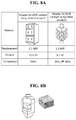
- FIG. 8A is a table illustrating the comparative analysis of sizes of a reactor for a SCR catalyst using a porous metal structure according to an embodiment of the present invention and a reactor for a conventional SCR catalyst using a ceramic support
- FIG. 8B is an image of a reactor equipped with a SCR catalyst using a metal structure.
- a high-efficiency denitrification catalyst for a vessel according to an embodiment of the present invention in which an active metal is highly dispersed on ceramic nanotubes grown on a porous metal structure through a deposition or supporting process, includes: a porous metal structure having a plurality of pores formed between metal supports such that exhaust gas penetrates through the pores in multiple directions; ceramic nanotubes grown on the porous metal structure through anodic oxidation; and an active material uniformly and highly dispersed as a nano-thin film layer on inner and outer surfaces of the ceramic nanotubes through a deposition or supporting process.
- the denitrification catalyst for a vessel according to the present invention is differentiated by the fact that a three-dimensional metal structure including ceramic nanotubes, which is an integration of ceramic nanotubes and a metal structure where the ceramic nanotubes were grown on a surface of the metal structure through anodic oxidation, is manufactured, and a small amount of an active metal is highly dispersed as a nano-thin film layer on inner and outer surfaces of the nanotubes through thin film deposition.
- the denitrification catalyst is differentiated by the fact that ceramic nanotubes are immersed in a solution in which an active metal precursor is dissolved so as to include the active metal highly dispersed on inner and outer surfaces of the nanotubes.
- the porous metal structure according to the present invention which is a metal structure in a three-dimensional shape rather than in a powder or honeycomb form, may be manufactured by a simplified process compared to a catalyst in the form of a honeycomb, a plate, corrugation, etc., which is prepared through multistage processes including kneading, injection, molding, etc. using a conventional powder catalyst and additives, and thus the production, installation, and maintenance are made easy.
- the metal structure in a three-dimensional shape may be realized in various shapes such as a circle, a rectangle, etc., and thus the structure and shape of a denitrification system may be varied in accordance with a limited space in a vessel. Therefore, a denitrification catalyst system optimized for a vessel space, for example, a SCR catalyst for denitrifying exhaust gas in a vessel may be prepared.
- the porous metal structure may be manufactured from titanium, aluminum, or an alloy thereof in the form of a mesh, a foil, or a wire.
- metal structure in the form of a mesh or a foil only one type of structure in the form of a mesh or a foil may be used, or it may include a plurality of structural types, a mesh or a foil, by having one type stacked on top of the other type.
- the metal structure in the form of a wire may be in the form of demister in which the wire is configured in a regular or irregular direction.
- the physical shapes, such as a length, a height, a width, etc., of the metal structure in the form of a mesh, a foil, or a wire may be varied to form various shapes such as a circle, a rectangle, etc.
- the form of the metal structure used to prepare the denitrification catalyst for a vessel according to the present invention may be varied in accordance with the spatial structure in which a denitrification system for a vessel is installed.
- FIG. 1 is an image of a porous metal structure manufactured in the form of a mesh, a foil, or a wire according to an embodiment of the present invention.
- the porous metal structure manufactured in the form of a mesh, a foil, or a wire is a porous metal structure in a three-dimensional form, which has a plurality of pores formed such that exhaust gas penetrates through the pores in multiple directions.
- FIG. 2 is an image of ceramic nanotubes grown on a porous metal structure through anodic oxidation according to an embodiment of the present invention.
- the anodic oxidation for preparing ceramic nanotubes with a high specific surface area may be performed by using, as the two counter electrodes in an electrolyte solution, platinum or carbon as a negative electrode and the porous metal structure as a positive electrode, and applying a constant voltage to the two electrodes through a direct-current power supplier.
- FIG. 3 is a set of images illustrating a method of highly dispersing an active metal as a nano-thin film layer through a deposition or supporting process according to an embodiment of the present invention.
- an active metal is highly dispersed as a nano-thin film layer on inner and outer surfaces of the ceramic nanotubes grown on the porous metal structure through anodic oxidation, by depositing the active metal on the nanotubes through thin film deposition or by supporting the active metal on the nanotubes using an active metal precursor solution.
- FIG. 3(A) is an image of a thin film deposition system
- FIG. 3(B) is an image illustrating a method of coating inner and outer surfaces of the nanotubes with an active metal using an atomic layer deposition system
- FIG. 3(C) is an image illustrating a method of supporting an active metal on inner and outer surfaces of nanotubes by immersing the nanotubes in an active metal precursor solution.
- the active metal is highly dispersed as a nano-thin film layer on inner and outer surfaces of the ceramic nanotubes through thin film deposition commonly used in the semiconductor manufacturing process.
- the thin film deposition include physical vapor deposition, chemical vapor deposition, and atomic layer deposition, and any one of them may be used.
- the active metal may be supported on ceramic nanotubes using a precursor solution prepared by dissolving the active metal precursor in distilled water and an organic solvent.
- a denitrification catalyst with excellent performance may be prepared.
- FIG. 4 is a flow chart illustrating the sequence of a preparation method of a denitrification catalyst for a vessel, in which an active metal is highly dispersed as a nano-thin film layer on ceramic nanotubes grown on a porous metal structure through a deposition or supporting process, according to an embodiment of the present invention.
- the ceramic nanotubes may be titania nanotubes or alumina nanotubes which are prepared from a titanium or aluminum metal through anodic oxidation.
- the active metal to be deposited or supported on the ceramic nanotubes may include a main active metal and an auxiliary active metal.
- vanadium oxide may be used, and as the auxiliary active metal, tungsten oxide, molybdenum oxide, cobalt oxide, iron oxide, chromium oxide, copper oxide, manganese oxide, nickel oxide, cesium oxide, niobium oxide, etc. may be used, but the present invention is not limited thereto.
- the active metal may be included in an amount of 0.1 to 10.0 wt % with respect to 100 wt % of the ceramic nanotubes.
- the porous metal structure has a porosity of 60% or more.
- the porous metal structure needs to have a degree of porosity above a certain level.
- the ceramic nanotube according to the present invention preferably has a specific surface area of 500 to 1,000 m 2 /g, a pore size of 500 to 5000 ⁇ , and a length of 500 nm to 5 ⁇ m.
- FIG. 5A is a set of the SEM images and EDS element distribution maps of titania nanotubes and an active metal dispersed on the nanotubes according to an embodiment of the present invention
- FIG. 5B is a table illustrating elemental abundance.
- FIG. 6 is a graph of the performance evaluation results illustrating that a SCR catalyst (metal-based SCR catalyst) using a porous metal structure according to an embodiment of the present invention exhibits a higher conversion rate of NO x than that of a conventional SCR catalyst (ceramic-based SCR catalyst) using a ceramic support.
- FIG. 7 is a table illustrating the comparative analysis of advantages and disadvantages of a SCR catalyst using a porous metal structure according to an embodiment of the present invention and a conventional SCR catalyst using a ceramic support.
- FIG. 8A is a table illustrating the comparative analysis of sizes of a reactor for a SCR catalyst using a porous metal structure according to an embodiment of the present invention and a reactor for a conventional SCR catalyst using a ceramic support
- FIG. 8B is an image of a reactor equipped with a SCR catalyst using a metal structure.
- the structure of a system for denitrifying exhaust gas may be easily varied and downsized such that it takes up a minimum space in a limited space in a vessel. Also, the system is easily installed, replaced, and maintained by applying a cartridge type catalyst to the SCR catalyst reactor, and thus Capex and Opex may be reduced to maximize profits.
- a method of preparing a denitrification catalyst for a vessel, using ceramic nanotubes grown on a porous metal structure through anodic oxidation which includes:
- porous metal structure including the active material highly dispersed as a nano-thin film layer or nanoparticles on a surface of the ceramic nanotube through a deposition or supporting process;
- the porous metal structure may be manufactured from a titanium or aluminum metal in the form of a mesh, a foil or a wire such that exhaust gas penetrates through the structure in multiple directions rather than in one direction.
- metal structure in the form of a mesh or a foil only one type of structure in the form of a mesh or a foil may be used, or it may include a plurality of structural types, a mesh or a foil, by having one type stacked on top of the other type.
- the metal structure in the form of a wire may be in the form of demister in which the wire is configured in a regular or irregular direction.
- the physical shapes, such as a length, a height, a width, an angle, etc., of the metal structure in the form of a mesh, a foil, or a wire may be varied in accordance with the structure of a denitrification system.
- the anodic oxidation for preparing ceramic nanotubes may be performed by using, as the two counter electrodes in an electrolyte solution, platinum or carbon as a negative electrode and the porous metal structure as a positive electrode, and applying a constant voltage to the two electrodes through a direct-current power supplier.
- An electrolyte used in the anodic oxidation is preferably an aqueous 0.1 to 1.0 M hydrofluoric acid solution, and an aqueous mixed solution of ethylene glycol or glycerol and 0.1 to 1.0 M ammonium fluoride may also be used as the electrolyte.
- ammonium sulfate 0.5 to 2 M ammonium sulfate, phosphoric acid, or sodium hydroxide may also be added as an additional additive.
- the anodic oxidation is preferably performed for 10 to 60 minutes.
- a voltage of 10 to 80 V is preferably applied to two electrodes.
- the anodic oxidation needs to be performed under conditions with optimized electrolyte concentration, applied voltage, and time in order to obtain the optimum shape of ceramic nanotube.
- the active metal or active material As a nano-thin film layer on inner and outer surfaces of the ceramic nanotubes, thin film deposition commonly used in the semiconductor manufacturing process is used, and the thin film deposition may be performed through a deposition technology such as atomic layer deposition, physical vapor deposition, chemical vapor deposition, etc.
- an active metal precursor may be dissolved in a solution to prepare a precursor solution.
- a supporting process is performed.
- the supporting process of the active metal may be performed by various methods, that is, by spreading, spraying, or supporting the active metal on the surface of the porous metal structure.
- an active metal precursor may be included in an amount of 0.1 to 10.0 wt % with respect to 100 wt % of the ceramic nanotubes.
- the porous metal structure on which the active metal has been supported on the surfaces of ceramic nanotubes may be dried in a drying furnace at 100 to 120° C. for 1 to 3 hours.
- the porous metal structure thus dried may be thermally treated by firing at 400 to 600° C. for 3 to 6 hours.
- the form of ceramic nanotubes is converted from amorphous oxides to crystalline oxides with a specific crystal structure, and active metal components are thermally treated so as to have a form of metal oxide.
- the thermal treatment is a process for crystallizing an amorphous oxide layer to form an anatase structure and is preferably performed at 400 to 600° C.
- the thermal treatment is performed at less than 400° C., it may be difficult to form an anatase structure through crystallization, and when the thermal treatment is performed at greater than 600° C., a rutile structure may be formed.
- Crystals formed by the thermal treatment affect the contaminant removal efficiency, and when crystals are present mainly in an anatase structure, the crystals effectively react with contaminants.
- the thermal treatment is preferably performed for 3 to 6 hours.
- the active metal in the form of a precursor in thin film deposition or to use the active metal as a precursor solution prepared by mixing with a solvent. Also, it is preferable that the active metal highly dispersed as a nano-thin film layer through a deposition or supporting process take the form of oxide after the thermal treatment through firing.
- the active metal may be deposited as a nano-thin film layer with a thickness of several nanometers on inner and outer surfaces of ceramic nanotubes through thin film deposition using an active metal precursor.
- a precursor solution prepared by mixing the active metal precursor with a solvent may be used to support the active metal on ceramic nanotubes.
- the solvent is preferably distilled water or an organic solvent such as ethanol, etc.
- the step iii) may be repeated in the same manner.
- the active metal may be more uniformly and highly dispersed on inner and outer surfaces of the ceramic nanotubes grown on the porous metal structure.
- the drying may be performed at 100 to 120° C. for 1 to 3 hours.
- the thermal treatment through firing may be performed at 400 to 600° C. for 3 to 6 hours.
- the drying and firing processes may be performed to remove moisture and impurities from the precursor solution and convert amorphous oxides into active crystalline oxides.
- the denitrification catalyst for a vessel using ceramic nanotubes grown on a porous metal structure according to the present invention is composed of an inlet through which exhaust gas is introduced and an outlet through which exhaust gas is discharged at a rear of the inlet.
- the active metal may be highly dispersed as a nano-thin film layer on nanotubes in the inlet through a deposition or supporting process, and an odor neutralizer may be applied onto nanotubes located in the outlet.
- the denitrification catalyst may allow exhaust gas introduced in one direction to firstly penetrate through the inlet in which the active metal is supported so as to remove contaminants, and then allow the gas from which the contaminants are removed to penetrate through the outlet coated with an odor neutralizer so as to remove an odor of gas and exhibit the corrosion resistant effect.
- the odor neutralizer may include a titanium or zirconium metal oxide.
- a titanium metal structure in the form of a mesh, a foil, or a wire was anodized using an aqueous 0.5 M hydrofluoric acid solution at 20 V for 20 minutes (an electrolyte is maintained at a constant temperature of 25° C.), then dried in a dryer at 120° C. for 2 hours, and thermally treated under an oxygen atmosphere at 500° C. for 3 hours to manufacture a porous metal structure on which TiO 2 nanotubes were grown.
- the shape of the TiO 2 nanotubes manufactured under the above condition was confirmed by a scanning electron microscope (SEM). As a result, it was confirmed that the TiO 2 nanotubes were uniformly grown with a constant shape of a diameter of 100 nm, a thickness of 20 nm, and a length of 1 to 2 In addition, it was confirmed through X-ray diffraction that the crystal structure of amorphous TiO 2 nanotubes was converted into an anatase structure after thermal treatment under an oxygen atmosphere.
- SEM scanning electron microscope
- an aqueous precursor solution containing a 0.06 M vanadium precursor and 0.5 M oxalic acid was prepared, and a porous titanium metal structure with TiO 2 nanotube growth was impregnated with the precursor solution.
- the impregnation was repeated several times in the same manner to support a predetermined amount of an active metal precursor on the surfaces of TiO 2 nanotubes, and the resultant structures were dried at 120° C. for 2 hours and thermally treated through firing at 500° C. for 4 hours to finally obtain the structure in which an active metal was supported on inner and outer surfaces of TiO 2 nanotubes.
- vanadium oxide which is an active metal
- vanadium oxide which is an active metal
- the porous titanium metal structure manufactured with a size of a diameter of 50 mm and a length of 100 mm was used to finally prepare a denitrification catalyst for a vessel through Examples 1 and 2.
- the catalytic performance of the denitrification catalyst prepared under conditions as shown in Table 1 below was measured.
- the SCR catalyst using ceramic nanotubes grown on a porous metal structure according to the present invention exhibits excellent productivity and excellent economic feasibility and can be applied as a denitrification catalyst to various fields including a power plant, an incinerator, the paper industry, the cement industry, the glass industry, a large-sized diesel vehicle, a diesel agricultural machinery, a railroad engine, an industrial small/medium-sized power generator engine, etc. as well as a vessel.
- the SCR catalyst can be minimally and optimally installed in a limited space in a vessel and conveniently maintained; therefore, it can be applied in a vessel field, specifically as a denitrification catalyst for a vessel.
Landscapes
- Chemical & Material Sciences (AREA)
- Engineering & Computer Science (AREA)
- Chemical Kinetics & Catalysis (AREA)
- Materials Engineering (AREA)
- Organic Chemistry (AREA)
- Toxicology (AREA)
- Health & Medical Sciences (AREA)
- Combustion & Propulsion (AREA)
- Mechanical Engineering (AREA)
- General Engineering & Computer Science (AREA)
- Thermal Sciences (AREA)
- Ceramic Engineering (AREA)
- Physics & Mathematics (AREA)
- Catalysts (AREA)
- Dispersion Chemistry (AREA)
Applications Claiming Priority (3)
| Application Number | Priority Date | Filing Date | Title |
|---|---|---|---|
| KR10-2016-0077617 | 2016-06-21 | ||
| KR1020160077617A KR101733171B1 (ko) | 2016-06-21 | 2016-06-21 | 다공극성 금속 구조체 상에 성장된 세라믹 나노튜브를 이용한 선박용 탈질 촉매 및 그의 제조방법 |
| PCT/KR2017/006542 WO2017222306A1 (ko) | 2016-06-21 | 2017-06-21 | 다공극성 금속 구조체 상에 성장된 세라믹 나노튜브를 이용한 선박용 탈질 촉매 및 그의 제조방법 |
Publications (2)
| Publication Number | Publication Date |
|---|---|
| US20190217279A1 US20190217279A1 (en) | 2019-07-18 |
| US11123716B2 true US11123716B2 (en) | 2021-09-21 |
Family
ID=60163723
Family Applications (1)
| Application Number | Title | Priority Date | Filing Date |
|---|---|---|---|
| US16/312,742 Active 2038-09-22 US11123716B2 (en) | 2016-06-21 | 2017-06-21 | Denitrification catalyst for vessel, using ceramic nanotubes grown on porous metal structure, and preparation method thereof |
Country Status (3)
| Country | Link |
|---|---|
| US (1) | US11123716B2 (ko) |
| KR (1) | KR101733171B1 (ko) |
| WO (1) | WO2017222306A1 (ko) |
Families Citing this family (6)
| Publication number | Priority date | Publication date | Assignee | Title |
|---|---|---|---|---|
| KR101733171B1 (ko) * | 2016-06-21 | 2017-05-08 | 한국생산기술연구원 | 다공극성 금속 구조체 상에 성장된 세라믹 나노튜브를 이용한 선박용 탈질 촉매 및 그의 제조방법 |
| KR102090726B1 (ko) * | 2017-12-14 | 2020-04-28 | 한국생산기술연구원 | 코팅 슬러리를 이용한 선택적 촉매 환원용 금속 구조체 기반 탈질 촉매 및 이의 제조방법 |
| KR102097550B1 (ko) * | 2018-10-12 | 2020-05-26 | 영남대학교 산학협력단 | 배가스 탈질 폐촉매를 이용한 수퍼캐패시터의 제조방법 |
| CN110624560B (zh) * | 2019-09-17 | 2020-08-04 | 吉林师范大学 | 一种用于光-芬顿联合催化的FeVO4/TiO2多孔催化剂膜层材料及其制备方法 |
| US10974225B1 (en) * | 2020-01-17 | 2021-04-13 | Zhejiang Nhu Company Ltd. | Metal oxide coated ceramic corrugated plate catalyst, preparation and application in preparation of key intermediates of citral |
| KR102433175B1 (ko) * | 2020-09-22 | 2022-08-18 | 한국전력공사 | 다공성 금속구조체 촉매를 이용한 산성가스 포집 시스템 |
Citations (5)
| Publication number | Priority date | Publication date | Assignee | Title |
|---|---|---|---|---|
| KR100584961B1 (ko) | 1999-11-10 | 2006-05-29 | 에스케이 주식회사 | 배연탈질용 선택적 환원 촉매의 코팅방법 및 이의방법으로 제조된 지지체 |
| US20100006134A1 (en) * | 2004-03-19 | 2010-01-14 | Nippon Oil Corporation | Nanotube-shaped titania and process for producing the same |
| KR20100055839A (ko) | 2008-11-18 | 2010-05-27 | 한국전기연구원 | 판상의 양극산화 나노다공질 산화물 세라믹 막을 포함하는 복합재료 막 및 이를 이용한 다기능 필터 |
| KR20140119331A (ko) | 2013-03-29 | 2014-10-10 | 고려대학교 산학협력단 | 나노촉매 필터 및 그의 제조방법 |
| KR20150062611A (ko) | 2013-11-29 | 2015-06-08 | 한국기계연구원 | 메탈폼의 제조방법, 이에 의해 제조된 메탈폼 및 상기 메탈폼으로 이루어지는 배기가스 정화 필터용 촉매 담체 |
Family Cites Families (1)
| Publication number | Priority date | Publication date | Assignee | Title |
|---|---|---|---|---|
| KR101733171B1 (ko) * | 2016-06-21 | 2017-05-08 | 한국생산기술연구원 | 다공극성 금속 구조체 상에 성장된 세라믹 나노튜브를 이용한 선박용 탈질 촉매 및 그의 제조방법 |
-
2016
- 2016-06-21 KR KR1020160077617A patent/KR101733171B1/ko active Active
-
2017
- 2017-06-21 WO PCT/KR2017/006542 patent/WO2017222306A1/ko not_active Ceased
- 2017-06-21 US US16/312,742 patent/US11123716B2/en active Active
Patent Citations (5)
| Publication number | Priority date | Publication date | Assignee | Title |
|---|---|---|---|---|
| KR100584961B1 (ko) | 1999-11-10 | 2006-05-29 | 에스케이 주식회사 | 배연탈질용 선택적 환원 촉매의 코팅방법 및 이의방법으로 제조된 지지체 |
| US20100006134A1 (en) * | 2004-03-19 | 2010-01-14 | Nippon Oil Corporation | Nanotube-shaped titania and process for producing the same |
| KR20100055839A (ko) | 2008-11-18 | 2010-05-27 | 한국전기연구원 | 판상의 양극산화 나노다공질 산화물 세라믹 막을 포함하는 복합재료 막 및 이를 이용한 다기능 필터 |
| KR20140119331A (ko) | 2013-03-29 | 2014-10-10 | 고려대학교 산학협력단 | 나노촉매 필터 및 그의 제조방법 |
| KR20150062611A (ko) | 2013-11-29 | 2015-06-08 | 한국기계연구원 | 메탈폼의 제조방법, 이에 의해 제조된 메탈폼 및 상기 메탈폼으로 이루어지는 배기가스 정화 필터용 촉매 담체 |
Non-Patent Citations (5)
| Title |
|---|
| Gu, Yun-Jang et al., "Technical Development of Modulization for the Compact SCR Catalyst corresponding to IMO Tier III", 2016 The Korean Society of Industrial and Engineering Chemistry Spring Meeting and Conference, May 3, 2016, Presentation Materials pp. 1-4. |
| International Search Report for PCT/KR2017/006542 dated Sep. 28, 2017 from Korean Intellectual Property Office. |
| Kim, Hyun-Seung et al., "Fabrication and Characterization of Functionally Graded Nano-Micro Porous Titanium Surface by Anodizing", Journal of Biomedical Materials Research Part B: Applied Biomaterials, Feb. 2009, pp. 427-435, vol. 88B, No. 2. |
| Kim, Nam-Gyoung et al., "Development of a New Type Eco-friendly Marine SCR Catalyst for the IMO Tier III Implementation", 2016 KOSECC, Spring Conference, May 26, 2016, Presentation Materials pp. 1-3. |
| Kim, Nam-Gyoung et al., "Development on New Catalyst Technology for Compact SCR Modularization for Ship", The Korean Society of Industrial and Engineering Chemistry 2016 Spring Meeting and Conference, Apr. 29, 2016, Presentation Materials pp. 1-4. |
Also Published As
| Publication number | Publication date |
|---|---|
| US20190217279A1 (en) | 2019-07-18 |
| KR101733171B1 (ko) | 2017-05-08 |
| WO2017222306A1 (ko) | 2017-12-28 |
Similar Documents
| Publication | Publication Date | Title |
|---|---|---|
| US11123716B2 (en) | Denitrification catalyst for vessel, using ceramic nanotubes grown on porous metal structure, and preparation method thereof | |
| JP6402336B2 (ja) | アンモニア分解触媒 | |
| KR102090726B1 (ko) | 코팅 슬러리를 이용한 선택적 촉매 환원용 금속 구조체 기반 탈질 촉매 및 이의 제조방법 | |
| KR102684593B1 (ko) | V 및 Sb 함유 복합 산화물을 포함하는 선택적 촉매 환원 (SCR) 촉매, 그의 제조 방법, 및 질소 산화물 제거를 위한 그의 용도 | |
| US10183246B2 (en) | Method for preparing a catalyzed fabric filter and a catalyzed fabric filter | |
| TWI406708B (zh) | Ammonia decomposition catalyst and the catalyst caused by ammonia exhaust treatment | |
| JP6047477B2 (ja) | 脱硝触媒、およびその製造方法 | |
| EP1484109B1 (en) | Catalyst for removing nitrogen oxides, method for production thereof and method for removing nitrogen oxides | |
| US8114369B2 (en) | Catalyst containing platinum and palladium for the selective reduction of NOx with hydrogen (H2-SCR) | |
| JPWO2013021506A1 (ja) | 熱化学水分解用レドックス材料及び水素製造方法 | |
| KR101891233B1 (ko) | 구조체의 표면에 형성된 촉매층을 포함하는 질소산화물 제거용 촉매, 이의 제조방법 및 용도 | |
| US20090264283A1 (en) | Stabilized Iridium and Ruthenium Catalysts | |
| US20090263300A1 (en) | Stabilized Iridium and Ruthenium Catalysts | |
| KR101659419B1 (ko) | 나노입자 담지 촉매의 제조방법 | |
| KR101565986B1 (ko) | 미세패턴을 가지는 scr 촉매 및 금형 제조방법 | |
| KR101565976B1 (ko) | 탄소재료에 바나듐을 담지하는 방법 | |
| KR20180064929A (ko) | 다공극성 세라믹 3차원 입체 망상 구조체를 이용한 선박용 탈질 촉매 및 그의 제조방법 | |
| EP2177257A1 (en) | Catalyst containing platinum on a support consisting of nano-crystal magnesium oxide and cerium dioxide towards H2-SCR | |
| KR101826222B1 (ko) | 촉매 활성 물질이 담지된 그래핀 슬러리를 포함하는 scr 촉매의 제조방법 | |
| KR102742238B1 (ko) | 폴리올 공정을 이용한 선택적 환원 촉매의 제조방법 | |
| JP2014144424A (ja) | アンモニア分解用触媒 | |
| KR20230123097A (ko) | 탈질 촉매 및 이의 제조 방법 | |
| Zhang et al. | Superior Low-Temperature Activity and So2 Tolerance of Mesh-Supported V2o5-Wo3/Tio2 Nanosheet Array Catalysts for Efficient Removal of Nox | |
| HK1175738B (en) | Deactivation-resistant catalyst for selective catalyst reduction of nox | |
| HK1175738A1 (en) | Deactivation-resistant catalyst for selective catalyst reduction of nox |
Legal Events
| Date | Code | Title | Description |
|---|---|---|---|
| AS | Assignment |
Owner name: KOREA INSTITUTE OF INDUSTRIAL TECHNOLOGY, KOREA, REPUBLIC OF Free format text: ASSIGNMENT OF ASSIGNORS INTEREST;ASSIGNORS:LIM, DONGHA;JUNG, UOOCHANG;JEONG, HAEYOUNG;AND OTHERS;REEL/FRAME:047844/0565 Effective date: 20181220 Owner name: KOREA INSTITUTE OF INDUSTRIAL TECHNOLOGY, KOREA, R Free format text: ASSIGNMENT OF ASSIGNORS INTEREST;ASSIGNORS:LIM, DONGHA;JUNG, UOOCHANG;JEONG, HAEYOUNG;AND OTHERS;REEL/FRAME:047844/0565 Effective date: 20181220 |
|
| FEPP | Fee payment procedure |
Free format text: ENTITY STATUS SET TO UNDISCOUNTED (ORIGINAL EVENT CODE: BIG.); ENTITY STATUS OF PATENT OWNER: SMALL ENTITY |
|
| FEPP | Fee payment procedure |
Free format text: ENTITY STATUS SET TO SMALL (ORIGINAL EVENT CODE: SMAL); ENTITY STATUS OF PATENT OWNER: SMALL ENTITY |
|
| STPP | Information on status: patent application and granting procedure in general |
Free format text: DOCKETED NEW CASE - READY FOR EXAMINATION |
|
| STPP | Information on status: patent application and granting procedure in general |
Free format text: NON FINAL ACTION MAILED |
|
| STPP | Information on status: patent application and granting procedure in general |
Free format text: RESPONSE TO NON-FINAL OFFICE ACTION ENTERED AND FORWARDED TO EXAMINER |
|
| STPP | Information on status: patent application and granting procedure in general |
Free format text: NOTICE OF ALLOWANCE MAILED -- APPLICATION RECEIVED IN OFFICE OF PUBLICATIONS |
|
| STCF | Information on status: patent grant |
Free format text: PATENTED CASE |
|
| MAFP | Maintenance fee payment |
Free format text: PAYMENT OF MAINTENANCE FEE, 4TH YR, SMALL ENTITY (ORIGINAL EVENT CODE: M2551); ENTITY STATUS OF PATENT OWNER: SMALL ENTITY Year of fee payment: 4 |