US11123030B2 - Controller for imaging apparatus - Google Patents
Controller for imaging apparatus Download PDFInfo
- Publication number
- US11123030B2 US11123030B2 US16/463,570 US201716463570A US11123030B2 US 11123030 B2 US11123030 B2 US 11123030B2 US 201716463570 A US201716463570 A US 201716463570A US 11123030 B2 US11123030 B2 US 11123030B2
- Authority
- US
- United States
- Prior art keywords
- controller
- gantry
- arm assembly
- disposed
- upright
- Prior art date
- Legal status (The legal status is an assumption and is not a legal conclusion. Google has not performed a legal analysis and makes no representation as to the accuracy of the status listed.)
- Active
Links
Images


Classifications
-
- A—HUMAN NECESSITIES
- A61—MEDICAL OR VETERINARY SCIENCE; HYGIENE
- A61B—DIAGNOSIS; SURGERY; IDENTIFICATION
- A61B6/00—Apparatus or devices for radiation diagnosis; Apparatus or devices for radiation diagnosis combined with radiation therapy equipment
- A61B6/44—Constructional features of apparatus for radiation diagnosis
- A61B6/4429—Constructional features of apparatus for radiation diagnosis related to the mounting of source units and detector units
- A61B6/4435—Constructional features of apparatus for radiation diagnosis related to the mounting of source units and detector units the source unit and the detector unit being coupled by a rigid structure
-
- A—HUMAN NECESSITIES
- A61—MEDICAL OR VETERINARY SCIENCE; HYGIENE
- A61B—DIAGNOSIS; SURGERY; IDENTIFICATION
- A61B6/00—Apparatus or devices for radiation diagnosis; Apparatus or devices for radiation diagnosis combined with radiation therapy equipment
- A61B6/02—Arrangements for diagnosis sequentially in different planes; Stereoscopic radiation diagnosis
- A61B6/025—Tomosynthesis
-
- A—HUMAN NECESSITIES
- A61—MEDICAL OR VETERINARY SCIENCE; HYGIENE
- A61B—DIAGNOSIS; SURGERY; IDENTIFICATION
- A61B6/00—Apparatus or devices for radiation diagnosis; Apparatus or devices for radiation diagnosis combined with radiation therapy equipment
- A61B6/04—Positioning of patients; Tiltable beds or the like
- A61B6/0407—Supports, e.g. tables or beds, for the body or parts of the body
- A61B6/0414—Supports, e.g. tables or beds, for the body or parts of the body with compression means
-
- A—HUMAN NECESSITIES
- A61—MEDICAL OR VETERINARY SCIENCE; HYGIENE
- A61B—DIAGNOSIS; SURGERY; IDENTIFICATION
- A61B6/00—Apparatus or devices for radiation diagnosis; Apparatus or devices for radiation diagnosis combined with radiation therapy equipment
- A61B6/46—Arrangements for interfacing with the operator or the patient
- A61B6/461—Displaying means of special interest
- A61B6/462—Displaying means of special interest characterised by constructional features of the display
-
- A—HUMAN NECESSITIES
- A61—MEDICAL OR VETERINARY SCIENCE; HYGIENE
- A61B—DIAGNOSIS; SURGERY; IDENTIFICATION
- A61B6/00—Apparatus or devices for radiation diagnosis; Apparatus or devices for radiation diagnosis combined with radiation therapy equipment
- A61B6/50—Apparatus or devices for radiation diagnosis; Apparatus or devices for radiation diagnosis combined with radiation therapy equipment specially adapted for specific body parts; specially adapted for specific clinical applications
- A61B6/502—Apparatus or devices for radiation diagnosis; Apparatus or devices for radiation diagnosis combined with radiation therapy equipment specially adapted for specific body parts; specially adapted for specific clinical applications for diagnosis of breast, i.e. mammography
-
- A—HUMAN NECESSITIES
- A61—MEDICAL OR VETERINARY SCIENCE; HYGIENE
- A61B—DIAGNOSIS; SURGERY; IDENTIFICATION
- A61B6/00—Apparatus or devices for radiation diagnosis; Apparatus or devices for radiation diagnosis combined with radiation therapy equipment
- A61B6/10—Safety means specially adapted therefor
- A61B6/107—Protection against radiation, e.g. shielding
-
- A—HUMAN NECESSITIES
- A61—MEDICAL OR VETERINARY SCIENCE; HYGIENE
- A61B—DIAGNOSIS; SURGERY; IDENTIFICATION
- A61B6/00—Apparatus or devices for radiation diagnosis; Apparatus or devices for radiation diagnosis combined with radiation therapy equipment
- A61B6/42—Arrangements for detecting radiation specially adapted for radiation diagnosis
- A61B6/4291—Arrangements for detecting radiation specially adapted for radiation diagnosis the detector being combined with a grid or grating
-
- A—HUMAN NECESSITIES
- A61—MEDICAL OR VETERINARY SCIENCE; HYGIENE
- A61B—DIAGNOSIS; SURGERY; IDENTIFICATION
- A61B6/00—Apparatus or devices for radiation diagnosis; Apparatus or devices for radiation diagnosis combined with radiation therapy equipment
- A61B6/46—Arrangements for interfacing with the operator or the patient
- A61B6/461—Displaying means of special interest
-
- A—HUMAN NECESSITIES
- A61—MEDICAL OR VETERINARY SCIENCE; HYGIENE
- A61B—DIAGNOSIS; SURGERY; IDENTIFICATION
- A61B6/00—Apparatus or devices for radiation diagnosis; Apparatus or devices for radiation diagnosis combined with radiation therapy equipment
- A61B6/46—Arrangements for interfacing with the operator or the patient
- A61B6/467—Arrangements for interfacing with the operator or the patient characterised by special input means
-
- A—HUMAN NECESSITIES
- A61—MEDICAL OR VETERINARY SCIENCE; HYGIENE
- A61B—DIAGNOSIS; SURGERY; IDENTIFICATION
- A61B6/00—Apparatus or devices for radiation diagnosis; Apparatus or devices for radiation diagnosis combined with radiation therapy equipment
- A61B6/54—Control of apparatus or devices for radiation diagnosis
Definitions
- X-ray mammography has long been a screening modality for breast cancer and other lesions, and also has been relied on for diagnostic and other purposes.
- a cone-shaped or pyramid-shaped x-ray beam passes through the compressed breast and forms a two-dimensional projection image. Any one of a number of orientations can be used, such as cranial-caudal (CC) or mediolateral-oblique (MLO) orientation.
- CC cranial-caudal
- MLO mediolateral-oblique
- Another imaging modality is breast x-ray tomosynthesis.
- the technology typically involves taking two-dimensional (2D) projection images of the immobilized breast at each of a number of angles of the x-ray beam relative to the breast and processing the resulting x-ray measurements to reconstruct images of breast slices that typically are in planes transverse to the x-ray beam axis, such as parallel to the image plane of a mammogram of the same breast.
- the technology relates to an apparatus having: an upright gantry; a tube arm assembly rotatably coupled to the upright gantry; a compression arm assembly rotatably coupled to the upright gantry, wherein the tube arm assembly is at least partially independently rotatable relative to the compression arm assembly; and a controller disposed on the upright gantry and operably connected to at least one of the tube arm assembly and the compression arm assembly.
- the controller includes a first controller disposed on a first side of the upright gantry and a second controller disposed on a second side of the upright gantry.
- the controller includes two controllers disposed on opposite sides of the gantry.
- the controller is at least partially flush with an outer housing of the gantry.
- the controller includes a longitudinal axis substantially parallel to a longitudinal axis of the upright gantry.
- a first side of the controller projects a first distance from an outer housing of the gantry and wherein a second side of the controller projects a second distance from the outer housing of the gantry, wherein the first distance is less than the second distance.
- the controller includes at least one of a button, a dial, a knob, and a graphic user interface.
- a front face of the controller is disposed at an angle to an outer housing of the gantry.
- the controller includes a substantially D-shaped outline.
- the controller is disposed a distance above a floor surface greater than one-half a total height of the gantry.
- the controller includes a locating feature.
- the locating feature includes at least one of a recess, a raised feature, and a button.
- the controller faces away from a patient station.
- FIG. 1 is a perspective view of a gantry and an acquisition workstation in accordance with the prior art.
- FIG. 2 is an enlarged view of a portion of the system of FIG. 1 , with a tube arm assembly in a rotated position.
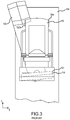
- FIG. 3 is a front elevation of the apparatus of FIG. 2 .
- FIG. 4 is a side view of the apparatus of FIG. 2 with an optional biopsy station.
- FIG. 5 is an enlarged view of an imaging apparatus, with a tube arm assembly in a rotated position.
- FIGS. 6A and 6B depict partial top views of a controller of an imaging apparatus.
- FIG. 7 depicts a top view of an imaging apparatus.
- FIG. 8 depicts a front view of a controller.
- the present technology relates to a breast imaging systems that are used to generate mammograms and/or tomosynthesis images of the breast.
- a technician places a breast of a patient on a platform of an imaging system and compresses the breast against the platform with a breast compression plate or paddle.
- One or more x-ray images are then taken of the breast and processed for analysis.
- FIGS. 1-4 illustrate a non-limiting example of a multi-mode mammography/tomosynthesis system comprising a floor-mounted, upright gantry 100 and a data acquisition work-station 102 .
- Gantry 100 includes a housing 104 supporting a tube arm assembly 106 rotatably mounted thereon to pivot about a horizontal axis 402 ( FIG. 4 ) and carrying an x-ray tube assembly 108 .
- X-ray tube assembly 108 includes (1) an x-ray tube generating x-ray energy in a selected range, such as 20-50 kV, at mAs such as in the range 3-400 mAs, with focal spots such as a nominal size 0.3 mm large spot and nominal size 0.1 mm small spot (2) supports for multiple filters such as molybdenum, rhodium, aluminum, copper, and tin filters, and (3) an adjustable collimation assembly selectively collimating the x-ray beam from the focal spot in a range such as from 7 ⁇ 8 cm to 24 ⁇ 29 when measured at the image plane of an x-ray image receptor included in the system, at a maximum source-image distance such as 75 cm.
- a selected range such as 20-50 kV
- focal spots such as a nominal size 0.3 mm large spot and nominal size 0.1 mm small spot
- supports for multiple filters such as molybdenum, rhodium, aluminum, copper, and tin filters
- an adjustable collimation assembly selectively
- a compression arm assembly 110 that includes a compression device 112 having to a compression plate or paddle 122 and a receptor housing 114 having an upper surface 116 serving as a breast plate and enclosing a receptor subsystem system 117 comprising a flat panel x-ray receptor 119 , a retractable anti-scatter grid 121 , and a mechanism (not shown) for driving and retracting anti-scatter grid 121 .
- Housing 104 also encloses the following components: a vertical travel assembly 404 for moving tube arm assembly 106 and compression arm assembly 110 up and down to accommodate a particular patient or imaging position, a tube arm assembly rotation mechanism 406 to rotate tube arm assembly 106 about axis 402 for different imaging positions, a receptor subsystem rotation mechanism 408 for rotating components of receptor subsystem 117 (such as x-ray receptor 119 ) about axis 402 to accommodate different operation modes, and couple/uncouple mechanism 410 to selectively couple or uncouple tube arm assembly 106 and compression arm assembly 110 to and from each other, and tube arm assembly 106 and receptor subsystem 117 to and from each other. Housing 104 also encloses suitable motors and electrical and mechanical components and connections to implement the functions discussed here.
- a patient shield 125 can be secured to compression arm assembly 110 to provide a mechanical interlock against patient contact with the rotating x-ray tube arm assembly 106 .
- a spacer 1002 ( FIG. 4 ) may be used for different degrees of magnification.
- Work-station 102 comprises components similar to those in the Selenia® Dimensions® mammography system, including a display screen (typically a flat panel display that may include touch-screen functionality), user interface devices such as a keyboard, possibly a touch-screen, and a mouse or trackball, and various switches and indicator lights and/or displays. Work-station 102 also includes computer facilities similar to those of the Selenia® Dimensions® system (but adapted through hardware, firmware and software differences) for controlling gantry 100 and for processing, storing and displaying data received from gantry 100 .
- a power generation facility for x-ray tube assembly 108 may be included in housing 104 or in work-station 102 .
- a power source 118 powers work-station 102 .
- Gantry 100 and work-station 102 exchange data and controls over a schematically illustrated connection 120 .
- the gantry 100 may also include one or more controllers 130 that may be used for certain functions of the gantry 100 .
- the controller 130 is disposed on the compression arm assembly 110 and may be used by a technician to raise or lower the compression arm assembly 110 (e.g., for patients of different heights), raise or lower the compression device 112 , rotate the tube arm assembly 106 , or perform other functions.
- a controller 130 a , 130 b is located on either side of the compression arm assembly 110 , so as to be more easily accessible by a technician. While locating the controller 130 a , 130 b on the compression arm assembly 110 may be convenient for the technician, rotation of the tube arm assembly 106 and/or compression arm assembly 110 may make access thereto difficult, as described below.
- tube arm assembly 106 and compression arm assembly 110 are coupled and locked together by 410 in a relative position such as seen in FIG. 1 , such that an x-ray beam from x-ray tube assembly 108 illuminates x-ray receptor 119 when the patient's breast is compressed by compression device 112 .
- the system operates in a manner similar to said Selenia® Dimensions® system to take a mammogram.
- Vertical travel assembly 404 and tube arm rotation mechanism 406 can make vertical adjustments to accommodate a patient, and can rotate tube arm assembly 106 and compression arm assembly 110 together as a unit about axis 402 for different image orientations such as for CC and for MLO images.
- tube arm assembly 106 and compression arm assembly 110 can rotate between ⁇ 195° and +150° about axis 402 .
- FIG. 4 depicts rotation of the tube arm assembly 106 , which may limit access to the controller 130 b .
- compression device 112 includes a compression paddle 122 that can move laterally, in a direction along the chest wall of a patient, to adjust for different imaging orientations.
- anti-scatter grid 121 is over x-ray receptor 119 in the standard mammography mode to reduce the effect of x-ray scatter.
- both of the tube arm assembly 106 and the compression arm assembly 110 can rotate between ⁇ 195° and +150° about axis 402 .
- FIG. 3 depicts rotation of the tube arm assembly 106 .
- the rotated position of the tube arm assembly 106 may limit technician access to the controller 130 b .
- access may be further limited. For example, if the compression arm assembly 110 rotates counterclockwise from the position depicted in FIG. 3 , the controller 130 a will be extremely difficult to view, let alone activate, especially for technicians that are short of stature. As such, workflow may be impeded if either controller 130 a , 130 b becomes obstructed or otherwise difficult to reach.
- FIG. 5 is an enlarged view of an imaging apparatus 200 , with a tube arm assembly 206 in a rotated position.
- the imaging apparatus 200 may include any or all of the components depicted and described with regard to FIGS. 1-4 . As such, not all of those components are necessarily depicted or described further in the following figures.
- a compression arm assembly 210 and patient shield 225 are also depicted. As in the previous figures, both the tube arm assembly 206 and compression arm assembly 210 may rotate relative to an upright housing 204 (in the form of a pillar having a rectangular, curved, or other shape) of a gantry 201 . Rotation of the tube arm assembly 206 changes a position of the x-ray tube assembly 208 and an enclosed receptor subsystem system 217 .
- Rotation of the compression arm assembly 210 changes a position of a receptor housing 214 and an upper surface 216 thereof, as well as a compression paddle 222 .
- the imaging apparatus 200 of FIG. 5 incorporates a controller 230 a on at least one side of the housing 204 of the upright gantry 201 .
- a second controller may be disposed on an opposite side of the gantry 201 , but is not visible in FIG. 5 .
- the positioning of the controller 230 a in such a location allows a technician to easily access the controller 230 a , regardless of the position of the tube arm assembly 206 , position of the compression arm assembly 210 , height or reach of the technician, etc.
- the controller 230 a may be easily accessed whether the tube arm assembly 206 and compression arm assembly 210 are oriented for a CC or MLO orientation for an examination.
- the controller 230 a may include one or more components required to perform various actions or procedures. Such actions may include but are not limited to, rotation of the tube arm assembly 206 , rotation or elevation change of the compression arm assembly 210 , compression by the paddle 222 to the breast, and so on. Such components may include a graphic user (or touch-sensitive) interface 232 , a button 234 , a knob or dial 236 , a fingerprint scanner 238 (to confirm authorized usage, e.g. or other type of biometric login), or other components. These components are supported in a controller housing 240 that may at least partially protrude from the housing 204 of the gantry 201 . In the example of FIG.
- the controller housing 240 is disposed proximate a slot 242 defined by the housing 204 .
- the controller housing 240 may engage with a projection that extends from an interior of the gantry 201 , through the slot 242 , so as to be slidably moved along the slot 242 . This may further increase the usability of the controller 230 a , for technicians of different heights or reaches, for example. In other examples, however a vertical position of the controller 230 a may be fixed relative to the gantry 201 .
- the controller 230 a In examples where the vertical position of the controller 230 a is fixed, it may be desirable that the controller is disposed at a height H above a floor that is greater than one-half of the total height of the gantry 201 , since technicians of different heights may be able to easily access a controller 230 a so positioned.
- Vertical sides of the controller housing 240 may be longer than top and bottom sides of the controller housing 240 .
- the controller housing 240 may define a longitudinal axis L C that is substantially parallel to a longitudinal axis L G of the gantry 201 .
- Such a longer, narrower controller housing 240 may allow the controller to have a lower profile extending away from the gantry housing 204 . This may prevent the controller 230 a from being inadvertently bumped or contacted as a technician moves about the imaging apparatus 200 .
- Other shapes are contemplated.
- the controller 230 a is depicted as having a rectangular outline. Controllers having circular, oval, D-shaped, or polygonal outlines are also contemplated. Such outlines may be utilized to match the aesthetics of the gantry 201 .
- FIGS. 6A and 6B depict partial top views of a controller 330 a , 330 b of an imaging apparatus 300 a , 300 b .
- the controller 330 a is pivotable P about one or more brackets 350 that extend from a housing 304 a of a gantry 301 a . This allows the controller 330 a to be more easily viewable by a technician working with a patient standing near the front F of the gantry 301 a (e.g., a patient having a breast compressed for imaging).
- a front face 352 b of a controller 330 b is disposed at an angle ⁇ relative to a housing 304 b of a gantry 301 b .
- a first side 354 b has a first length measured from the housing 304 b
- a second side 356 b has a second length measured therefrom. The second length is greater than the first length.
- FIG. 7 depicts a top view of an imaging apparatus 400 , including an upright gantry 401 , a tube arm assembly 406 , and a compression arm assembly 410 .
- a patient P is located at a patient station (e.g., proximate the compression arm assembly 410 where a breast imaging procedure may be performed).
- An axis A extends through a collar 470 that extends from the gantry 401 . Mechanisms within the collar 470 allow for rotation of both the tube arm assembly 406 and the compression arm assembly 410 about the axis A.
- Two controllers 430 a , 430 b are disposed on either side of the gantry 401 .
- each controller 430 a , 430 b face in a direction substantially away from the axis A.
- the front faces 452 a , 452 b are generally out of view of the patient P. This may be advantageous, as flashings lights or other elements on the controllers 430 a , 430 b may cause the patient unnecessary anxiety if visible.
- FIG. 8 depicts a front view of a controller 530 , specifically a substantially D-shaped controller.
- the front face 552 of the controller includes a display screen 532 which may act as a graphic user interface or a simple display.
- the front face 552 also includes a plurality of buttons 534 .
- Certain buttons 534 a may have an outer contour shaped to match an outer perimeter or contour 580 of the controller 530 .
- the controller 530 also includes features that allow a technician to orient herself during use of the controller 530 , without necessarily seeing the front face 552 and the components disposed thereon. Under such circumstances, the controller 530 may be used without being visible to the user.
- the outer perimeter or contour 580 may define one or more recesses or cutouts 582 that, when touched, give an indication to a technician of the location of their hand relative to the front face 552 . In the depicted example, contacting the recess 582 would indicate to the technician that her hand is disposed proximate the display screen 532 .
- a raised feature 584 for example, disposed near or between buttons 534 may also be used to orient a technician to the controller 530 when the controller 530 is not visible.
- the controller 530 may include buttons 534 that are raised, lowered, or flush with the front face 552 , to increase usability thereof.
Landscapes
- Health & Medical Sciences (AREA)
- Life Sciences & Earth Sciences (AREA)
- Engineering & Computer Science (AREA)
- Medical Informatics (AREA)
- Biomedical Technology (AREA)
- Surgery (AREA)
- High Energy & Nuclear Physics (AREA)
- Physics & Mathematics (AREA)
- Nuclear Medicine, Radiotherapy & Molecular Imaging (AREA)
- Optics & Photonics (AREA)
- Pathology (AREA)
- Radiology & Medical Imaging (AREA)
- Veterinary Medicine (AREA)
- Heart & Thoracic Surgery (AREA)
- Molecular Biology (AREA)
- Biophysics (AREA)
- Animal Behavior & Ethology (AREA)
- General Health & Medical Sciences (AREA)
- Public Health (AREA)
- Human Computer Interaction (AREA)
- Dentistry (AREA)
- Oral & Maxillofacial Surgery (AREA)
- Apparatus For Radiation Diagnosis (AREA)
- Pulmonology (AREA)
- Theoretical Computer Science (AREA)
Priority Applications (1)
| Application Number | Priority Date | Filing Date | Title |
|---|---|---|---|
| US16/463,570 US11123030B2 (en) | 2016-11-25 | 2017-11-22 | Controller for imaging apparatus |
Applications Claiming Priority (3)
| Application Number | Priority Date | Filing Date | Title |
|---|---|---|---|
| US201662426349P | 2016-11-25 | 2016-11-25 | |
| US16/463,570 US11123030B2 (en) | 2016-11-25 | 2017-11-22 | Controller for imaging apparatus |
| PCT/US2017/063069 WO2018098321A1 (en) | 2016-11-25 | 2017-11-22 | Controller for imaging apparatus |
Related Parent Applications (1)
| Application Number | Title | Priority Date | Filing Date |
|---|---|---|---|
| PCT/US2017/063069 A-371-Of-International WO2018098321A1 (en) | 2016-11-25 | 2017-11-22 | Controller for imaging apparatus |
Related Child Applications (1)
| Application Number | Title | Priority Date | Filing Date |
|---|---|---|---|
| US17/405,218 Continuation US11684331B2 (en) | 2016-11-25 | 2021-08-18 | Controller for imaging apparatus |
Publications (2)
| Publication Number | Publication Date |
|---|---|
| US20190274650A1 US20190274650A1 (en) | 2019-09-12 |
| US11123030B2 true US11123030B2 (en) | 2021-09-21 |
Family
ID=61005367
Family Applications (3)
| Application Number | Title | Priority Date | Filing Date |
|---|---|---|---|
| US16/463,570 Active US11123030B2 (en) | 2016-11-25 | 2017-11-22 | Controller for imaging apparatus |
| US17/405,218 Active 2038-03-31 US11684331B2 (en) | 2016-11-25 | 2021-08-18 | Controller for imaging apparatus |
| US18/195,991 Active 2038-03-04 US12295764B2 (en) | 2016-11-25 | 2023-05-11 | Controller for imaging apparatus |
Family Applications After (2)
| Application Number | Title | Priority Date | Filing Date |
|---|---|---|---|
| US17/405,218 Active 2038-03-31 US11684331B2 (en) | 2016-11-25 | 2021-08-18 | Controller for imaging apparatus |
| US18/195,991 Active 2038-03-04 US12295764B2 (en) | 2016-11-25 | 2023-05-11 | Controller for imaging apparatus |
Country Status (7)
| Country | Link |
|---|---|
| US (3) | US11123030B2 (enExample) |
| EP (1) | EP3544508A4 (enExample) |
| JP (2) | JP7262388B2 (enExample) |
| CN (1) | CN110139606A (enExample) |
| AU (2) | AU2017363889B2 (enExample) |
| CA (1) | CA3040736A1 (enExample) |
| WO (1) | WO2018098321A1 (enExample) |
Cited By (1)
| Publication number | Priority date | Publication date | Assignee | Title |
|---|---|---|---|---|
| US11684331B2 (en) | 2016-11-25 | 2023-06-27 | Hologic, Inc. | Controller for imaging apparatus |
Families Citing this family (4)
| Publication number | Priority date | Publication date | Assignee | Title |
|---|---|---|---|---|
| DE102017205145A1 (de) * | 2017-03-27 | 2018-09-27 | Siemens Healthcare Gmbh | Gehäusevorrichtung mit einer Benutzerschnittstelle sowie eine medizinische Bildgebungsvorrichtung mit der Gehäusevorrichtung |
| US10863952B2 (en) * | 2018-06-21 | 2020-12-15 | General Electric Company | Apparatus, system and method for controlling medical equipment |
| US12011305B2 (en) | 2018-09-24 | 2024-06-18 | Hologic, Inc. | Multi-screen imaging system for improved workflow |
| CN113208640B (zh) * | 2021-04-26 | 2023-05-30 | 复旦大学附属肿瘤医院 | 一种基于乳腺专用pet影像组学预测腋窝淋巴结转移的方法 |
Citations (8)
| Publication number | Priority date | Publication date | Assignee | Title |
|---|---|---|---|---|
| EP0775467A1 (en) | 1995-11-23 | 1997-05-28 | Planmed Oy | Method and system for controlling the functions of a mammography apparatus |
| US20050129172A1 (en) | 2003-11-17 | 2005-06-16 | Thomas Mertelmeier | X-ray diagnostic apparatus for mammography examinations |
| US20090304159A1 (en) | 2006-02-03 | 2009-12-10 | Oliver Meer | Positioning device for a mammography unit |
| US20110021947A1 (en) | 2009-07-24 | 2011-01-27 | Fujifilm Corporation | Radiographic image capturing apparatus |
| US20130331682A1 (en) | 2011-02-25 | 2013-12-12 | Fujifilm Corporation | Breast image capturing apparatus |
| EP2727534A1 (en) | 2011-07-01 | 2014-05-07 | Rayence Co., Ltd. | Mammography detector having multiple sensors, and mammography device capable of 3d image acquisition |
| US20150049859A1 (en) | 2004-11-26 | 2015-02-19 | Hologic, Inc. | Integrated multi-mode mammography/tomosynthesis x-ray system and method |
| KR20160091958A (ko) | 2013-11-29 | 2016-08-03 | 플란메드 오와이 | 유방촬영 기기 |
Family Cites Families (10)
| Publication number | Priority date | Publication date | Assignee | Title |
|---|---|---|---|---|
| FI120077B (fi) * | 2007-11-14 | 2009-06-30 | Planmed Oy | Järjestely ja menetelmä digitaalisessa mammografiakuvauksessa |
| JP2010005157A (ja) * | 2008-06-27 | 2010-01-14 | Fujifilm Corp | 放射線画像撮影装置およびその制御方法 |
| WO2010028208A1 (en) | 2008-09-04 | 2010-03-11 | Hologic, Inc. | Integrated multi-mode mammography/tomosynthesis x-ray system and method |
| JP2010110571A (ja) | 2008-11-10 | 2010-05-20 | Fujifilm Corp | 撮影装置及びマンモグラフィ装置 |
| JP5709820B2 (ja) * | 2012-11-08 | 2015-04-30 | 株式会社モリタ製作所 | X線撮影装置 |
| JP2013066784A (ja) | 2013-01-22 | 2013-04-18 | Toshiba Corp | 乳房撮影検査用x線診断装置 |
| KR101507809B1 (ko) * | 2013-05-02 | 2015-04-07 | 삼성전자주식회사 | 의료 기기용 사용자 제어 장치 및 이를 포함하는 의료 기기 |
| FI126329B (fi) * | 2013-11-29 | 2016-10-14 | Planmed Oy | Mammografialaitejärjestely |
| CN105982684A (zh) * | 2015-02-26 | 2016-10-05 | 上海西门子医疗器械有限公司 | X射线设备和x射线设备的控制方法、控制台 |
| JP7262388B2 (ja) | 2016-11-25 | 2023-04-21 | ホロジック, インコーポレイテッド | 撮像装置のためのコントローラ |
-
2017
- 2017-11-22 JP JP2019527193A patent/JP7262388B2/ja active Active
- 2017-11-22 CA CA3040736A patent/CA3040736A1/en active Pending
- 2017-11-22 AU AU2017363889A patent/AU2017363889B2/en active Active
- 2017-11-22 WO PCT/US2017/063069 patent/WO2018098321A1/en not_active Ceased
- 2017-11-22 EP EP17873420.8A patent/EP3544508A4/en active Pending
- 2017-11-22 US US16/463,570 patent/US11123030B2/en active Active
- 2017-11-22 CN CN201780072716.4A patent/CN110139606A/zh active Pending
- 2017-11-24 AU AU2017101644A patent/AU2017101644A4/en not_active Expired
-
2021
- 2021-08-18 US US17/405,218 patent/US11684331B2/en active Active
-
2022
- 2022-10-11 JP JP2022163047A patent/JP2022188242A/ja active Pending
-
2023
- 2023-05-11 US US18/195,991 patent/US12295764B2/en active Active
Patent Citations (9)
| Publication number | Priority date | Publication date | Assignee | Title |
|---|---|---|---|---|
| EP0775467A1 (en) | 1995-11-23 | 1997-05-28 | Planmed Oy | Method and system for controlling the functions of a mammography apparatus |
| US20050129172A1 (en) | 2003-11-17 | 2005-06-16 | Thomas Mertelmeier | X-ray diagnostic apparatus for mammography examinations |
| US20150049859A1 (en) | 2004-11-26 | 2015-02-19 | Hologic, Inc. | Integrated multi-mode mammography/tomosynthesis x-ray system and method |
| US20090304159A1 (en) | 2006-02-03 | 2009-12-10 | Oliver Meer | Positioning device for a mammography unit |
| US20110021947A1 (en) | 2009-07-24 | 2011-01-27 | Fujifilm Corporation | Radiographic image capturing apparatus |
| US20130331682A1 (en) | 2011-02-25 | 2013-12-12 | Fujifilm Corporation | Breast image capturing apparatus |
| EP2727534A1 (en) | 2011-07-01 | 2014-05-07 | Rayence Co., Ltd. | Mammography detector having multiple sensors, and mammography device capable of 3d image acquisition |
| KR20160091958A (ko) | 2013-11-29 | 2016-08-03 | 플란메드 오와이 | 유방촬영 기기 |
| US20170020471A1 (en) * | 2013-11-29 | 2017-01-26 | Planmed Oy | Mammography apparatus |
Non-Patent Citations (3)
| Title |
|---|
| European extended Search Report in Application EP 17873420.8, dated Jun. 25, 2020, 6 pages. |
| International Search Report and Written Opinion of the International Searching Authority for International Patent Application No. PCT/US2017/063069 dated Feb. 9, 2018, 13 pages. |
| PCT International Preliminary Report on Patentability in Application PCT/US2017/063069, dated Jun. 6, 2019, 8 pages. |
Cited By (2)
| Publication number | Priority date | Publication date | Assignee | Title |
|---|---|---|---|---|
| US11684331B2 (en) | 2016-11-25 | 2023-06-27 | Hologic, Inc. | Controller for imaging apparatus |
| US12295764B2 (en) | 2016-11-25 | 2025-05-13 | Hologic, Inc. | Controller for imaging apparatus |
Also Published As
| Publication number | Publication date |
|---|---|
| EP3544508A1 (en) | 2019-10-02 |
| CA3040736A1 (en) | 2018-05-31 |
| AU2017101644A4 (en) | 2018-01-18 |
| EP3544508A4 (en) | 2020-07-29 |
| AU2017363889B2 (en) | 2023-06-08 |
| US20190274650A1 (en) | 2019-09-12 |
| US11684331B2 (en) | 2023-06-27 |
| AU2017363889A1 (en) | 2019-05-02 |
| CN110139606A (zh) | 2019-08-16 |
| WO2018098321A1 (en) | 2018-05-31 |
| JP2022188242A (ja) | 2022-12-20 |
| JP2019535420A (ja) | 2019-12-12 |
| JP7262388B2 (ja) | 2023-04-21 |
| US20220022823A1 (en) | 2022-01-27 |
| US12295764B2 (en) | 2025-05-13 |
| US20230346327A1 (en) | 2023-11-02 |
Similar Documents
| Publication | Publication Date | Title |
|---|---|---|
| US12295764B2 (en) | Controller for imaging apparatus | |
| US12064291B2 (en) | Tomosynthesis-guided biopsy in prone | |
| US11617548B2 (en) | Integrated multi-mode mammography/tomosynthesis x-ray system and method | |
| EP2326248B1 (en) | Integrated multi-mode mammography/tomosynthesis x-ray system | |
| US10603002B2 (en) | Pivoting paddle apparatus for mammography/tomosynthesis X-ray system | |
| US7835490B2 (en) | Mammography appliance | |
| US12059282B2 (en) | Medical imaging system with contoured detector |
Legal Events
| Date | Code | Title | Description |
|---|---|---|---|
| FEPP | Fee payment procedure |
Free format text: ENTITY STATUS SET TO UNDISCOUNTED (ORIGINAL EVENT CODE: BIG.); ENTITY STATUS OF PATENT OWNER: LARGE ENTITY |
|
| STPP | Information on status: patent application and granting procedure in general |
Free format text: DOCKETED NEW CASE - READY FOR EXAMINATION |
|
| AS | Assignment |
Owner name: BANK OF AMERICA, N.A., AS COLLATERAL AGENT, NORTH CAROLINA Free format text: SECURITY INTEREST;ASSIGNORS:HOLOGIC, INC.;CYNOSURE, LLC;CYTYC CORPORATION;AND OTHERS;REEL/FRAME:050719/0701 Effective date: 20191011 Owner name: BANK OF AMERICA, N.A., AS COLLATERAL AGENT, NORTH Free format text: SECURITY INTEREST;ASSIGNORS:HOLOGIC, INC.;CYNOSURE, LLC;CYTYC CORPORATION;AND OTHERS;REEL/FRAME:050719/0701 Effective date: 20191011 |
|
| STPP | Information on status: patent application and granting procedure in general |
Free format text: RESPONSE AFTER FINAL ACTION FORWARDED TO EXAMINER |
|
| STPP | Information on status: patent application and granting procedure in general |
Free format text: ADVISORY ACTION MAILED |
|
| STPP | Information on status: patent application and granting procedure in general |
Free format text: DOCKETED NEW CASE - READY FOR EXAMINATION |
|
| STPP | Information on status: patent application and granting procedure in general |
Free format text: NOTICE OF ALLOWANCE MAILED -- APPLICATION RECEIVED IN OFFICE OF PUBLICATIONS |
|
| AS | Assignment |
Owner name: HOLOGIC, INC., MASSACHUSETTS Free format text: ASSIGNMENT OF ASSIGNORS INTEREST;ASSIGNORS:HISATA, SUZUKO;BERKO, MALLORY ANNE;GIRGENTI, JONATHAN PAUL;AND OTHERS;SIGNING DATES FROM 20190528 TO 20190603;REEL/FRAME:056291/0231 |
|
| STPP | Information on status: patent application and granting procedure in general |
Free format text: PUBLICATIONS -- ISSUE FEE PAYMENT VERIFIED |
|
| STCF | Information on status: patent grant |
Free format text: PATENTED CASE |
|
| AS | Assignment |
Owner name: BANK OF AMERICA, N.A., AS COLLATERAL AGENT, NORTH CAROLINA Free format text: SECURITY INTEREST;ASSIGNORS:HOLOGIC, INC.;FAXITRON BIOPTICS, LLC;BIOTHERANOSTICS, INC.;AND OTHERS;REEL/FRAME:057787/0526 Effective date: 20211007 |
|
| MAFP | Maintenance fee payment |
Free format text: PAYMENT OF MAINTENANCE FEE, 4TH YEAR, LARGE ENTITY (ORIGINAL EVENT CODE: M1551); ENTITY STATUS OF PATENT OWNER: LARGE ENTITY Year of fee payment: 4 |