US11095189B2 - Driving mechanism - Google Patents
Driving mechanism Download PDFInfo
- Publication number
- US11095189B2 US11095189B2 US16/415,965 US201916415965A US11095189B2 US 11095189 B2 US11095189 B2 US 11095189B2 US 201916415965 A US201916415965 A US 201916415965A US 11095189 B2 US11095189 B2 US 11095189B2
- Authority
- US
- United States
- Prior art keywords
- driving
- driving mechanism
- mechanism according
- motor assembly
- controller
- Prior art date
- Legal status (The legal status is an assumption and is not a legal conclusion. Google has not performed a legal analysis and makes no representation as to the accuracy of the status listed.)
- Active, expires
Links
Images


Classifications
-
- B—PERFORMING OPERATIONS; TRANSPORTING
- B62—LAND VEHICLES FOR TRAVELLING OTHERWISE THAN ON RAILS
- B62M—RIDER PROPULSION OF WHEELED VEHICLES OR SLEDGES; POWERED PROPULSION OF SLEDGES OR SINGLE-TRACK CYCLES; TRANSMISSIONS SPECIALLY ADAPTED FOR SUCH VEHICLES
- B62M7/00—Motorcycles characterised by position of motor or engine
- B62M7/12—Motorcycles characterised by position of motor or engine with the engine beside or within the driven wheel
-
- H—ELECTRICITY
- H02—GENERATION; CONVERSION OR DISTRIBUTION OF ELECTRIC POWER
- H02K—DYNAMO-ELECTRIC MACHINES
- H02K7/00—Arrangements for handling mechanical energy structurally associated with dynamo-electric machines, e.g. structural association with mechanical driving motors or auxiliary dynamo-electric machines
- H02K7/006—Structural association of a motor or generator with the drive train of a motor vehicle
-
- B—PERFORMING OPERATIONS; TRANSPORTING
- B62—LAND VEHICLES FOR TRAVELLING OTHERWISE THAN ON RAILS
- B62J—CYCLE SADDLES OR SEATS; AUXILIARY DEVICES OR ACCESSORIES SPECIALLY ADAPTED TO CYCLES AND NOT OTHERWISE PROVIDED FOR, e.g. ARTICLE CARRIERS OR CYCLE PROTECTORS
- B62J50/00—Arrangements specially adapted for use on cycles not provided for in main groups B62J1/00 - B62J45/00
- B62J50/30—Means for ventilation within devices provided on the cycle, e.g. ventilation means in a battery container
-
- B—PERFORMING OPERATIONS; TRANSPORTING
- B62—LAND VEHICLES FOR TRAVELLING OTHERWISE THAN ON RAILS
- B62K—CYCLES; CYCLE FRAMES; CYCLE STEERING DEVICES; RIDER-OPERATED TERMINAL CONTROLS SPECIALLY ADAPTED FOR CYCLES; CYCLE AXLE SUSPENSIONS; CYCLE SIDE-CARS, FORECARS, OR THE LIKE
- B62K11/00—Motorcycles, engine-assisted cycles or motor scooters with one or two wheels
-
- B—PERFORMING OPERATIONS; TRANSPORTING
- B62—LAND VEHICLES FOR TRAVELLING OTHERWISE THAN ON RAILS
- B62K—CYCLES; CYCLE FRAMES; CYCLE STEERING DEVICES; RIDER-OPERATED TERMINAL CONTROLS SPECIALLY ADAPTED FOR CYCLES; CYCLE AXLE SUSPENSIONS; CYCLE SIDE-CARS, FORECARS, OR THE LIKE
- B62K25/00—Axle suspensions
- B62K25/04—Axle suspensions for mounting axles resiliently on cycle frame or fork
- B62K25/28—Axle suspensions for mounting axles resiliently on cycle frame or fork with pivoted chain-stay
- B62K25/283—Axle suspensions for mounting axles resiliently on cycle frame or fork with pivoted chain-stay for cycles without a pedal crank, e.g. motorcycles
-
- B—PERFORMING OPERATIONS; TRANSPORTING
- B62—LAND VEHICLES FOR TRAVELLING OTHERWISE THAN ON RAILS
- B62M—RIDER PROPULSION OF WHEELED VEHICLES OR SLEDGES; POWERED PROPULSION OF SLEDGES OR SINGLE-TRACK CYCLES; TRANSMISSIONS SPECIALLY ADAPTED FOR SUCH VEHICLES
- B62M6/00—Rider propulsion of wheeled vehicles with additional source of power, e.g. combustion engine or electric motor
- B62M6/40—Rider propelled cycles with auxiliary electric motor
- B62M6/60—Rider propelled cycles with auxiliary electric motor power-driven at axle parts
-
- H—ELECTRICITY
- H02—GENERATION; CONVERSION OR DISTRIBUTION OF ELECTRIC POWER
- H02K—DYNAMO-ELECTRIC MACHINES
- H02K11/00—Structural association of dynamo-electric machines with electric components or with devices for shielding, monitoring or protection
- H02K11/30—Structural association with control circuits or drive circuits
- H02K11/33—Drive circuits, e.g. power electronics
-
- H—ELECTRICITY
- H02—GENERATION; CONVERSION OR DISTRIBUTION OF ELECTRIC POWER
- H02K—DYNAMO-ELECTRIC MACHINES
- H02K5/00—Casings; Enclosures; Supports
- H02K5/04—Casings or enclosures characterised by the shape, form or construction thereof
- H02K5/10—Casings or enclosures characterised by the shape, form or construction thereof with arrangements for protection from ingress, e.g. water or fingers
-
- H—ELECTRICITY
- H02—GENERATION; CONVERSION OR DISTRIBUTION OF ELECTRIC POWER
- H02K—DYNAMO-ELECTRIC MACHINES
- H02K5/00—Casings; Enclosures; Supports
- H02K5/04—Casings or enclosures characterised by the shape, form or construction thereof
- H02K5/18—Casings or enclosures characterised by the shape, form or construction thereof with ribs or fins for improving heat transfer
-
- H—ELECTRICITY
- H02—GENERATION; CONVERSION OR DISTRIBUTION OF ELECTRIC POWER
- H02K—DYNAMO-ELECTRIC MACHINES
- H02K5/00—Casings; Enclosures; Supports
- H02K5/04—Casings or enclosures characterised by the shape, form or construction thereof
- H02K5/22—Auxiliary parts of casings not covered by groups H02K5/06-H02K5/20, e.g. shaped to form connection boxes or terminal boxes
- H02K5/225—Terminal boxes or connection arrangements
-
- H—ELECTRICITY
- H02—GENERATION; CONVERSION OR DISTRIBUTION OF ELECTRIC POWER
- H02K—DYNAMO-ELECTRIC MACHINES
- H02K7/00—Arrangements for handling mechanical energy structurally associated with dynamo-electric machines, e.g. structural association with mechanical driving motors or auxiliary dynamo-electric machines
- H02K7/10—Structural association with clutches, brakes, gears, pulleys or mechanical starters
- H02K7/116—Structural association with clutches, brakes, gears, pulleys or mechanical starters with gears
-
- H—ELECTRICITY
- H02—GENERATION; CONVERSION OR DISTRIBUTION OF ELECTRIC POWER
- H02K—DYNAMO-ELECTRIC MACHINES
- H02K9/00—Arrangements for cooling or ventilating
- H02K9/22—Arrangements for cooling or ventilating by solid heat conducting material embedded in, or arranged in contact with, the stator or rotor, e.g. heat bridges
- H02K9/227—Heat sinks
-
- B—PERFORMING OPERATIONS; TRANSPORTING
- B62—LAND VEHICLES FOR TRAVELLING OTHERWISE THAN ON RAILS
- B62K—CYCLES; CYCLE FRAMES; CYCLE STEERING DEVICES; RIDER-OPERATED TERMINAL CONTROLS SPECIALLY ADAPTED FOR CYCLES; CYCLE AXLE SUSPENSIONS; CYCLE SIDE-CARS, FORECARS, OR THE LIKE
- B62K2204/00—Adaptations for driving cycles by electric motor
-
- H—ELECTRICITY
- H02—GENERATION; CONVERSION OR DISTRIBUTION OF ELECTRIC POWER
- H02K—DYNAMO-ELECTRIC MACHINES
- H02K2211/00—Specific aspects not provided for in the other groups of this subclass relating to measuring or protective devices or electric components
- H02K2211/03—Machines characterised by circuit boards, e.g. pcb
Definitions
- the present disclosure relates to a driving mechanism, and more particularly to a driving mechanism for electric motorcycle.
- a swing arm is installed between the frame and the driving wheel in currently motorcycle structure. While applied in the electric motorcycle, the electric motor and the driving controller are installed on both sides of the swing arm respectively.
- the battery provides the power
- the driving controller is electrically connected to the motor for controlling the operation and the signal feedback.
- fixing interface and structure should be installed additionally. Accordingly, the assembly volume becomes larger, the difficulty of assembling becomes higher, and the cost of time becomes longer.
- the exposed wires between the motor and the driving controller e.g., power cords and signal wires
- the air tightness and the waterproofness are poor, and the risk of bending or damaging the wire is increased.
- An object of the present disclosure provides a driving mechanism.
- the driving mechanism is assembled between the frame and the driving wheel for replacing the conventional swing arm as an assisted support structure.
- the unsprung weight of the motorcycle with the driving mechanism is lighter, which improves the maneuverability and handling performance.
- the motor assembly and the driving controller are both accommodated in the inner space of the motor housing. Consequently, the air tightness and waterproofness are improved, the length of the wires connected between the motor assembly and the driving controller is dramatically shortened, and the assembling time and unnecessary waterproof interface and connector are all saved.
- a plurality of wires connected between the motor assembly and the driving controller are all accommodated in the inner space of the motor housing. Accordingly, the wires are protected from being exposed, bent and damaged, thus the cost of wire maintenance is reduced, and the electrical reliability is improved.
- a driving mechanism connects with a frame and a driving wheel by two ends thereof.
- the driving mechanism includes a motor housing, a motor assembly and a driving controller.
- the motor housing supports the frame and defines an inner space.
- the motor assembly is detachably assembled with the motor housing and located in the inner space.
- the motor assembly drives the driving wheel.
- the driving controller is detachably assembled with the motor housing, located in the inner space, and electrically connected with the motor assembly.
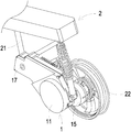
- FIG. 1 is a partial schematic perspective view illustrating a driving mechanism of the present disclosure assembled with a motorcycle
- FIG. 2A is a schematic perspective view illustrating the driving mechanism according to an embodiment of the present disclosure
- FIG. 2B is a schematic perspective view illustrating the driving mechanism of FIG. 2A at another viewing angle
- FIG. 3A is an exploded view showing the driving mechanism of FIG. 2A ;
- FIG. 3B is an exploded view showing the driving mechanism of FIG. 2A at another viewing angle.
- FIG. 1 is a partial schematic perspective view illustrating a driving mechanism of the present disclosure assembled with a motorcycle.
- FIG. 2A and FIG. 2B are schematic perspective views illustrating the driving mechanism according to an embodiment of the present disclosure at different viewing angles.
- FIG. 3A and FIG. 3B are exploded views showing the driving mechanism of FIG. 2A at different viewing angles. Please refer to FIGS. 1, 2A, 2B, 3A and 3B .
- Two ends of a driving mechanism 1 of the present disclosure are assembled and connected with a frame 21 and a driving wheel 22 of a motorcycle 2 respectively.
- the driving mechanism 1 is configured to drive the motorcycle 2 and support the frame 21 as an assistant structure.
- there still have common shock absorber (damper) and spring as the design of main support structures.
- the driving mechanism 1 of the present disclosure includes a motor housing 11 , a motor assembly 12 and a driving controller 13 . It should be noted that the driving mechanism 1 in this embodiment can also be adapted to drive a bicycle using an electric motor, but is not limited thereto.
- the motor housing 11 defines and forms an inner space 111 .
- the motor housing 11 includes at least one top cover 112 and at least one bottom cover 113 .
- the top cover 112 and the bottom cover 113 are detachably assembled with each other to define and form the inner space 111 .
- the bottom cover 113 is located between the top cover 112 and the frame 21 , or is located between the top cover 112 and the driving wheel 22 .
- the motor assembly 12 is detachably assembled with the motor housing 11 , located in the inner space 111 , and configured for driving the driving wheel 22 .
- the motor assembly 12 includes a rotor 121 and a stator 122 .
- the rotor 121 is combined with the stator 122 and is capable of rotating relative to the stator 122 .
- the motor assembly 12 is detachably assembled with the corresponding bottom cover 113 .
- the driving controller 13 is detachably assembled with the motor housing 11 and is located in the inner space 111 .
- the driving controller 13 is electrically connected with the motor assembly 12 through a plurality of wires (not shown).
- the motor assembly 12 and the driving controller 13 are electrically connected with each other through a terminal block or a patch board 14 .
- the plurality of wires e.g., power cords and signal wires
- the plurality of wires e.g., power cords and signal wires
- the driving mechanism 1 further includes a reducer mechanism 15 .
- the reducer mechanism 15 is assembled with the motor assembly 12 and the driving wheel 22 , or the reducer mechanism 15 is integrated with the driving wheel 22 and then assembled with the motor assembly 12 . Therefore, the motor assembly 12 can drive the driving wheel 22 of the motorcycle 2 through the reducer mechanism 15 .
- the driving wheel 22 referred in the industry is the wheel capable of driving vehicles, and transmitting and outputting the power from a motor, and the driving wheel 22 is usually the back wheel, but not limited thereto.
- the driving mechanism 1 Since the driving mechanism 1 is assembled and connected with the frame 21 and the driving wheel 22 , the driving mechanism 1 can replace the swing arm of conventional motorcycle as an auxiliary support structure of the frame 21 . Compared with the conventional motorcycle with swing arm, the motorcycle with the driving mechanism 1 of the present disclosure omits partial components. Thus, the unsprung weight of the motorcycle 2 drived by the driving mechanism 1 is relatively lighter, which improves the maneuverability and handling performance.
- the motor assembly 12 , the driving controller 13 and the wires for connection are all accommodated in the inner space 111 of the motor housing 11 , rather than the exposed structure as of traditional design.
- the air tightness and waterproofness are improved, the system is ensured to be stable, and the length of the wires connected between the motor assembly 12 and the driving controller 13 is dramatically shortened. Consequently, the assembling time, the unnecessary wires, and the cost for unnecessary waterproof interface and connector are all saved.
- the plurality of wires connected with the motor assembly 12 , the driving controller 13 and connected therebetween are all accommodated in the inner space 111 . Therefore, the wires are protected from being exposed, bent and damaged, thus the wire maintenance cost is reduced, and the electrical reliability is improved.
- the driving controller 13 is detachably assembled with the top cover 112 .
- the driving controller 13 is detachably assembled with the bottom cover 113 .
- the motor assembly 12 may be integrated with the top cover 112 or the bottom cover 113 of the motor housing 11 . Assembling interfaces and structures of the top cover 112 or the bottom cover 113 of the motor housing 11 are designed for requirements correspondingly to make the structures and contours thereof match up. Consequently, the utilization rate of space is improved, and the complexity of assembly is decreased. It is noted that design of the motor assembly 12 of the present disclosure is not limited thereto.
- the number of the top cover 112 and the bottom cover 113 of the motor housing 11 are without restriction, and it can be adjusted according to practical requirements.
- the motor housing 11 includes one top cover 112 and one bottom cover 113 , and the motor assembly 12 and the driving controller 13 share the bottom cover 113 .
- the top cover 112 includes one first covering plate 112 a and one second covering plate 112 b .
- the first covering plate 112 a of the top cover 112 is configured to cover the motor assembly 12
- the second covering plate 112 b of the top cover 112 is configured to cover the driving controller 13 , but not limited thereto.
- the motor assembly 12 and the driving controller 13 may share or be collectively assembled to a same covering plate.
- the second covering plate 112 b of the top cover 112 may further includes a movable covering plate 112 c .
- the movable covering plate 112 c is detachably disposed corresponding to the location(s) of the terminal block, the patch board 14 and/or at least a part of the driving controller 13 .
- the wires and/or the driving controller 13 need to be maintained or replaced, it is convenient since the operator only have to remove the movable covering plate 112 c , rather than the second covering plate 112 b of the top cover 112 .
- the motor housing 11 includes at least one set of heat sink 114 .
- the heat sink 114 is integrated with the top cover 112 and/or the bottom cover 113 of the motor housing 11 .
- the driving mechanism 1 further includes a heat dissipating plate 16 .
- the heat dissipating plate 16 is located in the inner space 111 of the motor housing 11 , i.e., inside of the motor housing 11 , and is connected or attached to the driving controller 13 therein for providing the driving controller 13 with direct heat dissipation.
- the heat dissipating plate 16 and the driving controller 13 may be modularized to form a structures, and the modularized structures are detachably assembled with the top cover 112 or the bottom cover 113 of the motor housing 11 collectively.
- the driving mechanism 1 further includes a first fixing hole 17 and a second fixing hole 18 .
- the first fixing hole 17 is configured for assembling the driving mechanism 1 with the frame 21 of the motorcycle 2 .
- the second fixing hole 18 is configured for assembling the driving mechanism 1 with the driving wheel 22 of the motorcycle 2 and assembling the reduce mechanism 15 with the motor assembly 12 .
- the motor housing 11 further includes a wiring hole 115 .
- the wiring hole 115 is in communication with the inner space 111 of the motor housing 11 , and is configured for the wires to penetrate therethrough. For example, the wires connected between the driving controller 13 and the motor assembly 12 penetrates through the wiring hole 115 , but not limited thereto.
- the present disclosure provides a driving mechanism.
- the driving mechanism is assembled and connected with the frame and the driving wheel for replacing the conventional swing arm as an assisted support structure.
- the unsprung weight of the motorcycle with the driving mechanism is lighter, which improves the maneuverability and handling performance.
- the motor assembly, the driving controller and the wires for connection are all accommodated in the inner space of the motor housing. Accordingly, the air tightness and waterproofness are improved, the system is ensured to be stable, and the length and amount of the wires connected between the motor assembly and the driving controller are dramatically reduced. Consequently, the assembling time and the cost for unnecessary waterproof interface and connector are all saved.
- the plurality of wires connected with the motor assembly and the driving controller and connected therebetween are all accommodated in the inner space of the motor housing. Therefore, the wires are protected from being exposed, bent and damaged, thus the wire maintenance cost is reduced, and the electrical reliability is improved.
- the motor assembly and the driving controller may be integrated with the motor housing, thus the utilization rate of space is improved, and the complexity of assembly is decreased.
- the heat sink is disposed on the motor housing, or the heat dissipating plate is disposed in the inner space. Therefore, the efficiency of heat dissipation is improved.
Applications Claiming Priority (2)
| Application Number | Priority Date | Filing Date | Title |
|---|---|---|---|
| CN201811624523.8A CN111377033B (zh) | 2018-12-28 | 2018-12-28 | 驱动机构 |
| CN201811624523.8 | 2018-12-28 |
Publications (2)
| Publication Number | Publication Date |
|---|---|
| US20200212759A1 US20200212759A1 (en) | 2020-07-02 |
| US11095189B2 true US11095189B2 (en) | 2021-08-17 |
Family
ID=71124290
Family Applications (1)
| Application Number | Title | Priority Date | Filing Date |
|---|---|---|---|
| US16/415,965 Active 2039-07-18 US11095189B2 (en) | 2018-12-28 | 2019-05-17 | Driving mechanism |
Country Status (3)
| Country | Link |
|---|---|
| US (1) | US11095189B2 (zh) |
| CN (1) | CN111377033B (zh) |
| WO (1) | WO2020134237A1 (zh) |
Families Citing this family (3)
| Publication number | Priority date | Publication date | Assignee | Title |
|---|---|---|---|---|
| US11396340B2 (en) * | 2020-03-05 | 2022-07-26 | Horizon Trade Group Llc | Two wheel electric motorized cycle frame incorporating a case-free battery |
| CN114919689B (zh) * | 2021-10-08 | 2023-07-14 | 江门市珠峰摩托车有限公司 | 一种电动摩托车侧挂动力控制系统 |
| CN115320773A (zh) * | 2022-07-27 | 2022-11-11 | 浙江乐骑机车有限公司 | 一种集成式动力总成 |
Citations (12)
| Publication number | Priority date | Publication date | Assignee | Title |
|---|---|---|---|---|
| US20040238253A1 (en) * | 2003-05-30 | 2004-12-02 | Atsushi Yonehana | Under-seat structure for a motorcycle |
| CN101712355A (zh) | 2008-09-30 | 2010-05-26 | 本田技研工业株式会社 | 电动二轮车 |
| US20110139531A1 (en) * | 2008-09-30 | 2011-06-16 | Yoshihisa Kanno | Electric motorcycle |
| TW201238834A (en) | 2011-01-13 | 2012-10-01 | Honda Motor Co Ltd | Electric vehicle |
| JP2013129338A (ja) | 2011-12-22 | 2013-07-04 | Yamaha Motor Co Ltd | 鞍乗型電動車両のパワーユニット及び鞍乗型電動車両 |
| DE102012207775A1 (de) | 2012-05-10 | 2013-11-14 | Schaeffler Technologies AG & Co. KG | Elektrisch angetriebenes Zweirad |
| CN103963907A (zh) | 2013-01-25 | 2014-08-06 | 姚立和 | 自行车电动装置 |
| TW201504109A (zh) | 2013-07-19 | 2015-02-01 | Kwang Yang Motor Co | 電動機車 |
| US20160254719A1 (en) * | 2015-02-27 | 2016-09-01 | Brose Fahrzeugteile Gmbh & Co. Kommanditgesellschaft, Wuerzburg | Motor assembly |
| CN205737954U (zh) * | 2016-06-17 | 2016-11-30 | 重庆力华科技有限责任公司 | 一体式两轮电动车侧挂动力机构 |
| CN107651097A (zh) | 2017-09-25 | 2018-02-02 | 浙江雅迪机车有限公司 | 一种电动车的侧挂电机 |
| CN108883802A (zh) | 2016-03-31 | 2018-11-23 | 本田技研工业株式会社 | 电动车辆的驱动装置 |
Family Cites Families (3)
| Publication number | Priority date | Publication date | Assignee | Title |
|---|---|---|---|---|
| JP6193304B2 (ja) * | 2015-05-29 | 2017-09-06 | ヤマハ発動機株式会社 | 鞍乗型電動車両 |
| JP6661968B2 (ja) * | 2015-10-27 | 2020-03-11 | スズキ株式会社 | 電動二輪車の水抜き構造 |
| CN207482120U (zh) * | 2017-10-18 | 2018-06-12 | 杨键亿 | 电动车的电控与马达冷却装置 |
-
2018
- 2018-12-28 CN CN201811624523.8A patent/CN111377033B/zh active Active
-
2019
- 2019-05-17 US US16/415,965 patent/US11095189B2/en active Active
- 2019-09-24 WO PCT/CN2019/107558 patent/WO2020134237A1/zh active Application Filing
Patent Citations (12)
| Publication number | Priority date | Publication date | Assignee | Title |
|---|---|---|---|---|
| US20040238253A1 (en) * | 2003-05-30 | 2004-12-02 | Atsushi Yonehana | Under-seat structure for a motorcycle |
| CN101712355A (zh) | 2008-09-30 | 2010-05-26 | 本田技研工业株式会社 | 电动二轮车 |
| US20110139531A1 (en) * | 2008-09-30 | 2011-06-16 | Yoshihisa Kanno | Electric motorcycle |
| TW201238834A (en) | 2011-01-13 | 2012-10-01 | Honda Motor Co Ltd | Electric vehicle |
| JP2013129338A (ja) | 2011-12-22 | 2013-07-04 | Yamaha Motor Co Ltd | 鞍乗型電動車両のパワーユニット及び鞍乗型電動車両 |
| DE102012207775A1 (de) | 2012-05-10 | 2013-11-14 | Schaeffler Technologies AG & Co. KG | Elektrisch angetriebenes Zweirad |
| CN103963907A (zh) | 2013-01-25 | 2014-08-06 | 姚立和 | 自行车电动装置 |
| TW201504109A (zh) | 2013-07-19 | 2015-02-01 | Kwang Yang Motor Co | 電動機車 |
| US20160254719A1 (en) * | 2015-02-27 | 2016-09-01 | Brose Fahrzeugteile Gmbh & Co. Kommanditgesellschaft, Wuerzburg | Motor assembly |
| CN108883802A (zh) | 2016-03-31 | 2018-11-23 | 本田技研工业株式会社 | 电动车辆的驱动装置 |
| CN205737954U (zh) * | 2016-06-17 | 2016-11-30 | 重庆力华科技有限责任公司 | 一体式两轮电动车侧挂动力机构 |
| CN107651097A (zh) | 2017-09-25 | 2018-02-02 | 浙江雅迪机车有限公司 | 一种电动车的侧挂电机 |
Also Published As
| Publication number | Publication date |
|---|---|
| WO2020134237A1 (zh) | 2020-07-02 |
| CN111377033A (zh) | 2020-07-07 |
| US20200212759A1 (en) | 2020-07-02 |
| CN111377033B (zh) | 2021-10-01 |
Similar Documents
| Publication | Publication Date | Title |
|---|---|---|
| US11095189B2 (en) | Driving mechanism | |
| JP4619992B2 (ja) | 電気接続箱 | |
| US20150211698A1 (en) | Light bar structure, light source module and lamp | |
| US8614890B2 (en) | Chassis extension module | |
| JP2013097946A (ja) | インバータとモータ内蔵ドライブトレインとの電気的接続構造 | |
| US10389214B2 (en) | Motor and producing method for motor | |
| JP4775766B2 (ja) | モータ制御装置 | |
| CN113165696A (zh) | 蓄电装置的车辆搭载构造 | |
| US20110085927A1 (en) | Fan module | |
| JP2003087938A (ja) | 電気接続箱 | |
| JP4104143B2 (ja) | ラックシステム | |
| TWI733073B (zh) | 驅動機構 | |
| CN219382595U (zh) | 搬运机器人的底盘结构 | |
| CN219392578U (zh) | 一种方便组合的迷你主机 | |
| CN209949612U (zh) | 一种调光控制板轻量化结构 | |
| JP2014173485A (ja) | 圧縮機駆動装置および圧縮機 | |
| CN215968872U (zh) | 视觉感应装置、头部结构及机器人 | |
| US20220416680A1 (en) | Inverter mounting structure | |
| KR102338383B1 (ko) | 정션블록용 대전류 단자 프로텍터 | |
| JP2011166175A (ja) | モータ制御装置 | |
| CN215098272U (zh) | 一种便于调节gps的无人机 | |
| CN215269144U (zh) | 一种控制柜 | |
| US20230030412A1 (en) | Electronic control device | |
| JP2024002236A (ja) | 移動体用充電装置 | |
| CN110915074A (zh) | 无人机及其插接件 |
Legal Events
| Date | Code | Title | Description |
|---|---|---|---|
| AS | Assignment |
Owner name: DELTA ELECTRONICS, INC., TAIWAN Free format text: ASSIGNMENT OF ASSIGNORS INTEREST;ASSIGNORS:LIN, WU-CHEN;KUO, CHI-HSIANG;SHIH, CHIEN-CHUNG;AND OTHERS;REEL/FRAME:049215/0590 Effective date: 20190510 |
|
| FEPP | Fee payment procedure |
Free format text: ENTITY STATUS SET TO UNDISCOUNTED (ORIGINAL EVENT CODE: BIG.); ENTITY STATUS OF PATENT OWNER: LARGE ENTITY |
|
| STPP | Information on status: patent application and granting procedure in general |
Free format text: NON FINAL ACTION MAILED |
|
| STPP | Information on status: patent application and granting procedure in general |
Free format text: RESPONSE TO NON-FINAL OFFICE ACTION ENTERED AND FORWARDED TO EXAMINER |
|
| STPP | Information on status: patent application and granting procedure in general |
Free format text: NOTICE OF ALLOWANCE MAILED -- APPLICATION RECEIVED IN OFFICE OF PUBLICATIONS |
|
| STPP | Information on status: patent application and granting procedure in general |
Free format text: PUBLICATIONS -- ISSUE FEE PAYMENT VERIFIED |
|
| STCF | Information on status: patent grant |
Free format text: PATENTED CASE |