US11086141B2 - Spectacle lens blank, and method and device for producing a spectacle lens from a spectacle lens blank - Google Patents
Spectacle lens blank, and method and device for producing a spectacle lens from a spectacle lens blank Download PDFInfo
- Publication number
- US11086141B2 US11086141B2 US17/029,202 US202017029202A US11086141B2 US 11086141 B2 US11086141 B2 US 11086141B2 US 202017029202 A US202017029202 A US 202017029202A US 11086141 B2 US11086141 B2 US 11086141B2
- Authority
- US
- United States
- Prior art keywords
- protective film
- cylinder edge
- spectacle lens
- edge surface
- lens blank
- Prior art date
- Legal status (The legal status is an assumption and is not a legal conclusion. Google has not performed a legal analysis and makes no representation as to the accuracy of the status listed.)
- Active
Links
Images


Classifications
-
- G—PHYSICS
- G02—OPTICS
- G02C—SPECTACLES; SUNGLASSES OR GOGGLES INSOFAR AS THEY HAVE THE SAME FEATURES AS SPECTACLES; CONTACT LENSES
- G02C7/00—Optical parts
- G02C7/02—Lenses; Lens systems ; Methods of designing lenses
-
- B—PERFORMING OPERATIONS; TRANSPORTING
- B29—WORKING OF PLASTICS; WORKING OF SUBSTANCES IN A PLASTIC STATE IN GENERAL
- B29D—PRODUCING PARTICULAR ARTICLES FROM PLASTICS OR FROM SUBSTANCES IN A PLASTIC STATE
- B29D11/00—Producing optical elements, e.g. lenses or prisms
- B29D11/00009—Production of simple or compound lenses
- B29D11/00432—Auxiliary operations, e.g. machines for filling the moulds
-
- B—PERFORMING OPERATIONS; TRANSPORTING
- B29—WORKING OF PLASTICS; WORKING OF SUBSTANCES IN A PLASTIC STATE IN GENERAL
- B29C—SHAPING OR JOINING OF PLASTICS; SHAPING OF MATERIAL IN A PLASTIC STATE, NOT OTHERWISE PROVIDED FOR; AFTER-TREATMENT OF THE SHAPED PRODUCTS, e.g. REPAIRING
- B29C63/00—Lining or sheathing, i.e. applying preformed layers or sheathings of plastics; Apparatus therefor
- B29C63/0056—Provisional sheathings
-
- B—PERFORMING OPERATIONS; TRANSPORTING
- B29—WORKING OF PLASTICS; WORKING OF SUBSTANCES IN A PLASTIC STATE IN GENERAL
- B29D—PRODUCING PARTICULAR ARTICLES FROM PLASTICS OR FROM SUBSTANCES IN A PLASTIC STATE
- B29D11/00—Producing optical elements, e.g. lenses or prisms
- B29D11/00009—Production of simple or compound lenses
-
- G—PHYSICS
- G02—OPTICS
- G02C—SPECTACLES; SUNGLASSES OR GOGGLES INSOFAR AS THEY HAVE THE SAME FEATURES AS SPECTACLES; CONTACT LENSES
- G02C7/00—Optical parts
- G02C7/02—Lenses; Lens systems ; Methods of designing lenses
- G02C7/024—Methods of designing ophthalmic lenses
-
- G—PHYSICS
- G02—OPTICS
- G02C—SPECTACLES; SUNGLASSES OR GOGGLES INSOFAR AS THEY HAVE THE SAME FEATURES AS SPECTACLES; CONTACT LENSES
- G02C7/00—Optical parts
- G02C7/02—Lenses; Lens systems ; Methods of designing lenses
- G02C7/024—Methods of designing ophthalmic lenses
- G02C7/027—Methods of designing ophthalmic lenses considering wearer's parameters
-
- G—PHYSICS
- G02—OPTICS
- G02C—SPECTACLES; SUNGLASSES OR GOGGLES INSOFAR AS THEY HAVE THE SAME FEATURES AS SPECTACLES; CONTACT LENSES
- G02C7/00—Optical parts
- G02C7/02—Lenses; Lens systems ; Methods of designing lenses
- G02C7/06—Lenses; Lens systems ; Methods of designing lenses bifocal; multifocal ; progressive
-
- G—PHYSICS
- G02—OPTICS
- G02C—SPECTACLES; SUNGLASSES OR GOGGLES INSOFAR AS THEY HAVE THE SAME FEATURES AS SPECTACLES; CONTACT LENSES
- G02C7/00—Optical parts
- G02C7/10—Filters, e.g. for facilitating adaptation of the eyes to the dark; Sunglasses
-
- B—PERFORMING OPERATIONS; TRANSPORTING
- B29—WORKING OF PLASTICS; WORKING OF SUBSTANCES IN A PLASTIC STATE IN GENERAL
- B29D—PRODUCING PARTICULAR ARTICLES FROM PLASTICS OR FROM SUBSTANCES IN A PLASTIC STATE
- B29D11/00—Producing optical elements, e.g. lenses or prisms
- B29D11/00932—Combined cutting and grinding thereof
- B29D11/00942—Combined cutting and grinding thereof where the lens material is mounted in a support for mounting onto a cutting device, e.g. a lathe, and where the support is of machinable material, e.g. plastics
Definitions
- the disclosure relates to a spectacle lens blank with at least one optically finished surface, that is to say in particular a semifinished spectacle lens with an optically finished surface and a cylinder edge surface and with a protective film on the optically finished surface, and also to a method for producing a spectacle lens from a spectacle lens blank with at least one optically finished surface, that is to say in particular for producing a spectacle lens from a semifinished spectacle lens with an optically finished surface and a cylinder edge surface, in which a protective film is applied to the optically finished surface, and also to a device for producing a spectacle lens from a spectacle lens blank with at least one optically finished surface, that is to say in particular for producing a spectacle lens from a semifinished spectacle lens, for producing a spectacle lens from a spectacle lens blank with an optically finished surface and a cylinder edge surface, in which a protective film is applied to the optically finished surface.
- semifinished spectacle lens products semifinished spectacle lenses for short, and finished spectacle lens products.
- finished preliminary products which are either put into storage for later processing at the same company or are delivered to other companies and produced in the finished state there, are sometimes referred to as semifinished items, articles, or products.
- Semifinished spectacle lens products or semifinished spectacle lenses are lens blanks with only one optically finished surface (cf. Heinz Diepes, Rolf Blendowske “Optik andtechnik der Brille” [Optics and Technology of Spectacles], Optician fraverötting GmbH, Heidelberg, 2002, page 560).
- Finished products is the term used for finished products ready for sale to final customers or spectacle wearers, which are either delivered immediately or are put into storage at the same company for sale later.
- Finished spectacle lens products or finished spectacle lenses are spectacle lenses with two optically finished optical surfaces. These may be edged or not (cf. ibid., page 559).
- An edged spectacle lens is therefore a finished spectacle lens that has been brought to the final size and shape by machining the edge (cf. ibid., page 559).
- DIN EN ISO 13666: 2013-10 defines in subclause 8.4.15 the term remote edging as a process in which raw-edged finished spectacle lenses are edged without the frame being physically present; the tracer data from a database are adopted or the electronically transmitted data are used. Instead of the terms edging or remote edging, the term grinding is also used (see DIN EN ISO 13666: 2013-10 subclause 8.5.1).
- blanks is often also used to describe unfinished spectacle lenses. Blanks are usually pre-formed pieces of material for the production of spectacle glasses or lenses in any state before the end of the surface machining (cf. ibid.; page 556).
- semifinished blanks is a synonym for the term semifinished products.
- spectacle lenses and glasses lenses are also used synonymously.
- Semifinished spectacle lens products and finished spectacle lens products each have one optical surface intended for the object-side and one for the opposing eye-side arrangement for a spectacle wearer, and a surface spacing them apart.
- the optical surface intended for arrangement on the object side is referred to as the front surface
- the optical surface intended for arrangement on the eye side is referred to as the rear surface.
- spectacle lenses were mainly made from mineral glasses, in particular crown glasses (Abbe number >55) and flint glasses (Abbe number ⁇ 50), spectacle lenses from a variety of organic materials are now available.
- Semifinished products or finished products for spectacle lenses of polycarbonate are produced in metal molds by means of injection molding technology. This production method is described for example in EP 0955147 A1.
- Order-specific prescription spectacle lenses i.e., individualized single and multifocal lenses and in particular varifocal or progressive lenses, are brought into their final shape by mechanical processes.
- the outer forms may have a round, oval, or arbitrary shape, describing so-called free forms.
- the semifinished or finished products described above are often subjected to one or more finishing processes.
- functional layers are applied to one or both sides.
- Functional layers of this type are layers which provide the spectacle lenses with predetermined properties that are advantageous for the spectacle wearer, which the spectacle lenses alone would not have on the basis of their material properties and shaping.
- Such advantageous properties are also mechanical properties, such as hardening (see for example DE 10 2010 048 088 A1), reduction of the attachment of dirt or fogging, i.e., so-called (super-)hydrophobic (see for example DE 10 2012 009 691 A1, DE 10 2015 209 794 A1) or oleophobic properties (in the case of which the surface energy is significantly reduced), increase in diffusivity (see for example DE 10 2013 208 310 A1) etc., and/or electrical properties, such as shielding from electromagnetic radiation, conduction of electrical current, i.e., antistatic properties (see for example EP 1 269 223 A1, DE 10 2010 048 089 A1) etc., and/or other physical or chemical properties.
- mechanical properties such as hardening (see for example DE 10 2010 048 088 A1), reduction of the attachment of dirt or fogging, i.e., so-called (super-)hydrophobic (see for example DE 10 2012 009 691 A1, DE 10 2015 209 794 A1)
- coating is understood as meaning a main group of production processes according to DIN 8580 that are used for applying a firmly adhering layer of formless material to the surface of a workpiece.
- Wet coating processes are those coating processes in which the initial state of the coating material is liquid.
- dip-coating processes and spin-coating processes are of particular importance.
- coating processes are physical or chemical vapor deposition processes, such as for example thermal evaporation, cathode sputtering, etc.
- the disclosure relates to the production of a ready-to-use spectacle lens from a semifinished spectacle lens with an optically finished surface with or without a functional layer.
- This production includes, on the one hand, the step (a) of shaping the surface opposite from the optically finished surface and, on the other hand, the step (b) of edging or remote edging to adapt the cylinder edge to the shape of the frame receiving the ready-to-use spectacle lens.
- Both machining steps require the spectacle lens blank to be held during the respective machining operations, which are carried out with cutting tools, in particular milling, polishing and grinding tools.
- the spectacle lens blank is usually held with the aid of a so-called block piece, which is connected to the optically finished surface of the semifinished spectacle lens with the aid of a low-melting metal alloy or a polymeric material.
- the metal alloy or the polymeric material is applied in a molten state and then hardened, creating a rigid layer of a preselected size and shape that connects the semifinished spectacle lens to the block piece.
- a double-sided adhesive tape see for example WO 02/092524 A1).
- the semifinished spectacle lens can however also be fixed by means of a vacuum if the radius of curvature of the semifinished spectacle lens corresponds to that of the vacuum receptacle (see for example EP 2 266 754 B1), or by means of wax (see for example DE 2 208 444 A1) or by means of thermoplastic (see for example DE 10 2007 007 161 A1 and DE 2008 022 360 B4) or by means of an adhesive (see for example DE 10 2007 007 161 A1).
- essentially two measures are known, specifically (i) the application of a temporary protective layer and/or (ii) the application of a protective film to the optically finished surface of the semifinished spectacle lens before the molten metal alloy or the molten polymer material is applied.
- the protective layer as well as the protective film must ensure adequate adhesion, which is especially challenging in particular with the high shear forces caused by the mechanical surface and edge machining and with the adhesion-reducing superhydrophobic and/or superoleophobic coating.
- WO 00/68326 A1 describes the deposition of a temporary protective layer which is soluble or dispersed with a selective solvent and which protects a plastic spectacle lens from contamination.
- the temporary protective layer is applied in liquid form and then dried.
- WO 02/092524 A1 describes the application of a temporary protective layer that is formed from a material which allows the surface energy of the spectacle lens to be increased with hydrophobic and/or oleophobic properties and which is suitable for being eliminated during a later operation following the remote edging step.
- the temporary protective layer is a mineral layer and in particular a fluoride or a mixture of metal fluorides, an oxide or a mixture of metal oxides.
- magnesium fluoride MgF 2 , lanthanum fluoride LaF 3 , aluminum fluoride AlF 3 and cerium fluoride CeF 3 are mentioned as examples of fluorides.
- Titanium oxide, aluminum oxide, zirconium oxide, and praseodymium oxide are explicitly specified as oxides that can be used. Values between 1 and 50 nm are specified as the typical thickness of such a temporary protective layer made of a mineral material.
- the document proposes inks or resins, which represent the binding agent for inks, and which are printed onto the surface of the spectacle lens with a tampon. Alkyd type resins are recommended. Values between 5 and 150 ⁇ m are specified as the typical thickness of such a temporary protective layer in the form of an ink or a resin.
- WO 2004/110946 A1 describes the application of a 5 to 50 nm thick temporary protective layer made of MgF 2 . To prevent this protective layer from failing to withstand edge machining if this is not carried out within 48 hours, the document proposes a liquid phase treatment to generate MgO and/or Mg(OH) 2 and the subsequent deposition of a non-fluorinated metal oxide or hydroxide, in particular MgO and/or Mg(OH) 2 .
- EP 2 138 271 A1 describes the use of a temporary protective layer of the type described in the aforementioned WO 02/092524 A1.
- This document recommends the deposition of the temporary protective layer on the hard and anti-reflective coating, subsequent (a) shaping of the surface opposite from the optically finished surface and (b) edging or remote edging to adapt the cylinder edge to the shape of the frame receiving the ready-to-use spectacle lens, blocking and removing the temporary protective layer as well as final application of a final coating from the group of hydrophobic, oleophobic, and antistatic coatings.
- This protective film is an adaptable, multi-layer tape.
- the protective film comprises a polymeric carrier layer, a pressure-sensitive adhesive on one main surface and a tack-free adhesive layer on the other main surface.
- the adhesive is a compound or composition of such a nature that it adheres dry (solvent-free), aggressively, and permanently tacky at room temperature to a substrate simply by contact with the finger or hand.
- the protective film is adaptable or pliable, that is to say follows the curvature of the spectacle lens blanks without creases, air bubbles or other discontinuities.
- the protective film is typically translucent, that is to say it allows light to pass through.
- the protective film should typically not be opaque, however, but may be colored.
- the protective film described has a 2% secant modulus in the range from approximately 350 to 2000 kg/cm 2 , a shear value of at least 500 minutes, a 180° peel value in the range between 150 and 750 g/cm width, an elongation at break in the range between 300 and 800%, and an overlap shear value of at least 9 kg/cm′.
- the protective film should typically have a tensile strength at 100% elongation in the range from approximately 0.2 to 4 kg/cm.
- a large number of adhesives is suitable as pressure-sensitive adhesives. These include polyacrylate adhesives, natural rubber adhesives, and thermoplastic rubber adhesives. An adhesive based on polyacrylate is typical.
- the protruding part of the protective film is cut off (see page 13, lines 20 to 21, of WO 80/02431 A1) and the semifinished spectacle lens is then blocked.
- WO 97/10923 A1 describes a protective film, also referred to there as a surface protective tape or simply tape, of the type described above.
- the protective film is adaptable, that is to say follows the bending of the spectacle lens blanks without creases or air bubbles.
- the protective film is typically translucent (that is to say it is light-transmissive) and typically also optically clear, so that the spectacle lens blank can be visually aligned before blocking in the suitable device. Colorants (for example dyes and pigments) are in the protective film to improve visibility.
- the protective film leaves virtually no adhesive residue behind when it is removed from the spectacle lens.
- the protective film comprises a polymeric carrier layer, a pressure-sensitive adhesive on one main surface and a tack-free adhesive layer on the other main surface. The total thickness of the polymeric carrier is between 0.01 and 0.25 mm. After the application, excess tape is cut off from the edge of the spectacle lens blank (see page 22, last paragraph). Then the spectacle lens blank is blocked.
- WO 97/10924 A1 likewise describes a protective film of the type described in WO 80/02431 A1 and of the type described in WO 97/10923 A1.
- JP 60135167 A2 also describes a protective film for a lens.
- the protective film comprises a transparent or opaque resin film and may be provided with a pressure-sensitive adhesive on one or both sides.
- the protective film serves to protect the lens from damage caused by markings, guide lines or the like that are applied to the optical center of the lens or around it, and from damage caused by a suction cup placed on the center of the lens.
- EP 0 285 490 A1 describes a device and a method for applying a protective film of the type described in documents WO 80/02431 A1, WO 97/10923 A1, WO 97/10924 A1 to the optically finished surface of a semifinished spectacle lens.
- the method described using the device comprises the steps x 1 ) arranging a spectacle lens on a carrier, x 2 ) unwinding a roll of a protective film tape having an adhesive surface and a peelable strip lying over the adhesive surface, x 3 ) separating the peelable tape strip, x 4 ) punching a hole with a predetermined diameter larger than that of the spectacle lens in the peel-off tape separated from the adhesive tape, x 5 ) grouping the punched peel-off tape and the adhesive tape such that a round part thereof is formed and the adhesive surface of the adhesive tape remains free through the hole of the punched peel-off strip, where x 6 ) the punched peel-off tape and the adhesive tape are passed between the carrier and a supporting cushion, where x 7 ) the exposed portion of the adhesive surface of the adhesive tape is applied to one side of the spectacle lens through relative movement of the carrier and the cushion toward each other, x 8 ) cutting off the adhesive tape around the circumferential edge of the spectacle lens, x 9 ) evacuating the spectacle
- a further object of the disclosure is to provide a production method and a corresponding production device for a spectacle lens in which a spectacle lens blank with an optically finished surface to which a protective film has been applied is taken as a basis, in the case of which the occurrence of damage to the optically finished surface, in particular those with functional layers, is reduced.
- a spectacle lens blank with an optically finished surface and a cylinder edge surface in which a protective film is applied to the optically finished surface
- a method for producing a spectacle lens blank with an optically finished surface and a cylinder edge surface, in which a protective film is applied to the optically finished surface and a device for producing a spectacle lens blank with an optically finished surface and a cylinder edge surface, in which a protective film is applied to the optically finished surface.
- a spectacle lens blank with an optically finished surface and a cylinder edge surface and with a protective film on the optically finished surface.
- a spectacle lens blank is either a semifinished product or a finished product.
- the spectacle lens blank may therefore have one or two optically finished surfaces. Either the front surface of the spectacle lens blank or the rear surface may thus be optically finished or both surfaces, that is to say the front and rear surfaces.
- an optically finished surface is a surface that has at least the final shape. It may but does not have to have one or more functional layers of the type described in the introductory part of the description. One or more functional layers may therefore be applied at a later point in time.
- a protective film is understood as meaning a film which has at least on one side of a carrier made of plastic or the like an adhesive substance with which this film can under certain pressure be detachably connected to the previously described spectacle lens surfaces, as described in the aforementioned documents WO 80/02431 A1, WO 97/10923 A1, WO 97/10924 A1, EP 0 285 490 A1, and JP 60135167 A2.
- the documents cited describe a number of carrier materials.
- the carrier which is typically made of a polymeric material, has a total thickness of between 0.01 and 0.25 mm.
- the adhesive substance usually comprises a pressure-sensitive adhesive. According to the documents cited above, a large number of adhesives are suitable as pressure-sensitive adhesives. These include polyacrylate adhesives, natural rubber adhesives and thermoplastic rubber adhesives. An adhesive based on polyacrylate is typical.
- the protective layer should meet the requirements mentioned in the introductory part of the description. In particular, it must absorb the forces during the machining of the opposite and edge surfaces, protect the optically finished surface from contamination, and allow itself to be removed again without leaving any residue.
- the protective film disclosed herein can be arranged not only on the optically finished surface, but also on the cylinder edge surface.
- the protective film may cover the optically finished surface completely or only to a certain extent. This also applies to the cylinder edge surface.
- the adhesion on the “raw” cylinder edge is significantly better than on the optically effective front or back surface of the spectacle lens, because the surface quality from the casting, but sometimes also from centering, is significantly better for this purpose.
- the boundary surface between the “end of the protective film (tape) and the atmosphere” is not on the front or rear surface, which represents an optically effective surface, but, when used as intended, on the optically unused cylinder edge. It has been found that, if a so-called residual adhesive transfer of the protective film occurs after the protective film has been detached from the spectacle lens (blank), this always occurs at the edge for the first 0.5 to 3 mm.
- the protective film is only applied to the optically effective surface, then there are often adhesive residues on the optically effective surface. If the protective film partially covers the cylinder edge, the boundary surface is located at the cylinder edge and there are no adhesive residues on the optically effective front (or possibly rear) surface.
- the corresponding method for producing a spectacle lens from a spectacle lens blank with an optically finished surface and a cylinder edge surface, in which a protective film is applied to the optically finished surface, is characterized according to the disclosure in that the protective film is also applied to the cylinder edge surface.
- the device corresponding to the method for producing a spectacle lens from a spectacle lens blank with an optically finished surface and a cylinder edge surface, in which a protective film is applied to the optically finished surface is characterized according to the disclosure in that it has an application device to also apply the protective film to the cylinder edge surface.
- the object set at the beginning is fully achieved by the measure according to the disclosure described above with regard to the spectacle lens blank as well as with regard to the production method and the production device.
- An exemplary embodiment of the disclosure provides that the protective film is arranged along the entire circumference of the cylinder edge surface.
- the protective film is applied to the cylinder edge surface along the entire circumference. The entire transitional area between the optically finished surface and the cylinder edge surface is thus protected from the damage-causing or damage-promoting surroundings.
- the protective film starting from a peripheral boundary line at which the cylinder edge surface adjoins the optically finished surface, is arranged over a minimum dimension from the following group:
- the “end of the tape to atmosphere” boundary surface is not on the optically effective surface, but also on the edge of the cylinder. It has been found that if there is residual adhesive transfer from the film, then always at the edge to the first 0.5 to 3 mm. If the boundary surface is at the edge, there are no adhesive residues on the optically effective surface.
- the protective film has a temporary marking.
- a temporary marking means that it can be removed by manual wiping with the aid of a solvent, without impairing the protective effect of the protective film itself for the surface of the spectacle lens blank lying below.
- a temporary marking is in particular a marking in the form of a stamp in the sense of subclause 14.2.13 of DIN EN ISO 13666: 2013-10.
- the protective film is applied to the optically finished surface and the cylinder edge surface at a temperature elevated with respect to room temperature.
- the following temperature ranges have been found to be recommendable: Application of the protective film at a temperature of the protective film from the group:
- the production of a crease-free, bubble-free and discontinuity-free connection between the protective film and the optically finished surface and the cylinder edge surface requires sufficient elasticity of the carrier of the protective film to be able to cling to the solid surfaces of the spectacle lens blank.
- an increase in the temperature of the protective film compared to the surrounding room temperature is necessary.
- the chosen temperature must not lead to the destruction of the protective film or to the destruction of the spectacle lens blank. It has been found that temperatures around 60° C. best meet both requirements.
- the temperature of the protective film can be increased for example with the aid of a hot air blower, which heats the protective film in the area of the application surface.
- the heating or warm air fan may be arranged on one side or on both sides of the protective film. Heating by the heating or warm air fan may therefore take place only from the side of the protective film facing away from the spectacle lens surface, from the side facing the spectacle lens surface, or from both sides.
- a radiant heater for example an infrared heater, which is arranged on the side of the protective film facing away from the spectacle lens surface.
- a mechanical mold part may be a stamp, as is described in EP 0 285 490 A1, for example.
- the stamp may have a hollow-cylindrical shape, which is designed to be complementary to the surface geometry of the spectacle lens surfaces to which the protective film is applied.
- the application device may be identical or similar to the apparatus described in EP 0 285 490 A1 and shown there in the drawings. It is also possible that the application device is designed in the manner of a roller, which is guided rolling over the spectacle lens surfaces.
- the roller may for example be rotatably mounted on a rigid axle.
- the roller may have a resilient surface similar to a sponge or a rubber.
- negative atmospheric pressure should be understood as meaning an air or ambient gas pressure below the natural air pressure, which corresponds approximately to 1013 hPa. This measure achieves the effect that the heated protective film clings to the surfaces of the spectacle lens in a crease-free, bubble-free, and discontinuity-free manner.
- a crease-free, bubble-free and discontinuity-free application of the protective film is possible at a pressure in the range between (i) 10 and 1000 hPa.
- Typical pressure ranges are, in order of increasing particularity:
- a negative pressure on the spectacle lens side of the protective film opposite the side of the protective film opposite from the spectacle lens side can be produced with commercially available vacuum pumps.
- the specified periods of time are again given in the order of increasing preference, taking into account the climatic conditions and in particular also seasonal fluctuations.
- the related art it is generally customary to place semifinished plastic products in a plastic tray after they have been cast and then to pack them in a folding box.
- semifinished plastic products in a soft piece of plastic similar to cloth or packing paper, or in a foamed plastic film (so-called “foam wrap”) or a plastic deep-drawn insert (so-called “plastic cup”) before they are packed in the folding box.
- foam wrap foamed plastic film
- plastic deep-drawn insert so-called “plastic cup”
- the disclosure therefore provides for the spectacle lens blank with the applied protective film to be packed directly without any further packaging material, in particular in an outer packaging such as a folding box, tube, or deep-drawn tray, and to dispense with the additional wrapping steps specified above.
- the spectacle lens blank with the already applied protective film packed in this way is then advantageously dispatched according to the disclosure.
- the spectacle lens blank packed in this way is unpacked after reaching its destination (for example in the prescription workshop), that the unpacked spectacle lens blank is blocked on the protective film (for example in the prescription workshop) and/or is provided with a temporary marking (for example in the prescription workshop or at the place where the semifinished product is produced).
- the blocked spectacle lens blank is subjected to at least one machining step from the following group, specifically:
- FIG. 1A shows the production of a spectacle lens with the process steps according to the related art
- FIG. 1B shows the wrap packing according to the related art
- FIG. 1C shows the tray packing according to the related art
- FIG. 1D shows the process steps according to the disclosure
- FIG. 1E shows the folding box packing of a spectacle lens blank with a protective film according to the disclosure
- FIG. 2 shows the application of a protective film according to the disclosure to a spectacle lens blank
- FIG. 3A shows an application device according to the disclosure in the form of a roller with a sponge-like foam surface applying the protective film to the optically finished surface of a spectacle lens blank;
- FIG. 3B shows an application device according to the disclosure in the form of a roller with a sponge-like foam surface applying the protective film to the cylinder edge surface of the spectacle lens blank;
- FIG. 4A shows a spectacle lens blank with an applied protective film according to the disclosure in cross section of a spectacle lens blank with a protective film applied to an optically finished surface and to the cylinder edge surface;
- FIG. 4B shows a spectacle lens blank with an applied protective film according to the disclosure in perspective representation in which the protective film was applied at a temperature of 40° C.
- FIG. 4C shows a spectacle lens blank with an applied protective film according to the disclosure in perspective representation in which the protective film was applied at a temperature of 60-70° C.
- FIG. 5A shows a spectacle lens blank with a protective film applied according to the disclosure in perspective representation having centering and grinding markings applied with the aid of an inkjet printer;
- FIG. 5B shows a spectacle lens blank with a protective film applied according to the disclosure in perspective representation having centering and grinding markings applied with the aid of an inkjet printer and an attached block piece;
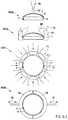
- FIGS. 6.1, 6.2, and 6.3 show an exemplary embodiment of an application of a protective film according to the disclosure as part of a method for producing a spectacle lens from a spectacle lens blank with an optically finished surface and a cylinder edge surface.
- FIGS. 1A through 1C show the production of a spectacle lens according to the related art in comparison with the production of a spectacle lens according to the disclosure, as shown in FIGS. 1D and 1E .
- FIG. 1A shows the typical process steps of the production method according to the related art.
- a semifinished product 1 is cast.
- the convex front surface usually already has its optically finished surface geometry.
- Various functional layers may be applied, as already described in the introductory part of the description.
- the semifinished product 1 is either wrapped with a wrapping film 110 of the type shown in FIG. 1B or placed in a plastic tray 111 of the type shown in FIG. 1C .
- a folding box 112 After the wrapping or insertion, the packing in a folding box 112 follows in a step 103 . Dispatch then takes place from the place where the lens is cast, for example to a prescription workshop (step 104 ). The folding box 112 with the spectacle lens blank 1 is stored there (step 105 ) until it is needed for further processing. Then, in a step 106 , unpacking from the folding box 112 and, in a further step 107 , the unwrapping or removal from the plastic tray 111 takes place. According to the related art, in a further step 108 , a protective film 2 of the type described in detail in the introductory part of the description is then applied.
- the time during which the protective film is applied to the semifinished product is usually between 0.1 and 2 hours.
- FIG. 1D shows the process steps of the production method according to the disclosure.
- Process steps 101 , 103 , 104 , 105 , and 106 as well as 109 can be found in a corresponding manner. These process steps are indicated in FIG. 1D by the reference numerals 201 , 203 , 204 , 205 , and 206 , as well as 207 .
- Process step 102 as such is omitted in the production method according to the disclosure.
- Process step 108 takes place (in a form modified according to the disclosure, as described below) instead of process step 102 in the chronological order, and is therefore identified in FIG. 1D by reference numeral 202 .
- FIG. 1E The state of the spectacle lens blank 1 in the folding box 112 in process step 203 is shown in FIG. 1E .
- the folding box packing here thus encloses a spectacle lens blank 1 with a protective film 2 according to the disclosure.
- the time during which the protective film 2 is applied to the semifinished product 1 is between one day and, if necessary, several weeks, up to 6 months in the case of so-called freeform semifinished spectacle lenses, and up to a year in the case of cast varifocal semifinished products.
- Commercially available protective films such as for example DAC Vision ST-4004, Satisloh Superstick, Lohmann DuploColl 21393, and VigTeQnos Z-6294, can be easily removed again even after this comparatively long application period.
- FIG. 2 shows a device and a method for applying a protective film 2 according to the disclosure to a spectacle lens blank 1 , in particular a semifinished product 1 .
- the protective film 2 is moved relative to the semifinished product 1 in the direction of its optically finished front surface 3 .
- the area between the front surface 3 and protective film 2 is evacuated, which is indicated by the symbol p.
- p denotes a (negative) pressure with respect to the atmospheric pressure prevailing above the protective film 2 .
- F p compressive force
- the plastic deformation of the protective film 2 is indicated in the drawing by the reference numeral 2 ′.
- the pressure-sensitive adhesive 2 a on the side of the protective film 2 facing the front surface 3 of the semifinished product 1 ensures a detachable connection between the front surface 3 of the semifinished product and the protective film 2 and between the cylinder edge surface 4 and the protective film 2 .
- FIGS. 3A and 3B specifically show an application device according to the disclosure in the form of a roller 5 with a sponge-like foam surface, wherein FIG. 3A shows the application of the protective film 2 to the optically finished surface 3 of the spectacle lens blank 1 and FIG. 3B shows the application of the protective film 2 on the cylinder edge surface 4 of the spectacle lens blank 1 .
- a spectacle lens blank 1 with a protective film 2 applied according to the disclosure can be seen in cross section in FIG. 4A .
- the protective film 2 is a protective film 2 applied fully on the optically finished surface 3 of the spectacle lens blank 1 and over the entire extent of its height h on the cylinder edge surface 4 .
- the optically finished surface 3 bears so-called functional layers 3 a and 3 b .
- 3 a is indicates the existence of a hard coating
- 3 b indicates the presence of an anti-reflective coating.
- the entire cylinder edge surface 4 is covered with the protective film 2 , this does not necessarily have to be the case according to the disclosure.
- FIG. 4B A non-schematic perspective representation of a spectacle lens blank 1 in which the protective film 2 was applied at a temperature of 40° C. can be seen in FIG. 4B .
- FIG. 4C shows a perspective representation of a spectacle lens blank 1 in which the protective film 2 was applied at a temperature of 60-70° C. While the protective film 2 applied at 60-70° C. is free from bubbles, creases and discontinuities both in the cylinder edge area 4 and on the front surface 3 , the protective film 2 , which was applied at a lower temperature, exhibits creases, particularly in the cylinder edge area 4 .
- FIGS. 5A and 5B show spectacle lens blanks with a protective film applied according to the disclosure.
- the perspective representation of a spectacle lens blank with a protective film applied according to the disclosure shown in FIG. 5A shows centering and grinding markings 7 applied with the aid of an inkjet printer.
- the perspective representation in FIG. 5B shows a spectacle lens blank with a protective film applied according to the disclosure and centering and grinding markings applied with the aid of an inkjet printer, as well as an attached block piece 8 .
- FIGS. 6.1, 6.2, and 6.3 show an exemplary embodiment of an application according to the disclosure of a protective film 2 when producing a spectacle lens from a spectacle lens blank 1 with an optically finished surface 3 and a cylinder edge surface 4 .
- the application or taping process comprises the following process steps:
- a first method step 601 the protective film 2 is fed in the form of a tape via a roller conveyor 61 with a plurality of holding devices 61 a , 61 b , 61 c , 61 d .
- the protective film 2 is heated to approximately 60-70° C., which is identified in FIG. 6.1 by the reference numeral 62 .
- a lifting mechanism 63 lifts the holder 6 , and thus the spectacle lens blank 1 , so that its finished surface 3 comes into contact with the side of the protective film 2 that has an adhesive substance, so that it smoothly clings to the finished surface 3 .
- a vacuum 65 is applied to the space 64 between the protective film 2 and the surface 3 , helping to achieve smooth clinging to the finished surface 3 and preventing formation of air pockets between the protective film 2 and the surface 3 .
- Blades 66 separate the protective film 2 in the area of the holding devices 61 a , 61 b , 61 c , and 61 d . Due to the force of gravity and the vacuum 65 , the protective film 2 also rests against the cylinder edge surface 4 of the spectacle lens blank 1 (method step 603 ).
- compressed air 67 may be applied to the adhesive-free surface of the protective film 2 via one or more compressed air nozzles 68 .
- the protective film 2 is pressed onto the effective surface 3 and the cylinder edge surface 4 .
- the protective film 2 in the area of the peripheral edge 9 is pressed against the effective surface 3 and the cylinder edge surface 4 via one or more rotatingly driven (reference numeral 70 indicates the rotational movement) rollers 69 , the angle of attack of which in the example can be varied over a range between 45° and 90°.
- the reference numeral 69 shows the rollers with an angle of attack of 90°
- the reference numeral 69 ′ shows the rollers with an angle of attack of 45°.
- the movement of the rollers 69 here always takes place in the radial direction with respect to the center axis of the spectacle lens blank 1 .
- rollers 71 are rotatingly guided in an axial direction with respect to the center axis of the spectacle lens blank 1 along the cylinder edge surface 4 (direction of rotation 72 ) and are thereby pressed against it (direction of pressure 73 ).
- process substep 605 d two half-shells 74 , 75 are pressed together in a form-fitting manner, enclosing the cylinder edge surface 4 (reference numerals 76 , 77 ).
- hot air and/or ultrasound may be applied to the cylinder edge surface 4 , which leads to bubble-free and discontinuity-free contact and adhesion of the protective film 2 to the cylinder edge surface 4 .
- Process substep 605 e shows a variant in which the spectacle lens blank 1 is guided in the direction 80 on a belt conveyor 78 .
- the cylinder edge surface 4 of the spectacle lens blank 1 comes into contact with rollers 79 , which roll on the cylinder edge surface 4 of the spectacle lens blank 1 (direction of rotation 81 ), which leads to a bubble-free and discontinuity-free contact and adhesion of the protective film 2 to the cylinder edge surface 4 .
- Process substep 605 f shows a similar variant in which the spectacle lens blank 1 is likewise guided on a belt conveyor 82 in the direction 83 .
- the spectacle lens blank 1 does not lie with the side opposite from the finished surface 3 on the belt of the belt conveyor, as in the variant according to 605 e , but with the cylinder edge surface 4 .
- a wall surface 84 opposite from the running belt of the belt conveyor 82 and the spectacle lens blank serves as a contact surface during transport in the direction 83 and, together with the running belt surface, ensures that the protective film is pressed against the cylinder edge surface 4 .
- hot air and/or ultrasound may be applied to the cylinder edge surface 4 , which leads to bubble-free and discontinuity-free contact and adhesion of the protective film 2 to the cylinder edge surface 4 .
- Process substep 605 g shows the application of a second protective film 2 a to the protective film 2 in the area of the cylinder edge surface 4 of the spectacle lens blank 1 , which results in a watertight seal.
- the “warm application” of the protective film at a surface temperature of approximately 60-70° C. is recommendable.
- a device with adjustable temperature, vacuum, substrate pressure against the protective film, substrate movement, and application time is required.
- the surface machining (opposing surface and cylinder edge surface) is ensured with sufficient reliability for base curves between BC 0.5 and 10 according to the processes presented above with the aforementioned commercially available protective films.
- Inkjet printing is possible on the surface provided with the protective film.
- a wipe test shows that the ink remains reliably on the surface.
- Identification code barcode/data matrix code/quick response
Landscapes
- Health & Medical Sciences (AREA)
- Ophthalmology & Optometry (AREA)
- Physics & Mathematics (AREA)
- General Health & Medical Sciences (AREA)
- General Physics & Mathematics (AREA)
- Optics & Photonics (AREA)
- Engineering & Computer Science (AREA)
- Manufacturing & Machinery (AREA)
- Mechanical Engineering (AREA)
- Eyeglasses (AREA)
- Grinding And Polishing Of Tertiary Curved Surfaces And Surfaces With Complex Shapes (AREA)
Applications Claiming Priority (4)
| Application Number | Priority Date | Filing Date | Title |
|---|---|---|---|
| EP18163572 | 2018-03-23 | ||
| EP18163572.3 | 2018-03-23 | ||
| EP18163572.3A EP3543003A1 (de) | 2018-03-23 | 2018-03-23 | Brillenglasrohling sowie verfahren und vorrichtung zum herstellen eines brillenglases aus einem brillenglasrohling |
| PCT/EP2019/057331 WO2019180251A1 (de) | 2018-03-23 | 2019-03-22 | Brillenglasrohling sowie verfahren und vorrichtung zum herstellen eines brillenglases aus einem brillenglasrohling |
Related Parent Applications (1)
| Application Number | Title | Priority Date | Filing Date |
|---|---|---|---|
| PCT/EP2019/057331 Continuation WO2019180251A1 (de) | 2018-03-23 | 2019-03-22 | Brillenglasrohling sowie verfahren und vorrichtung zum herstellen eines brillenglases aus einem brillenglasrohling |
Publications (2)
| Publication Number | Publication Date |
|---|---|
| US20210003862A1 US20210003862A1 (en) | 2021-01-07 |
| US11086141B2 true US11086141B2 (en) | 2021-08-10 |
Family
ID=61763866
Family Applications (1)
| Application Number | Title | Priority Date | Filing Date |
|---|---|---|---|
| US17/029,202 Active US11086141B2 (en) | 2018-03-23 | 2020-09-23 | Spectacle lens blank, and method and device for producing a spectacle lens from a spectacle lens blank |
Country Status (8)
| Country | Link |
|---|---|
| US (1) | US11086141B2 (es) |
| EP (2) | EP3543003A1 (es) |
| CN (1) | CN112118956B (es) |
| ES (1) | ES2906166T3 (es) |
| HU (1) | HUE057594T2 (es) |
| MX (1) | MX2020009959A (es) |
| PH (1) | PH12020551532A1 (es) |
| WO (1) | WO2019180251A1 (es) |
Families Citing this family (2)
| Publication number | Priority date | Publication date | Assignee | Title |
|---|---|---|---|---|
| EP4035832A1 (en) * | 2021-01-28 | 2022-08-03 | Carl Zeiss Vision International GmbH | Blocking piece and method for vacuum blocking a lens blank |
| EP4043193A1 (en) | 2021-02-15 | 2022-08-17 | Carl Zeiss Vision International GmbH | Method of manufacturing a spectacle lens and method of controlling manufacturing tools for manufacturing spectacle lenses |
Citations (35)
| Publication number | Priority date | Publication date | Assignee | Title |
|---|---|---|---|---|
| DE2208444A1 (de) | 1971-02-24 | 1972-09-28 | Coburn Optical Industries, Inc., Muskoee, OkIa. (V.StA.) | Linsentragkörper |
| DE7723333U1 (de) | 1976-07-26 | 1977-11-03 | I O R Ind Ottiche Riunite S R | Verpackung fuer Prillenglaeser |
| WO1980002431A1 (en) | 1979-05-08 | 1980-11-13 | Minnesota Mining & Mfg | Conformable,multilayered,pressure-sensitive adhesive tape and a method of bonding therewith a fusible metal alloy to an ophthalmic lens blank |
| US4277891A (en) * | 1980-06-13 | 1981-07-14 | American Optical Corporation | Lens tape cutter |
| US4300821A (en) | 1979-02-28 | 1981-11-17 | Essilor International Cie Generale D'optique | Photochromic ophthalmic lens of organic materials |
| JPS60135167A (ja) | 1983-12-24 | 1985-07-18 | Masato Nishikata | レンズの表面処理方法 |
| EP0285490A1 (fr) | 1987-03-30 | 1988-10-05 | ESSILOR INTERNATIONAL Compagnie Générale d'Optique | Procédé et appareil pour coller un film protecteur sur une face d'une série de lentilles ophtalmiques |
| US5343657A (en) | 1992-09-18 | 1994-09-06 | Venture Tape Corporation | Method and apparatus for masking removable optical lens markings during lens grinding |
| EP0698798A2 (de) | 1994-08-26 | 1996-02-28 | Leybold Aktiengesellschaft | Beschichtete optische Kunststofflinse |
| WO1997010923A1 (en) | 1995-09-18 | 1997-03-27 | Minnesota Mining And Manufacturing Company | Lens blank blocking adhesive film |
| WO1997010924A1 (en) | 1995-09-18 | 1997-03-27 | Minnesota Mining And Manufacturing Company | Thermoplastic lens blocking material |
| EP0955147A1 (en) | 1996-02-29 | 1999-11-10 | Hoya Corporation | Method of injection molding plastic lens |
| US6089713A (en) | 1997-01-16 | 2000-07-18 | Carl-Zeiss-Stiftung | Spectacle lens with spherical front side and multifocal back side and process for its production |
| US6103148A (en) | 1998-02-19 | 2000-08-15 | Technology Resources International Corporation | Method for curing a lens-forming fluid |
| US6109748A (en) * | 1994-02-28 | 2000-08-29 | Sola International, Inc. | Lens wafer with removable coating |
| US6124906A (en) | 1997-09-12 | 2000-09-26 | Ibm Corporation | Wedge shaped light guide providing enhanced polarized light to a backlight liquid crystal display |
| WO2000068326A1 (en) | 1999-05-05 | 2000-11-16 | Vision-Ease Lens Inc. | Temporary protective layer on polymeric articles |
| WO2002092524A1 (fr) | 2001-05-17 | 2002-11-21 | Essilor International Compagnie Generale D'optique | Procede de preparation d'un verre apte au debordage, verre ainsi obtenu et procede de debordage d'un tel verre. |
| EP1269223A1 (en) | 2000-01-26 | 2003-01-02 | Sola International Holdings Limited | Anti-static, anti-reflection coating |
| WO2004110946A1 (en) | 2003-06-13 | 2004-12-23 | Essilor International Compagnie Generale D'optique | Method for treating a lens apt to trimming |
| WO2007001251A1 (en) | 2005-06-13 | 2007-01-04 | Su, Chen-Ming | Method for machining a lens and adhesive label useful when machining the lens |
| US20080117382A1 (en) | 2003-09-26 | 2008-05-22 | Essilor International Compagnie Generale D'optique | Electrostatic Film Coated Ophthalmic Lens And Method For Edging Same |
| DE102007007161A1 (de) | 2007-02-09 | 2008-08-14 | Satisloh Gmbh | Verfahren, Vorrichtung und Material zum Blocken von Werkstücken, insbesondere Brillengläsern, für deren Bearbeitung und/oder Beschichtung |
| JP2008191186A (ja) | 2007-01-31 | 2008-08-21 | Hoya Corp | 眼鏡用プラスチックレンズ成形用ガスケット及び成形型並びにその型を用いた眼鏡用プラスチックレンズ及びガスケットの製造方法 |
| EP2138271A1 (en) | 2008-06-26 | 2009-12-30 | Satisloh AG | Method for manufacturing spectacle lenses according to a prescription |
| DE102010048088A1 (de) | 2010-10-01 | 2012-04-05 | Carl Zeiss Vision Gmbh | Optische Linse mit kratzfester Entspiegelungsschicht |
| US20130075465A1 (en) | 2010-10-04 | 2013-03-28 | Schneider Gmbh & Co. Kg | Apparatus and method for working an optical lens and also an optical lens and a transporting container for optical lenses |
| US20130206328A1 (en) | 2010-10-21 | 2013-08-15 | Essilor International (Compagnie Generale D'optique) | Process for applying a film structure onto a lens blank |
| DE102012009691A1 (de) | 2012-05-15 | 2013-11-21 | Carl Zeiss Vision International Gmbh | Antifog-Beschichtung |
| DE102013208310A1 (de) | 2013-05-06 | 2014-11-06 | Carl Zeiss Vision International Gmbh | Optisches Element mit einer Beschichtung hoher Diffusivität |
| DE102015209794A1 (de) | 2015-05-28 | 2016-12-01 | Carl Zeiss Vision International Gmbh | Verfahren zur Herstellung eines optischen Glases mit Antifog-Beschichtung |
| WO2017046803A1 (en) | 2015-09-18 | 2017-03-23 | Shamir Optical Industry Ltd. | Methods and apparatus for repairing delaminated lenses-on-blocks |
| US10010994B2 (en) * | 2012-12-11 | 2018-07-03 | Essilor International (Compagnie Generale D'optique) | Method for taping an optical lens member |
| US20190070808A1 (en) * | 2017-09-01 | 2019-03-07 | Thalmic Labs Inc. | Systems, devices, and methods for manufacturing an eyeglass lens |
| US20200262163A1 (en) * | 2015-12-10 | 2020-08-20 | Essilor International | Method for packaging a spectacle lens |
Family Cites Families (2)
| Publication number | Priority date | Publication date | Assignee | Title |
|---|---|---|---|---|
| DE102008022360C5 (de) | 2008-05-06 | 2014-04-10 | Schneider Gmbh & Co. Kg | Blockstation zum Aufblocken von Brillenglasrohlingen auf ein Blockstück |
| DE102010048089B4 (de) | 2010-10-01 | 2016-09-01 | Carl Zeiss Vision International Gmbh | Verfahren zur Erzeugung einer mehrere Schichten aufweisenden antistatischen Beschichtung für ein Linsenelement |
-
2018
- 2018-03-23 EP EP18163572.3A patent/EP3543003A1/de not_active Withdrawn
-
2019
- 2019-03-22 ES ES19711396T patent/ES2906166T3/es active Active
- 2019-03-22 CN CN201980034612.3A patent/CN112118956B/zh active Active
- 2019-03-22 WO PCT/EP2019/057331 patent/WO2019180251A1/de active Application Filing
- 2019-03-22 EP EP19711396.2A patent/EP3768501B1/de active Active
- 2019-03-22 HU HUE19711396A patent/HUE057594T2/hu unknown
- 2019-03-22 MX MX2020009959A patent/MX2020009959A/es unknown
-
2020
- 2020-09-23 PH PH12020551532A patent/PH12020551532A1/en unknown
- 2020-09-23 US US17/029,202 patent/US11086141B2/en active Active
Patent Citations (48)
| Publication number | Priority date | Publication date | Assignee | Title |
|---|---|---|---|---|
| US3704558A (en) | 1971-02-24 | 1972-12-05 | Coburn Mfg Co | Lens block |
| DE2208444A1 (de) | 1971-02-24 | 1972-09-28 | Coburn Optical Industries, Inc., Muskoee, OkIa. (V.StA.) | Linsentragkörper |
| DE7723333U1 (de) | 1976-07-26 | 1977-11-03 | I O R Ind Ottiche Riunite S R | Verpackung fuer Prillenglaeser |
| US4300821A (en) | 1979-02-28 | 1981-11-17 | Essilor International Cie Generale D'optique | Photochromic ophthalmic lens of organic materials |
| DE3007572C2 (de) | 1979-02-28 | 1982-12-23 | Essilor International (Compagnie Générale d'Optique), 94028 Créteil, Val-de-Marne | Fotochromatische Brillenlinse aus organischem Werkstoff |
| WO1980002431A1 (en) | 1979-05-08 | 1980-11-13 | Minnesota Mining & Mfg | Conformable,multilayered,pressure-sensitive adhesive tape and a method of bonding therewith a fusible metal alloy to an ophthalmic lens blank |
| US4277891A (en) * | 1980-06-13 | 1981-07-14 | American Optical Corporation | Lens tape cutter |
| JPS60135167A (ja) | 1983-12-24 | 1985-07-18 | Masato Nishikata | レンズの表面処理方法 |
| EP0285490A1 (fr) | 1987-03-30 | 1988-10-05 | ESSILOR INTERNATIONAL Compagnie Générale d'Optique | Procédé et appareil pour coller un film protecteur sur une face d'une série de lentilles ophtalmiques |
| US4826548A (en) | 1987-03-30 | 1989-05-02 | Essilor International (Compagnie Generale D'optique) | Method for applying a protective film on one face of a series of ophthalmic lenses |
| US4959118A (en) | 1987-03-30 | 1990-09-25 | Essilor International (Compagnie Generale D'optique) | Apparatus for applying a protective film on one face of a series of ophthalmic lenses |
| US5343657A (en) | 1992-09-18 | 1994-09-06 | Venture Tape Corporation | Method and apparatus for masking removable optical lens markings during lens grinding |
| US6109748A (en) * | 1994-02-28 | 2000-08-29 | Sola International, Inc. | Lens wafer with removable coating |
| EP0698798A2 (de) | 1994-08-26 | 1996-02-28 | Leybold Aktiengesellschaft | Beschichtete optische Kunststofflinse |
| CA2157070C (en) | 1994-08-26 | 2001-05-01 | Walter Zultzke | Optical lens of transparent plastic |
| WO1997010924A1 (en) | 1995-09-18 | 1997-03-27 | Minnesota Mining And Manufacturing Company | Thermoplastic lens blocking material |
| US5916017A (en) | 1995-09-18 | 1999-06-29 | Minnesota Mining And Manufacturing Company | Preformed ophthalmic lens base block |
| WO1997010923A1 (en) | 1995-09-18 | 1997-03-27 | Minnesota Mining And Manufacturing Company | Lens blank blocking adhesive film |
| EP0955147A1 (en) | 1996-02-29 | 1999-11-10 | Hoya Corporation | Method of injection molding plastic lens |
| US6089713A (en) | 1997-01-16 | 2000-07-18 | Carl-Zeiss-Stiftung | Spectacle lens with spherical front side and multifocal back side and process for its production |
| EP2266754B1 (de) | 1997-01-16 | 2016-08-31 | Carl Zeiss Vision GmbH | Vakuumspannfutter zum Haltern eines Brillenrohlings |
| US6124906A (en) | 1997-09-12 | 2000-09-26 | Ibm Corporation | Wedge shaped light guide providing enhanced polarized light to a backlight liquid crystal display |
| US6103148A (en) | 1998-02-19 | 2000-08-15 | Technology Resources International Corporation | Method for curing a lens-forming fluid |
| WO2000068326A1 (en) | 1999-05-05 | 2000-11-16 | Vision-Ease Lens Inc. | Temporary protective layer on polymeric articles |
| EP1269223A1 (en) | 2000-01-26 | 2003-01-02 | Sola International Holdings Limited | Anti-static, anti-reflection coating |
| WO2002092524A1 (fr) | 2001-05-17 | 2002-11-21 | Essilor International Compagnie Generale D'optique | Procede de preparation d'un verre apte au debordage, verre ainsi obtenu et procede de debordage d'un tel verre. |
| US8252368B2 (en) | 2001-05-17 | 2012-08-28 | Essilor International Compagnie Generale D 'optique | Method for preparing a glass convenient for trimming, a glass thus obtained, and method for trimming such a glass |
| WO2004110946A1 (en) | 2003-06-13 | 2004-12-23 | Essilor International Compagnie Generale D'optique | Method for treating a lens apt to trimming |
| US20080117382A1 (en) | 2003-09-26 | 2008-05-22 | Essilor International Compagnie Generale D'optique | Electrostatic Film Coated Ophthalmic Lens And Method For Edging Same |
| WO2007001251A1 (en) | 2005-06-13 | 2007-01-04 | Su, Chen-Ming | Method for machining a lens and adhesive label useful when machining the lens |
| JP2008191186A (ja) | 2007-01-31 | 2008-08-21 | Hoya Corp | 眼鏡用プラスチックレンズ成形用ガスケット及び成形型並びにその型を用いた眼鏡用プラスチックレンズ及びガスケットの製造方法 |
| DE102007007161A1 (de) | 2007-02-09 | 2008-08-14 | Satisloh Gmbh | Verfahren, Vorrichtung und Material zum Blocken von Werkstücken, insbesondere Brillengläsern, für deren Bearbeitung und/oder Beschichtung |
| EP2138271A1 (en) | 2008-06-26 | 2009-12-30 | Satisloh AG | Method for manufacturing spectacle lenses according to a prescription |
| DE102010048088A1 (de) | 2010-10-01 | 2012-04-05 | Carl Zeiss Vision Gmbh | Optische Linse mit kratzfester Entspiegelungsschicht |
| US9817155B2 (en) | 2010-10-01 | 2017-11-14 | Carl Zeiss Vision International Gmbh | Optical lens with scratch-resistant anti-reflective layer |
| US20130075465A1 (en) | 2010-10-04 | 2013-03-28 | Schneider Gmbh & Co. Kg | Apparatus and method for working an optical lens and also an optical lens and a transporting container for optical lenses |
| US20130206328A1 (en) | 2010-10-21 | 2013-08-15 | Essilor International (Compagnie Generale D'optique) | Process for applying a film structure onto a lens blank |
| DE102012009691A1 (de) | 2012-05-15 | 2013-11-21 | Carl Zeiss Vision International Gmbh | Antifog-Beschichtung |
| US9500860B2 (en) | 2012-05-15 | 2016-11-22 | Carl Zeiss Vision International Gmbh | Anti-fog coating |
| US10338278B2 (en) | 2012-05-15 | 2019-07-02 | Carl Zeiss Vision International Gmbh | Anti-fog coating |
| US10010994B2 (en) * | 2012-12-11 | 2018-07-03 | Essilor International (Compagnie Generale D'optique) | Method for taping an optical lens member |
| US9778484B2 (en) | 2013-05-06 | 2017-10-03 | Carl Zeiss Vision International Gmbh | Optical element having a coating of high diffusivity |
| DE102013208310A1 (de) | 2013-05-06 | 2014-11-06 | Carl Zeiss Vision International Gmbh | Optisches Element mit einer Beschichtung hoher Diffusivität |
| DE102015209794A1 (de) | 2015-05-28 | 2016-12-01 | Carl Zeiss Vision International Gmbh | Verfahren zur Herstellung eines optischen Glases mit Antifog-Beschichtung |
| US10259744B2 (en) | 2015-05-28 | 2019-04-16 | Carl Zeiss Vision International Gmbh | Process for producing an optical glass with an anti-fog coating |
| WO2017046803A1 (en) | 2015-09-18 | 2017-03-23 | Shamir Optical Industry Ltd. | Methods and apparatus for repairing delaminated lenses-on-blocks |
| US20200262163A1 (en) * | 2015-12-10 | 2020-08-20 | Essilor International | Method for packaging a spectacle lens |
| US20190070808A1 (en) * | 2017-09-01 | 2019-03-07 | Thalmic Labs Inc. | Systems, devices, and methods for manufacturing an eyeglass lens |
Non-Patent Citations (5)
| Title |
|---|
| "Ophthalmic optics—Spectacle lenses—Vocabulary (ISO 13666:2012)," German and English version EN ISO 13666:2012, Oct. 2013. |
| Diepes et al. "Optik and Technik der Brille" [Optics and Technology of Spectacles], Optische Fachveröffentlichung GmbH, Heidelberg, 2005, p. 558, entry "Halbfertigprodukt [Semifinished spectacle lens products or semifinished spectacle lenses]," provided in lieu of p. 560 of the first edition 2002. Relevance is found at least in paragraph [0003] of the specification. |
| Din 8580 "Fertigungsverfahren [Manufacturing processes]," Deutsches Institut fuer Normung e.V., Sep. 2003. Relevance is found at least in paragraph [0011] of the specification. |
| International Preliminary Examination Report issued in PCT/EP2019/057331, to which this application claims priority, dated Feb. 27, 2020, and English-language translation thereof. |
| International Search Report issued in PCT/EP2019/057331, to which this application claims priority, dated Jun. 21, 2019, and English-language translation thereof. |
Also Published As
| Publication number | Publication date |
|---|---|
| EP3768501A1 (de) | 2021-01-27 |
| HUE057594T2 (hu) | 2022-05-28 |
| MX2020009959A (es) | 2020-12-10 |
| PH12020551532A1 (en) | 2021-06-07 |
| EP3768501B1 (de) | 2021-11-10 |
| CN112118956B (zh) | 2022-08-05 |
| WO2019180251A1 (de) | 2019-09-26 |
| EP3543003A1 (de) | 2019-09-25 |
| US20210003862A1 (en) | 2021-01-07 |
| CN112118956A (zh) | 2020-12-22 |
| ES2906166T3 (es) | 2022-04-13 |
Similar Documents
| Publication | Publication Date | Title |
|---|---|---|
| US11086141B2 (en) | Spectacle lens blank, and method and device for producing a spectacle lens from a spectacle lens blank | |
| EP1864181B1 (en) | Coatings for ophthalmic lens elements | |
| KR101125627B1 (ko) | 정전기 필름으로 피복된 안과용 렌즈 및 상기 렌즈를 에징하는 방법 | |
| CN107924067A (zh) | 镜片保护系统 | |
| EP0660769B1 (en) | Method and apparatus for masking removable optical lens markings during lens grinding | |
| KR20070087006A (ko) | 에지 연삭을 위한 광학 유리 제조방법, 그에 따라 생성된유리 및 이러한 유리를 에지 연삭하는 방법 | |
| CN108329861A (zh) | 一种应用于曲面显示屏的热定型保护膜 | |
| CN111867818A (zh) | 光学镜片和涂覆光学镜片的边缘表面的方法 | |
| EP3145704B1 (en) | Optical lens coated with a patterned removable film and method for edging such a lens | |
| JP6593116B2 (ja) | 印刷層付き板およびこれを用いた表示装置 | |
| CN100478740C (zh) | 覆盖有静电薄膜的眼科镜片以及对该镜片进行修边的方法 | |
| US10274656B2 (en) | Optical device with a functionalised coating and method for such optical device | |
| CN105750155A (zh) | 一种uv转印工艺 | |
| KR100874188B1 (ko) | 코팅층에 렌즈 정보가 표시된 광학렌즈 및 그 제조방법 | |
| WO2021113857A1 (en) | Anti-fog lens covering systems | |
| MX2011008404A (es) | Modificacion superficial de recubrimiento hidrofobico y/o oleofobico. | |
| CN106574987A (zh) | 包括保护性可去除的膜的光学镜片 | |
| US20140171570A1 (en) | Protective layer for optical devices | |
| JP7302649B2 (ja) | 車載用表示装置用カバーガラス及び車載用表示装置 | |
| JP6544228B2 (ja) | 被覆用品及び被覆付部品 | |
| AU2012200550B2 (en) | Coatings for ophthalmic lens elements | |
| AU2006220223A1 (en) | Coatings for ophthalmic lens elements |
Legal Events
| Date | Code | Title | Description |
|---|---|---|---|
| FEPP | Fee payment procedure |
Free format text: ENTITY STATUS SET TO UNDISCOUNTED (ORIGINAL EVENT CODE: BIG.); ENTITY STATUS OF PATENT OWNER: LARGE ENTITY |
|
| AS | Assignment |
Owner name: CARL ZEISS VISION GMBH, GERMANY Free format text: ASSIGNMENT OF ASSIGNORS INTEREST;ASSIGNORS:MESCHENMOSER, RALF;VALLERIUS, RALF;HAENSCH, SVEN;SIGNING DATES FROM 20201030 TO 20201104;REEL/FRAME:054428/0182 |
|
| AS | Assignment |
Owner name: CARL ZEISS VISION INTERNATIONAL GMBH, GERMANY Free format text: ASSIGNMENT OF ASSIGNORS INTEREST;ASSIGNOR:CARL ZEISS VISION GMBH;REEL/FRAME:054440/0573 Effective date: 20201110 |
|
| STPP | Information on status: patent application and granting procedure in general |
Free format text: DOCKETED NEW CASE - READY FOR EXAMINATION |
|
| STPP | Information on status: patent application and granting procedure in general |
Free format text: NON FINAL ACTION MAILED |
|
| STPP | Information on status: patent application and granting procedure in general |
Free format text: RESPONSE TO NON-FINAL OFFICE ACTION ENTERED AND FORWARDED TO EXAMINER |
|
| STPP | Information on status: patent application and granting procedure in general |
Free format text: NOTICE OF ALLOWANCE MAILED -- APPLICATION RECEIVED IN OFFICE OF PUBLICATIONS |
|
| STPP | Information on status: patent application and granting procedure in general |
Free format text: PUBLICATIONS -- ISSUE FEE PAYMENT RECEIVED |
|
| STPP | Information on status: patent application and granting procedure in general |
Free format text: PUBLICATIONS -- ISSUE FEE PAYMENT VERIFIED |
|
| STCF | Information on status: patent grant |
Free format text: PATENTED CASE |