US11028001B2 - High temperature glass melting vessel - Google Patents
High temperature glass melting vessel Download PDFInfo
- Publication number
- US11028001B2 US11028001B2 US16/348,142 US201716348142A US11028001B2 US 11028001 B2 US11028001 B2 US 11028001B2 US 201716348142 A US201716348142 A US 201716348142A US 11028001 B2 US11028001 B2 US 11028001B2
- Authority
- US
- United States
- Prior art keywords
- vessel
- glass
- glass melt
- electrode
- refractory material
- Prior art date
- Legal status (The legal status is an assumption and is not a legal conclusion. Google has not performed a legal analysis and makes no representation as to the accuracy of the status listed.)
- Active, expires
Links
- 239000011521 glass Substances 0.000 title claims description 100
- 238000002844 melting Methods 0.000 title claims description 95
- 230000008018 melting Effects 0.000 title claims description 95
- 239000000156 glass melt Substances 0.000 claims abstract description 103
- 239000011819 refractory material Substances 0.000 claims abstract description 73
- MCMNRKCIXSYSNV-UHFFFAOYSA-N Zirconium dioxide Chemical compound O=[Zr]=O MCMNRKCIXSYSNV-UHFFFAOYSA-N 0.000 claims abstract description 20
- 230000015556 catabolic process Effects 0.000 claims abstract description 16
- 238000004519 manufacturing process Methods 0.000 claims description 27
- 239000000203 mixture Substances 0.000 claims description 25
- 238000000034 method Methods 0.000 claims description 19
- BASFCYQUMIYNBI-UHFFFAOYSA-N platinum Chemical compound [Pt] BASFCYQUMIYNBI-UHFFFAOYSA-N 0.000 claims description 12
- 239000000463 material Substances 0.000 claims description 7
- 229910045601 alloy Inorganic materials 0.000 claims description 6
- 239000000956 alloy Substances 0.000 claims description 6
- 229910052697 platinum Inorganic materials 0.000 claims description 6
- 238000012545 processing Methods 0.000 claims description 6
- ZOKXTWBITQBERF-UHFFFAOYSA-N Molybdenum Chemical compound [Mo] ZOKXTWBITQBERF-UHFFFAOYSA-N 0.000 claims description 5
- 229910052750 molybdenum Inorganic materials 0.000 claims description 5
- 239000011733 molybdenum Substances 0.000 claims description 5
- ATJFFYVFTNAWJD-UHFFFAOYSA-N Tin Chemical compound [Sn] ATJFFYVFTNAWJD-UHFFFAOYSA-N 0.000 claims description 4
- 229910052718 tin Inorganic materials 0.000 claims description 4
- 239000011135 tin Substances 0.000 claims description 4
- 239000006060 molten glass Substances 0.000 description 26
- 238000002156 mixing Methods 0.000 description 19
- 239000002994 raw material Substances 0.000 description 14
- VYPSYNLAJGMNEJ-UHFFFAOYSA-N Silicium dioxide Chemical compound O=[Si]=O VYPSYNLAJGMNEJ-UHFFFAOYSA-N 0.000 description 8
- 230000005484 gravity Effects 0.000 description 7
- PNEYBMLMFCGWSK-UHFFFAOYSA-N aluminium oxide Inorganic materials [O-2].[O-2].[O-2].[Al+3].[Al+3] PNEYBMLMFCGWSK-UHFFFAOYSA-N 0.000 description 6
- 238000010438 heat treatment Methods 0.000 description 6
- 238000011144 upstream manufacturing Methods 0.000 description 6
- 230000003750 conditioning effect Effects 0.000 description 5
- 230000007797 corrosion Effects 0.000 description 5
- 238000005260 corrosion Methods 0.000 description 5
- 239000007772 electrode material Substances 0.000 description 5
- 239000006025 fining agent Substances 0.000 description 5
- 230000007246 mechanism Effects 0.000 description 5
- KDLHZDBZIXYQEI-UHFFFAOYSA-N Palladium Chemical compound [Pd] KDLHZDBZIXYQEI-UHFFFAOYSA-N 0.000 description 4
- 239000003513 alkali Substances 0.000 description 4
- QVGXLLKOCUKJST-UHFFFAOYSA-N atomic oxygen Chemical compound [O] QVGXLLKOCUKJST-UHFFFAOYSA-N 0.000 description 4
- 229910052681 coesite Inorganic materials 0.000 description 4
- 229910052593 corundum Inorganic materials 0.000 description 4
- 229910052906 cristobalite Inorganic materials 0.000 description 4
- 230000004927 fusion Effects 0.000 description 4
- 239000001301 oxygen Substances 0.000 description 4
- 229910052760 oxygen Inorganic materials 0.000 description 4
- 239000011214 refractory ceramic Substances 0.000 description 4
- 239000000377 silicon dioxide Substances 0.000 description 4
- 229910052682 stishovite Inorganic materials 0.000 description 4
- 229910052905 tridymite Inorganic materials 0.000 description 4
- 229910001845 yogo sapphire Inorganic materials 0.000 description 4
- 230000008901 benefit Effects 0.000 description 3
- 230000007547 defect Effects 0.000 description 3
- 229910052751 metal Inorganic materials 0.000 description 3
- 239000002184 metal Substances 0.000 description 3
- 230000037361 pathway Effects 0.000 description 3
- 238000003860 storage Methods 0.000 description 3
- 238000012546 transfer Methods 0.000 description 3
- XEEYBQQBJWHFJM-UHFFFAOYSA-N Iron Chemical compound [Fe] XEEYBQQBJWHFJM-UHFFFAOYSA-N 0.000 description 2
- 239000011449 brick Substances 0.000 description 2
- 229910010293 ceramic material Inorganic materials 0.000 description 2
- 239000003638 chemical reducing agent Substances 0.000 description 2
- 238000002485 combustion reaction Methods 0.000 description 2
- 239000004020 conductor Substances 0.000 description 2
- 238000001816 cooling Methods 0.000 description 2
- 230000001419 dependent effect Effects 0.000 description 2
- 238000013461 design Methods 0.000 description 2
- 239000007789 gas Substances 0.000 description 2
- 238000005816 glass manufacturing process Methods 0.000 description 2
- 239000000155 melt Substances 0.000 description 2
- 150000002739 metals Chemical class 0.000 description 2
- VNWKTOKETHGBQD-UHFFFAOYSA-N methane Chemical compound C VNWKTOKETHGBQD-UHFFFAOYSA-N 0.000 description 2
- 238000012986 modification Methods 0.000 description 2
- 230000004048 modification Effects 0.000 description 2
- 229910052763 palladium Inorganic materials 0.000 description 2
- -1 platinum group metals Chemical class 0.000 description 2
- 239000010970 precious metal Substances 0.000 description 2
- 238000006722 reduction reaction Methods 0.000 description 2
- 229910052703 rhodium Inorganic materials 0.000 description 2
- 239000010948 rhodium Substances 0.000 description 2
- MHOVAHRLVXNVSD-UHFFFAOYSA-N rhodium atom Chemical compound [Rh] MHOVAHRLVXNVSD-UHFFFAOYSA-N 0.000 description 2
- 230000035939 shock Effects 0.000 description 2
- 239000000126 substance Substances 0.000 description 2
- 229910052684 Cerium Inorganic materials 0.000 description 1
- KKCBUQHMOMHUOY-UHFFFAOYSA-N Na2O Inorganic materials [O-2].[Na+].[Na+] KKCBUQHMOMHUOY-UHFFFAOYSA-N 0.000 description 1
- 229910000629 Rh alloy Inorganic materials 0.000 description 1
- KJTLSVCANCCWHF-UHFFFAOYSA-N Ruthenium Chemical compound [Ru] KJTLSVCANCCWHF-UHFFFAOYSA-N 0.000 description 1
- RTAQQCXQSZGOHL-UHFFFAOYSA-N Titanium Chemical compound [Ti] RTAQQCXQSZGOHL-UHFFFAOYSA-N 0.000 description 1
- 101150071882 US17 gene Proteins 0.000 description 1
- 230000002411 adverse Effects 0.000 description 1
- 229910052787 antimony Inorganic materials 0.000 description 1
- WATWJIUSRGPENY-UHFFFAOYSA-N antimony atom Chemical compound [Sb] WATWJIUSRGPENY-UHFFFAOYSA-N 0.000 description 1
- 229910052785 arsenic Inorganic materials 0.000 description 1
- RQNWIZPPADIBDY-UHFFFAOYSA-N arsenic atom Chemical compound [As] RQNWIZPPADIBDY-UHFFFAOYSA-N 0.000 description 1
- ZMIGMASIKSOYAM-UHFFFAOYSA-N cerium Chemical compound [Ce][Ce][Ce][Ce][Ce][Ce][Ce][Ce][Ce][Ce][Ce][Ce][Ce][Ce][Ce][Ce][Ce][Ce][Ce][Ce][Ce][Ce][Ce][Ce][Ce][Ce][Ce][Ce][Ce][Ce][Ce][Ce][Ce][Ce][Ce][Ce][Ce][Ce] ZMIGMASIKSOYAM-UHFFFAOYSA-N 0.000 description 1
- 230000008859 change Effects 0.000 description 1
- 238000006243 chemical reaction Methods 0.000 description 1
- 239000003795 chemical substances by application Substances 0.000 description 1
- 150000001875 compounds Chemical class 0.000 description 1
- 230000001010 compromised effect Effects 0.000 description 1
- 239000000109 continuous material Substances 0.000 description 1
- 238000004090 dissolution Methods 0.000 description 1
- 238000009826 distribution Methods 0.000 description 1
- 238000002474 experimental method Methods 0.000 description 1
- 239000012530 fluid Substances 0.000 description 1
- 239000000446 fuel Substances 0.000 description 1
- 238000003286 fusion draw glass process Methods 0.000 description 1
- 238000007499 fusion processing Methods 0.000 description 1
- 238000007496 glass forming Methods 0.000 description 1
- 238000009413 insulation Methods 0.000 description 1
- 229910052741 iridium Inorganic materials 0.000 description 1
- GKOZUEZYRPOHIO-UHFFFAOYSA-N iridium atom Chemical compound [Ir] GKOZUEZYRPOHIO-UHFFFAOYSA-N 0.000 description 1
- 229910052742 iron Inorganic materials 0.000 description 1
- 238000007726 management method Methods 0.000 description 1
- 238000010309 melting process Methods 0.000 description 1
- 229910044991 metal oxide Inorganic materials 0.000 description 1
- 150000004706 metal oxides Chemical class 0.000 description 1
- 239000003345 natural gas Substances 0.000 description 1
- 230000008520 organization Effects 0.000 description 1
- 229910052762 osmium Inorganic materials 0.000 description 1
- SYQBFIAQOQZEGI-UHFFFAOYSA-N osmium atom Chemical compound [Os] SYQBFIAQOQZEGI-UHFFFAOYSA-N 0.000 description 1
- PXXKQOPKNFECSZ-UHFFFAOYSA-N platinum rhodium Chemical compound [Rh].[Pt] PXXKQOPKNFECSZ-UHFFFAOYSA-N 0.000 description 1
- 238000011084 recovery Methods 0.000 description 1
- 229910052702 rhenium Inorganic materials 0.000 description 1
- WUAPFZMCVAUBPE-UHFFFAOYSA-N rhenium atom Chemical compound [Re] WUAPFZMCVAUBPE-UHFFFAOYSA-N 0.000 description 1
- 238000005096 rolling process Methods 0.000 description 1
- 229910052707 ruthenium Inorganic materials 0.000 description 1
- 238000000926 separation method Methods 0.000 description 1
- 238000003283 slot draw process Methods 0.000 description 1
- 239000007787 solid Substances 0.000 description 1
- 239000000758 substrate Substances 0.000 description 1
- 229910052715 tantalum Inorganic materials 0.000 description 1
- GUVRBAGPIYLISA-UHFFFAOYSA-N tantalum atom Chemical compound [Ta] GUVRBAGPIYLISA-UHFFFAOYSA-N 0.000 description 1
- XOLBLPGZBRYERU-UHFFFAOYSA-N tin dioxide Chemical compound O=[Sn]=O XOLBLPGZBRYERU-UHFFFAOYSA-N 0.000 description 1
- 229910001887 tin oxide Inorganic materials 0.000 description 1
- 229910052719 titanium Inorganic materials 0.000 description 1
- 239000010936 titanium Substances 0.000 description 1
- 230000007704 transition Effects 0.000 description 1
- WFKWXMTUELFFGS-UHFFFAOYSA-N tungsten Chemical compound [W] WFKWXMTUELFFGS-UHFFFAOYSA-N 0.000 description 1
- 229910052721 tungsten Inorganic materials 0.000 description 1
- 239000010937 tungsten Substances 0.000 description 1
Images


Classifications
-
- C—CHEMISTRY; METALLURGY
- C03—GLASS; MINERAL OR SLAG WOOL
- C03B—MANUFACTURE, SHAPING, OR SUPPLEMENTARY PROCESSES
- C03B5/00—Melting in furnaces; Furnaces so far as specially adapted for glass manufacture
- C03B5/02—Melting in furnaces; Furnaces so far as specially adapted for glass manufacture in electric furnaces, e.g. by dielectric heating
- C03B5/027—Melting in furnaces; Furnaces so far as specially adapted for glass manufacture in electric furnaces, e.g. by dielectric heating by passing an electric current between electrodes immersed in the glass bath, i.e. by direct resistance heating
- C03B5/03—Tank furnaces
-
- C—CHEMISTRY; METALLURGY
- C03—GLASS; MINERAL OR SLAG WOOL
- C03B—MANUFACTURE, SHAPING, OR SUPPLEMENTARY PROCESSES
- C03B5/00—Melting in furnaces; Furnaces so far as specially adapted for glass manufacture
- C03B5/16—Special features of the melting process; Auxiliary means specially adapted for glass-melting furnaces
- C03B5/42—Details of construction of furnace walls, e.g. to prevent corrosion; Use of materials for furnace walls
- C03B5/43—Use of materials for furnace walls, e.g. fire-bricks
Definitions
- the present invention relates generally to a glass melt delivery system vessel and more particularly to a vessel for high temperature glass manufacturing.
- Glass compositions for use, for example, in high resolution display applications can have considerably high melting temperatures. Such compositions are often melted in a glass melt delivery system vessel, such as a melting vessel or furnace having a refractory material at an interface between the vessel wall and the glass melt. Power is provided to the melting vessel through use of electrodes and/or combustion of a combustible fluid.
- a glass melt delivery system vessel such as a melting vessel or furnace having a refractory material at an interface between the vessel wall and the glass melt.
- Power is provided to the melting vessel through use of electrodes and/or combustion of a combustible fluid.
- High temperature glass melts are, however, corrosive to refractory materials and have a tendency to thin the refractory over time, which can, in turn, limit vessel life.
- corrosion of the refractory materials can cause undesirable defects in the final glass product, including defects caused by dissolution of the refractory material into the glass melt. Accordingly, corrosion resistance is an important property for a glass melt delivery system vessel refractory material.
- thermal shock resistance and electrical resistivity address the potential for the refractory material to fail and, depending on the severity of the failure, the useful life of the melting vessel may be compromised or the affected region of the refractory material may create solid defects.
- the electrical resistivity of the refractory material must be high enough that the majority of electrical conduction occurs in the glass melt rather than the refractory material. In general, this of less practical concern when the electrical resistivity of the glass melt is substantially lower than the electrical resistivity of the refractory. However, it can be of significant concern when the electrical resistivity of the glass melt is approximately equal to or higher than the electrical resistivity of the refractory.
- the relative difference between the resistivity of the glass melt and the refractory is not only composition dependent but also temperature dependent.
- the refractory material is increasingly electrically conductive with increasing temperature, such that at the temperatures prevailing in high temperature glass melting operations, the electrical resistivity of the refractory material at the interface between the refractory material and a specific glass melt may be lower than that of the glass melt, whereas the electrical resistivity of the refractory may be higher than that of the same glass melt at lower temperatures.
- the electrical resistivity of the refractory material relative to that of the glass melt affects the amount of power generated within the refractory material.
- the amount of power generated within the refractory material is also affected by other factors including the geometry of the refractory material, the path length between electrodes, and the voltage between electrodes.
- a breakdown condition can be described as a condition at which, in the refractory material, a higher amount of power is generated within the refractory material than can be dissipated through heat loss from the refractory material.
- the resistivity of the refractory may be permanently lower, either by melting and re-cooling or by chemical mixing with other nearby refractories. This lower resistivity makes exceeding breakdown condition after recovery more likely.
- the production process must be shut down, incurring cost to rebuild the system and lost production time.
- Embodiments disclosed herein include a glass melt delivery system vessel.
- the glass melt delivery system vessel includes at least one sidewall and floor, wherein the at least one sidewall and floor include a refractory material.
- the glass melt delivery system vessel also includes at least one electrode extending through the refractory material. The at least one electrode is configured to heat a glass melt in contact with the refractory material at an average temperature of at least about 1600° C. without exceeding a breakdown condition of the refractory material in contact with the glass melt.
- Embodiments disclosed herein also include a method of making a glass article.
- the method includes processing a glass composition in a glass melt delivery system vessel.
- the glass melt delivery system vessel includes at least one sidewall and floor, wherein the at least one sidewall and floor comprise a refractory material.
- the glass melt delivery system vessel also includes at least one electrode extending through the refractory material. The at least one electrode heats a glass melt in contact with the refractory material at an average temperature of at least about 1600° C. without exceeding a breakdown condition of the refractory material in contact with the glass melt.
- Embodiments disclosed herein further include a glass article, such as a glass sheet, made by the above method as well as an electronic device comprising a glass sheet made by the above method.
- FIG. 1 is a schematic view of an example fusion down draw glass making process
- FIG. 2 is a top cutaway view of glass melting vessel according to embodiments disclosed herein;
- FIG. 3 is a side view of the glass melting vessel of FIG. 2 ;
- FIG. 4 is a top cutaway view of a glass melting vessel according to embodiments disclosed herein.
- FIG. 5 is an end cutaway view of the glass melting vessel of FIG. 4 .
- Ranges can be expressed herein as from “about” one particular value, and/or to “about” another particular value. When such a range is expressed, another embodiment includes from the one particular value and/or to the other particular value. Similarly, when values are expressed as approximations, for example by use of the antecedent “about,” it will be understood that the particular value forms another embodiment. It will be further understood that the endpoints of each of the ranges are significant both in relation to the other endpoint, and independently of the other endpoint.
- glass melt delivery system vessel includes any vessel used in a glass melt delivery system wherein electrical resistive heating is used to heat a glass composition and/or maintain the temperature of a glass composition above a predetermined temperature or within a predetermined temperature range.
- Examples of glass melt delivery system vessels include melting vessels, fining vessels, and connecting conduits as described herein.
- breakdown condition of the refractory material refers to a condition at which, in the refractory material, a higher amount of power is generated within the refractory material than can be dissipated through heat loss from the refractory material such that, over time, at least one mechanical property of the refractory material is adversely affected as a result of the breakdown condition of the refractory material being met.
- the glass manufacturing apparatus 10 can comprise a glass melting furnace 12 that can include a melting vessel 14 .
- glass melting furnace 12 can optionally include one or more additional components such as heating elements (e.g., combustion burners or electrodes) that heat raw materials and convert the raw materials into molten glass.
- heating elements e.g., combustion burners or electrodes
- glass melting furnace 12 may include thermal management devices (e.g., insulation components) that reduce heat lost from a vicinity of the melting vessel.
- glass melting furnace 12 may include electronic devices and/or electromechanical devices that facilitate melting of the raw materials into a glass melt.
- glass melting furnace 12 may include support structures (e.g., support chassis, support member, etc.) or other components.
- Glass melting vessel 14 is typically comprised of refractory material, such as a refractory ceramic material, for example a refractory ceramic material comprising alumina or zirconia. In some examples glass melting vessel 14 may be constructed from refractory ceramic bricks. Specific embodiments of glass melting vessel 14 will be described in more detail below.
- the glass melting furnace may be incorporated as a component of a glass manufacturing apparatus to fabricate a glass substrate, for example a glass ribbon of a continuous length.
- the glass melting furnace of the disclosure may be incorporated as a component of a glass manufacturing apparatus comprising a slot draw apparatus, a float bath apparatus, a down-draw apparatus such as a fusion process, an up-draw apparatus, a press-rolling apparatus, a tube drawing apparatus or any other glass manufacturing apparatus that would benefit from the aspects disclosed herein.
- FIG. 1 schematically illustrates glass melting furnace 12 as a component of a fusion down-draw glass manufacturing apparatus 10 for fusion drawing a glass ribbon for subsequent processing into individual glass sheets.
- the glass manufacturing apparatus 10 can optionally include an upstream glass manufacturing apparatus 16 that is positioned upstream relative to glass melting vessel 14 .
- an upstream glass manufacturing apparatus 16 that is positioned upstream relative to glass melting vessel 14 .
- a portion of, or the entire upstream glass manufacturing apparatus 16 may be incorporated as part of the glass melting furnace 12 .
- the upstream glass manufacturing apparatus 16 can include a storage bin 18 , a raw material delivery device 20 and a motor 22 connected to the raw material delivery device.
- Storage bin 18 may be configured to store a quantity of raw materials 24 that can be fed into melting vessel 14 of glass melting furnace 12 , as indicated by arrow 26 .
- Raw materials 24 typically comprise one or more glass forming metal oxides and one or more modifying agents.
- raw material delivery device 20 can be powered by motor 22 such that raw material delivery device 20 delivers a predetermined amount of raw materials 24 from the storage bin 18 to melting vessel 14 .
- motor 22 can power raw material delivery device 20 to introduce raw materials 24 at a controlled rate based on a level of molten glass sensed downstream from melting vessel 14 .
- Raw materials 24 within melting vessel 14 can thereafter be heated to form molten glass 28 .
- Glass manufacturing apparatus 10 can also optionally include a downstream glass manufacturing apparatus 30 positioned downstream relative to glass melting furnace 12 .
- a portion of downstream glass manufacturing apparatus 30 may be incorporated as part of glass melting furnace 12 .
- first connecting conduit 32 discussed below, or other portions of the downstream glass manufacturing apparatus 30 may be incorporated as part of glass melting furnace 12 .
- Elements of the downstream glass manufacturing apparatus, including first connecting conduit 32 may be formed from a precious metal. Suitable precious metals include platinum group metals selected from the group of metals consisting of platinum, iridium, rhodium, osmium, ruthenium and palladium, or alloys thereof.
- downstream components of the glass manufacturing apparatus may be formed from a platinum-rhodium alloy including from about 70 to about 90% by weight platinum and about 10% to about 30% by weight rhodium.
- platinum-rhodium alloy including from about 70 to about 90% by weight platinum and about 10% to about 30% by weight rhodium.
- suitable metals can include molybdenum, palladium, rhenium, tantalum, titanium, tungsten and alloys thereof.
- Downstream glass manufacturing apparatus 30 can include a first conditioning (i.e., processing) vessel, such as fining vessel 34 , located downstream from melting vessel 14 and coupled to melting vessel 14 by way of the above-referenced first connecting conduit 32 .
- molten glass 28 may be gravity fed from melting vessel 14 to fining vessel 34 by way of first connecting conduit 32 .
- gravity may cause molten glass 28 to pass through an interior pathway of first connecting conduit 32 from melting vessel 14 to fining vessel 34 .
- other conditioning vessels may be positioned downstream of melting vessel 14 , for example between melting vessel 14 and fining vessel 34 .
- a conditioning vessel may be employed between the melting vessel and the fining vessel wherein molten glass from a primary melting vessel is further heated to continue the melting process, or cooled to a temperature lower than the temperature of the molten glass in the melting vessel before entering the fining vessel.
- Bubbles may be removed from molten glass 28 within fining vessel 34 by various techniques.
- raw materials 24 may include multivalent compounds (i.e. fining agents) such as tin oxide that, when heated, undergo a chemical reduction reaction and release oxygen.
- fining agents include without limitation arsenic, antimony, iron and cerium.
- Fining vessel 34 is heated to a temperature greater than the melting vessel temperature, thereby heating the molten glass and the fining agent.
- Oxygen bubbles produced by the temperature-induced chemical reduction of the fining agent(s) rise through the molten glass within the fining vessel, wherein gases in the molten glass produced in the melting furnace can diffuse or coalesce into the oxygen bubbles produced by the fining agent.
- the enlarged gas bubbles can then rise to a free surface of the molten glass in the fining vessel and thereafter be vented out of the fining vessel.
- the oxygen bubbles can further induce mechanical mixing of the molten glass in the fining vessel.
- Downstream glass manufacturing apparatus 30 can further include another conditioning vessel such as a mixing vessel 36 for mixing the molten glass.
- Mixing vessel 36 may be located downstream from the fining vessel 34 .
- Mixing vessel 36 can be used to provide a homogenous glass melt composition, thereby reducing cords of chemical or thermal inhomogeneity that may otherwise exist within the fined molten glass exiting the fining vessel.
- fining vessel 34 may be coupled to mixing vessel 36 by way of a second connecting conduit 38 .
- molten glass 28 may be gravity fed from the fining vessel 34 to mixing vessel 36 by way of second connecting conduit 38 . For instance, gravity may cause molten glass 28 to pass through an interior pathway of second connecting conduit 38 from fining vessel 34 to mixing vessel 36 .
- mixing vessel 36 is shown downstream of fining vessel 34 , mixing vessel 36 may be positioned upstream from fining vessel 34 .
- downstream glass manufacturing apparatus 30 may include multiple mixing vessels, for example a mixing vessel upstream from fining vessel 34 and a mixing vessel downstream from fining vessel 34 . These multiple mixing vessels may be of the same design, or they may be of different designs.
- Downstream glass manufacturing apparatus 30 can further include another conditioning vessel such as delivery vessel 40 that may be located downstream from mixing vessel 36 .
- Delivery vessel 40 may condition molten glass 28 to be fed into a downstream forming device.
- delivery vessel 40 can act as an accumulator and/or flow controller to adjust and/or provide a consistent flow of molten glass 28 to forming body 42 by way of exit conduit 44 .
- mixing vessel 36 may be coupled to delivery vessel 40 by way of third connecting conduit 46 .
- molten glass 28 may be gravity fed from mixing vessel 36 to delivery vessel 40 by way of third connecting conduit 46 .
- gravity may drive molten glass 28 through an interior pathway of third connecting conduit 46 from mixing vessel 36 to delivery vessel 40 .
- Downstream glass manufacturing apparatus 30 can further include forming apparatus 48 comprising the above-referenced forming body 42 and inlet conduit 50 .
- Exit conduit 44 can be positioned to deliver molten glass 28 from delivery vessel 40 to inlet conduit 50 of forming apparatus 48 .
- exit conduit 44 may be nested within and spaced apart from an inner surface of inlet conduit 50 , thereby providing a free surface of molten glass positioned between the outer surface of exit conduit 44 and the inner surface of inlet conduit 50 .
- Forming body 42 in a fusion down draw glass making apparatus can comprise a trough 52 positioned in an upper surface of the forming body and converging forming surfaces 54 that converge in a draw direction along a bottom edge 56 of the forming body.
- Molten glass delivered to the forming body trough via delivery vessel 40 , exit conduit 44 and inlet conduit 50 overflows side walls of the trough and descends along the converging forming surfaces 54 as separate flows of molten glass.
- the separate flows of molten glass join below and along bottom edge 56 to produce a single ribbon of glass 58 that is drawn in a draw direction 60 from bottom edge 56 by applying tension to the glass ribbon, such as by gravity, edge rolls and pulling rolls (not shown), to control the dimensions of the glass ribbon as the glass cools and a viscosity of the glass increases. Accordingly, glass ribbon 58 goes through a visco-elastic transition and acquires mechanical properties that give the glass ribbon 58 stable dimensional characteristics.
- Glass ribbon 58 may in some embodiments be separated into individual glass sheets 62 by a glass separation apparatus 100 in an elastic region of the glass ribbon.
- a robot 64 may then transfer the individual glass sheets 62 to a conveyor system using gripping tool 65 , whereupon the individual glass sheets may be further processed.
- FIG. 2 is a top cutaway view of glass melting vessel 14 having a sidewall 142 and a floor 144 , wherein each of the sidewall 142 and floor 144 comprise a refractory material.
- Melting vessel has a length (L) and a width (W).
- Melting vessel 14 also includes a plurality of electrodes 146 extending through the sidewall 142 .
- melting vessel 14 comprises two opposing sidewalls 142 , each opposing sidewall comprising a plurality of electrodes 146 extending there through.
- FIG. 3 is a side view of the glass melting vessel 14 of FIG. 2 , showing sidewall 142 , floor 144 , and plurality of electrodes 146 .
- Line 282 in FIG. 3 represents a glass melt line, wherein the glass melt depth is indicated by (D).
- each electrode comprises a stack of multiple blocks of electrode material to form a continuous, monolithic electrode body.
- each electrode comprises a single rod of continuous material to form an electrode, the bottom of which may be threaded to add additional electrode material to the bottom enabling the electrode to be pushed into the melt to compensate for electrode wear.
- Electrodes 146 may be comprised of any electrically conductive material with refractive properties that also show suitable corrosion resistance to high temperature glass melts.
- Exemplary electrode materials include, but are not limited to, at least one material selected from the group consisting of tin, molybdenum, platinum, and alloys and oxides of the same.
- Sidewall 144 and floor 142 each comprise a refractory material, such as a refractory ceramic brick material, having good corrosion resistance properties relative to high temperature glass melts while, at the same time, having relatively high electrical resistivity.
- exemplary refractory materials include alumina and zirconia.
- sidewall 144 and floor 142 each comprise zirconia, and may consist essentially of zirconia, such as a zirconia material with a relatively high electrical resistivity, such as at least one zirconia material disclosed in U.S. Pat. Nos. 7,687,422, 7,655,587, and U.S. patent publication no. 2008/0076659, the entire disclosures of which are incorporated herein by reference.
- FIG. 2 and 3 shows a melting vessel 14 comprising a plurality of electrodes 146 , wherein joule heating is effected by passing an electrical current through the glass melt supplied by the electrodes 146 in direct contact with a glass melt
- joule heating is effected by passing an electrical current through the glass melt supplied by the electrodes 146 in direct contact with a glass melt
- embodiments disclosed herein also include those in which a burning flame of fuel, such as natural gas and the like, is additionally employed to bring the furnace to a high operating temperature where the glass melt is obtained.
- an electrode pushing mechanism (not shown in FIG. 2 or 3 ) may be employed so as to push at least one of the electrodes 146 to move inwards toward the center of the glass melting vessel 14 .
- each block of electrode material may be connected to a separate and independent electrode pushing mechanism.
- the electrode pushing mechanism may comprises at least one rod connected directly or indirectly with a rear electrode portion, through which an external pushing force can be exerted to the rear electrode portion.
- the electrode pushing mechanism may comprise an automated motor adapted for intermittently driving a force applicator connected directly or indirectly with the rear electrode portion.
- a glass melting vessel 14 comprises at least one sidewall 142 and floor 144 , wherein the at least one sidewall and floor comprise a refractory material and at least one electrode 146 extends through the at least one sidewall.
- the at least one electrode 146 is configured to heat a glass melt in contact with the refractory material to an average temperature of at least about 1600° C., such as at least about 1625° C., and further such as at least about 1650° C., and still yet further such as at least about 1675° C., including from about 1600° C.
- the applied voltage from the at least one electrode 146 should at least be sufficient to enable heating the glass melt at an average temperature of at least about 1600° C., such as at least about 1625° C., and further such as at least about 1650° C., and still yet further such as at least about 1675° C., including from about 1600° C. to about 1700° C. for a period of at least about 5,000 hours, such as a period of at least about 10,000 hours, and further such as a period of at least about 50,000 hours, and still yet further such as a period of at least about 100,000 hours.
- Exemplary applied electrode voltages include at least about 200 volts, such as at least about 400 volts, and further such as at least about 600 volts, and yet further such as at least about 800 volts, and still yet further such as at least about 1000 volts, including from about 200 volts to about 1500 volts, such as from about 400 volts to about 1100 volts.
- a glass melt will also typically have a “hot spot” temperature that can be defined as the highest temperature reached by the glass melt at a particular spot.
- a hot spot temperature may be expected to be at least 50° C. higher than the average temperature of the glass melt such that embodiments disclosed herein include those in which the at least one electrode 146 is configured to heat a glass melt in contact with the refractory material at a hot spot temperature of at least about 1650° C., such as at least about 1675° C., and further such as at least about 1700° C., and still yet further such as at least about 1725° C., including from about 1650° C.
- the above conditions can be met when the melting vessel has dimensions within a predetermined range.
- Such conditions can, for example, include those in which the melting vessel has a length (L) and a width (W), as shown, for example, in FIG. 2 , and the ratio of the length to the width ranges from about 2.4:1 to about 3.6:1, such as from about 2.6:1 to about 3.4:1, and further such as from about 2.8:1 to 3.2:1, including about 3:1.
- the above conditions can be met when the glass melt has a specified depth relative to the width of the melting vessel.
- Such conditions can, for example, include those in which the glass melt has a depth (D), as shown, for example, in FIG. 3 , and a width (W), as shown, for example, in FIG. 2 , and the depth of the glass melt is at least about 50%, such as at least about 55%, and further such as at least about 60%, and yet further such as at least about 65%, and still yet further such as at least about 70% of the width of the melting vessel, such as from about 50% to about 80% of the width of the melting vessel.
- D depth
- W width
- the depth of the glass melt is at least about 50%, such as at least about 55%, and further such as at least about 60%, and yet further such as at least about 65%, and still yet further such as at least about 70% of the width of the melting vessel, such as from about 50% to about 80% of the width of the melting vessel.
- the above conditions can be met when the electrodes have a predetermined configuration with respect to their width and proximity to the next nearest electrode.
- Such conditions can, for example, include those in which the melting vessel comprises two opposing sidewalls, each opposing sidewall comprising at least two electrodes extending there through, wherein the ratio of the closest distance between electrodes, as shown, for example, as (B) in FIG. 3 and a width of the electrodes in the lengthwise direction of the sidewall as shown, for example, as (A) in FIG. 3 , ranges from about 0.8:1 to about 2.4:1, such as from about 1:1 to about 2.2:1, and further such as from about 1.2:1 to about 2:1, including about 1.5:1.
- the above conditions can be met when the electrodes have a predetermined configuration with respect to their length and distance from the floor.
- Such conditions can, for example, include those in which a vertical distance between the floor and a bottom of each electrode, as shown, for example, as (Y) in FIG. 3 , is at least about 5% of a length of each electrode in the vertical direction, as shown, for example, as (X) in FIG. 3 , such as at least about 10% of a length of each electrode in the vertical direction, and further such as at least about 15% of a length of each electrode in the vertical direction, including from about 5% to about 20% of a length of each electrode in the vertical direction.
- the above conditions can be met when a specified relationship exists between the volume of the glass melt in the vessel and a distance between the floor and the bottom of each electrode, wherein the volume (V) of the glass melt in the vessel can, for example, be represented by (L) ⁇ (W) ⁇ (D) as shown in FIGS. 2 and 3 , and the vertical distance between the floor and the bottom of each electrode can be shown, for example, as (Y) in FIG. 3 , such as when (V)/(Y) 3 is less than about 60,000, such as less than about 40,000, and further such as less than about 20,000, and yet further such as less than about 10,000, such as from about 1,000 to about 10,000, including from about 2,000 to about 8,000, and further including from about 3,000 to about 6,000.
- each opposing sidewall 142 comprising seven electrodes 146 extending there through
- embodiments disclosed herein may include those in which two opposing sidewalls each contain any number of electrodes, such as at least one electrode, at least two electrodes, at least three electrodes, and so forth, in each opposing sidewall, including from 1 to 100 electrodes, such as from 2 to 50 electrodes, and further such as from 5 to 20 electrodes in each opposing sidewall.
- each opposing sidewall may have N electrodes each having a width of (A) as shown, for example, in FIG.
- N ⁇ A is at least about 30%, such as at least about 35%, and further such as at least about 40%, and still yet further such as at least about 45%, including from about 30% to about 50% of the length (L) of the melting vessel as shown, for example, in FIG. 2 .
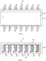
- FIGS. 4 and 5 illustrate top cutaway and end cutaways views respectively, of an alternative embodiment of a melting vessel 14 comprising a plurality of electrodes, wherein a first set of electrodes 148 extend through a sidewall 142 of the melting vessel 14 and a second set of electrodes 147 extending through the floor 144 of the melting vessel 14 .
- each electrode comprises an elongated body that extends a predetermined distance into an interior chamber of the melting vessel 14 .
- the second set of electrodes extend from a position on the floor 144 that is a predetermined distance away from the at least one sidewall 142 .
- each of first set of electrodes 148 extends at an angle (a) relative to a plane (P) parallel to the floor 144 .
- Angle (a) may, for example, range from about 0 degrees to about 75 degrees, such as from about 10 degrees to about 60 degrees, and further such as from about 20 degrees to about 45 degrees.
- electrodes 147 and/or 148 may have a substantially cylindrical shape with a substantially circular or elliptical cross-section. Other cross sections, such as square, rectangular, and triangular are also possible.
- the diameter of electrodes 147 and/or 148 may, for example, range from about 1 to 5 inches, such as from about 2 to 4 inches, including about 3 inches.
- electrodes 147 and/or 148 may be comprised of any electrically conductive material with refractive properties that also show suitable corrosion resistance to high temperature glass melts.
- Exemplary electrode materials include, but are not limited to, at least one material selected from the group consisting of tin, molybdenum, platinum, and alloys and oxides of the same.
- the second set of electrodes 147 can extend upward from a position on the floor at least about 60%, such as at least about 65%, and further such as at least about 70%, including from about 60% to about 75% of the depth of the glass melt.
- Such electrodes may also, for example, extend a distance away from the closest sidewall that is at least about 5%, such as at least about 10%, and further such as at least about 15%, such as from about 5% to about 20% of the width of the melting vessel 142 .
- the portion of electrodes 147 and 148 that extend the farthest into the glass melt are at about the same approximate height in the glass melt and at about the same approximate distance from the nearest sidewall, it is to be understood that embodiments disclosed herein are not so limited and also include those in which the portion of electrodes 147 that extend the farthest into the glass melt may be at a higher or lower height in the glass melt and/or closer or farther distance from the nearest sidewall as compared to the portion of electrodes 148 that extend the farthest into the glass melt. It is to be further understood, that, in certain embodiments, individual electrodes 147 may be of differing heights, diameters, and/or distances from the nearest sidewall. In addition, in certain embodiments, individual electrodes 148 may extend different distances into the glass melt, extend at different angles relative to a plane parallel to the floor 144 , and/or have different diameters.
- FIGS. 4 and 5 show a melting vessel 14 comprising two opposing sidewalls 142 , each opposing sidewall 142 comprising twelve electrodes 148 extending there through and a floor 144 comprising twenty four electrodes 147 extending there through in an alternating arrangement relative to electrodes 148
- embodiments disclosed herein may include other arrangements, including those in which two opposing sidewalls and floor each have any number of electrodes extending there through, such as at least one electrode, at least two electrodes, at least three electrodes, and so forth, extending through each opposing sidewall and/or floor, including from 1 to 100 electrodes extending through each opposing sidewall and/or floor, such as from 2 to 50 electrodes, and further such as from 5 to 20 electrodes extending through each opposing sidewall and/or floor.
- each opposing sidewall and/or floor may have N electrodes extending there through, wherein the closest distance between electrodes ranges from, for example, about 1% to about 20%, such as from about 2% to about 15%, and further such as about 3% to about 10%, and yet further such as about 4% to about 8%, including about 5% of the length of the melting vessel.
- Embodiments disclosed herein may be used with a variety of glass compositions, including those having relatively higher or lower electrical resistivities.
- Such compositions may, for example, include a glass composition, such as an alkali free glass composition comprising 58-65 wt % SiO 2 , 14-20 wt % Al 2 O 3 , 8-12 wt % B 2 O 3 , 1-3 wt % MgO, 5-10 wt % CaO, and 0.5-2 wt % SrO.
- Such compositions may also include a glass composition, such as an alkali free glass composition, comprising 58-65 wt % SiO 2 , 16-22 wt % Al 2 O 3 , 1-5 wt % B 2 O 3 , 1-4 wt % MgO, 2-6 wt % CaO, 1-4 wt % SrO, and 5-10 wt % BaO.
- a glass composition such as an alkali free glass composition, comprising 58-65 wt % SiO 2 , 16-22 wt % Al 2 O 3 , 1-5 wt % B 2 O 3 , 1-4 wt % MgO, 2-6 wt % CaO, 1-4 wt % SrO, and 5-10 wt % BaO.
- Such compositions may further include a glass composition, such as an alkali free glass composition, comprising 57-61 wt % SiO 2 , 17-21 wt % Al 2 O 3 , 5-8 wt % B 2 O 3 , 1-5 wt % MgO, 3-9 wt % CaO, 0-6 wt % SrO, and 0-7 wt % BaO.
- a glass composition such as an alkali free glass composition, comprising 57-61 wt % SiO 2 , 17-21 wt % Al 2 O 3 , 5-8 wt % B 2 O 3 , 1-5 wt % MgO, 3-9 wt % CaO, 0-6 wt % SrO, and 0-7 wt % BaO.
- Such compositions may additionally include a glass composition, such as an alkali containing glass composition, comprising 55-72 wt % SiO 2 , 12-24 wt % Al 2 O 3 , 10-18 wt % Na 2 O, 0-10 wt % B 2 O 3 , 0-5 wt % K 2 O, 0-5 wt % MgO, and 0-5 wt % CaO, which, in certain embodiments, may also include 1-5 wt % K 2 O and 1-5 wt % MgO.
- a glass composition such as an alkali containing glass composition, comprising 55-72 wt % SiO 2 , 12-24 wt % Al 2 O 3 , 10-18 wt % Na 2 O, 0-10 wt % B 2 O 3 , 0-5 wt % K 2 O, 0-5 wt % MgO, and 0-5 wt % CaO, which, in certain embodiment
- Embodiments disclosed herein can be used in the production of glass articles, such as glass sheets used in electronic devices, including electronic devices with high resolution displays, such as televisions, tablets, and smart phones.
- a glass melt can be heated at an average temperature of at least about 1600° C. without exceeding a breakdown condition of the refractory material in contact with the glass melt.
- modeling experiments conducted by applicants have suggested that at glass and refractory temperatures of at least about 1600° C., such when the glass comprises any of the above compositions and the refractory comprises zirconia, configuration of the electrodes and melting vessel geometry substantially affects the amount of power generated within the refractory material at the glass melt interface relative to the power generated within the glass melt.
- Embodiments disclosed herein including the electrode configurations and melting vessel geometries disclosed herein, provide a solution to this problem and can reduce the amount of power generated within the refractory by at least 30% relative to alternative configurations and geometries. Embodiments disclosed herein can also enable more flexible melt system operation, wherein different glass compositions having different electrical resistivities and different temperature regimes can be utilized without the need to change the melt system configuration.
Landscapes
- Chemical & Material Sciences (AREA)
- Engineering & Computer Science (AREA)
- Materials Engineering (AREA)
- Organic Chemistry (AREA)
- Chemical Kinetics & Catalysis (AREA)
- Electrochemistry (AREA)
- Glass Melting And Manufacturing (AREA)
- Glass Compositions (AREA)
Priority Applications (1)
| Application Number | Priority Date | Filing Date | Title |
|---|---|---|---|
| US16/348,142 US11028001B2 (en) | 2016-11-08 | 2017-11-07 | High temperature glass melting vessel |
Applications Claiming Priority (3)
| Application Number | Priority Date | Filing Date | Title |
|---|---|---|---|
| US201662419133P | 2016-11-08 | 2016-11-08 | |
| PCT/US2017/060474 WO2018089387A1 (en) | 2016-11-08 | 2017-11-07 | High temperature glass melting vessel |
| US16/348,142 US11028001B2 (en) | 2016-11-08 | 2017-11-07 | High temperature glass melting vessel |
Publications (2)
| Publication Number | Publication Date |
|---|---|
| US20190276346A1 US20190276346A1 (en) | 2019-09-12 |
| US11028001B2 true US11028001B2 (en) | 2021-06-08 |
Family
ID=62109380
Family Applications (1)
| Application Number | Title | Priority Date | Filing Date |
|---|---|---|---|
| US16/348,142 Active 2038-02-11 US11028001B2 (en) | 2016-11-08 | 2017-11-07 | High temperature glass melting vessel |
Country Status (6)
| Country | Link |
|---|---|
| US (1) | US11028001B2 (enExample) |
| JP (1) | JP7105794B2 (enExample) |
| KR (1) | KR102412297B1 (enExample) |
| CN (1) | CN109923077B (enExample) |
| TW (1) | TWI756290B (enExample) |
| WO (1) | WO2018089387A1 (enExample) |
Cited By (1)
| Publication number | Priority date | Publication date | Assignee | Title |
|---|---|---|---|---|
| US12157696B2 (en) | 2019-11-21 | 2024-12-03 | Schott Ag | Method for heating molten glass and glass article |
Families Citing this family (2)
| Publication number | Priority date | Publication date | Assignee | Title |
|---|---|---|---|---|
| CN115385553A (zh) * | 2022-07-28 | 2022-11-25 | 陕西彩虹工业智能科技有限公司 | 一种微晶玻璃的熔炼装置 |
| CN117142747A (zh) * | 2023-09-04 | 2023-12-01 | 彩虹显示器件股份有限公司 | 高世代大吨位基板玻璃窑炉电加热装置及方法 |
Citations (19)
| Publication number | Priority date | Publication date | Assignee | Title |
|---|---|---|---|---|
| US2267537A (en) * | 1939-07-17 | 1941-12-23 | Saint Gobain | Electric furnace |
| US2523030A (en) * | 1948-10-30 | 1950-09-19 | Glass Fibers Inc | Electric glass furnace |
| US3530221A (en) | 1968-05-01 | 1970-09-22 | Penberthy Harvey Larry | Ac/dc electrode and power supply system for a glass furnace |
| GB1281424A (en) | 1970-06-08 | 1972-07-12 | Harvey Larry Penberthy | Ac/dc electrode and power supply system for a glass furnace |
| US3941577A (en) * | 1974-11-29 | 1976-03-02 | Ppg Industries, Inc. | Method and apparatus for making molten glass |
| US4143232A (en) * | 1976-11-01 | 1979-03-06 | Corning Glass Works | Furnace having different electrode immersions to control convection currents, the shape, elevation and stability of the fusion zone |
| US5283803A (en) | 1992-06-01 | 1994-02-01 | Glass Incorporated International | Electrode assembly for glass melting furnace |
| US20080057275A1 (en) | 2006-08-31 | 2008-03-06 | Paul Richard Grzesik | Method and apparatus for minimizing oxidation pitting of refractory metal vessels |
| US20080076659A1 (en) | 2006-02-24 | 2008-03-27 | Saint-Gobain Centre De Recherches Et D'etudes Europeen | High resistivity refractory with a high zirconia content |
| CN101408231A (zh) | 2007-10-10 | 2009-04-15 | Valeo离合器公司 | 离合器机构,尤其是用于机动车辆的离合器机构 |
| US20100122555A1 (en) | 2008-11-18 | 2010-05-20 | David Myron Lineman | Platinum condensation abatement by electrostatic precipitation |
| CN102807307A (zh) | 2011-05-31 | 2012-12-05 | 康宁股份有限公司 | 玻璃熔体处理装备和方法 |
| US8341978B2 (en) | 2005-11-04 | 2013-01-01 | Ocv Intellectual Capital, Llc | Method of manufacturing high performance glass fibers in a refractory lined melter and fiber formed thereby |
| WO2014036979A1 (en) | 2012-09-05 | 2014-03-13 | Vysoká škola chemicko-technologická v Praze | Method for continuous glass melting under controlled convection of glass melt and glass melting furnace for making the same |
| US20140144183A1 (en) * | 2012-11-28 | 2014-05-29 | Memduh Demirbas | Glass manufacturing apparatus and methods |
| US20140196504A1 (en) * | 2011-07-22 | 2014-07-17 | Saint-Gobain Centre De Recherches Et D'etudes Europeen | Refractory block and glass-melting furnace |
| US8869564B2 (en) | 2006-01-24 | 2014-10-28 | Schott Ag | Method for temperature manipulation of a melt |
| CN204474521U (zh) | 2015-04-01 | 2015-07-15 | 秦皇岛弘华特种玻璃有限公司 | 熔化硼硅玻璃的全电熔窑 |
| CN105776819A (zh) | 2016-04-27 | 2016-07-20 | 巨石集团有限公司 | 一种具有高熔化率的玻璃池窑 |
Family Cites Families (4)
| Publication number | Priority date | Publication date | Assignee | Title |
|---|---|---|---|---|
| DE19924521C2 (de) | 1999-05-28 | 2003-04-30 | Schott Glas | Verfahren zum Schmelzen von Glas |
| WO2004052053A1 (de) | 2002-12-03 | 2004-06-17 | Schott Ag | Heizvorrichtung mit elektrode zur konduktiven beheizung von schmelzen |
| DE102006003534A1 (de) | 2006-01-24 | 2007-08-02 | Schott Ag | Verfahren und Vorrichtung zum Korrosionsschutz von Elektroden bei der Temperaturbeeinflussung einer Schmelze |
| US8973406B2 (en) * | 2012-10-26 | 2015-03-10 | Corning Incorporated | Melters for glass forming apparatuses |
-
2017
- 2017-11-07 US US16/348,142 patent/US11028001B2/en active Active
- 2017-11-07 JP JP2019545888A patent/JP7105794B2/ja active Active
- 2017-11-07 WO PCT/US2017/060474 patent/WO2018089387A1/en not_active Ceased
- 2017-11-07 KR KR1020197016113A patent/KR102412297B1/ko active Active
- 2017-11-07 CN CN201780069113.9A patent/CN109923077B/zh active Active
- 2017-11-08 TW TW106138590A patent/TWI756290B/zh active
Patent Citations (23)
| Publication number | Priority date | Publication date | Assignee | Title |
|---|---|---|---|---|
| US2267537A (en) * | 1939-07-17 | 1941-12-23 | Saint Gobain | Electric furnace |
| US2523030A (en) * | 1948-10-30 | 1950-09-19 | Glass Fibers Inc | Electric glass furnace |
| US3530221A (en) | 1968-05-01 | 1970-09-22 | Penberthy Harvey Larry | Ac/dc electrode and power supply system for a glass furnace |
| GB1281424A (en) | 1970-06-08 | 1972-07-12 | Harvey Larry Penberthy | Ac/dc electrode and power supply system for a glass furnace |
| US3941577A (en) * | 1974-11-29 | 1976-03-02 | Ppg Industries, Inc. | Method and apparatus for making molten glass |
| US4143232A (en) * | 1976-11-01 | 1979-03-06 | Corning Glass Works | Furnace having different electrode immersions to control convection currents, the shape, elevation and stability of the fusion zone |
| US5283803A (en) | 1992-06-01 | 1994-02-01 | Glass Incorporated International | Electrode assembly for glass melting furnace |
| US8341978B2 (en) | 2005-11-04 | 2013-01-01 | Ocv Intellectual Capital, Llc | Method of manufacturing high performance glass fibers in a refractory lined melter and fiber formed thereby |
| US8869564B2 (en) | 2006-01-24 | 2014-10-28 | Schott Ag | Method for temperature manipulation of a melt |
| US7655587B2 (en) | 2006-02-24 | 2010-02-02 | Saint-Gobain Centre De Recherches Et D'etudes Europeen | High resistivity refractory with a high zirconia content |
| US20080076659A1 (en) | 2006-02-24 | 2008-03-27 | Saint-Gobain Centre De Recherches Et D'etudes Europeen | High resistivity refractory with a high zirconia content |
| US7687422B2 (en) | 2006-02-24 | 2010-03-30 | Saint-Gobain Centre De Recherches Et D'etudes European | High resistivity refractory with a high zirconia content |
| CN101668875A (zh) | 2006-08-31 | 2010-03-10 | 康宁股份有限公司 | 用于贵金属玻璃输送系统的热喷涂的高熔点氧化物涂层 |
| US20080057275A1 (en) | 2006-08-31 | 2008-03-06 | Paul Richard Grzesik | Method and apparatus for minimizing oxidation pitting of refractory metal vessels |
| CN101408231A (zh) | 2007-10-10 | 2009-04-15 | Valeo离合器公司 | 离合器机构,尤其是用于机动车辆的离合器机构 |
| US20100122555A1 (en) | 2008-11-18 | 2010-05-20 | David Myron Lineman | Platinum condensation abatement by electrostatic precipitation |
| CN102256906A (zh) | 2008-11-18 | 2011-11-23 | 康宁股份有限公司 | 通过静电除尘的铂凝结减少 |
| CN102807307A (zh) | 2011-05-31 | 2012-12-05 | 康宁股份有限公司 | 玻璃熔体处理装备和方法 |
| US20140196504A1 (en) * | 2011-07-22 | 2014-07-17 | Saint-Gobain Centre De Recherches Et D'etudes Europeen | Refractory block and glass-melting furnace |
| WO2014036979A1 (en) | 2012-09-05 | 2014-03-13 | Vysoká škola chemicko-technologická v Praze | Method for continuous glass melting under controlled convection of glass melt and glass melting furnace for making the same |
| US20140144183A1 (en) * | 2012-11-28 | 2014-05-29 | Memduh Demirbas | Glass manufacturing apparatus and methods |
| CN204474521U (zh) | 2015-04-01 | 2015-07-15 | 秦皇岛弘华特种玻璃有限公司 | 熔化硼硅玻璃的全电熔窑 |
| CN105776819A (zh) | 2016-04-27 | 2016-07-20 | 巨石集团有限公司 | 一种具有高熔化率的玻璃池窑 |
Non-Patent Citations (4)
| Title |
|---|
| Chinese Patent Application No. 201780069113.9, Office Action dated Mar. 17, 2021, 13 pages (6 pages of English Translation and 7 pages of Original Document). |
| International Search Report and Written Opinion of the International Searching Authority; PCT/US2017/060474; dated Jan. 26, 2018; 9 Pages; ISA/US Commissioner for Patents. |
| J. Stanek; "Electric Melting of Glass: Glass Science and Technology 1" ; Elsevier Scientific Publishing Company, (1977) p. 358. |
| Pincus et al; "Electric Melting in the Glass Industry"; Ch. 8 Electrical Glass Melting, New York: Books for Industry and the Glass Industry Magazine, p. 27, (1966. |
Cited By (1)
| Publication number | Priority date | Publication date | Assignee | Title |
|---|---|---|---|---|
| US12157696B2 (en) | 2019-11-21 | 2024-12-03 | Schott Ag | Method for heating molten glass and glass article |
Also Published As
| Publication number | Publication date |
|---|---|
| KR20190078620A (ko) | 2019-07-04 |
| JP7105794B2 (ja) | 2022-07-25 |
| US20190276346A1 (en) | 2019-09-12 |
| TW201825414A (zh) | 2018-07-16 |
| CN109923077B (zh) | 2022-05-13 |
| CN109923077A (zh) | 2019-06-21 |
| JP2019534237A (ja) | 2019-11-28 |
| KR102412297B1 (ko) | 2022-06-24 |
| WO2018089387A1 (en) | 2018-05-17 |
| TWI756290B (zh) | 2022-03-01 |
Similar Documents
| Publication | Publication Date | Title |
|---|---|---|
| US11512015B2 (en) | Method and apparatus for glass ribbon thermal control | |
| US11028001B2 (en) | High temperature glass melting vessel | |
| US20250164187A1 (en) | Glass melting furnaces and vessels with improved thermal performance | |
| US11130696B2 (en) | Methods for reconditioning glass manufacturing systems | |
| WO2017223034A1 (en) | Apparatus and method for glass delivery orientation | |
| WO2019018670A1 (en) | METHOD AND APPARATUS FOR HEAT TRANSFER OF ADJUSTABLE GLASS TAPE | |
| CN113165928B (zh) | 用于在玻璃制作工艺中减轻贵金属部件的电化学腐蚀的装置和方法 | |
| KR102932346B1 (ko) | 유리 제조 장치 | |
| US20240391816A1 (en) | Glass manufacturing apparatus with leak mitigation features | |
| CN113015706B (zh) | 用于在玻璃制作工艺中减轻对贵金属部件的电化学腐蚀的装置和方法 | |
| US20250115508A1 (en) | Glass melting furnaces and vessels with improved electrical resistivity | |
| KR102700028B1 (ko) | 내식성이 개선된 도관 가열 장치 및 방법 | |
| WO2018081664A1 (en) | Liquid metal viscosity control of molten glass | |
| WO2024091384A1 (en) | Apparatus and method for manufacturing a glass article | |
| WO2024177807A1 (en) | Apparatus and method for controlling glass ribbon characteristics |
Legal Events
| Date | Code | Title | Description |
|---|---|---|---|
| AS | Assignment |
Owner name: CORNING INCORPORATED, NEW YORK Free format text: ASSIGNMENT OF ASSIGNORS INTEREST;ASSIGNORS:DE ANGELIS, GILBERT;DELAMIELLEURE, MEGAN AURORA;PETERS, GUIDO;SIGNING DATES FROM 20190502 TO 20190503;REEL/FRAME:049106/0853 |
|
| FEPP | Fee payment procedure |
Free format text: ENTITY STATUS SET TO UNDISCOUNTED (ORIGINAL EVENT CODE: BIG.); ENTITY STATUS OF PATENT OWNER: LARGE ENTITY |
|
| STPP | Information on status: patent application and granting procedure in general |
Free format text: DOCKETED NEW CASE - READY FOR EXAMINATION |
|
| STPP | Information on status: patent application and granting procedure in general |
Free format text: NON FINAL ACTION MAILED |
|
| STPP | Information on status: patent application and granting procedure in general |
Free format text: NOTICE OF ALLOWANCE MAILED -- APPLICATION RECEIVED IN OFFICE OF PUBLICATIONS |
|
| STPP | Information on status: patent application and granting procedure in general |
Free format text: AWAITING TC RESP, ISSUE FEE PAYMENT RECEIVED |
|
| STPP | Information on status: patent application and granting procedure in general |
Free format text: PUBLICATIONS -- ISSUE FEE PAYMENT VERIFIED |
|
| STCF | Information on status: patent grant |
Free format text: PATENTED CASE |
|
| CC | Certificate of correction | ||
| MAFP | Maintenance fee payment |
Free format text: PAYMENT OF MAINTENANCE FEE, 4TH YEAR, LARGE ENTITY (ORIGINAL EVENT CODE: M1551); ENTITY STATUS OF PATENT OWNER: LARGE ENTITY Year of fee payment: 4 |