US11001378B2 - Configuration for vertical take-off and landing system for aerial vehicles - Google Patents
Configuration for vertical take-off and landing system for aerial vehicles Download PDFInfo
- Publication number
- US11001378B2 US11001378B2 US16/020,802 US201816020802A US11001378B2 US 11001378 B2 US11001378 B2 US 11001378B2 US 201816020802 A US201816020802 A US 201816020802A US 11001378 B2 US11001378 B2 US 11001378B2
- Authority
- US
- United States
- Prior art keywords
- vehicle
- fore
- tail
- ejectors
- coupled
- Prior art date
- Legal status (The legal status is an assumption and is not a legal conclusion. Google has not performed a legal analysis and makes no representation as to the accuracy of the status listed.)
- Active, expires
Links
Images


Classifications
-
- B—PERFORMING OPERATIONS; TRANSPORTING
- B64—AIRCRAFT; AVIATION; COSMONAUTICS
- B64C—AEROPLANES; HELICOPTERS
- B64C29/00—Aircraft capable of landing or taking-off vertically, e.g. vertical take-off and landing [VTOL] aircraft
- B64C29/0008—Aircraft capable of landing or taking-off vertically, e.g. vertical take-off and landing [VTOL] aircraft having its flight directional axis horizontal when grounded
- B64C29/0041—Aircraft capable of landing or taking-off vertically, e.g. vertical take-off and landing [VTOL] aircraft having its flight directional axis horizontal when grounded the lift during taking-off being created by jet motors
- B64C29/005—Aircraft capable of landing or taking-off vertically, e.g. vertical take-off and landing [VTOL] aircraft having its flight directional axis horizontal when grounded the lift during taking-off being created by jet motors the motors being fixed relative to the fuselage
-
- B—PERFORMING OPERATIONS; TRANSPORTING
- B64—AIRCRAFT; AVIATION; COSMONAUTICS
- B64C—AEROPLANES; HELICOPTERS
- B64C15/00—Attitude, flight direction, or altitude control by jet reaction
- B64C15/02—Attitude, flight direction, or altitude control by jet reaction the jets being propulsion jets
-
- B—PERFORMING OPERATIONS; TRANSPORTING
- B64—AIRCRAFT; AVIATION; COSMONAUTICS
- B64C—AEROPLANES; HELICOPTERS
- B64C29/00—Aircraft capable of landing or taking-off vertically, e.g. vertical take-off and landing [VTOL] aircraft
- B64C29/0008—Aircraft capable of landing or taking-off vertically, e.g. vertical take-off and landing [VTOL] aircraft having its flight directional axis horizontal when grounded
- B64C29/0041—Aircraft capable of landing or taking-off vertically, e.g. vertical take-off and landing [VTOL] aircraft having its flight directional axis horizontal when grounded the lift during taking-off being created by jet motors
- B64C29/0066—Aircraft capable of landing or taking-off vertically, e.g. vertical take-off and landing [VTOL] aircraft having its flight directional axis horizontal when grounded the lift during taking-off being created by jet motors with horizontal jet and jet deflector
-
- B—PERFORMING OPERATIONS; TRANSPORTING
- B64—AIRCRAFT; AVIATION; COSMONAUTICS
- B64C—AEROPLANES; HELICOPTERS
- B64C3/00—Wings
- B64C3/10—Shape of wings
- B64C3/16—Frontal aspect
-
- B—PERFORMING OPERATIONS; TRANSPORTING
- B64—AIRCRAFT; AVIATION; COSMONAUTICS
- B64C—AEROPLANES; HELICOPTERS
- B64C39/00—Aircraft not otherwise provided for
- B64C39/06—Aircraft not otherwise provided for having disc- or ring-shaped wings
- B64C39/066—Aircraft not otherwise provided for having disc- or ring-shaped wings having channel wings
-
- B—PERFORMING OPERATIONS; TRANSPORTING
- B64—AIRCRAFT; AVIATION; COSMONAUTICS
- B64C—AEROPLANES; HELICOPTERS
- B64C39/00—Aircraft not otherwise provided for
- B64C39/06—Aircraft not otherwise provided for having disc- or ring-shaped wings
- B64C39/068—Aircraft not otherwise provided for having disc- or ring-shaped wings having multiple wings joined at the tips
-
- B—PERFORMING OPERATIONS; TRANSPORTING
- B64—AIRCRAFT; AVIATION; COSMONAUTICS
- B64C—AEROPLANES; HELICOPTERS
- B64C39/00—Aircraft not otherwise provided for
- B64C39/12—Canard-type aircraft
-
- B—PERFORMING OPERATIONS; TRANSPORTING
- B64—AIRCRAFT; AVIATION; COSMONAUTICS
- B64D—EQUIPMENT FOR FITTING IN OR TO AIRCRAFT; FLIGHT SUITS; PARACHUTES; ARRANGEMENTS OR MOUNTING OF POWER PLANTS OR PROPULSION TRANSMISSIONS IN AIRCRAFT
- B64D27/00—Arrangement or mounting of power plant in aircraft; Aircraft characterised thereby
- B64D27/02—Aircraft characterised by the type or position of power plant
- B64D27/16—Aircraft characterised by the type or position of power plant of jet type
- B64D27/18—Aircraft characterised by the type or position of power plant of jet type within or attached to wing
-
- B—PERFORMING OPERATIONS; TRANSPORTING
- B64—AIRCRAFT; AVIATION; COSMONAUTICS
- B64D—EQUIPMENT FOR FITTING IN OR TO AIRCRAFT; FLIGHT SUITS; PARACHUTES; ARRANGEMENTS OR MOUNTING OF POWER PLANTS OR PROPULSION TRANSMISSIONS IN AIRCRAFT
- B64D33/00—Arrangements in aircraft of power plant parts or auxiliaries not otherwise provided for
- B64D33/04—Arrangements in aircraft of power plant parts or auxiliaries not otherwise provided for of exhaust outlets or jet pipes
-
- Y—GENERAL TAGGING OF NEW TECHNOLOGICAL DEVELOPMENTS; GENERAL TAGGING OF CROSS-SECTIONAL TECHNOLOGIES SPANNING OVER SEVERAL SECTIONS OF THE IPC; TECHNICAL SUBJECTS COVERED BY FORMER USPC CROSS-REFERENCE ART COLLECTIONS [XRACs] AND DIGESTS
- Y02—TECHNOLOGIES OR APPLICATIONS FOR MITIGATION OR ADAPTATION AGAINST CLIMATE CHANGE
- Y02T—CLIMATE CHANGE MITIGATION TECHNOLOGIES RELATED TO TRANSPORTATION
- Y02T50/00—Aeronautics or air transport
- Y02T50/10—Drag reduction
-
- Y—GENERAL TAGGING OF NEW TECHNOLOGICAL DEVELOPMENTS; GENERAL TAGGING OF CROSS-SECTIONAL TECHNOLOGIES SPANNING OVER SEVERAL SECTIONS OF THE IPC; TECHNICAL SUBJECTS COVERED BY FORMER USPC CROSS-REFERENCE ART COLLECTIONS [XRACs] AND DIGESTS
- Y02—TECHNOLOGIES OR APPLICATIONS FOR MITIGATION OR ADAPTATION AGAINST CLIMATE CHANGE
- Y02T—CLIMATE CHANGE MITIGATION TECHNOLOGIES RELATED TO TRANSPORTATION
- Y02T50/00—Aeronautics or air transport
- Y02T50/40—Weight reduction
Definitions
- 15/686,052 is also a continuation-in-part of application Ser. No. 15/256,178, filed Sep. 2, 2016; which claims the benefit of 62/213,465, filed Sep. 2, 2015; application Ser. No. 15/686,052 is also a continuation-in-part of Application No. PCT/US2016/050236, filed Sep. 2, 2016; which claims the benefit of Provisional Application No. 62/213,465, filed Sep. 2, 2015.
- 15/670,943 is also a continuation-in-part of Application No. PCT/US2016/064827 filed Dec. 2, 2016; which claims the benefit of Provisional Application No. 62/263,407 filed Dec. 4, 2015; application Ser. No. 15/670,943 is also a continuation-in-part of application Ser. No. 15/456,450, filed Mar. 10, 2017; which claims the benefit of Provisional Application No. 62/307,318, filed Mar. 11, 2016; application Ser. No. 15/456,450 is also a continuation-in-part of Ser. No. 15/256,178, filed Sep. 2, 2016; which claims the benefit of Provisional Application No. 62/213,465, filed Sep. 2, 2015; application Ser. No.
- 15/670,943 is also a continuation-in-part of Application No. PCT/US2017/021975, filed Mar. 10, 2017; which claims the benefit of Provisional Application No. 62/307,318, filed Mar. 11, 2016; application Ser. No. 15/670,943 is also a continuation-in-part of application Ser. No. 15/221,389, filed Jul. 27, 2016; which claims the benefit of Provisional Application No. 62/213,465, filed Sep. 2, 2015; application Ser. No. 15/670,943 is also a continuation-in-part of Application No. PCT/US2016/044327, filed Jul. 27, 2016; which claims the benefit of Provisional Application No. 62/213,465, filed Sep. 2, 2015; application Ser. No.
- 15/670,943 is also a continuation-in-part of application Ser. No. 15/221,389 filed Jul. 27, 2016; which claims the benefit of Provisional Application No. 62/213,465 filed Sep. 2, 2015; application Ser. No. 15/670,943 is also a continuation-in-part of application Ser. No. 15/221,439, filed Jul. 27, 2016, which claims the benefit of Provisional Application No. 62/213,465, filed Sep. 2, 2015; application Ser. No. 15/670,943 is also a continuation-in-part of Application No. PCT/US2016/044326, filed Jul. 27, 2016; which claims the benefit of Provisional Application No. 62/213,465, filed Sep. 2, 2015; application Ser. No.
- 15/670,943 is also a continuation-in-part of application Ser. No. 15/256,178, filed Sep. 2, 2016; which claims the benefit of Provisional Application No. 62/213,465, filed Sep. 2, 2015; application Ser. No. 15/670,943 is also a continuation-in-part of Application No. PCT/US2016/050236, filed Sep. 2, 2016; which claims the benefit of Provisional Application No. 62/213,465, filed Sep. 2, 2015.
- Balance is one of the most important drivers for the design of a VTOL aircraft.
- the thrust has to be distributed around the aircraft, and moments are balanced around the center of mass, in order for the aircraft to remain balanced.
- the aircraft cannot be balanced if the source of the thrust is in only one location.
- the aircraft needs to employ several thrust generating elements in locations specifically chosen in order to cancel out the moments at all times (calculated as force (thrust) ⁇ moment arm around the center of the aircraft mass). This is difficult to achieve if the majority of the thrust is located, for instance, in the rear portion of the aircraft (as typically found in a VTOL aircraft).
- FIG. 1 illustrates a top view of an embodiment of the present invention
- FIG. 2 is a rear view of the embodiment of the present invention shown in FIG. 1 ;
- FIG. 3 is a front view of the embodiment of the present invention shown in FIG. 1 ;
- FIG. 4 illustrates an alternative embodiment of the present invention in an exploded isometric view
- FIG. 5 illustrates an alternative embodiment of the present invention in rear perspective view
- FIGS. 6A-6D illustrate the progression of an embodiment of the present invention from take-off to level flight relative to a landing/takeoff surface
- FIG. 7 illustrates the upper half of a turboshaft/turboprop engine with highlights of the stations of the flow according to an embodiment of the present invention
- FIG. 8 illustrates one embodiment of the present invention in a top view.
- FIG. 9 is a side cross-sectional view of the embodiment shown in FIG. 8 .
- FIG. 10 is a front view of the embodiment shown in FIG. 8 .
- FIG. 11 is a rear view of the embodiment shown in FIG. 8 .
- FIG. 12 is a top view of an alternative embodiment of the present invention.
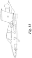
- FIG. 13 is a side cross-sectional view of the embodiment shown in FIG. 12 .
- FIG. 14 is a front view of the embodiment shown in FIG. 12 .
- FIG. 15 is a side cross-sectional view of the embodiment shown in FIG. 8 during the take off to cruise transition.
- FIG. 16 illustrates the cruise position of the embodiment shown in FIG. 8 .
- the present application relates generally to thrust augmentation for unmanned aerial vehicles.
- one or more embodiments of the present invention disclosed in this application provide unique solutions to the challenges of vertical take-off and landing (VTOL) and short take-off and landing (STOL) aircrafts.
- VTOL vertical take-off and landing
- STOL short take-off and landing
- the terms “Tailsitter” and “Flying Vehicle” may refer to one or more embodiments of the present invention.
- An embodiment of the present invention addresses the issue of thrust-to-weight ratio and sizing of the engine through enhancing and augmenting the thrust.
- the ejectors/thrusters themselves are designed to allow for augmentation exceeding 2:1 and close to 3:1. This means that these thrusters are designed to produce a thrust that is 2-3 times greater than the thrust produced by a conventional turbojet.
- Thrust augmentation designs are disclosed in U.S. patent application Ser. No. 15/221,389, entitled FLUIDIC PROPULSIVE SYSTEM, filed Jul. 27, 2016 (“the '389 application”) and U.S. patent application Ser. No. 15/256,178 filed Sep.
- thrusters shall refer to such ejectors/thrusters with significant augmentation that are described in the '389 application as well as any subsequent versions or improvements thereof.
- the Thruster is used with a gas generator as a source for primary flows. While it is not necessary to utilize such a Thruster with a gas generator that supplies the primary flow in the present invention, utilizing such a Thruster can enhance the effects of thrust augmentation.
- Thrusters and the shroud can have a combined effect of thrust augmentation of, for example, 1.1 (from shrouded thrusters) times 2.5 (from Thrusters) augmentation, which results in a total augmentation of 2.75. Therefore, such a system can produce a thrust that is equal to the weight of the aircraft at takeoff by augmenting an otherwise ⁇ 2.75 thrust generated by a simple turbojet.
- Thrust reduction via throttle reduction may adjust the power needed to overcome the drag of the aircraft, which may also mean a lesser augmentation of the entire system and sufficient to propel the aircraft forward and maintain its speed.
- a 150-lbs aircraft may employ a 75-lbf turbojet adapted to become a gas generator.
- This concept is disclosed in U.S. Provisional Patent Application 62/263,407, entitled MICRO-TURBINE GAS GENERATOR AND PROPULSIVE SYSTEM, filed Dec. 4, 2015 (“the '407 Provisional Application) and U.S. patent application Ser. No. 15/368,428 filed Dec. 2, 2016 (“the '428 application”).
- the '407 Provisional Application and '428 application are herein incorporated by reference in their entireties.
- these thrust augmenting ejectors can produce an augmentation of, for example, 1.75 times the original, which means 75 multiplied by 1.75, which results in 131.25 lbf augmented thrust.
- the thrust may be limited to this value and may not allow the thrust to lift the aircraft off the ground.
- the overall augmentation of the thrust becomes, for example, e.g., 1.15 multiplied by 131.25, resulting in 150.94 lbf, and hence exceeds the weight of the aircraft and allows for the take-off.
- the accelerations may exceed the current human-limited accelerations that are restricted for human safety and non-life threatening standards. In one embodiment, the accelerations may exceed 20 times the gravitational acceleration. As such, after a short time, the vehicle may have the ability to change its attitude and achieve level flight by throttle and control surface changes. Lift increases as the vehicle changes its attitude, while the combined augmentation also diminishes in value due to the throttle pull back.
- the Tailsitter may then achieve level flight by concomitantly reducing the engine load (ergo gas generator primary stream) to the thrusters in the first level and allowing the boxed wing to produce the proper lift to maintain the attitude, while the thrusters produce enough thrust to overcome drag.
- the attitude of the aircraft can be adjusted with an increase angle of attack and the thrust augmentation again displaces the need for lift, as the forward speed reduces and the aircraft eventually can land vertically, on its tail portion, balanced by the thrusters and its combined augmentation effect.
- One or more embodiments of the present invention are able to overcome the issue of balancing the forces and moments by having smaller moment arms than are needed to balance them around the center of mass, which is achieved by having a distribution of thrust across various locations in the aircraft. This, in turn, allows these embodiments to have more control and makes it easier to maintain a hover/upright position.
- the unique technology allows for the distribution of thrust across various locations of the aircraft, with augmentation levels achieved in various thrusters (e.g., in front, “fore ejectors” behind canard wings, employed at hovering phases take-off and landing and turned off at level flight, and in the back the “tail ejectors” that generate the bulk of the thrust).
- various thrusters e.g., in front, “fore ejectors” behind canard wings, employed at hovering phases take-off and landing and turned off at level flight, and in the back the “tail ejectors” that generate the bulk of the thrust.
- a conventional small ( ⁇ 250 lbf thrust) mini jet engine usually provides thrust at a single location, typically at the center of the exhaust section. Some small turbofans also provide the thrust in a concentrated point on the aircraft.
- One or more embodiments of the present invention allow the distribution of the thrust in a nearly linear and/or non-circular manner, as opposed to a circular manner, and thus distribute the thrust per the length of a wing or other airfoils and/or control surfaces of an aircraft.
- both the main, hot stream and the bleed air portion of the stream from the compressor are used as motive fluids for the augmenting thrusters.
- this embodiment allows the distribution of the thrust in a linear, mainly non-circular and distributed, not at a concentrated point, it achieves better propulsive efficiency of the aircraft.
- the optionally advantageous feature of molding and shaping the thruster according to the shape of the airfoils to obtain better performance e.g., increasing the stall margin of a given canard wing if thruster is placed downstream of it, or augmenting the lift on a main wing if the thruster is placed at an optimal location upstream of said main wing.
- the distributed thrust therefore improves the performance of the aircraft by distributing an otherwise 75 lbf turbojet hot and fast stream from a concentrated location at the back of the turbojet engine to, for example, at least four locations on the aircraft.
- thrusters are mounted at these four locations on the vehicle in an optimal manner, such that they are (i) receiving the pressurized air or gas stream from the compressor bleed system and exhaust of the gas generator respectively and (ii) augmenting each of the four thrust forces that would otherwise result from the simple isentropic expansion of the four primary streams by 1.5-3 times. This also results in an advantageous distributed flow and thrust from the four locations, thus enhancing the aircraft maneuverability and propulsive efficiency.
- An embodiment (a turboprop STOL version) of the present invention includes augmentation of thrust based on motive fluid provided by a bleed system of a gas generator.
- the bleed system provides the port and starboard front thrusters with the motive air from the bleed.
- the front thrusters provide an augmentation corresponding to specific thrust of 100-300 lbf for each lb/sec of motive air provided by the bleed system. This value exceeds by far the typical 50-65 lbf/lb/sec specific thrust obtained with small turbojet engines, due to limited efficiencies of the components and lack of advanced technologies.
- the value of the compressed air is utilized by employing the thrusters in front and back of the system resulting in augmentation ratios of over 2:1. As such, more thrust can be obtained from the same energy input.
- a control valve is employed to provide the balance of flow between the port and starboard thrusters.
- the modulation of the air can be obtained with valves placed between the engine bleed and the control valve box.
- the valves allow for control of the flow on each thruster and/or balance of the flow of the motive air between the two front thrusters by opening or closing a passage to one or both of the front thrusters and changing the motive fluid supply. This, in turn, generates an imbalance in thrust, and the imbalance results in the change in the aircraft attitude.
- the thrusters can also be swiveled around their main axis, while being modulated for primary flow (motive fluid flow) at the same time. This allows for control on the pitch and roll as well as some limited control on the yaw, and combinations thereof.
- thrusters are supplied a high pressure hot stream of exhaust gas delivered by the generator (minus the bleed air) via a transition piece or conduit.
- the transition piece connects the exhaust of the gas generator to the said rear thrusters.
- Thrusters use this delivery as a motive air to augment the thrust.
- This jet augmenting system is specifically designed to allow fast movement of the vehicle at the cost of additional fuel consumption, resulting in airspeeds of the vehicle exceeding 200 MPH and propulsive efficiencies of close to 80-90%.
- the system results in a typical specific fuel consumption of 0.8-1.1 lb/hr of fuel per lbf generated, which is typical of the low by-pass fans, but without a fan or turbine driving the fan.
- the system can also achieve the performance of specific fuel consumption of a low-bypass turbofan at much smaller scale and without employing a free turbine and a fan, per se, reducing thus the weight and complexity of the entire propulsion system and eliminating a large, moving assembly such as the fan/free turbine assembly.
- the rear section of the propulsive system can be made flexible enough to be replaced by a turbine/propeller system while keeping the common, identical gas generator (front of the propulsive system) and augmenting “cold” thrusters.
- the turbine will receive the same flow as in the case of the jet augmenting system, but can extract the energy from the gas generator exhaust flow and turn it into mechanical work used to rotate the propeller rather than fluidically augment the flow in an ejector type thruster.
- the interfaces are very similar, the replacement consisting of the removal of the transition piece conduit with a conduit that guides the hot, pressurized gases towards the free turbine driving the propeller, after which the exhaust gases are expelled in the downstream direction and into the wash of the propeller.
- the advantage of such a flexible system is that with the similar arrangement, a turbopropeller pusher or a jet augmenting system can be interchangeable, allowing the user to choose the system based on the mission at hand.
- a turbopropeller pusher system as described can achieve a specific fuel consumption level of below 0.6 lb/h per each horsepower or equivalent thrust lbf achieved.
- the UAV may be able to deliver a parcel as far as 200 miles away moving at an average cruise speed of 150 mph.
- the propeller can be perfectly contained by, for example, the box wing system described herein, and thus the noise generated by the turboprop can be significantly reduced by direct (box wing) and indirect means (noise abatement materials inside the wing).
- the turboprop still benefits from the presence of the front thrusters and the use of bleed air to power them, allowing not only VTOL but where appropriate and VTOL not necessary, short take-off and landing.
- the short take-off and landing (STOL) concept can be achieved by the employment of the front thrusters, significantly lowering the runway length required for take-off.
- additional vectored thrust can be oriented to increase pitch during take-off and reduce the length needed as compared to a conventional aircraft.
- the front thrusters may be shut off during cruise or loitering, or re-activated at various stages of the flight, to augment lift, or thrust or both.
- the augmentation of the thrust can be accomplished through the very design of the thrusters.
- the augmentation of the lift can be accomplished by the placement of the front thrusters in relation to both the canard (front wings) and the main box wing.
- the downstream location of the front thrusters delays stall of the canard wings, allowing operation at higher angles of attack and higher lift coefficients before stall occurs. This is due to the lower pressure created in front of the thrusters, delaying the separation on the top of the wing, the main cause of stall on most wings at high angles of attack.
- the lift augmentation due to the main wing is mainly due to the increased flow resulting from the front thrusters, locally higher than the airspeed of the vehicle, which said flow is guided over the bottom part of the box wing and, as known to those familiar with the matter, augmenting the lift of the main wing.
- FIGS. 1-3 illustrate a vehicle 100 according to an embodiment of the invention from different perspective views.
- vehicle 100 has a jet augmenting propulsive system with particular emphasis on VTOL capabilities.
- vehicle 100 includes a main body 101 having a fore portion 102 and a tail portion 103 .
- Main body 101 may include a cockpit portion (not shown) configured to enable manned operation of the vehicle 100 .
- vehicle 100 has a starboard side and a port side.
- a fluid generator 104 is coupled to the main body 101 and produces a fluid stream.
- the fluid generator 104 is disposed in the main body 101 .
- At least one fore conduit ( 111 in FIG. 3 ) and at least one tail conduit 112 are fluidly coupled to the generator 104 .
- First and second fore ejectors 105 , 106 are fluidly coupled to the at least one fore conduit 111 , coupled to the fore portion 102 and respectively coupled to the starboard side and port side.
- the fore ejectors 105 , 106 respectively include outlet structure 107 , 108 out of which fluid from the at least one fore conduit 111 flows at a predetermined adjustable velocity.
- each of the fore ejectors 105 , 106 is rotatable about an axis oriented parallel to the leading edges of the fore ejectors (i.e., transverse axis) to provide thrust orientation with both forward and upward components, for example, allowing the vehicle 100 to take off and continue climbing at much steeper angles of attack and hence reducing the runway length needed.
- the fore ejectors 105 , 106 can be realigned to the main direction of flight or shut off completely by turning off the bleed valves of the engine/gas generator 104 and adapting the speed and operation of the gas generator accordingly, driving the rear propulsion system (e.g., tail ejectors 109 , 110 ).
- the fore ejectors 105 , 106 can be swiveled 180 degrees to provide a thrust reverse against the direction of the landing, shortening the landing length.
- the entirety of each of the fore ejectors 105 , 106 is rotatable about an axis oriented perpendicular to the leading edges of the fore ejectors.
- First and second tail ejectors 109 , 110 is fluidly coupled to the at least one tail conduit 112 and coupled to the tail portion 103 .
- the tail ejectors 109 , 110 include outlet structure 113 , 114 out of which fluid from the at least one tail conduit 112 flows at a predetermined adjustable velocity.
- the entirety of each of the tail ejectors 109 , 110 is rotatable about an axis oriented parallel to the leading edges of the tail ejectors (i.e., transverse axis).
- the entirety of each of the tail ejectors 109 , 110 is rotatable about an axis oriented perpendicular to the leading edges of the tail ejectors.
- the fluid generator 104 includes a first region in which the fluid stream is at a low temperature and a second region in which the fluid stream is at a high temperature.
- the at least one fore conduit 111 provides fluid from the first region to the fore ejectors 105 , 106
- the at least one tail conduit 112 provides fluid from the second region to the tail ejectors 109 , 110 .
- a primary airfoil element 115 is coupled to the tail portion 103 .
- Element 115 is located directly downstream of the fore ejectors 105 , 106 such that the fluid from the fore ejectors flows over at least one aerodynamic surface of the primary airfoil element.
- the primary airfoil element 115 is a closed wing having a leading edge 121 and a trailing edge 122 , the leading and trailing edges of the closed wing defining an interior region 123 .
- Tail ejectors 109 , 110 are at least partially disposed within the interior region 123 (i.e., between leading edge 121 and trailing edge 122 ) and are controllably movable (e.g., advancement, retraction, etc.) within the interior region relative to the airfoil element 115 .
- a shroud is formed by primary airfoil element 115 around the tail ejectors 109 , 110 , thereby forming a macro-ejector.
- the vehicle 100 further includes first and second canard wings 117 , 118 coupled to the fore portion 102 and respectively coupled to the starboard side and port side.
- the canard wings 117 , 118 are configured to develop boundary layers of ambient air flowing over the canard wings when the vehicle 100 is in motion.
- the canard wings 117 , 118 are respectively located directly upstream of the fore ejectors 105 , 106 such that the fore ejectors are fluidly coupled to the boundary layers.
- the fore ejectors 105 , 106 respectively include inlet portions (i.e., leading edges) 119 , 120 , and the fore ejectors are positioned such that the boundary layers are ingested by the inlet portions.
- FIG. 4 illustrates in exploded view a vehicle 400 according to an alternative embodiment.
- Vehicle 400 includes a fluid generator 104 , tail ejectors 109 , 110 , a tail conduit 112 to guide hot pressurized exhaust gas to the tail ejectors, and a rear thruster support strut 401 .
- Vehicle 400 further includes canard wings 117 , 118 , a bleed air manifold 402 and a fore conduit 111 linking the bleed air manifold to a control valve box 403 having a motor control valve 404 that modulates both fluid flow to fore ejectors 105 , 106 and balance of the primary flow supply between the fore ejectors.
- Flexible lines 405 guide compressed bleed air from control valve box 403 to fore ejectors 105 , 106 .
- Each of fore ejectors 105 , 106 includes a flange 406 and a motor 407 for swiveling the fore ejectors about shaft 408 .
- Vehicle 400 further includes primary airfoil element 115 with control surfaces such as rudders, elevons, elevators, etc., an additional closed-wing airfoil element 409 , and a secondary closed-wing airfoil element 410 .
- the secondary airfoil element 410 has a leading edge located directly downstream of the outlet structure 113 , 114 of tail ejectors 109 , 110 such that the fluid from the tail ejectors flow over a surface of the at least one secondary airfoil element.
- Vehicle 400 further includes a central fin and rudder 124 , tail portion 103 carrying tank, fluid generator 104 , and controls, and fore portion 102 .
- FIG. 5 illustrates a vehicle 500 according to an alternative embodiment.
- Vehicle 500 includes a turbo-propeller propulsive system with particular emphasis on short take-off and landing (STOL) capabilities.
- STOL short take-off and landing
- Vehicle 500 includes all of the features of vehicle 100 except for tail ejectors 109 , 110 .
- vehicle 500 includes a propeller 510 driven by a turbine (not shown), which is in turn powered by fluid generator 104 .
- An embodiment can include a support assembly 520 , such as legs or other appropriate device, that provide support to vehicle 500 such that there is enough space and/or offset between the propeller 510 and a landing/takeoff surface when the vehicle 500 is at rest.
- Support assembly 520 preferably extends from the tail portion 103 and is substantially parallel to the main body 101 .
- FIGS. 6A-6D illustrate the progression from take-off to level flight relative to a landing/takeoff surface 600 of vehicle 100 .
- the moveable fore ejectors 105 , 106 may be responsible for the fine tuning of the vehicle 100 attitude in-flight up to level flight (cruise).
- One aspect of this embodiment is that the tail ejectors 109 , 110 , being larger and employing hot gases as primary fluid, do not necessarily need to swivel to control the attitude, while the fore ejectors 105 , 106 , being smaller and operating with colder gas from the compressor discharge or bleeds, can be swiveled to maintain the altitude and attitude of the vehicle 100 and drive its orientation in flight to the desired position and attitude.
- the fore ejectors 105 , 106 could then be shut down from a central control valve that closes the bleed port, and/or retracted inside the fore portion 102 , allowing the fluid generator 104 to operate at throttle pulled condition (less than 100% speed) and still generate hot gases in the back to supply the tail ejectors 109 , 110 with primary fluid, bleed valve closed.
- An augmentation of 2:1 is still possible in level flight, with minor or no contribution from the boxed wing acting as shroud for the larger or macro-ejector formed by the tail ejectors 109 , 110 and airfoil element 115 itself.
- the advantageous effect of combining the tail ejectors 109 , 110 , which produce high-speed airflow, with the primary airfoil element 115 to generate additional thrust augmentation is particularly useful when taking-off in a tailsitter configuration.
- the tail ejectors 109 , 110 become the primary nozzle of a classical ejector.
- the primary airfoil element 115 together with the tail ejectors 109 , 110 to form a macro-ejector, generates a thrust augmentation of roughly 1.1-1.2 compared to simple thrusters without the shroud.
- the tail ejectors 109 , 110 themselves can also produce a thrust augmentation of above 2, perhaps close to 3:1.
- FIG. 7 illustrates the upper half a turboshaft/turboprop engine with highlights of the stations of the flow.
- the bottom half contains the same engine stripped of the shaft and turbine driving the shaft (free turbine driving the propeller, in this case) and using the gas generator to drive a jet augmenting system of the preferred embodiment of the present invention.
- FIG. 7 shows the changes that would be optionally advantageous for transforming a turboshaft designed engine into a gas generator for the jet augmenting system and highlights the interchangeability of the disclosed system.
- FIG. 7 a puller propeller configuration is shown in the upper half.
- one embodiment of the present invention has the shaft pointing to the right, where the pusher propeller is located.
- the top half contains a compressor, a combustor and two turbines, one connected to the compressor and one connected to the propeller via a shaft.
- Station 2 represents a compressor inlet; a compressor outlet station 3 ; a combustor inlet 31 ; a combustor outlet 4 ; a first turbine (connected to and driving the compressor) inlet 41 ; a first turbine outlet 44 ; an inlet 45 to the free turbine; an exit 5 from the free turbine, an outlet 6 from the turbine and exhaust; and exhaust (from the overall system) 8 .
- the bleed system from station 3 is used in this embodiment as motive fluid for the front thrusters of the system.
- the remainder of the working fluid is used by the gas generator to drive the free turbine, which is extracting power to drive the propeller.
- the system is stripped off the free turbine and the shaft (and implicitly the propeller), but all the other elements remain the same.
- the system is similar, with the first turbine driving the compressor, except the free turbine is eliminated, allowing the system to become a gas generator that produces at the station 44 a pressure a total pressure of 202.514 kiloPascals at a total temperature of 1248.65 Kelvin.
- This energy carrying flow can now be used as motive fluid for the tail ejectors 109 , 110 of the jet augmenting system of the preferred embodiment of the present invention.
- Other gas generators can be designed to produce, at normal operating conditions, a pressure ratio of around 2.
- An embodiment of the present invention can result in augmentation ratios exceeding 1.5 and various designs of the thrusters can reach up to and including 2.75:1 augmentation ratio.
- a jet augmenting system of this embodiment operating in these conditions can increase the thrust by 1.4-3 times.
- the specific fuel consumption is reduced as the same amount of fuel is used to produce the conditions at station 44 , and 1.4 times more thrust is obtained from the exhaust gas at that condition, used as motive fluid in the rear and front thrusters.
- the specific fuel consumption with the disclosed jet augmenting system is lowered by 1.4 times, to around 1.07 lb/hr fuel per each lbf produced.
- One or more embodiments show a reduction of up to 2.0 times compared to the original 1.5 lb/hr of fuel per lbf produced, bringing the system to a highly performant 0.75 lb/hr fuel per each lbf thrust produced, without the use of a free turbine.
- An embodiment of the present invention includes two rear gas generators; a first rear large, moveable thruster; a second rear, large, moveable thruster; transition piece to guide hot pressurized exhaust gas to rear thrusters from each rear gas generator; support thrusters; manifold, compressor bleed air; pipe linking bleeds manifold to control valve box; control valve that modulates both flow to front thrusters as additional motive fluid and balance between front thrusters primary flow supply; motor control valve; flexible line guiding compressed bleed air from control valve box to front thrusters; front thruster main body; front thruster flange; motor for swiveling the front thruster; shaft; end panel/winglet canard wing; front moveable canard; a first design box wing and control surfaces (rudder, elevons, elevator); a second design box wing; a design sweptback box wing; central fin and rudder; main box of fuselage carrying tank, gas generator, controls; and front fuselage; and front gas generators for the front thrusters.
- FIGS. 8-11 illustrate different perspective views of one embodiment of the invention having a jet-augmenting propulsive system with particular emphasis on VTOL capabilities.
- FIGS. 12-14 illustrate different perspective views of another embodiment including control airfoils.
- the flying vehicle is illustrated in a position of transition from vertical takeoff to cruise condition.
- An embodiment of the present invention addresses the first issue of thrust-to-weight ratio and sizing of the engine through enhancing and augmenting the thrust and using several gas generators distributed throughout the flying vehicle.
- the thrusters themselves are designed to allow for augmentation exceeding 2:1 and close to 3:1. This means that these thrusters are designed to produce a thrust that is 2-3 times greater than the thrust produced by a conventional turbojet. Thrust augmentation designs are disclosed in the '389 application.
- FIGS. 8-11 illustrate a vehicle 5 according to an embodiment of the invention from different perspective views.
- vehicle 5 has a jet augmenting propulsive system with particular emphasis on VTOL capabilities.
- vehicle 5 includes a main body 55 having a fore portion 60 and a tail portion 65 .
- Main body 55 may include a cockpit portion 35 configured to enable manned operation of the vehicle 5 .
- vehicle 5 has a starboard side and a port side.
- Fluid generators 45 a , 45 b are coupled to the main body 55 and produce fluid streams.
- the fluid generators 45 a , 45 b are disposed in the main body 55 .
- Tail conduits 70 a , 70 b are fluidly coupled to the generators 45 a , 45 b.
- Fore fluid generators 25 a , 25 b are coupled to the main body 55 toward the fore portion 60 .
- First and second fore ejectors 20 a , 20 b are fluidly coupled to the fore fluid generators 25 a , 25 b by first and second fore conduits 75 a , 75 b , coupled to the fore portion 60 and respectively coupled to the starboard side and port side.
- the fore ejectors 20 a , 20 b respectively include outlet structure (not shown, but similar to outlet structures 107 , 108 illustrated in FIG. 1 ) out of which fluid from the fore fluid generators 25 a , 25 b flows at a predetermined adjustable velocity.
- each of the fore ejectors 20 a , 20 b is rotatable about an axis oriented parallel to the leading edges of the fore ejectors (i.e., transverse axis) to provide thrust orientation with both forward and upward components, for example, allowing the vehicle 5 to take off and continue climbing at much steeper angles of attack and hence reducing the runway length needed.
- the fore ejectors 20 a , 20 b can be realigned to the main direction of flight or shut off completely by turning off the fore fluid generators 25 a , 25 b , retracting the fore ejectors into the main body 55 , and adapting the speed and operation of the gas generator accordingly, driving the rear propulsion system (e.g., tail ejectors 10 a , 10 b ).
- the fore ejectors 20 a , 20 b can be swiveled 180 degrees to provide a thrust reverse against the direction of the landing, shortening the landing length.
- the entirety of each of the fore ejectors 20 a , 20 b is rotatable about an axis oriented perpendicular to the leading edges of the fore ejectors.
- First and second tail ejectors 10 a , 10 b are fluidly coupled to the tail conduits 70 a , 70 b and coupled to the tail portion 65 .
- the tail ejectors 10 a , 10 b include outlet structure (not shown, but similar to outlet structures 113 , 114 illustrated in FIG. 1 ) out of which fluid from the tail conduits 70 a , 70 b flows at a predetermined adjustable velocity.
- the entirety of each of the tail ejectors 10 a , 10 b is rotatable about an axis oriented parallel to the leading edges of the tail ejectors (i.e., transverse axis). In an embodiment, the entirety of each of the tail ejectors 10 a , 10 b is rotatable about an axis oriented perpendicular to the leading edges of the tail ejectors.
- a primary airfoil element 15 is coupled to the tail portion 65 .
- Element 15 is located directly downstream of the fore ejectors 20 a , 20 b such that the fluid from the fore ejectors flows over at least one aerodynamic surface of the primary airfoil element.
- the primary airfoil element 15 is a closed wing having (similar to elements 121 , 122 and 123 illustrated in and discussed with reference to FIG. 1 ) a leading edge and a trailing edge, the leading and trailing edges of the closed wing defining an interior region.
- Tail ejectors 10 a , 10 b are at least partially disposed within the interior region (i.e., between the leading edge and trailing edge) and are controllably movable (e.g., advancement, retraction, etc.) within the interior region relative to the airfoil element 15 .
- a shroud is formed by primary airfoil element 15 around the tail ejectors 10 a , 10 b , thereby forming a macro-ejector.
- the vehicle 100 further includes first and second canard wings 30 a , 30 b coupled to the fore portion 60 and respectively coupled to the starboard side and port side.
- the canard wings 30 a , 30 b are configured to develop boundary layers of ambient air flowing over the canard wings when the vehicle 5 is in motion.
- the canard wings 30 a , 30 b are respectively located directly upstream of the fore ejectors 20 a , 20 b such that the fore ejectors are fluidly coupled to the boundary layers.
- the fore ejectors 20 a , 20 b respectively include inlet portions (i.e., similar to inlet portions 119 , 120 illustrated in and discussed with reference to FIG.
- the first and second canard wings 30 a , 30 b each have a leading edge, and the entirety of each of the first and second canard wings is rotatable about an axis oriented parallel to the leading edge.
- a secondary, major ejector that can be formed by using the exhaust from the thrusters 10 a , 10 b in conjunction with, for example, the boxed wing 15 of the vehicle 5 acting as a shroud.
- the wings may also take any other shape that is designed in such a way to allow the high-speed exhaust of the thrusters 10 a , 10 b to serve as primary nozzle for the ejector formed by the wing 15 (“shroud”) and thrusters.
- shroud The effects of the shroud can further augment the thrust by at least 10-25%.
- the thrusters 10 a , 10 b and the shroud can have a combined effect of thrust augmentation of, for example, 1.1 (from shrouded thrusters) times 2.5 (from Thrusters) augmentation, which results in a total augmentation of 2.75. Therefore, one skilled in the art would appreciate that such a system would produce a thrust that defeats the drag of the vehicle moving at speed, by augmenting an otherwise ⁇ 2.75 thrust generated by a simple turbojet.
- the thrusters 10 a , 10 b combined with the box wing 15 generate additional thrust augmentation. This effect is particularly useful when taking-off.
- the thrusters 10 a , 10 b become the primary nozzle of a classical ejector.
- the shroud (together with the thrusters 10 a , 10 b to form a macro-ejector) generates a thrust augmentation of roughly 1.1-1.2 compared to the simple thrusters without the shroud.
- the thrusters 10 themselves can also produce a thrust augmentation of above 2, close to 3:1 if thrusters according to an embodiment are used.
- Thrust reduction via throttle reduction may adjust the power needed to overcome the drag of the aircraft only, which may also mean a lesser augmentation of the entire system and sufficient to propel the aircraft forward and maintain its speed.
- a 1500-lbs aircraft may employ two 300-lbf turbojets adapted to become a gas generator in the rear of the aircraft (Rear Gas Generators) and another two 150 lbf class turbojets adapted to become a gas generator in the nose of the aircraft (Forward Gas Generators).
- these thrust augmenting ejectors can produce an augmentation of, for example, 1.75 times the original, which means 300 multiplied by 1.75, which results in 525 lbf augmented thrust for each thruster, therefore a total of 1050 lbf in the rear of the aircraft.
- the thrusters 10 may be swiveled to point downwards by rotation of the thrusters or by rotation of the entire gas generator and thruster assembly.
- the thrusters 10 or entire assembly gas generator-thrusters rotate in the forward moving, level flight position, with the thrusters' hot gases oriented through the box wing 15 forming a shroud, at final level flight position.
- a wing such as a boxed structure around the main thrusters 10 a , 10 b to shroud these thrusters in level flight
- the overall augmentation of the thrust becomes, for example, e.g., 1.15 multiplied by 525 lbf, resulting in 603.75 lbf, and hence rapidly accelerating the vehicle forward.
- the forward generators 25 a , 25 b would similarly augment the thrust to obtain ⁇ 525 lbf combined in the forward area of the aircraft 5 , balancing the vehicle and providing a safe takeoff and landing attitude.
- the forward generators 25 a , 25 b may be shut down and their associated forward thrusters 20 may be retracted inside the fuselage to reduce drag.
- the forward thrusters 20 may be extended again when close to landing or transitioning to hover, concomitantly with the forward gas generator restart.
- thrusters 10 , 20 can include or consist of turbojets and/or turbopropellers.
- the weight of the vehicle becomes lighter and the acceleration of the vehicle becomes larger, hence increasing speed and acceleration. Because the vehicle 5 is inhabited, the accelerations need not exceed the current human-limited accelerations that are restricted for human safety and non-life-threatening standards. As such, after a short time, the vehicle 5 may have the ability to change its attitude and achieve level flight by throttle and control surface changes. Lift increases as the vehicle 5 changes its attitude, while the combined augmentation also diminishes in value due to the throttle pull back.
- the vehicle 5 may then achieve level flight by concomitantly reducing the engine load (ergo gas generator primary stream) to the thrusters 10 in the first level and allowing the boxed wing 15 to produce the lift necessary to maintain the attitude, while the thrusters only produce enough thrust to overcome drag.
- the attitude of the aircraft 5 can be adjusted with an increased angle of attack and the thrust augmentation again displaces the need for lift, as the forward speed reduces and the aircraft eventually can land vertically, on its tail, balanced by the thrusters 10 , 20 and its combined augmentation effect.
- One or more embodiments of the present invention are able to overcome the second issue of balancing the forces and moments by having smaller moment arms that are needed to balance them around the center of mass, which is achieved by having a distribution of thrust across various locations in the aircraft. This, in turn, allows these embodiments to have more control and makes it easier to maintain a hover/upright position.
- the unique technology allows for the distribution of thrust across various locations of the aircraft, with augmentation levels achieved in various thrusters (e.g., in front, thrusters 20 behind the canard wings (movable canards) 30 a , 30 b , employed only at hovering phases take-off and landing and turned off at level flight and in the back, the “hot thrusters” 10 that generate the bulk of the thrust).
- various thrusters e.g., in front, thrusters 20 behind the canard wings (movable canards) 30 a , 30 b , employed only at hovering phases take-off and landing and turned off at level flight and in the back, the “hot thrusters” 10 that generate the bulk of the thrust).
- two smaller forward generators 25 a , 25 b are placed in the nose of the vehicle each feeding a smaller thruster 10 a , 10 b .
- the role of these forward generators 25 a , 25 b and thrusters 20 a , 20 b which are placed near the canards 30 , is to assist the take off by balancing the moments and forces in conjunction with the rear, larger thrusters, 10 and attain the level flight condition for which sufficient lift force is generated by the aerodynamic features of the vehicle 5 and complemented by the rear thrusters system.
- the forward generators 25 a , 25 b and thrusters 20 shut off and retract within the fuselage, reducing the drag and allowing high speed of the vehicle when only the rear thrusters 10 operate.
- a 1500 # Flying Vehicle uses a combined 500# augmenting thrusters 20 in the nose, supplied with gas by two forward generators 25 a , 25 b modified from 150 lbf turbojets.
- An augmentation of 1.75 yields a thrust of 262.5 lbf for each of the systems, for a combined nose thrust of 525 lbf.
- These forward generators 25 a , 25 b are gradually throttled back and eventually shut off when the vehicle 5 has reached the speed at which the aerodynamic lift force is sufficient, the thrusters 10 a , 10 b have completely swiveled into cruise position and produce a thrust enough to overcome drag.
- the front thrusters 20 are once again started with some assist from hot bleed air off the generators' 45 a , 45 b compressor discharge ports, to complement the lift reduction and allow the vehicle 5 to be controlled, while the rear thrusters 10 re-orient in landing/take off position.
- a conventional small ( ⁇ 1500 lbf thrust) mini jet engine usually provides thrust at a single location, typically at the center of the exhaust section. Some small turbofans also provide the thrust in a concentrated point on the aircraft.
- One or more embodiments of the present invention allow the distribution of the thrust in a nearly linear and/or non-circular manner, as opposed to a circular manner as is the case in the existing prior art, and thus distribute the thrust per the length of a wing or other airfoils and/or control surfaces of an aircraft.
- all gas generator and compressor bleed air streams may be used as motive fluids for the augmenting thrusters.
- this embodiment allows the distribution of the thrust in a linear, mainly non-circular and distributed, not at a concentrated point, it achieves better propulsive efficiency of the aircraft.
- the optionally advantageous feature of molding and shaping the thruster according to the shape of the airfoils to obtain better performance e.g., increasing the stall margin of a given canard wing if thruster is placed downstream of it, or augmenting the lift on a main wing if the thruster is placed at an optimal location upstream of said main wing.
- the distributed thrust improves the performance of the aircraft by distributing an otherwise e.g. 600 lbf turbojet hot and fast stream from a concentrated location at the back of the turbojet engine in, for example, at least four locations on the aircraft.
- thrusters are mounted at these four locations on the vehicle in an optimal manner, such that they are (i) receiving the pressurized air or gas stream from the compressor bleed system and exhaust of the gas generator respectively or a combination thereof and (ii) augmenting each of the four thrust forces that would otherwise result from the simple isentropic expansion of the four primary streams by 1.5-3 times. This also results in an advantageous distributed flow and thrust from the four locations, thus enhancing the aircraft maneuverability and propulsive efficiency.
- FIGS. 15-16 illustrate the progression from take-off to level cruise flight of a vehicle 5 that has moveable rear thruster(s) 10 on the tail-end and retractable nose thruster(s) 20 on the front-end, with the nose thruster(s) being responsible for the fine tuning of the aircraft attitude in flight up to level flight (cruise).
- the nose thrusters 20 being smaller and employing hot gases from the forward generators 25 a , 25 b as primary fluid, do not necessarily need to swivel a lot or even at all to control the attitude if control surfaces are placed in position downstream of them, while the rear thrusters 10 , being larger and operating with exhaust gas from the generators 45 a , 45 b , can be swiveled to maintain the altitude and attitude of the aircraft and drive its orientation in flight to the desired position and attitude.
- the nose thrusters 20 could then be shut down by shutting off the forward generators 25 a , 25 b , and/or retracted inside the fuselage, allowing the vehicle to fly only on the rear engines operating at throttle pulled condition (less than 100% speed) and still generate hot gases to supply the hot thrusters 10 with primary fluid.
- An augmentation of 2:1 is still possible in level flight, with minor or no contribution from the boxed wing 15 acting as shroud for the larger or macro-ejector formed by the hot thruster(s) and wing itself.
- An embodiment includes a turboprop STOL version of the present invention.
- the turboprop version of the augmented propulsion system consists of the same front system of augmentation of thrust based on motive fluid provided by the two nose gas generators.
- the bleed system of the generators 45 a , 45 b may also be employed in further augmentation of the front thrusters, by providing the port and starboard front thrusters 20 a , 20 b with additional motive air from the bleed of the rear gas generators' compressors.
- the front thrusters provide an augmentation corresponding to specific thrust of 100-300 lbf for each lb/sec of motive air of exhaust gas provided by the bleed system and front gas generators exhaust.
- a control valve is employed to provide the balance of flow between the port and starboard thrusters 10 a , 10 b .
- the modulation of the air can be obtained with valves placed between the engine bleed and the control valve box 80 .
- the valves allow for control of the flow on each thruster and/or balance of the flow of the motive air between the two front thrusters by opening or closing a passage to one or both of the front thrusters and changing the motive fluid supply. This, in turn, generates an imbalance in thrust, and the imbalance results in the change in the aircraft attitude.
- the thrusters can also be swiveled around their main axis, while being modulated for primary flow (motive fluid flow) at the same time. This allows for control on the pitch and roll as well as some limited control on the yaw, and combinations thereof.
- An embodiment includes a jet augmenting propulsive system STOL version of the present invention.
- the vehicle rear propulsion system consists of a jet augmenting system.
- Turbojets supply a high-speed exhaust gas through the box wing of the aircraft, produce in effect an augmentation of at least 1.05 and up to 1.15 times their original thrust.
- Turbojets are delivering in effect the motive gas to augment the thrust in a macro-ejector whose shroud is the box wing itself.
- the jet augmenting system is specifically designed to allow fast movement of the vehicle at the cost of additional fuel consumption, resulting in airspeeds of the vehicle exceeding 200 MPH and propulsive efficiencies exceeding 75%.
- the system results in a typical specific fuel consumption of 1.3-1.4 lb/hr of fuel per lbf generated, which is more economical than the 1.5 typical rate of the small turbojets. These levels are much more performant than the typical 1.5 lb/hr per lbf usually obtained with small turbojets, the majority of current markets for drones.
- the system can also achieve the performance of specific fuel consumption of a low-bypass turbofan at much smaller scale and without employing a free turbine and a fan, per se, reducing thus the weight and complexity of the entire propulsion system and eliminating a large, moving assembly such as the fan/free turbine assembly.
- the rear section of the propulsive system can be made flexible enough to be replaced by a turbine/propeller system while keeping the common, identical gas generator (front of the propulsive system) and augmenting thrusters.
- the turbine will receive the same flow as in the case of the jet augmenting system, but will extract the energy from the gas generator exhaust flow and turn it into mechanical work used to rotate the propeller rather than fluidically augment the flow in an ejector type thruster.
- the interfaces are very similar, the replacement consisting of the removal of the transition piece conduit with a conduit that guides the hot, pressurized gases towards the free turbine driving the propeller, after which the exhaust gases are expelled in the downstream direction and into the wash of the propeller.
- the advantage of such a flexible system is that with the similar arrangement, a turbopropeller pusher or a jet augmenting system can be interchangeable, allowing the customer to choose the system based on the mission at hand.
- a turbopropeller pusher system as described can achieve a specific fuel consumption level of below 0.6 lb/h per each horsepower or equivalent thrust lbf achieved.
- the flying vehicle may be able to transport a single person as far as 200 miles away moving at an average cruise speed of 150 mph.
- the propeller can be perfectly contained by, for example, the box wing system described elsewhere, and thus the noise generated by the turboprop can be significantly reduced by direct (box wing) and indirect means (noise abatement materials inside the wing).
- the turboprop still benefits from the presence of the front thrusters and the use of bleed air to power them, allowing not only VTOL but, where appropriate and VTOL not necessary, short take-off and landing.
- the short take-off and landing (STOL) concept can be achieved by the employment of the front thrusters, significantly lowering the runway length required for take-off.
- additional vectored thrust can be oriented to increase pitch during take-off and reduce the length needed as compared to a conventional aircraft.
- the front thrusters may be shut off during cruise or loitering, or re-activated at various stages of the flight, to augment lift, or thrust or both.
- the augmentation of the thrust can be accomplished through the very design of the thrusters.
- the augmentation of the lift can be accomplished by the placement of the front thrusters in relation to both the canard (front wings) and the main box wing.
- the downstream location of the front wing delays stall of the front wings, allowing operation at higher angles of attack and higher lift coefficients before stall occurs. This is due to the lower pressure created in front of the thrusters, delaying the separation on the top of the wing, the main cause of stall on most wings at high angles of attack.
- the lift augmentation due to the main wing is mainly due to the increased flow resulting from the front thrusters, locally higher than the airspeed of the vehicle, which said flow is guided over the bottom part of the box wing and, as known to those familiar with the matter, augmenting the lift of the main wing.
- a port front thruster is swiveled at an angle favoring the thrust orientation with both forward and upward components, allowing the vehicle to take off and continue climbing at much steeper angles of attack and hence reducing the runway length needed.
- the front thruster can be realigned to the main direction of flight or shut off completely by turning off the bleed valves of the engine/gas generator and adapting the speed and operation of the gas generator accordingly, driving the rear propulsion system only (e.g., jet augmenting system or turbopropeller).
- the front thrusters can be swiveled 180 degrees to provide a thrust reverse against the direction of the landing, shortening the landing length.
- a vehicle 1200 has a jet augmenting propulsive system with particular emphasis on VTOL capabilities. More specifically, vehicle 1200 includes a main body similar to main body 55 having a fore portion and a tail portion. Main body may include a cockpit portion 1208 configured to enable manned operation of the vehicle 1200 . As with all flying/sailing craft, vehicle 1200 has a starboard side and a port side. At least one fluid generator 1211 is coupled to the main body and produces a fluid stream. In an embodiment, the fluid generator 1211 is disposed in the main body. At least one fore conduit and at least one tail conduit are fluidly coupled to the generator 1211 .
- First and second fore ejectors 1201 , 1202 are fluidly coupled to the at least one fore conduit, coupled to the fore portion and respectively coupled to the starboard side and port side.
- the fore ejectors 1201 , 1202 respectively include outlet structure out of which fluid from the at least one fore conduit flows at a predetermined adjustable velocity.
- the entirety of each of the fore ejectors 1201 , 1202 is rotatable about an axis oriented parallel to the leading edges of the fore ejectors (i.e., transverse axis) to provide thrust orientation with both forward and upward components, for example, allowing the vehicle 1200 to take off and continue climbing at much steeper angles of attack and hence reducing the runway length needed.
- the fore ejectors 1201 , 1202 can be realigned to the main direction of flight or shut off completely by turning off the bleed valves of the engine/fluid generator 1211 , retracting the fore ejectors into the main body, and adapting the speed and operation of the gas generator accordingly, driving the rear propulsion system (e.g., tail ejectors 1203 , 1204 ).
- the fore ejectors 1201 , 1202 can be swiveled 180 degrees to provide a thrust reverse against the direction of the landing, shortening the landing length.
- the entirety of each of the fore ejectors 1201 , 1202 is rotatable about an axis oriented perpendicular to the leading edges of the fore ejectors.
- First and second tail ejectors 1203 , 1204 are fluidly coupled to at least one tail conduit and coupled to the tail portion.
- the tail ejectors 1203 , 1204 include outlet structure out of which fluid from the at least one tail conduit flows at a predetermined adjustable velocity.
- the entirety of each of the tail ejectors 1203 , 1204 is rotatable about an axis oriented parallel to the leading edges of the tail ejectors (i.e., transverse axis).
- the entirety of each of the tail ejectors 1203 , 1204 is rotatable about an axis oriented perpendicular to the leading edges of the tail ejectors.
- the fluid generator 1211 includes a first region in which the fluid stream is at a low temperature and a second region in which the fluid stream is at a high temperature.
- the at least one fore conduit provides fluid from the first region to the fore ejectors 1201 , 1202
- the at least one tail conduit provides fluid from the second region to the tail ejectors 1203 , 1204 .
- a primary airfoil element 1215 is coupled to the tail portion.
- Element 1215 is located directly downstream of the fore ejectors 1201 , 1202 such that the fluid from the fore ejectors flows over at least one aerodynamic surface of the primary airfoil element.
- the primary airfoil element 1215 is a closed wing having a leading edge and a trailing edge, the leading and trailing edges of the closed wing defining an interior region.
- Tail ejectors 1203 , 1204 are at least partially disposed within the interior region (i.e., between leading edge and trailing edge) and are controllably movable (e.g., advancement, retraction, etc.) within the interior region relative to the airfoil element 1215 .
- a shroud is formed by primary airfoil element 1215 around the tail ejectors 1203 , 1204 , thereby forming a macro-ejector.
- the vehicle 1200 further includes first and second canard wings 1209 , 1210 coupled to the fore portion and respectively coupled to the starboard side and port side.
- the canard wings 1209 , 1210 are configured to develop boundary layers of ambient air flowing over the canard wings when the vehicle 1200 is in motion.
- the canard wings 1209 , 1210 are respectively located directly upstream of the fore ejectors 1201 , 1202 such that the fore ejectors are fluidly coupled to the boundary layers.
- the fore ejectors 1201 , 1202 respectively include inlet portions (i.e., leading edges), and the fore ejectors are positioned such that the boundary layers are ingested by the inlet portions.
- Vehicle 1200 may further include control airfoils 1205 , 1206 , 1207 .
Abstract
Description
Claims (19)
Priority Applications (3)
| Application Number | Priority Date | Filing Date | Title |
|---|---|---|---|
| US16/020,802 US11001378B2 (en) | 2016-08-08 | 2018-06-27 | Configuration for vertical take-off and landing system for aerial vehicles |
| US16/681,555 US20200324891A1 (en) | 2015-09-02 | 2019-11-12 | Adaptive vertical take-off and landing propulsion system |
| US17/241,732 US20220009627A1 (en) | 2015-09-02 | 2021-04-27 | Vertical take off and landing aircraft with fluidic propulsion system |
Applications Claiming Priority (13)
| Application Number | Priority Date | Filing Date | Title |
|---|---|---|---|
| US201662371926P | 2016-08-08 | 2016-08-08 | |
| US201762525592P | 2017-06-27 | 2017-06-27 | |
| US201762531817P | 2017-07-12 | 2017-07-12 | |
| US15/670,947 US20180038262A1 (en) | 2016-08-08 | 2017-08-07 | Internal combustion engine exhaust pipe fluidic purger system |
| US29/625,627 USD887950S1 (en) | 2017-11-10 | 2017-11-10 | Flying car |
| US29/625,625 USD883899S1 (en) | 2017-11-10 | 2017-11-10 | Fluidic propulsive device for an aircraft |
| US29/625,624 USD856899S1 (en) | 2017-11-10 | 2017-11-10 | Airframe for an unmanned aerial vehicle |
| US201862629626P | 2018-02-12 | 2018-02-12 | |
| US29/645,616 USD868627S1 (en) | 2018-04-27 | 2018-04-27 | Flying car |
| US201862673094P | 2018-05-17 | 2018-05-17 | |
| US201862677419P | 2018-05-29 | 2018-05-29 | |
| PCT/US2018/037902 WO2018232340A1 (en) | 2017-06-16 | 2018-06-15 | Winglet ejector configurations |
| US16/020,802 US11001378B2 (en) | 2016-08-08 | 2018-06-27 | Configuration for vertical take-off and landing system for aerial vehicles |
Related Parent Applications (2)
| Application Number | Title | Priority Date | Filing Date |
|---|---|---|---|
| US15/685,975 Continuation-In-Part US11396896B2 (en) | 2015-09-02 | 2017-08-24 | Variable geometry thruster |
| PCT/US2018/037902 Continuation-In-Part WO2018232340A1 (en) | 2015-09-02 | 2018-06-15 | Winglet ejector configurations |
Related Child Applications (1)
| Application Number | Title | Priority Date | Filing Date |
|---|---|---|---|
| US16/020,116 Continuation-In-Part US11148801B2 (en) | 2015-09-02 | 2018-06-27 | Configuration for vertical take-off and landing system for aerial vehicles |
Publications (2)
| Publication Number | Publication Date |
|---|---|
| US20180305007A1 US20180305007A1 (en) | 2018-10-25 |
| US11001378B2 true US11001378B2 (en) | 2021-05-11 |
Family
ID=63853085
Family Applications (1)
| Application Number | Title | Priority Date | Filing Date |
|---|---|---|---|
| US16/020,802 Active 2038-12-20 US11001378B2 (en) | 2015-09-02 | 2018-06-27 | Configuration for vertical take-off and landing system for aerial vehicles |
Country Status (1)
| Country | Link |
|---|---|
| US (1) | US11001378B2 (en) |
Cited By (5)
| Publication number | Priority date | Publication date | Assignee | Title |
|---|---|---|---|---|
| US20210237858A1 (en) * | 2017-04-26 | 2021-08-05 | Xiaoyi Zhu | Aircraft generating larger lift by reduction of fluid resistance |
| US11148795B1 (en) * | 2021-07-02 | 2021-10-19 | Choudary Ramakrishna Bobba | Radial airfoil and lift disc |
| US11338927B2 (en) * | 2018-12-14 | 2022-05-24 | Bombardier Inc. | Forward swept wing aircraft with boundary layer ingestion and distributed electrical propulsion system |
| US20220185467A1 (en) * | 2020-12-14 | 2022-06-16 | Airbus Helicopters Deutschland GmbH | Rotary wing aircraft with a stabilizer arrangement |
| US20220221029A1 (en) * | 2019-09-11 | 2022-07-14 | Alexandru Balan | 360° Advanced Rotation System |
Families Citing this family (9)
| Publication number | Priority date | Publication date | Assignee | Title |
|---|---|---|---|---|
| USD856899S1 (en) * | 2017-11-10 | 2019-08-20 | Jetoptera, Inc. | Airframe for an unmanned aerial vehicle |
| USD887950S1 (en) * | 2017-11-10 | 2020-06-23 | Jetoptera, Inc. | Flying car |
| USD868627S1 (en) * | 2018-04-27 | 2019-12-03 | Jetoptera, Inc. | Flying car |
| US10464668B2 (en) * | 2015-09-02 | 2019-11-05 | Jetoptera, Inc. | Configuration for vertical take-off and landing system for aerial vehicles |
| JP7155174B2 (en) * | 2017-06-27 | 2022-10-18 | ジェトプテラ、インコーポレイテッド | Aircraft vertical take-off and landing system configuration |
| USD856898S1 (en) * | 2017-11-10 | 2019-08-20 | Jetoptera, Inc. | Airframe for an unmanned aerial vehicle |
| USD876988S1 (en) * | 2018-01-25 | 2020-03-03 | Skyeton Usa, Inc. | Unmanned aerial vehicle |
| USD875840S1 (en) * | 2018-02-07 | 2020-02-18 | Apex Toys (Shenzhen) Co., Ltd. | Toy aircraft |
| US11772809B2 (en) * | 2021-11-27 | 2023-10-03 | Airbus Defence and Space GmbH | Fuselage for an aircraft with fuselage-integrated tailplane |
Citations (594)
| Publication number | Priority date | Publication date | Assignee | Title |
|---|---|---|---|---|
| US3831887A (en) * | 1973-06-28 | 1974-08-27 | Rockwell International Corp | Aircraft control methods |
| JPS6099899A (en) | 1983-10-20 | 1985-06-03 | ペプシコ インコーポレーテツド | Delivery device for large quantity of sirup |
| JPS6329096A (en) | 1986-07-19 | 1988-02-06 | Kyokuto Kikai Seisakusho:Kk | Generating device for water flow in circulating water passage |
| US4796836A (en) | 1985-02-28 | 1989-01-10 | Dieter Schatzmayr | Lifting engine for VTOL aircrafts |
| US4898343A (en) | 1987-12-25 | 1990-02-06 | Fuji Jukogyo Kabushiki Kaisha | Thrust-deflecting vane device of V/STOL aircraft |
| US5035377A (en) | 1985-02-28 | 1991-07-30 | Technolizenz Establishment | Free standing or aircraft lift generator |
| US5096012A (en) | 1990-03-12 | 1992-03-17 | American Hovercraft & Sports, Inc. | Direction and lift control for hovercraft |
| US5098034A (en) | 1989-11-24 | 1992-03-24 | Lendriet William C | Vertical/short takeoff or landing aircraft having a rotatable wing and tandem supporting surfaces |
| US5102067A (en) | 1991-04-11 | 1992-04-07 | United Technologies Corporation | Integrated helicopter empennage structure |
| US5115996A (en) | 1990-01-31 | 1992-05-26 | Moller International, Inc. | Vtol aircraft |
| US5123613A (en) | 1988-06-21 | 1992-06-23 | Piasecki Aircraft Corporation | Rotary wing aircraft shrouded propeller tail assembly and controls |
| US5129602A (en) | 1989-10-05 | 1992-07-14 | Leonard Byron P | Multistage launch vehicle employing interstage propellant transfer and redundant staging |
| US5145129A (en) | 1991-06-06 | 1992-09-08 | Grumman Aerospace Corporation | Unmanned boom/canard propeller v/stol aircraft |
| US5149012A (en) | 1991-09-10 | 1992-09-22 | Valverde Rene L | Turbocraft |
| US5152478A (en) | 1990-05-18 | 1992-10-06 | United Technologies Corporation | Unmanned flight vehicle including counter rotating rotors positioned within a toroidal shroud and operable to provide all required vehicle flight controls |
| US5154052A (en) | 1990-05-07 | 1992-10-13 | General Electric Company | Exhaust assembly for a high speed civil transport aircraft engine |
| US5158251A (en) | 1990-11-16 | 1992-10-27 | The United State Of America As Represented By The Secretary Of The Navy | Aerodynamic surface tip vortex attenuation system |
| US5161953A (en) | 1991-01-28 | 1992-11-10 | Burtis Wilson A | Aircraft propeller and blade element |
| CA1310942C (en) | 1988-05-11 | 1992-12-01 | Anthony Pruszenski, Jr. | Ground-air-water-craft |
| WO1992021862A1 (en) | 1991-06-01 | 1992-12-10 | Jae Hwan Kim | Power and propulsion system utilizing fluid |
| US5170964A (en) | 1989-03-22 | 1992-12-15 | Mtu Motoren- Und Turbinen-Union Munchen Gmbh | Propelling nozzle for the thrust vector control for aircraft equipped with jet engines |
| US5170963A (en) | 1991-09-24 | 1992-12-15 | August H. Beck Foundation Company | VTOL aircraft |
| US5174523A (en) | 1989-01-09 | 1992-12-29 | Westland Helicopters Limited | Compound helicopter with engine shaft power output control |
| US5178344A (en) | 1991-09-13 | 1993-01-12 | Vaclav Dlouhy | VTOL aircraft |
| US5201478A (en) | 1990-04-06 | 1993-04-13 | Wooley Don H | Airplane efficiency, safety and utilization |
| US5209428A (en) | 1990-05-07 | 1993-05-11 | Lockheed Corporation | Propulsion system for a vertical and short takeoff and landing aircraft |
| EP0327371B1 (en) | 1988-02-02 | 1993-05-19 | Kabushiki Kaisha Kobe Seiko Sho | Lift generating apparatus, an aircraft employing the lift generating apparatus, and a lift generating method |
| US5240206A (en) | 1990-10-31 | 1993-08-31 | Sousuke Omiya | Airship |
| US5242132A (en) | 1992-03-31 | 1993-09-07 | Edward Wukowitz | Multi-hulled aircraft/boat |
| US5244167A (en) | 1991-08-20 | 1993-09-14 | John Turk | Lift augmentation system for aircraft |
| GB2264907A (en) | 1992-02-10 | 1993-09-15 | Peter Antony Hulmes | Multi-engined aircraft. |
| US5246188A (en) | 1989-09-14 | 1993-09-21 | Koutsoupidis Theodore K | Wing turbines in conjuction with propulsion systems for aircraft and helicopters |
| US5251846A (en) | 1990-07-23 | 1993-10-12 | Vehicle Research Corporation | Supersonic aircraft shock wave energy recovery system |
| US5253828A (en) | 1992-07-17 | 1993-10-19 | The Board Of Regents Of The University Of Oklahoma | Concealable flap-actuated vortex generator |
| US5267626A (en) | 1991-08-29 | 1993-12-07 | Tanfield Jr Theodore W | Near surface vehicle |
| US5277381A (en) | 1992-08-12 | 1994-01-11 | Piasecki Aircraft Corporation | Rotary wing aircraft shrouded propeller sidewall thruster |
| US5280863A (en) | 1991-11-20 | 1994-01-25 | Hugh Schmittle | Lockable free wing aircraft |
| US5282357A (en) | 1990-04-19 | 1994-02-01 | Trw Inc. | High-performance dual-mode integral propulsion system |
| US5295643A (en) | 1992-12-28 | 1994-03-22 | Hughes Missile Systems Company | Unmanned vertical take-off and landing, horizontal cruise, air vehicle |
| US5312069A (en) | 1992-07-15 | 1994-05-17 | Lockheed Corporation | Propulsion system for an aircraft providing V/STOL capability |
| US5320306A (en) | 1992-10-14 | 1994-06-14 | Gennaro Mark A | Aircraft construction |
| US5340057A (en) | 1991-11-20 | 1994-08-23 | Freewing Aerial Robotics Corporation | Thrust vectoring free wing aircraft |
| US5351911A (en) | 1993-01-06 | 1994-10-04 | Neumayr George A | Vertical takeoff and landing (VTOL) flying disc |
| US5358156A (en) | 1990-07-23 | 1994-10-25 | Vehicle Research Corporation | Supersonic aircraft shock wave energy recovery system |
| GB2249140B (en) | 1990-08-30 | 1994-12-07 | S & C Thermofluids Ltd | Aircraft engine noise suppression |
| JPH072188A (en) | 1993-04-13 | 1995-01-06 | Toru Fujii | Non-tall wing inclination jet rocket composite method |
| US5390877A (en) | 1993-06-25 | 1995-02-21 | Rolls Royce Plc | Vectorable nozzle for aircraft |
| US5395073A (en) | 1992-03-13 | 1995-03-07 | Freewing Aerial Robotics Corporation | STOL/VTOL free wing aircraft with articulated tail boom |
| US5407150A (en) | 1990-07-25 | 1995-04-18 | Sandleir Vtol Aircraft Co., Ltd. | Thrust unit for VTOL aircraft |
| US5435489A (en) | 1994-01-13 | 1995-07-25 | Bell Helicopter Textron Inc. | Engine exhaust gas deflection system |
| DE4405975A1 (en) | 1994-02-24 | 1995-08-31 | Wolff Hans Dietrich | VTOL swept wing, e.g. canard aircraft |
| US5454531A (en) | 1993-04-19 | 1995-10-03 | Melkuti; Attila | Ducted propeller aircraft (V/STOL) |
| US5454530A (en) | 1993-05-28 | 1995-10-03 | Mcdonnell Douglas Helicopter Company | Canard rotor/wing |
| US5503351A (en) | 1994-09-06 | 1996-04-02 | Vass; Gabor I. | Circular wing aircraft |
| US5531400A (en) | 1993-01-20 | 1996-07-02 | Demidov; German V. | Airborne vehicle |
| CA2141481A1 (en) | 1995-01-31 | 1996-08-01 | Youri Ouvarov | Aircraft with "s"-rotor/"c" blades folding to the "o"-wing |
| USRE35387E (en) | 1985-04-09 | 1996-12-03 | Dynamic Engineering, Inc. | Superfragile tactical fighter aircraft and method of flying it in supernormal flight |
| JPH0911991A (en) | 1995-07-03 | 1997-01-14 | Mitsubishi Heavy Ind Ltd | Coanda effect-high dynamic lift generator |
| EP0796196A1 (en) | 1994-12-30 | 1997-09-24 | Grumman Aerospace Corporation | Fluidic control thrust vectoring nozzle |
| EP0797723A1 (en) | 1994-12-07 | 1997-10-01 | RODRIGUES, Michael Victor | Satellite engine/machine |
| US5676333A (en) | 1990-07-23 | 1997-10-14 | Rethorst; Scott | Supersonic aircraft shock wave energy recovery system |
| GB2312709A (en) | 1996-04-30 | 1997-11-05 | David Johnston Burns | Flying craft with magnetic field/electric arc vertical thrust producing means |
| US5687934A (en) | 1995-08-04 | 1997-11-18 | Owens; Phillip R. | V/STOL aircraft and method |
| US5697468A (en) * | 1994-10-04 | 1997-12-16 | Flarecraft Corporation | Spoiler system for ground effect vehicles |
| US5713537A (en) | 1995-12-11 | 1998-02-03 | Northrop Grumman Corporation | Blockerless thrust reverser |
| US5727754A (en) | 1995-08-31 | 1998-03-17 | Cartercopters, L.L.C. | Gyroplane |
| US5758844A (en) | 1996-05-28 | 1998-06-02 | Boeing North American, Inc. | Vertical/short take-off and landing (V/STOL) air vehicle capable of providing high speed horizontal flight |
| US5765776A (en) | 1996-10-22 | 1998-06-16 | The United States Of America As Represented By The Secretary Of The Navy | Omnidirectional and controllable wing using fluid ejection |
| US5765777A (en) | 1991-11-20 | 1998-06-16 | Freewing Aerial Robotics Corporation | STOL/VTOL free wing aircraft with variable pitch propulsion means |
| US5769317A (en) | 1995-05-04 | 1998-06-23 | Allison Engine Company, Inc. | Aircraft thrust vectoring system |
| US5769359A (en) | 1993-01-22 | 1998-06-23 | Freewing Aerial Robotics Corporation | Active feedback loop to control body pitch in STOL/VTOL free wing aircraft |
| US5779188A (en) | 1993-09-21 | 1998-07-14 | Frick; Alexander | Flight device |
| US5791875A (en) | 1996-09-10 | 1998-08-11 | Mcdonnell Douglas Helicopter Co. | Tip vortex reduction system |
| US5791601A (en) | 1995-08-22 | 1998-08-11 | Dancila; D. Stefan | Apparatus and method for aerodynamic blowing control using smart materials |
| US5803199A (en) | 1994-05-02 | 1998-09-08 | Hybricraft, Inc. | Lift augmented ground effect platform |
| US5810284A (en) | 1995-03-15 | 1998-09-22 | Hibbs; Bart D. | Aircraft |
| US5823468A (en) | 1995-10-24 | 1998-10-20 | Bothe; Hans-Jurgen | Hybrid aircraft |
| US5829714A (en) | 1997-12-29 | 1998-11-03 | Lechtenberg; William Francis | Aerolift mechanism |
| US5836542A (en) | 1994-04-28 | 1998-11-17 | Burns; David Johnston | Flying craft and a thruster engine suitable for use in such a craft |
| RU2123963C1 (en) | 1994-07-11 | 1998-12-27 | Ситдиков Саит Мансурович | Motor delta plane |
| CN1204288A (en) | 1995-12-15 | 1999-01-06 | 波音公司 | Multi-service common airframe-based aircraft |
| US5863013A (en) | 1991-11-20 | 1999-01-26 | Freewing Aerial Robotics Corporation | STOL/VTOL free wing aircraft with improved shock dampening and absorbing means |
| US5881970A (en) | 1993-04-29 | 1999-03-16 | Whitesides; Carl Wayne | Levity aircraft design |
| JPH1182173A (en) | 1997-09-02 | 1999-03-26 | Fuji Heavy Ind Ltd | Ejector rocket |
| US5897078A (en) | 1995-12-15 | 1999-04-27 | The Boeing Company | Multi-service common airframe-based aircraft |
| US5904320A (en) | 1994-07-14 | 1999-05-18 | Northrop Gunman Corporation | Blockerless thrust reverser |
| RU2130863C1 (en) | 1994-09-30 | 1999-05-27 | Елистратов Вадим Геннадьевич | Vertical take-off and landing aircraft |
| WO1999033690A1 (en) | 1997-12-24 | 1999-07-08 | Otarid Consult Limited | Wing-in-ground-effect vehicle with static air cushions for low speeds and hovering (wig-acv) |
| US5934873A (en) | 1997-06-30 | 1999-08-10 | Safe Flight Instrument Corporation | Helicopter rotor tip jet |
| US5951608A (en) | 1995-12-06 | 1999-09-14 | Mcdonnell Douglas Helicopter Company | Flight control system for jet powered tri-mode aircraft |
| US5971320A (en) | 1997-08-26 | 1999-10-26 | Jermyn; Phillip Matthew | Helicopter with a gyroscopic rotor and rotor propellers to provide vectored thrust |
| WO1999054181A2 (en) | 1998-04-16 | 1999-10-28 | Otarid Consult Limited | Method of creation of airplane type aircraft forces system and aircraft - ground-air amphibian for its implementation |
| US5975462A (en) | 1996-10-30 | 1999-11-02 | The United States Of America As Represented By The Secretary Of The Navy | Integrated propulsion/lift/control system for aircraft and ship applications |
| US5984229A (en) | 1997-06-02 | 1999-11-16 | Boeing North American, Inc. | Extremely short takeoff and landing of aircraft using multi-axis thrust vectoring |
| US5992792A (en) | 1995-09-29 | 1999-11-30 | Verkfaedistofa Kristjans Armasonar | Aircraft with jet flap propulsion |
| EP0960812A1 (en) | 1998-05-28 | 1999-12-01 | Boeing North American, Inc. | Vertical/short take-off and landing (V/STOL) air vehicle capable of providing high speed horizontal flight |
| US5996933A (en) | 1995-10-28 | 1999-12-07 | Schier; Johannes | Aircraft |
| US6000635A (en) | 1995-10-02 | 1999-12-14 | Lockheed Martin Corporation | Exhaust nozzle for a turbojet engine |
| CN1240745A (en) | 1998-07-05 | 2000-01-12 | 石小潭 | Method for increasing drive force of aircraft by 29% |
| WO2000001576A2 (en) | 1998-07-06 | 2000-01-13 | Eduardo Bittencourt Sampaio | A device for generating an aerodynamic force by differentially accelerating the fluid in the two sides of a surface |
| US6015115A (en) | 1998-03-25 | 2000-01-18 | Lockheed Martin Corporation | Inflatable structures to control aircraft |
| WO2000002776A1 (en) | 1998-07-08 | 2000-01-20 | Victor Michailovich Malishkin | Combined blade for the rotor of an aircraft and aircraft flying method |
| US6016996A (en) | 1995-06-02 | 2000-01-25 | British Aerospace Plc | Airborne apparatus for ground erosion reduction |
| US6036142A (en) | 1993-03-13 | 2000-03-14 | Rolls-Royce, Plc | Vectorable nozzle for aircraft |
| EP0999965A1 (en) | 1997-08-08 | 2000-05-17 | Hybicraft, Inc. | Lift augmented ground effect platform |
| US6073881A (en) | 1998-08-18 | 2000-06-13 | Chen; Chung-Ching | Aerodynamic lift apparatus |
| RU2151717C1 (en) | 1998-03-02 | 2000-06-27 | Безруков Юрий Иванович | Flying saucer |
| US6082478A (en) | 1994-05-02 | 2000-07-04 | Hybricraft, Inc. | Lift augmented ground effect platform |
| US6086016A (en) | 1997-01-21 | 2000-07-11 | Meek; Stanley Ronald | Gyro stabilized triple mode aircraft |
| US6086015A (en) | 1999-05-07 | 2000-07-11 | Aerovironment, Inc. | Aerial transport method and apparatus |
| US6105901A (en) | 1996-08-02 | 2000-08-22 | Allison Engine Co., Inc. | Thrust vectoring system |
| US6113029A (en) | 1998-01-08 | 2000-09-05 | Chilecoptors, Inc. | Aircraft capable of hovering and conventional flight |
| US6113028A (en) | 1996-02-22 | 2000-09-05 | Lohse; James R. | Amphibious aircraft |
| US6135393A (en) | 1997-11-25 | 2000-10-24 | Trw Inc. | Spacecraft attitude and velocity control thruster system |
| US6142425A (en) | 1995-08-22 | 2000-11-07 | Georgia Institute Of Technology | Apparatus and method for aerodynamic blowing control using smart materials |
| US6171055B1 (en) | 1998-04-03 | 2001-01-09 | Aurora Flight Sciences Corporation | Single lever power controller for manned and unmanned aircraft |
| US6193187B1 (en) | 1998-12-31 | 2001-02-27 | Harry Scott | Payload carry and launch system |
| US6259976B1 (en) | 1999-09-25 | 2001-07-10 | Jerome H. Lemelson | Fuzzy logic based emergency flight control with thrust vectoring |
| WO2001051354A1 (en) | 2000-01-12 | 2001-07-19 | Eduardo Bittencourt Sampaio | A device for generating an aerodynamic force by inducing rotational movement on the air |
| US6270036B1 (en) | 1997-01-24 | 2001-08-07 | Charles S. Lowe, Jr. | Blown air lift generating rotating airfoil aircraft |
| RU2174484C2 (en) | 1999-06-29 | 2001-10-10 | Безруков Юрий Иванович | Vertical take-off and landing aircraft - disk-type flying vehicle |
| CN1074373C (en) | 1995-09-29 | 2001-11-07 | 克里斯蒂安·奥德纳松工程公司 | Aircraft with jet flap propulsion |
| US6318668B1 (en) | 1996-08-02 | 2001-11-20 | Allison Advanced Development Company | Thrust vectoring techniques |
| US6336319B1 (en) | 2000-05-26 | 2002-01-08 | General Electric Company | Fluidic nozzle control system |
| US20020014555A1 (en) | 2000-02-23 | 2002-02-07 | Tim Smith | Method for altitude control and/or pitch angle control of airships, and an airship having a device for altitude control and/or pitch angle trimming |
| US6352219B1 (en) | 1997-08-08 | 2002-03-05 | Safedin Zelic | Flying vehicle with lift generators |
| CN1342589A (en) | 2000-09-13 | 2002-04-03 | 赵翼华 | Flying apparatus |
| US6367243B1 (en) | 2000-04-10 | 2002-04-09 | The United States Of America As Represented By The Administrator Of The National Aeronautics And Space Administration | Atomic-based combined cycle propulsion system and method |
| US6382560B1 (en) | 1999-09-24 | 2002-05-07 | Go Aircraft Ltd. | High speed vertical take-off and land aircraft |
| US6382559B1 (en) | 1999-08-13 | 2002-05-07 | Rolls-Royce Corporation | Thrust vectoring mechanism |
| US6398157B1 (en) | 1999-12-29 | 2002-06-04 | Gkn Westland Helicopter Limited | Aircraft |
| US6415597B1 (en) | 1999-11-10 | 2002-07-09 | National Aerospace Laboratory Of Science And Technology Agency | Switchably coupled turbofan engines for high speed aircraft |
| US20020092948A1 (en) | 2001-01-16 | 2002-07-18 | Dugan John J. | Apparatus and method for reducing jet engine noise |
| US20020096600A1 (en) | 2001-01-19 | 2002-07-25 | Ray Richards | Aircraft and watercraft adapted to float on main wing |
| CA2338852A1 (en) | 2001-03-01 | 2002-09-01 | Douglas J. Stevenson | The ladybug |
| DE10126632A1 (en) | 2000-08-08 | 2002-09-12 | Sandor Nagy | Combination propulsion system pref. for aircraft has thrust vector control, also useable as lifting device, located behind multistage vacuum system or ram jet engines |
| US20020139894A1 (en) | 2001-02-01 | 2002-10-03 | Sorensen Bradford T. | Roadable aircraft boat that flies in a wind of its own making |
| US6464166B1 (en) | 2001-05-29 | 2002-10-15 | Romeo Yankee Ltd. | Ducted fan vehicles particularly useful as VTOL aircraft |
| GB2342079B (en) | 1998-07-27 | 2002-10-23 | S & C Thermofluids Ltd | Rotating coanda surfaces for thrust vector |
| US6471158B1 (en) | 1999-07-15 | 2002-10-29 | Robert P. Davis | Vertical take-off and landing vehicle configured as a compound autogyro |
| US6474603B1 (en) | 2001-09-25 | 2002-11-05 | Sikorsky Aircraft Corporation | Flight control system for a hybrid aircraft in the pitch axis |
| US6513752B2 (en) | 2000-05-22 | 2003-02-04 | Cartercopters, L.L.C. | Hovering gyro aircraft |
| WO2003016638A1 (en) | 2001-08-17 | 2003-02-27 | Arbortech Pty Ltd | Material collection using airflow |
| GB2379483A (en) | 2001-09-08 | 2003-03-12 | Rolls Royce Plc | Augmented gas turbine propulsion system |
| WO2003020584A1 (en) | 2001-09-04 | 2003-03-13 | Aerodavinci Co., Ltd. | Wing of flying object for flapping motion |
| CN2542561Y (en) | 2002-04-30 | 2003-04-02 | 广州天象地效飞行器股份有限公司 | Ground surface effect aircraft having dynamic augment |
| CN2542560Y (en) | 2002-04-30 | 2003-04-02 | 广州天象地效飞行器股份有限公司 | Ground surface effect aircraft having special pneumatic layout |
| US20030062442A1 (en) | 2001-10-02 | 2003-04-03 | Milde Karl F. | VTOL personal aircraft |
| US20030062443A1 (en) | 2001-10-02 | 2003-04-03 | Joseph Wagner | VTOL personal aircraft |
| US6561456B1 (en) | 2001-12-06 | 2003-05-13 | Michael Thomas Devine | Vertical/short take-off and landing aircraft |
| US6568630B2 (en) | 2001-08-21 | 2003-05-27 | Urban Aeronautics Ltd. | Ducted vehicles particularly useful as VTOL aircraft |
| US6568171B2 (en) | 2001-07-05 | 2003-05-27 | Aerojet-General Corporation | Rocket vehicle thrust augmentation within divergent section of nozzle |
| US6575406B2 (en) | 2001-01-19 | 2003-06-10 | The Boeing Company | Integrated and/or modular high-speed aircraft |
| RU2205760C1 (en) | 2002-10-29 | 2003-06-10 | Ишков Юрий Григорьевич | Wing-in-ground-effect craft-amphibia on air cushion |
| US6592071B2 (en) | 2001-09-25 | 2003-07-15 | Sikorsky Aircraft Corporation | Flight control system for a hybrid aircraft in the lift axis |
| US6607162B2 (en) | 2000-06-10 | 2003-08-19 | Bae Systems Plc | Ring-wing aircraft |
| US6616094B2 (en) | 1999-05-21 | 2003-09-09 | Vortex Holding Company | Lifting platform |
| US20030175120A1 (en) | 2002-03-12 | 2003-09-18 | St. Clair Alexander Sasha | Aqua / atmos propellor jet |
| WO2003076224A2 (en) | 2002-03-04 | 2003-09-18 | Teacherson George A | Ducted channel wing, high-lift devices and vehicles therefor |
| US6622962B1 (en) | 2002-04-29 | 2003-09-23 | Bruce D. White | Fixed wing aircraft having powered rotor VTOL capability with rotor blades stowable during horizontal flight |
| US6622472B2 (en) | 2001-10-17 | 2003-09-23 | Gateway Space Transport, Inc. | Apparatus and method for thrust vector control |
| US6655631B2 (en) | 2000-07-28 | 2003-12-02 | John Frederick Austen-Brown | Personal hoverplane with four tiltmotors |
| US20040004157A1 (en) | 2000-05-24 | 2004-01-08 | Liotta Lance A. | Lighweight remotely controlled aircraft |
| GB2390884A (en) | 2002-07-16 | 2004-01-21 | John William Rees | A VSTL aircraft |
| US6691949B2 (en) | 2001-07-06 | 2004-02-17 | The Charles Stark Draper Laboratory, Inc. | Vertical takeoff and landing aerial vehicle |
| US6695251B2 (en) | 2001-06-19 | 2004-02-24 | Space Systems/Loral, Inc | Method and system for synchronized forward and Aft thrust vector control |
| US20040061025A1 (en) | 2002-09-30 | 2004-04-01 | Cordy Clifford Bernard | Aerodynamics of small airplanes |
| EP1409875A1 (en) | 1999-07-10 | 2004-04-21 | ILES, Frank | Axial flow fan |
| US20040094662A1 (en) | 2002-01-07 | 2004-05-20 | Sanders John K. | Vertical tale-off landing hovercraft |
| US20040104303A1 (en) | 2001-11-29 | 2004-06-03 | Youbin Mao | Vstol vehicle |
| US6751530B2 (en) | 2002-06-10 | 2004-06-15 | Ramot At Tel Aviv University Ltd. | Aerial vehicle controlled and propelled by oscillatory momentum generators and method of flying a vehicle |
| GB2397809A (en) | 2002-12-21 | 2004-08-04 | Richard Cyril Adkins | V/STOL aircraft with an ejector for providing vertical lift |
| US20040164203A1 (en) | 2003-02-21 | 2004-08-26 | Charles Billiu | Vertical take-off and landing aircraft |
| US6786450B1 (en) | 2001-03-09 | 2004-09-07 | Harry Einstein | Rapidly-convertible roadable aircraft |
| US6786040B2 (en) | 2002-02-20 | 2004-09-07 | Space Access, Llc | Ejector based engines |
| US6793174B2 (en) | 2002-09-16 | 2004-09-21 | The Boeing Company | Pulsejet augmentor powered VTOL aircraft |
| US6808140B2 (en) | 2002-02-08 | 2004-10-26 | Moller Paul S | Vertical take-off and landing vehicles |
| US6824095B2 (en) | 2001-11-29 | 2004-11-30 | Youbin Mao | VSTOL vehicle |
| US6824109B2 (en) | 2002-10-30 | 2004-11-30 | E-Win Corporation | Lift adjusting device for aircraft |
| US6824097B1 (en) | 2003-08-27 | 2004-11-30 | The Boeing Company | Vertical takeoff and landing aircraft |
| US6840478B2 (en) | 2002-01-14 | 2005-01-11 | Robert Jonathan Carr | Aircraft internal wing and design |
| US6843447B2 (en) | 2003-01-06 | 2005-01-18 | Brian H. Morgan | Vertical take-off and landing aircraft |
| WO2005007506A2 (en) | 2003-05-05 | 2005-01-27 | Robert Daniel Hunt | Air glider or sea glider alternately being lighter than air or water to being heavier than air or water, having a gas turbine of hydro-turbine to harness the kinetic energy of motion through the air or water, and method |
| US6848647B2 (en) | 2002-11-04 | 2005-02-01 | Testing Technologies, Inc. | Methods of buoyant and/or semi-buoyant (basb) vehicles utilizing basb in conjunction with pressurized fluid stream jet (pjet) and variously shaped bodies, wings, outriggers, and propulsion/repulsion configurations |
| US6848649B2 (en) | 2000-10-03 | 2005-02-01 | Charles Gilpin Churchman | V/STOL biplane aircraft |
| US6851650B2 (en) | 2000-06-29 | 2005-02-08 | The Boeing Company | Tri-body aircraft and methods for their manufacture |
| US6854686B2 (en) | 2002-07-26 | 2005-02-15 | C.R.F. Societa Consortile Per Azioni | VTOL aircraft |
| US6860449B1 (en) | 2002-07-16 | 2005-03-01 | Zhuo Chen | Hybrid flying wing |
| KR100472560B1 (en) | 2002-08-23 | 2005-03-08 | 한국항공우주연구원 | Thrust Vectoring System of Airship |
| US6863241B2 (en) | 2002-06-12 | 2005-03-08 | Thomas Sash | Control of an aircraft as a thrust-vectored pendulum in vertical, horizontal and all flight transitional modes thereof |
| US6880784B1 (en) | 2003-05-08 | 2005-04-19 | Supersonic Aerospace International, Llc | Automatic takeoff thrust management system |
| US6883748B2 (en) | 2001-06-04 | 2005-04-26 | Rafi Yoeli | Vehicles particularly useful as VTOL vehicles |
| US6885917B2 (en) | 2002-11-07 | 2005-04-26 | The Boeing Company | Enhanced flight control systems and methods for a jet powered tri-mode aircraft |
| US6886776B2 (en) | 2001-10-02 | 2005-05-03 | Karl F. Milde, Jr. | VTOL personal aircraft |
| US6892980B2 (en) | 2001-10-31 | 2005-05-17 | Mitsubishi Heavy Industries, Ltd. | Vertical takeoff and landing aircraft |
| US6892979B2 (en) | 2002-09-11 | 2005-05-17 | Karl F. Milde, Jr. | VTOL personal aircraft |
| US20050116087A1 (en) | 2003-06-11 | 2005-06-02 | Page John S.Jr. | Aircraft converts drag to lift |
| US6918244B2 (en) | 2001-08-17 | 2005-07-19 | John Eugene Dickau | Vertical takeoff and landing aircraft propulsion systems |
| WO2005067413A2 (en) | 2003-12-29 | 2005-07-28 | Malvestuto Frank S Jr | High-lift, low-drag, stall-resistant airfoil |
| US6926229B2 (en) | 2003-12-08 | 2005-08-09 | The Boeing Company | Aircraft with thrust vectoring for switchably providing upper surface blowing |
| KR20050088032A (en) | 2004-02-28 | 2005-09-01 | 박병남 | Disk air plane |
| EP1574426A1 (en) | 2002-06-27 | 2005-09-14 | AVROUTSKI, Garri Izrailevich | Method for producing a lifting force, aeroplane, take off and landing method |
| WO2005085620A1 (en) | 2004-03-02 | 2005-09-15 | Isamu Nemoto | Variable cycle engine for propelling subsonic aircraft |
| US6948682B1 (en) | 2003-06-10 | 2005-09-27 | Jon Stephenson | Lifting body aircraft and reentry vehicle |
| US6976653B2 (en) | 2002-07-26 | 2005-12-20 | C.R.F. Societa Consortile Per Azioni | VTOL micro-aircraft |
| CA2471887A1 (en) | 2004-06-29 | 2005-12-29 | Andre David Milne | Aero hoverjet mk-1 |
| US6983587B2 (en) | 2002-10-28 | 2006-01-10 | James Shumate | Method and apparatus for thrust augmentation for rocket nozzles |
| US20060006290A1 (en) | 2004-06-10 | 2006-01-12 | Loth John L | Vorticity cancellation at trailing edge for induced drag elimination |
| CN2753673Y (en) | 2004-11-01 | 2006-01-25 | 王忠信 | Tandem dual culvert pipe four-ejector single aircraft |
| US7032861B2 (en) | 2002-01-07 | 2006-04-25 | Sanders Jr John K | Quiet vertical takeoff and landing aircraft using ducted, magnetic induction air-impeller rotors |
| US7032698B2 (en) | 2003-11-12 | 2006-04-25 | Mattel, Inc. | Hovercraft |
| GB2398046B (en) | 2003-01-15 | 2006-07-12 | S & C Thermofluids Ltd | The use of porous surfaces with coanda effect |
| FR2880867A1 (en) | 2005-01-19 | 2006-07-21 | Georges Gazuit | Short take-off and landing aircraft, has spoon shaped fuselage and hyper-hovering tandem wing, where fuselage`s rear base evolves from trapezoidal shape at front to half ring at rear to form channel to circulate air from pusher propeller |
| US20060186261A1 (en) | 2002-10-11 | 2006-08-24 | Stefan Unzicker | Vertical take-off and landing aircraft |
| US7104498B2 (en) | 2003-06-13 | 2006-09-12 | Georgia Tech Research Corp. | Channel-wing system for thrust deflection and force/moment generation |
| US7118066B2 (en) | 2004-07-22 | 2006-10-10 | Norman Carter Allen | Tall V/STOL aircraft |
| US7121503B2 (en) | 2002-09-30 | 2006-10-17 | Cordy Jr Clifford B | Better balanced canard airplane with forward engine |
| JP2006300040A (en) | 2005-04-18 | 2006-11-02 | Keigoro Shigiyama | Wave motion piezoelectric plane/wave motion propeller/wave motion propelling mover |
| US7137592B2 (en) | 2004-05-24 | 2006-11-21 | The Boeing Company | High-aspect ratio hybrid airship |
| JP2006315647A (en) | 2005-05-16 | 2006-11-24 | Keigoro Shigiyama | Flexible piezoelectric surface/wave motion piezoelectric surface/wave motion propelling unit/wave motion propulsion movable body |
| US7143973B2 (en) | 2003-11-14 | 2006-12-05 | Kenneth Sye Ballew | Avia tilting-rotor convertiplane |
| US7147182B1 (en) | 2004-02-23 | 2006-12-12 | Kenneth Warren Flanigan | Gas-powered tip-jet-driven tilt-rotor compound VTOL aircraft |
| US7147183B1 (en) | 2004-01-22 | 2006-12-12 | Robert Jonathan Carr | Lift system for an aerial crane and propulsion system for a vehicle |
| US7150432B2 (en) | 2004-06-18 | 2006-12-19 | The Boeing Company | Horizontal augmented thrust system and method for creating augmented thrust |
| US7159817B2 (en) | 2005-01-13 | 2007-01-09 | Vandermey Timothy | Vertical take-off and landing (VTOL) aircraft with distributed thrust and control |
| US20070018034A1 (en) | 2005-07-12 | 2007-01-25 | Dickau John E | Thrust vectoring |
| WO2007022315A2 (en) | 2005-08-18 | 2007-02-22 | University Of Cincinnati | Integrated pulse detonation engine in a lifting surface with supercirculation |
| EP1755945A2 (en) | 2004-04-07 | 2007-02-28 | John R. Lee | Lift augmentation system |
| US7188802B2 (en) | 2003-12-23 | 2007-03-13 | Eurocopter | Convertible aircraft provided with two tilt fans on either side of the fuselage, and with a non-tilting fan inserted in the fuselage |
| US7201346B2 (en) | 2003-04-25 | 2007-04-10 | Brad C Hansen | Circular fixed wing VTOL aircraft |
| WO2007043908A1 (en) | 2005-10-14 | 2007-04-19 | Vladimir Mironovich Vishnevsky | Method for forming regional wireless information transmission networks and a teleswitching air-borne platform for carrying out said method |
| SG130968A1 (en) | 2005-09-23 | 2007-04-26 | Singapore Tech Aerospace Ltd | An aircraft configured for at least a vtol or stol mode and a forward flight mode |
| US20070102570A1 (en) | 2003-02-24 | 2007-05-10 | Luffman Charles R | Aircraft |
| US7219854B2 (en) | 2005-03-04 | 2007-05-22 | Information Systems Laboratories, Inc. | Cycloidal hybrid advanced surface effects vehicle |
| US7231997B2 (en) | 2005-03-25 | 2007-06-19 | Aerofex Corporation | Hybrid drive powered lift platform |
| US20070158503A1 (en) | 2006-01-12 | 2007-07-12 | Burg Donald E | Fluid dynamic foil with Coanda energizer |
| US20070187547A1 (en) | 2003-10-23 | 2007-08-16 | Kelly Patrick D | Vertical Lifting of Airplanes to Flying Heights |
| US20070215746A1 (en) | 2004-03-29 | 2007-09-20 | Rieken William D | Aircraft Having A Ring-Shaped Wing Structure |
| WO2007108794A1 (en) | 2006-03-20 | 2007-09-27 | Nicolae Bostan | Gyro-stabilized air vehicle |
| US7275711B1 (en) | 2004-02-23 | 2007-10-02 | Kenneth Warren Flanigan | Gas-powered tip-jet-driven compound VTOL aircraft |
| US7275712B2 (en) | 2002-05-28 | 2007-10-02 | Urban Aeronautics, Ltd. | Ducted fan vehicles particularly useful as VTOL aircraft |
| US7281683B2 (en) | 2004-04-28 | 2007-10-16 | Airbus France | Process for aiding the takeoff of an aircraft |
| CA2543912A1 (en) | 2006-04-20 | 2007-10-20 | Jessey Roger | Vertical lift aircraft |
| US20070246601A1 (en) | 2004-10-07 | 2007-10-25 | Layton Otis F | Manned/unmanned V.T.O.L. flight vehicle |
| US7290738B1 (en) | 2004-10-28 | 2007-11-06 | The United States Of America As Represented By The Secretary Of The Navy | Dual jet emerging lift augmentation system for airfoils and hydrofoils |
| US7305285B2 (en) | 2003-05-14 | 2007-12-04 | Airbus France | Method and device for piloting an aircraft |
| CN100354182C (en) | 2003-07-16 | 2007-12-12 | 肖立峰 | Umbrella wings shaped jet aerocraft |
| US7316371B2 (en) | 2001-12-07 | 2008-01-08 | Airbus Deutschland Gmbh | Method and device for steepening a landing approach of an aircraft |
| US7322546B2 (en) | 2004-10-07 | 2008-01-29 | Snow Jr Harry T | Performance airplane wing with tip tank assembly |
| US20080054121A1 (en) | 2006-05-11 | 2008-03-06 | Urban Aeronautics Ltd. | Ducted fan VTOL vehicles |
| RU2320518C1 (en) | 2006-07-06 | 2008-03-27 | Владимир Степанович Григорчук | Transport aircraft |
| WO2008044941A2 (en) | 2006-10-12 | 2008-04-17 | Tyvik As | Method, system and apparatus for producing a potential over a body |
| JP4081550B2 (en) | 2005-05-19 | 2008-04-30 | 防衛省技術研究本部長 | Fluidic thrust deflection nozzle with two-stage expansion nozzle |
| RU2325307C1 (en) | 2006-08-16 | 2008-05-27 | Открытое акционерное общество "Научно-производственное объединение "Сатурн" (ОАО "НПО "Сатурн") | Method of aircraft take-off |
| US7410122B2 (en) | 2006-03-20 | 2008-08-12 | The Boeing Company | VTOL UAV with lift fans in joined wings |
| US20080191101A1 (en) | 2005-03-23 | 2008-08-14 | Geoffrey Hatton | Aerofoil Surface for Controlling Spin |
| US7427048B2 (en) | 2005-07-27 | 2008-09-23 | The Boeing Company | Linear acoustic pulsejet |
| US7438259B1 (en) | 2006-08-16 | 2008-10-21 | Piasecki Aircraft Corporation | Compound aircraft control system and method |
| US20080273961A1 (en) | 2007-03-05 | 2008-11-06 | Rosenkrans William E | Flutter sensing and control system for a gas turbine engine |
| US7461811B2 (en) | 2002-09-11 | 2008-12-09 | Milde Jr Karl F | VTOL personal aircraft |
| US20080315042A1 (en) | 2007-06-20 | 2008-12-25 | General Electric Company | Thrust generator for a propulsion system |
| US7472863B2 (en) | 2004-07-09 | 2009-01-06 | Steve Pak | Sky hopper |
| US20090008507A1 (en) | 2007-03-28 | 2009-01-08 | Jerome Pearson | Aircraft wing |
| CN101353084A (en) | 2008-09-05 | 2009-01-28 | 龙川 | Light aerobat capable of landing or taking-off vertically |
| JP2009029400A (en) | 2007-06-22 | 2009-02-12 | Toyota Motor Corp | Flying unit |
| WO2009027742A1 (en) | 2007-08-28 | 2009-03-05 | Gfs Projects Limited | Coanda effect air vehicle |
| US20090065649A1 (en) | 2005-03-23 | 2009-03-12 | Holger Babinsky | Steering of vehicles through boundary layer control |
| US20090065631A1 (en) | 2006-04-28 | 2009-03-12 | University Of Miami | Emissionless silent and ultra-efficient airplane using cfj airfoil |
| US7506837B2 (en) | 2004-09-17 | 2009-03-24 | Aurora Flight Sciences Corporation | Inbound transition control for a tail-sitting vertical take off and landing aircraft |
| DE102007048942A1 (en) | 2007-10-12 | 2009-04-16 | Stefan Szanto | Coanda-effect airfoil wing for short take off and landing aircraft, has ribs with profiles that are provided with space for drain system, where air is blown from system via gaps over wing surface to produce hyper-buoyancy force using effect |
| US7520466B2 (en) | 2005-03-17 | 2009-04-21 | Nicolae Bostan | Gyro-stabilized air vehicle |
| JP2009083798A (en) | 2007-10-03 | 2009-04-23 | Japan Aerospace Exploration Agency | Control method of electric vertical takeoff and landing aircraft |
| WO2009068835A1 (en) | 2007-11-28 | 2009-06-04 | Peter Frost-Gaskin | Static wing for an aircraft |
| US20090159757A1 (en) | 2006-05-03 | 2009-06-25 | Raphael Yoeli | Ducted Fan Vtol Vehicles |
| AU2009100459A4 (en) | 2009-05-14 | 2009-07-02 | Darren George Webster | Vectored thrust operating system |
| US7556218B2 (en) | 2005-03-15 | 2009-07-07 | Entecho Pty Ltd. | Aerodynamic lifting device and airborne craft |
| US7555893B2 (en) | 2005-01-25 | 2009-07-07 | Japan Aerospace Exploration Agency | Aircraft propulsion system |
| US7568657B2 (en) | 2005-03-14 | 2009-08-04 | Milde Jr Karl F | VTOL personal aircraft |
| CN101503114A (en) | 2009-01-14 | 2009-08-12 | 燕高飞 | Vertically taking off and landing flyer with ring shaped wing |
| US20090199536A1 (en) | 2006-07-05 | 2009-08-13 | Airbus France | Process for reversing the thrust produced by a propulsion unit of an aircraft, device for its implementation, nacelle equipped with said device |
| US20090214338A1 (en) | 2007-03-23 | 2009-08-27 | Werle Michael J | Propeller Propulsion Systems Using Mixer Ejectors |
| US7581383B2 (en) | 2005-07-27 | 2009-09-01 | The Boeing Company | Acoustic pulsejet helmet |
| US7581381B2 (en) | 2002-06-28 | 2009-09-01 | Vtol Technologies Limited | Ducted air power plant |
| US7581696B2 (en) | 2005-11-09 | 2009-09-01 | Morgan Aircraft, Llc | Aircraft attitude control configuration |
| US7584923B2 (en) | 2004-01-08 | 2009-09-08 | Robert Graham Burrage | Tilt-rotor aircraft |
| US7584924B2 (en) | 2006-04-11 | 2009-09-08 | Go Aircraft Ltd. | High speed vertical take-off and land aircraft with active fan balancing system |
| BG65742B1 (en) | 2005-06-09 | 2009-09-30 | Добромир АЛЕКСАНДРОВ | Lifting device |
| GB2451347B (en) | 2007-07-26 | 2009-09-30 | Boeing Co | Thrust vectoring system and method |
| US7604201B2 (en) | 2006-11-17 | 2009-10-20 | Pratt & Whitney Canada Corp. | Nacelle drag reduction device for a turbofan gas turbine engine |
| US7607606B2 (en) | 2002-09-11 | 2009-10-27 | Milde Jr Karl F | VTOL personal aircraft |
| GB2461051A (en) | 2008-06-18 | 2009-12-23 | Alexander Stuart Hardy | VTOL aircraft control |
| CN201371937Y (en) | 2008-12-15 | 2009-12-30 | 曹斌 | Non-maneuverable airship |
| US20100019079A1 (en) | 2007-06-20 | 2010-01-28 | General Electric Company | Thrust generator for a rotary wing aircraft |
| US7654486B2 (en) | 2002-09-11 | 2010-02-02 | Milde Jr Karl F | VTOL personal aircraft |
| US7654489B2 (en) | 2003-06-10 | 2010-02-02 | Aviation Dynamics, Corp | Lifting body aircraft and reentry vehicle with chines |
| US7665689B2 (en) | 2006-11-24 | 2010-02-23 | The Boeing Company | Unconventional integrated propulsion systems and methods for blended wing body aircraft |
| DE102008044856A1 (en) | 2008-08-28 | 2010-03-04 | Heinig, Jürgen, Dr.-Ing. | Turbo fan for fixed wing aircraft, giving thrust by accelerating air at ambient temperatures, uses rotating cylinders fitted with vanes rolling at a tangent against each other |
| US20100051755A1 (en) | 2008-08-26 | 2010-03-04 | DarkStar LLC | Tail-less boxed biplane air vehicle |
| WO2010024725A1 (en) | 2008-08-22 | 2010-03-04 | Breyev Nikolay Innokentyevich | Aerostatic transport system with electric propeller assemblies |
| US7677502B2 (en) | 2005-09-29 | 2010-03-16 | The Boeing Company | Method and apparatus for generating lift |
| US20100120321A1 (en) | 2005-09-30 | 2010-05-13 | Rehco Llc | Vertical take off plane |
| US7717368B2 (en) | 2005-06-07 | 2010-05-18 | Urban Aeronautics Ltd. | Apparatus for generating horizontal forces in aerial vehicles and related method |
| JP2010111216A (en) | 2008-11-05 | 2010-05-20 | Toyota Motor Corp | Flying object |
| US20100127129A1 (en) | 2004-08-20 | 2010-05-27 | University Of Miami | High performance airfoil with co-flow jet flow control |
| JP2010120420A (en) | 2008-11-17 | 2010-06-03 | Toyota Motor Corp | Missile |
| JP4478509B2 (en) | 2004-06-03 | 2010-06-09 | 富士重工業株式会社 | High lift generator |
| US20100140417A1 (en) | 2008-12-05 | 2010-06-10 | Phillip Rush Bose | Modification of a NASA 4412 airfoil's upper surface produces increased lift |
| US20100140416A1 (en) | 2008-11-03 | 2010-06-10 | Ohanian Iii Osgar John | Ducted Fans with Flow Control Synthetic Jet Actuators and Methods for Ducted Fan Force and Moment Control |
| US20100162680A1 (en) | 2008-12-31 | 2010-07-01 | Syed Jalaluddin Khalid | Gas turbine engine with ejector |
| US7753309B2 (en) | 2007-03-22 | 2010-07-13 | Oliver Garreau | VTOL/STOL tilt-prop flying wing |
| RU2394723C1 (en) | 2009-04-13 | 2010-07-20 | Дмитрий Сергеевич Дуров | Multi-purpose cryogenic convertiplane |
| US7766274B1 (en) | 2006-03-13 | 2010-08-03 | Lockheed Martin Corporation | Active maple seed flyer |
| US7806362B2 (en) | 2005-01-10 | 2010-10-05 | Urban Aeronautics Ltd. | Ducted fan VTOL vehicles |
| RU2401771C2 (en) | 2008-10-30 | 2010-10-20 | Вениамин Михайлович Горобцов | Turbofan method of producing aircraft lift in horizontal flight, aircraft-turbocraft, increased load-lifting capacity aircraft |
| US20100270419A1 (en) | 2007-12-14 | 2010-10-28 | Raphael Yoeli | Redundancies and flows in vehicles |
| US7823840B2 (en) | 2007-10-29 | 2010-11-02 | The Boeing Company | Systems and methods for control of engine exhaust flow |
| US7823838B1 (en) | 1980-11-28 | 2010-11-02 | Rolls-Royce Limited | Aircraft with improved lift |
| WO2010132901A1 (en) | 2009-05-13 | 2010-11-18 | Eric Norman Smith | Aircraft |
| US7841563B2 (en) | 2006-03-27 | 2010-11-30 | Honeywell International Inc. | Ducted fan air data system |
| US20100310357A1 (en) | 2007-12-11 | 2010-12-09 | Nikolaos Papageorgiou | Ring wing-type actinic fluid drive |
| US7857253B2 (en) | 2003-10-27 | 2010-12-28 | Urban Aeronautics Ltd. | Ducted fan VTOL vehicles |
| US7857252B2 (en) | 2005-09-28 | 2010-12-28 | The Boeing Company | Rotor/wing dual mode hub fairing system |
| US7857256B2 (en) | 2005-03-23 | 2010-12-28 | Aesir Ltd. | Thrust generating apparatus |
| US20110001000A1 (en) | 2009-07-03 | 2011-01-06 | Xiaoyi Zhu | Aircraft generating a lift from an interior thereof |
| US7866601B2 (en) | 2006-10-20 | 2011-01-11 | Lta Corporation | Lenticular airship |
| WO2011004187A2 (en) | 2009-07-06 | 2011-01-13 | Aesir Limited | Coanda effect vehicle |
| WO2011010155A2 (en) | 2009-07-21 | 2011-01-27 | Aesir Limited | Steering vehicles through control of aerofoils |
| US7878458B2 (en) | 2007-10-29 | 2011-02-01 | The Boeing Company | Method and apparatus for enhancing engine-powered lift in an aircraft |
| US7883051B2 (en) | 2008-03-27 | 2011-02-08 | Johann Q. Sammy | Ducted propulsion vector system |
| US7891603B2 (en) | 2007-05-16 | 2011-02-22 | Michael Todd Voorhees | Differential thrust control system |
| US20110049307A1 (en) | 2008-06-03 | 2011-03-03 | Raphael Yoeli | Vtol vehicle with offset engine |
| WO2011041991A2 (en) | 2009-10-08 | 2011-04-14 | Zdenek Janda | Aircraft using ducted fan for lift |
| US7937945B2 (en) | 2006-10-27 | 2011-05-10 | Kinde Sr Ronald August | Combining a series of more efficient engines into a unit, or modular units |
| US7946528B2 (en) | 2005-04-15 | 2011-05-24 | Urban Aeronautics, Ltd. | Flight control system especially suited for VTOL vehicles |
| RU2419557C2 (en) | 2009-03-17 | 2011-05-27 | Вениамин Михайлович Горобцов | "akvalet" water-air craft, mastless sail and sail control device |
| US20110139924A1 (en) | 2007-08-16 | 2011-06-16 | Shuichi Nakayama | Tail boom |
| US7988101B2 (en) | 2007-05-25 | 2011-08-02 | The Boeing Company | Airfoil trailing edge plasma flow control apparatus and method |
| CN201923320U (en) | 2011-01-13 | 2011-08-10 | 杨苡 | Twin-engine vertical take-off and landing fixed-wing unmanned aerial vehicle |
| GB2438848B (en) | 2006-06-07 | 2011-08-17 | Peter Frost-Gaskin | Static wing for an aircraft |
| CN102167163A (en) | 2011-03-25 | 2011-08-31 | 北京航空航天大学 | Synthetic jet circulation control method for increasing wing lifting force |
| US8014910B2 (en) | 2005-05-10 | 2011-09-06 | Airbus France | Assisted take-off method for aircraft |
| US20110215204A1 (en) | 2007-06-20 | 2011-09-08 | General Electric Company | System and method for generating thrust |
| US8020804B2 (en) | 2006-03-01 | 2011-09-20 | Urban Aeronautics, Ltd. | Ground effect vanes arrangement |
| US20110240804A1 (en) | 2010-04-01 | 2011-10-06 | Nikolaos Kehayas | Integrated aircraft |
| US20110262275A1 (en) | 2008-08-25 | 2011-10-27 | Valeriy Adamovich Kovalchuk | Method for producing thrust (embodiments) and apparatus for travel in a fluid medium |
| US8061119B2 (en) | 2007-11-29 | 2011-11-22 | United Technologies Corporation | Actuation mechanism for a convertible gas turbine propulsion system |
| US20110309202A1 (en) | 2008-02-04 | 2011-12-22 | John Jaycott Smith | Wingtec Holding Limited |
| US8087618B1 (en) | 2007-10-29 | 2012-01-03 | The Boeing Company | Propulsion system and method for efficient lift generation |
| GB2478570B (en) | 2010-03-11 | 2012-02-15 | Edward Philip Ian Whittaker | Apparatus for modifying fluid flows over an aerodynamic surface |
| US8128033B2 (en) | 2006-11-02 | 2012-03-06 | Severino Raposo | System and process of vector propulsion with independent control of three translation and three rotation axis |
| US20120080564A1 (en) | 2010-10-05 | 2012-04-05 | Urban Aeronautics Ltd. | Ducted platforms |
| US8157520B2 (en) | 2008-12-12 | 2012-04-17 | Kolacny Gordon S | Fan, airfoil and vehicle propulsion systems |
| US20120091257A1 (en) | 2009-05-27 | 2012-04-19 | Israel Aerospace Industries Ltd. | Air vehicle |
| US8162253B2 (en) | 2009-08-19 | 2012-04-24 | Seiford Sr Donald S | Convertible vehicle for road, air, and water usage |
| US8167249B1 (en) | 2009-03-25 | 2012-05-01 | The Boeing Company | Controllable upper surface blown nozzle |
| US8167233B2 (en) | 2007-12-21 | 2012-05-01 | Avx Aircraft Company | Coaxial rotor aircraft |
| CN102444500A (en) | 2012-01-17 | 2012-05-09 | 罗国沛 | Hypersonic accelerator engine and application method |
| US8181901B2 (en) | 2007-05-22 | 2012-05-22 | Eurocopter | Fast hybrid helicopter with long range and proportional drive to the rotor and the propeller |
| US8181902B2 (en) | 2005-03-15 | 2012-05-22 | Entecho Pty Ltd. | Aerodynamic lifting device and airborne craft |
| US8181903B2 (en) | 2006-03-03 | 2012-05-22 | David Posva | Aircraft having the ability for hovering flight, fast forward flight, gliding flight, short take-off, short landing, vertical take-off and vertical landing |
| US20120128493A1 (en) | 2010-11-19 | 2012-05-24 | Shelley Rudolph Allen | Hybrid free-air gas turbine engine |
| US8186617B2 (en) | 2009-04-07 | 2012-05-29 | Airbus Operations S.L. | Aircraft having a lambda-box wing configuration |
| US8191820B1 (en) | 2007-12-11 | 2012-06-05 | Northrop Gurmman Corporation | Flying wing aircraft |
| US8251306B2 (en) | 2005-10-26 | 2012-08-28 | Avcen Limited | Turbofan engine for stol aircraft |
| US8262016B2 (en) | 2007-04-18 | 2012-09-11 | Go Science Limited | Annular airborne vehicle |
| US8262031B2 (en) | 2004-08-20 | 2012-09-11 | University Of Miami | Co-flow jet aircraft |
| US8292220B1 (en) | 2009-03-19 | 2012-10-23 | Northrop Grumman Corporation | Flying wing aircraft with modular missionized elements |
| US8291691B2 (en) | 2007-08-02 | 2012-10-23 | Aerojet-General Corporation | Multi-functional pulse-divided rocket |
| CN202499129U (en) | 2012-03-23 | 2012-10-24 | 麻瑞 | Air cushion ship for rodeo |
| US8297550B2 (en) | 2007-08-09 | 2012-10-30 | Lta Corporation | Lenticular airship and associated controls |
| CN202508281U (en) | 2012-03-12 | 2012-10-31 | 北京工业大学 | Flying device using coanda effect to generate horizontal power |
| CN102765481A (en) | 2012-08-08 | 2012-11-07 | 南昌航空大学 | Air-breathing lifting body aircraft |
| US20120280091A1 (en) | 2009-08-26 | 2012-11-08 | Manuel Munoz Saiz | Lift, propulsion and stabilising system for vertical take-off and landing aircraft |
| US8317126B2 (en) | 2009-05-29 | 2012-11-27 | Rolls-Royce Plc | Aircraft having a lift/propulsion unit |
| EP2527218A1 (en) | 2010-02-08 | 2012-11-28 | Alexandr Iosifovich Filimonov | Aircraft on an air cushion with aerostatic load relief |
| US20120304619A1 (en) | 2010-02-16 | 2012-12-06 | Michael Alan Beachy Head | Engine for thrust or shaft output and corresponding operating method |
| US8336810B2 (en) | 2008-10-29 | 2012-12-25 | Rinaldo Brutoco | System, method and apparatus for widespread commercialization of hydrogen as a carbon-free alternative fuel source |
| US8337156B2 (en) | 2007-12-28 | 2012-12-25 | Khmel Dmitry Sergeevich | Method of flight in an expanded speed range using thrust vectoring propellers |
| WO2013012316A1 (en) | 2011-07-15 | 2013-01-24 | Leep Cor | Turbofan engine with convergent - divergent exhaust nozzle |
| US8367993B2 (en) | 2010-07-16 | 2013-02-05 | Raytheon Company | Aerodynamic flight termination system and method |
| US8387360B2 (en) | 2008-05-21 | 2013-03-05 | Raytheon Company | Integral thrust vector and roll control system |
| US20130068879A1 (en) | 2011-09-15 | 2013-03-21 | Hokan Colting | Wing-in-ground effect vessel |
| CN102991669A (en) | 2012-12-12 | 2013-03-27 | 北京理工大学 | Aircraft fluidic thrust vector control system |
| US8408488B2 (en) | 2010-01-04 | 2013-04-02 | Glenn Leaver | Safety flier—a parachute-glider air-vehicle with vertical take-off and landing capability |
| US8414260B2 (en) | 2006-07-25 | 2013-04-09 | Lockheed Martin Corporation | Control system for controlling propeller aircraft engine during takeoff |
| US8424808B2 (en) | 2009-06-15 | 2013-04-23 | Blue Origin, Llc | Compensating for wind prior to engaging airborne propulsion devices |
| CN103057694A (en) | 2013-01-04 | 2013-04-24 | 北京航空航天大学 | Open type control surface for Coanda effect aircraft |
| CN103057703A (en) | 2011-10-18 | 2013-04-24 | 顾惠群 | Dual-rotor coaxial helicopter with wing-shaped rotors |
| RO128283A2 (en) | 2011-09-13 | 2013-04-30 | Octavian Preotu | Method and device with multiple interconnected slots for the control of flow on the upper side wing |
| RO128282A2 (en) | 2011-09-13 | 2013-04-30 | Octavian Preotu | Method and device with multiple independent slots for flow control on the upper side wing |
| US20130105635A1 (en) | 2011-10-31 | 2013-05-02 | King Abdullah II Design and Development Bureau | Quad tilt rotor vertical take off and landing (vtol) unmanned aerial vehicle (uav) with 45 degree rotors |
| US20130134264A1 (en) | 2011-11-28 | 2013-05-30 | Carter Aviation Technologies, Llc | Electric Motor Powered Rotor Drive for Slowed Rotor Winged Aircraft |
| US8464977B2 (en) | 2007-09-14 | 2013-06-18 | Kabushiki Kaisha Bellsion | Positive-pressure flying aircraft |
| CN103171764A (en) | 2013-03-29 | 2013-06-26 | 北京航空航天大学 | Perpendicular/short-distance lifting warplane with two retractable rotor wings |
| CN103192989A (en) | 2013-04-08 | 2013-07-10 | 孙亮 | Land ground effect aircraft |
| US8485476B2 (en) | 2004-08-20 | 2013-07-16 | University Of Miami | Discrete co-flow jet (DCFJ) airfoil |
| US20130186059A1 (en) | 2010-09-30 | 2013-07-25 | General Electric Company | Dual fuel aircraft system and method for operating same |
| US8495879B2 (en) | 2010-07-16 | 2013-07-30 | Winston Grace | Compressed air vehicle having enhanced performance through use of magnus effect |
| US8496200B2 (en) | 2007-05-02 | 2013-07-30 | Urban Aeronautics Ltd. | Control flows and forces in VTOL vehicles |
| US8500061B2 (en) | 2009-12-11 | 2013-08-06 | Li Jing Chen | Aircraft with VTOL technology |
| AU2011356667A1 (en) | 2011-01-24 | 2013-08-08 | Frick A. Smith | Apparatus and method for vertical take-off and landing aircraft |
| US8505846B1 (en) | 2010-05-11 | 2013-08-13 | II Stanley Gordon Sanders | Vertical takeoff and landing aircraft |
| US20130206921A1 (en) | 2012-02-15 | 2013-08-15 | Aurora Flight Sciences Corporation | System, apparatus and method for long endurance vertical takeoff and landing vehicle |
| US8544797B2 (en) | 2010-03-29 | 2013-10-01 | Dale Clifford Kramer | Cargo carrying air vehicle |
| US8561935B2 (en) | 2010-09-17 | 2013-10-22 | Karl F. Milde, Jr. | STOL and/or VTOL aircraft |
| US8566000B2 (en) | 2010-02-23 | 2013-10-22 | Williams International Co., L.L.C. | System and method for controlling a single-spool turboshaft engine |
| CA2776121A1 (en) | 2012-04-30 | 2013-10-30 | Gaonjur Rajesh | Coaxial rotor/wing aircraft |
| US8573541B2 (en) | 2010-09-13 | 2013-11-05 | John Sullivan | Wavy airfoil |
| US8572947B2 (en) | 2008-12-31 | 2013-11-05 | Rolls-Royce Corporation | Gas turbine engine with ejector |
| US20130298540A1 (en) | 2012-05-08 | 2013-11-14 | Essam Tawfik Marcus | Closed-cycle hydro-jet thruster |
| CN103395491A (en) | 2013-08-07 | 2013-11-20 | 龙川 | Slotting duct propeller systems and hovercar applying same |
| RO126028B1 (en) | 2010-10-08 | 2013-11-29 | Octavian Preotu | Aerohydrodynamic body with low head resistance and enhanced coanda effect |
| RU2500578C1 (en) | 2012-07-02 | 2013-12-10 | Сергей Николаевич ПАВЛОВ | Rotary-wing aircraft |
| US8602348B2 (en) | 2008-02-01 | 2013-12-10 | Ashley Christopher Bryant | Flying-wing aircraft |
| US20130327014A1 (en) | 2012-06-12 | 2013-12-12 | Djamal Moulebhar | Devices and Methods to Optimize Aircraft Power Plant and Aircraft Operations |
| EP2690012A1 (en) | 2012-07-27 | 2014-01-29 | Eurocopter Deutschland GmbH | Semi-convertible rotorcraft |
| US8657053B2 (en) | 2009-01-05 | 2014-02-25 | Ivan Novikov-Kopp | Method for comprehensively increasing aerodynamic and transport characteristics, a wing-in-ground-effect craft for carrying out said method (variants) and a method for realizing flight |
| US8661983B1 (en) | 2007-07-26 | 2014-03-04 | Kimball Rustin Scarr | Ring airfoil glider with augmented stability |
| CN103612751A (en) | 2013-11-18 | 2014-03-05 | 岑溪市东正新泵业贸易有限公司 | Air amplification type aircraft propulsion device |
| US20140084114A1 (en) | 2012-09-25 | 2014-03-27 | Ingo Valentin | VTOL Aircraft with Propeller tiltable around two Axes and a retractable Rotor |
| US8689538B2 (en) | 2009-09-09 | 2014-04-08 | The Boeing Company | Ultra-efficient propulsor with an augmentor fan circumscribing a turbofan |
| WO2014058351A2 (en) | 2012-10-08 | 2014-04-17 | Общество с ограниченной ответственностью "Адванс Аэро МАИ" | Aircraft |
| US20140103159A1 (en) | 2012-10-17 | 2014-04-17 | Wayne Curtis Bert | Tunnel wing system for lift, altitude flight, and ground effect flight |
| US8729442B2 (en) | 2009-06-15 | 2014-05-20 | Blue Origin, Llc | Predicting and correcting trajectories |
| US20140151494A1 (en) | 2012-11-30 | 2014-06-05 | Eurocopter Deutschland Gmbh | Vertical take-off and landing (vtol) aerial vehicle and method of operating such a vtol aerial vehicle |
| RU2518143C2 (en) | 2012-09-04 | 2014-06-10 | Юрий Сергеевич Воронков | Vertical take-off and landing aircraft |
| US8746613B2 (en) | 2008-08-20 | 2014-06-10 | Williams International Co., L.L.C. | Jet engine exhaust nozzle and associated system and method of use |
| US8777152B2 (en) | 2010-07-13 | 2014-07-15 | Airbus Helicopters | Method and an aircraft provided with a swiveling tail rotor |
| US8800259B2 (en) | 2008-09-22 | 2014-08-12 | Rolls-Royce North American Technologies, Inc. | Thrust vector system |
| US8807484B2 (en) | 2009-08-11 | 2014-08-19 | Airbus Operations Limited | Gas exhaust diverter |
| US8833692B2 (en) | 2006-11-27 | 2014-09-16 | Urban Aeronautics Ltd. | Wall effects on VTOL vehicles |
| US20140263831A1 (en) | 2013-03-13 | 2014-09-18 | Lawrence C. Mitchell, Jr. | Cross-wing Twin-Fuselage Aircraft |
| US8844264B2 (en) | 2008-12-31 | 2014-09-30 | Rolls-Royce Corporation | Gas turbine engine with ejector |
| US20140290270A1 (en) | 2011-11-03 | 2014-10-02 | Snecma | Attachment pylon for a turbine engine |
| RU2531432C2 (en) | 2012-12-04 | 2014-10-20 | Александр Владимирович Амброжевич | Development of vtol aircraft drive forces and aircraft to this end |
| US20140312177A1 (en) | 2013-04-18 | 2014-10-23 | Rajesh Gaonjur | Coaxial rotor/wing aircraft |
| CN104129500A (en) | 2014-07-02 | 2014-11-05 | 张力 | Fixed-wing-type vertical rising and landing flight method |
| UA94184U (en) | 2013-08-21 | 2014-11-10 | Національний Авіаційний Університет | Unmanned convertiplane |
| US8894002B2 (en) | 2010-07-20 | 2014-11-25 | Lta Corporation | System and method for solar-powered airship |
| US8931729B2 (en) | 2011-10-31 | 2015-01-13 | King Abdullah II Design and Development Bureau | Sided performance coaxial vertical takeoff and landing (VTOL) UAV and pitch stability technique using oblique active tilting (OAT) |
| US20150014475A1 (en) | 2013-05-03 | 2015-01-15 | Aerovironment, Inc. | Vertical Takeoff and Landing (VTOL) Air Vehicle |
| US8936212B1 (en) | 2009-08-25 | 2015-01-20 | Qiang Fu | System and method for compact and combinable aerial vehicle capable of vertical/short takeoff and landing |
| KR20150018018A (en) | 2013-08-08 | 2015-02-23 | 한국항공대학교산학협력단 | hybrid thrust vector control system |
| WO2015030630A1 (en) | 2013-08-26 | 2015-03-05 | Avramenko Andrei Fedorovich | Flying apparatus |
| CN104401480A (en) | 2014-11-06 | 2015-03-11 | 南京航空航天大学 | Ducted tilt aircraft |
| US8979015B2 (en) | 2011-11-30 | 2015-03-17 | Airbus Helicopters | Anti-torque device with longitudinal thrust for a rotorcraft |
| US20150102155A1 (en) | 2012-06-07 | 2015-04-16 | Ivan Krastev | Road-and-air transport vehicle |
| US9016616B2 (en) | 2010-07-26 | 2015-04-28 | Hiroshi Kawaguchi | Flying object |
| US9033281B1 (en) | 2011-03-01 | 2015-05-19 | Richard D. Adams | Remote controlled aerial reconnaissance vehicle |
| KR20150055202A (en) | 2013-11-12 | 2015-05-21 | 성균관대학교산학협력단 | Unmanned aerial wehicle |
| US9079663B2 (en) | 2013-02-27 | 2015-07-14 | Northrop Grumman Systems Corporation | Canard-locked oblique wing aircraft |
| US9079661B2 (en) | 2009-12-22 | 2015-07-14 | Astrium Sas | Ultra-rapid air vehicle and related method for aerial locomotion |
| US9080450B2 (en) | 2011-12-22 | 2015-07-14 | Airbus Defence and Space GmbH | Stirling engine with flapping wing for an emission-free aircraft |
| US9085355B2 (en) | 2012-12-07 | 2015-07-21 | Delorean Aerospace, Llc | Vertical takeoff and landing aircraft |
| CN104816823A (en) | 2015-04-21 | 2015-08-05 | 南京航空航天大学 | Duct rotary wing aircraft |
| US9102391B2 (en) | 2008-10-29 | 2015-08-11 | Rinaldo Brutoco | Hydrogen lighter-than-air craft structure |
| US20150226086A1 (en) | 2014-02-03 | 2015-08-13 | Devin Glenn Samuelson | Rotational ducted fan (rdf) propulsion system |
| US9108711B2 (en) | 2009-03-23 | 2015-08-18 | Southern Methodist University | Generation of a pulsed jet by jet vectoring through a nozzle with multiple outlets |
| US9108725B1 (en) | 2012-11-29 | 2015-08-18 | The Boeing Company | Method and apparatus for robust lift generation |
| US9120559B2 (en) | 2012-04-18 | 2015-09-01 | Hamilton Sundstrand Corporation | Propeller blade pitch actuation system |
| CN204623838U (en) | 2015-04-21 | 2015-09-09 | 南京航空航天大学 | A kind of duct rotor craft |
| WO2015133932A2 (en) | 2014-03-03 | 2015-09-11 | Андрей Зелимханович ПАРАСТАЕВ | Rotary-wing aircraft with vertical liftoff |
| US9132915B2 (en) | 2010-05-07 | 2015-09-15 | Ohio Univeristy | Multi-modal vehicle |
| US9156564B2 (en) | 2013-01-22 | 2015-10-13 | Exhaustless, Inc. | Airport capacity from takeoff assist |
| US9162764B2 (en) | 2009-07-06 | 2015-10-20 | Aesir Limited | Craft and method for assembling craft with controlled spin |
| US20150314867A1 (en) | 2012-10-16 | 2015-11-05 | Eldar Ali Ogly RAZROEV | Convertiplane (variants) |
| RU2568234C2 (en) | 2014-04-04 | 2015-11-10 | Михаил Николаевич Колеватов | Hybrid airborne vehicle |
| CN105035306A (en) | 2015-08-14 | 2015-11-11 | 龙川 | Jet-propelled flap lift augmentation joined wing system and aircraft thereof |
| US9187175B1 (en) | 2013-10-31 | 2015-11-17 | Franklin Y. K. Chen | Flying-wing and VTOL flying-wing aircraft |
| CN105059542A (en) | 2015-08-10 | 2015-11-18 | 成都纵横自动化技术有限公司 | Vertical take-off and landing fixed wing long-endurance air vehicle |
| US9193458B2 (en) | 2012-02-03 | 2015-11-24 | Eads Deutschland Gmbh | Air-to-surface surveillance and/or weapons system and method for air-based inspection and/or engagement of objects on land or sea |
| US9212625B2 (en) | 2010-11-19 | 2015-12-15 | Rudolph Allen SHELLEY | Hybrid gas turbine propulsion system |
| AU2015203190A1 (en) | 2014-06-12 | 2016-01-07 | Prospect Silver Limited | A system for controlled vertical movement of an aircraft |
| US20160010589A1 (en) | 2014-07-09 | 2016-01-14 | Rolls-Royce Plc | Two-part gas turbine engine |
| US9261019B2 (en) | 2010-12-30 | 2016-02-16 | Rolls-Royce North American Technologies, Inc. | Variable cycle gas turbine engine |
| US9266609B1 (en) | 2014-10-20 | 2016-02-23 | Insitu, Inc | Dual mode flight vehicle |
| US9272770B2 (en) | 2012-03-09 | 2016-03-01 | Airbus Operations (Sas) | Method and apparatus for improved lateral control of an aircraft on the ground during takeoff |
| US20160061145A1 (en) | 2013-04-03 | 2016-03-03 | Rajan Kumar | Hybrid Flow Control Method |
| CN105460215A (en) | 2016-01-13 | 2016-04-06 | 绵阳空天科技有限公司 | Fixed-wing air vehicle achieving vertical or short-distance take-off and landing |
| US20160101852A1 (en) | 2014-10-09 | 2016-04-14 | Yun Jiang | Annular ducted lift fan VTOL aircraft |
| US20160101853A1 (en) | 2014-10-10 | 2016-04-14 | David Wayne Toppenberg | Vertical take off and landing aircraft |
| US9315264B2 (en) | 2012-01-18 | 2016-04-19 | Xiaoyi Zhu | Helicopter and aircraft power device |
| EP3007974A1 (en) | 2013-06-14 | 2016-04-20 | NIMBUS S.r.l. | An aircraft having a coanda effect propulsion apparatus |
| US20160144966A1 (en) | 2014-10-14 | 2016-05-26 | Airbus Operations Gmbh | An aircraft including an engine attachment with a control surface |
| CN105649775A (en) | 2016-03-04 | 2016-06-08 | 王力丰 | System taking compressed air as force applying source, operation method for system and airplane |
| US20160159476A1 (en) | 2014-12-09 | 2016-06-09 | Sikorsky Aircraft Corporation | Guide vanes for a pusher propeller for rotary wing aircraft |
| CN105667781A (en) | 2016-04-06 | 2016-06-15 | 南京航空航天大学 | Aircraft capable of changing layout between rotor wing and fixed wing |
| WO2016110756A1 (en) | 2015-03-29 | 2016-07-14 | Milani Kazem | Vtol aircraft with tiltable propellers |
| US20160208742A1 (en) | 2015-01-17 | 2016-07-21 | John Bradley Pande | DiscThruster, pressure thrust based aircraft engine |
| US20160221675A1 (en) | 2013-08-23 | 2016-08-04 | Martin Leon Adam | Omni-Directional Thrust Vectoring Propulsor |
| KR101646736B1 (en) | 2016-01-25 | 2016-08-08 | 주식회사 케바드론 | Joined wing type unmanned aircraft |
| WO2016126231A1 (en) | 2015-02-02 | 2016-08-11 | Samuelson Devin G | Rotational ducted fan (rdf) propulsion system |
| WO2016124761A1 (en) | 2015-02-06 | 2016-08-11 | Universite Technologie De Compiegne - Utc | Aerial robot and method for catapulting an aerial robot |
| US20160236774A1 (en) | 2015-02-13 | 2016-08-18 | Airbus Defence and Space GmbH | Aircraft capable of vertical takeoff |
| US9428257B2 (en) | 2013-09-18 | 2016-08-30 | William Edmund Nelson | Extended endurance air vehicle |
| KR101660759B1 (en) | 2015-06-29 | 2016-09-28 | 한국항공대학교산학협력단 | Thrust-vectoring control apparatus using side plate |
| US20160288903A1 (en) | 2015-03-24 | 2016-10-06 | U.S.A. As Represented By The Administrator Of The National Aeronautics And Space Administration | Aerodynamically Actuated Thrust Vectoring Devices |
| CN205633041U (en) | 2016-04-06 | 2016-10-12 | 南京航空航天大学 | Changeable aircraft of overall arrangement between rotor and stationary vane |
| EP3085619A1 (en) | 2013-12-16 | 2016-10-26 | Chepik, Aleksandr Anufrievich | Combination aircraft wing |
| CN106043685A (en) | 2016-01-27 | 2016-10-26 | 北京航空航天大学 | Double-vector-propeller rotor/fixed wing combined type vertical take-off and landing aircraft |
| JP2016185740A (en) | 2015-03-27 | 2016-10-27 | 富士重工業株式会社 | Aircraft thrust deflector and aircraft thrust deflection method |
| US9493235B2 (en) | 2002-10-01 | 2016-11-15 | Dylan T X Zhou | Amphibious vertical takeoff and landing unmanned device |
| US20160332741A1 (en) | 2015-05-13 | 2016-11-17 | Rolls-Royce Plc | Aircraft |
| FR3036144A1 (en) | 2015-05-11 | 2016-11-18 | Snecma | TURBOMACHINE PROPELLER |
| FR3036140A1 (en) | 2015-05-11 | 2016-11-18 | Snecma | AIRCRAFT TURBOMACHINE WITH COANDA EFFECT |
| US20160342160A1 (en) | 2014-10-07 | 2016-11-24 | Israel Aerospace Industries Ltd. | Landing method and system for air vehicles |
| US20160347447A1 (en) | 2015-05-26 | 2016-12-01 | Airbus Defence and Space GmbH | Vertical take-off aircraft |
| US9527596B1 (en) | 2011-03-01 | 2016-12-27 | Richard D. Adams | Remote controlled aerial reconnaissance vehicle |
| US9527577B2 (en) | 2014-01-27 | 2016-12-27 | Airbus Helicopters Deutschland GmbH | Rotorcraft with a fuselage and at least one main rotor |
| US20160376003A1 (en) | 2015-06-26 | 2016-12-29 | Yuri Feldman | Aircraft |
| US9533768B2 (en) | 2014-08-12 | 2017-01-03 | The Boeing Company | Aircraft engine mounting system |
| US9541924B2 (en) | 2015-06-12 | 2017-01-10 | Sunlight Photonics Inc. | Methods and apparatus for distributed airborne transportation system |
| US9540100B2 (en) | 2012-09-23 | 2017-01-10 | Israel Aerospace Industries Ltd. | System, a method and a computer program product for maneuvering of an air vehicle |
| US9540113B2 (en) | 2013-03-11 | 2017-01-10 | United Technologies Corporation | De-couple geared turbo-fan engine and aircraft |
| US20170008625A1 (en) | 2015-07-10 | 2017-01-12 | Orville Olm | Vertical Takeoff and Landing Unmanned Aircraft System |
| US20170029100A1 (en) | 2014-11-17 | 2017-02-02 | Xiaoyi Zhu | Power device capable of generating greater power |
| US9567062B2 (en) | 2012-11-12 | 2017-02-14 | United Technologies Corporation | Box wing with angled gas turbine engine cores |
| US20170060140A1 (en) * | 2015-08-24 | 2017-03-02 | The Boeing Company | Multi-directional control using upper surface blowing systems |
| US20170057648A1 (en) | 2015-09-02 | 2017-03-02 | Jetoptera, Inc. | Ejector and airfoil configurations |
| US9586683B1 (en) | 2014-12-22 | 2017-03-07 | Amazon Technologies, Inc. | Transitioning an unmanned aerial vehicle to horizontal flight |
| US9587585B1 (en) | 2013-04-30 | 2017-03-07 | The United States Of America As Represented By The Secretary Of The Air Force | Augmented propulsion system with boundary layer suction and wake blowing |
| US20170073070A1 (en) | 2013-02-06 | 2017-03-16 | Zhou Tian Xing | Amphibious vertical takeoff and landing unmanned device with artificial intelligence (AI) and method and system for managing a crisis environment and controlling one or more targets |
| US20170089298A1 (en) | 2015-09-28 | 2017-03-30 | Pratt & Whitney Canada Corp. | Deployment mechanism for inflatable surface-increasing features for gas turbine engine |
| US20170097644A1 (en) | 2015-08-19 | 2017-04-06 | Sikorsky Aircraft Corporation | Hover attitude trim for vehicle |
| US9623723B2 (en) | 2013-06-18 | 2017-04-18 | Airbus Helicopters | System for heating the cabin of an aircraft provided with an annular heat exchanger around the exhaust nozzle |
| US20170113793A1 (en) | 2015-07-16 | 2017-04-27 | Airbus Helicopters | Compound aircraft having an additional anti-torque device |
| US9637218B2 (en) | 2012-11-12 | 2017-05-02 | United Technologies Corporation | Aircraft with forward sweeping T-tail |
| EP3162701A1 (en) | 2015-10-30 | 2017-05-03 | BAE Systems PLC | Air vehicle and method and apparatus for control thereof |
| US9656748B2 (en) | 2014-04-17 | 2017-05-23 | Chen Li Jing | VTOL aircraft with a thrust-to-weight ratio smaller than 0.1 |
| US9663219B2 (en) | 2014-07-24 | 2017-05-30 | Airbus Operations Sas | Method and system for controlling the flight of an aircraft |
| US9663236B1 (en) | 2016-03-28 | 2017-05-30 | Amazon Technologies, Inc. | Selectively thrusting propulsion units for aerial vehicles |
| US9663239B2 (en) | 2012-11-12 | 2017-05-30 | United Technologies Corporation | Clocked thrust reversers |
| US20170152014A1 (en) | 2015-10-07 | 2017-06-01 | Carbon Flyer LLC | Aircraft body and method of making the same |
| RU171505U1 (en) | 2017-02-07 | 2017-06-02 | Юрий Иванович Безруков | VERTICAL TAKEOFF AND LANDING PLANE |
| KR20170061259A (en) | 2015-11-26 | 2017-06-05 | 주식회사 네스앤텍 | Multicopter with propelling roter |
| KR20170063027A (en) | 2015-11-30 | 2017-06-08 | (주)제이비드론코리아 | Auxiliary Flight Unit for Drone, and Drone using thereof |
| US20170159565A1 (en) | 2015-12-04 | 2017-06-08 | Jetoptera, Inc. | Micro-turbine gas generator and propulsive system |
| CN106828915A (en) | 2017-03-15 | 2017-06-13 | 西北工业大学 | A kind of tilted propeller can VTOL high-speed aircraft and its flight control method |
| CN206265280U (en) | 2016-11-29 | 2017-06-20 | 北京航空航天大学 | A kind of dirigible without rudder face structure |
| CN106864746A (en) | 2017-02-20 | 2017-06-20 | 西安爱生技术集团公司 | It is a kind of can VTOL the rotor canard configuration aircraft of tailstock formula three |
| WO2017105266A1 (en) | 2015-12-18 | 2017-06-22 | IOSIF, Tăposu | Aircraft with vertical takeoff and landing and its operating process |
| US20170183091A1 (en) | 2015-03-02 | 2017-06-29 | Sikorsky Aircraft Corporation | Vertical take-off and landing (vtol) aircraft with exhaust deflector |
| US20170190436A1 (en) | 2016-01-01 | 2017-07-06 | David G. Ullman | Distributed electric ducted fan wing |
| CN106938701A (en) | 2017-02-20 | 2017-07-11 | 西安爱生技术集团公司 | It is a kind of can VTOL the rotor canard configuration aircraft of tailstock formula four |
| US9702254B2 (en) | 2010-09-14 | 2017-07-11 | Manuel M. Saiz | Lift propulsion and stabilizing system and procedure for vertical take-off and landing aircraft |
| US20170197700A1 (en) | 2016-01-11 | 2017-07-13 | Northrop Grumman Systems Corporation | Electric distributed propulsion and high lift system |
| US20170203839A1 (en) | 2016-01-15 | 2017-07-20 | Aurora Flight Sciences Corporation | Hybrid Propulsion Vertical Take-Off and Landing Aircraft |
| US9714090B2 (en) | 2015-06-12 | 2017-07-25 | Sunlight Photonics Inc. | Aircraft for vertical take-off and landing |
| US9714082B2 (en) | 2012-11-29 | 2017-07-25 | The Boeing Company | Methods and apparatus for robust lift generation |
| WO2017132515A2 (en) | 2016-01-27 | 2017-08-03 | Brent Harper | Almost lighter than air vehicle |
| US20170220048A1 (en) | 2014-10-01 | 2017-08-03 | Sikorsky Aircrafpt Corporation | Rotary wing aircraft and method of controlling a rotary wing aircraft |
| KR20170090936A (en) | 2016-01-29 | 2017-08-08 | 한국과학기술원 | Propellant activative device and flight vehicle having the same |
| RU2627965C1 (en) | 2016-06-28 | 2017-08-14 | Дмитрий Сергеевич Дуров | High-speed amphibious rotorcraft |
| US9731818B2 (en) | 2012-01-12 | 2017-08-15 | Israel Aerospace Industries Ltd. | System, a method and a computer program product for maneuvering of an air vehicle with tiltable propulsion unit |
| US20170233081A1 (en) | 2016-02-13 | 2017-08-17 | Ge Aviation Systems Llc | Method and aircraft for providing bleed air to an environmental control system |
| US20170233055A1 (en) | 2008-10-29 | 2017-08-17 | Rinaldo Brutoco | System, method and apparatus for widespread commercialization of hydrogen as a carbon-free fuel source |
| US20170240275A1 (en) | 2015-09-02 | 2017-08-24 | Jetoptera, Inc. | Configuration for vertical take-off and landing system for aerial vehicles |
| RU2629475C1 (en) | 2016-03-15 | 2017-08-29 | Дмитрий Сергеевич Дуров | High-speed turbofan combined helicopter |
| US20170248125A1 (en) | 2014-10-14 | 2017-08-31 | Twingtec Ag | Flying apparatus |
| US9751597B1 (en) | 2014-07-15 | 2017-09-05 | Lockheed Martin Corporation | Unmanned fluid-propelled aerial vehicle |
| US9751614B1 (en) | 2015-02-20 | 2017-09-05 | The United States Of America As Represented By The Administrator Of Nasa | Aeroelastic wing shaping using distributed propulsion |
| WO2017153807A1 (en) | 2016-03-10 | 2017-09-14 | Yoav Netzer | Convertible rotor aircraft |
| US20170263136A1 (en) | 2014-06-26 | 2017-09-14 | Amazon Technologies, Inc. | Ground effect based surface sensing using multiple propellers in automated aerial vehicles |
| WO2017158417A1 (en) | 2016-03-15 | 2017-09-21 | Navis S.R.L. | Vertical take off and landing aircraft with four tilting wings and electric motors |
| US9771151B2 (en) | 2014-06-20 | 2017-09-26 | RJ Helicopter Corporation | Reaction drive helicopter with circulation control |
| US9777698B2 (en) | 2013-11-12 | 2017-10-03 | Daniel Keith Schlak | Multiple motor gas turbine engine system with auxiliary gas utilization |
| US9776715B2 (en) | 2002-10-01 | 2017-10-03 | Andrew H B Zhou | Amphibious vertical takeoff and landing unmanned device |
| US9776710B2 (en) | 2013-10-02 | 2017-10-03 | John Hincks Duke | Wingtip vortex drag reduction method using backwash convergence |
| US20170283080A1 (en) | 2015-09-02 | 2017-10-05 | Jetoptera, Inc. | Winglet ejector configurations |
| US20170283048A1 (en) | 2016-03-29 | 2017-10-05 | Amazon Technologies, Inc. | Convertable lifting propeller for unmanned aerial vehicle |
| US20170283046A1 (en) | 2014-10-01 | 2017-10-05 | Sikorsky Aircraft Corporation | Sealed hub and shaft fairing for rotary wing aircraft |
| US20170283055A1 (en) | 2016-04-01 | 2017-10-05 | Albert Aguilar | Lift cell modules and lift pods |
| US20170291699A1 (en) | 2014-10-01 | 2017-10-12 | Sikorsky Aircraft Corporation | Dual rotor, rotary wing aircraft |
| US9789768B1 (en) | 2015-07-06 | 2017-10-17 | Wendel Clifford Meier | Full-segregated thrust hybrid propulsion for airplanes |
| WO2017180020A1 (en) | 2016-04-11 | 2017-10-19 | Светослав Владимирович ЗАНЕГИН | Aircraft |
| US20170300051A1 (en) | 2013-02-06 | 2017-10-19 | Dylan T X Zhou | Amphibious vertical take off and landing unmanned device with AI data processing apparatus |
| WO2017178899A2 (en) | 2017-07-27 | 2017-10-19 | Wasfi Alshdaifat | Multiple task aerocarrier |
| RU174731U1 (en) | 2017-03-07 | 2017-10-30 | Борис Яковлевич Тузов | HYBRID SCREEN |
| US20170315563A1 (en) | 2014-11-25 | 2017-11-02 | Sikorsky Aircraft Corporation | Flight control system for a rotary wing aircraft |
| RU2016117529A (en) | 2016-05-04 | 2017-11-10 | Борис Никифорович Сушенцев | JET PLANE WITH A SHORTED OR VERTICAL TAKE-OFF AND LANDING (OPTIONS) |
| US9816464B2 (en) | 2011-12-13 | 2017-11-14 | Airbus Defense and Space GmbH | Thrust vector control |
| US9815552B1 (en) | 2015-09-21 | 2017-11-14 | Amazon Technologies, Inc. | Unmanned aerial vehicle with center mounted fuselage and closed wing |
| EP3243750A1 (en) | 2016-05-13 | 2017-11-15 | Bell Helicopter Textron Inc. | Distributed propulsion |
| EP3243745A1 (en) | 2016-05-13 | 2017-11-15 | Bell Helicopter Textron Inc. | Forward folding rotor blades |
| EP3243747A1 (en) | 2016-05-13 | 2017-11-15 | Bell Helicopter Textron Inc. | Vertical take off and landing closed wing aircraft |
| CN107364571A (en) | 2017-07-26 | 2017-11-21 | 吴其兵 | A kind of helicopter |
| RU2636826C1 (en) | 2016-05-17 | 2017-11-28 | Дмитрий Сергеевич Дуров | High-speed helicopter with crossed screws |
| CN107401956A (en) | 2017-08-09 | 2017-11-28 | 南京航空航天大学 | Amphibious cruise missile and its attitude control method based on venturi offset fluidic vectoring nozzle |
| WO2017210595A2 (en) | 2016-06-03 | 2017-12-07 | Aerovironment, Inc. | Vertical take-off and landing (vtol) winged air vehicle with complementary angled rotors |
| WO2017209820A2 (en) | 2016-03-11 | 2017-12-07 | Jetoptera, Inc. | Configuration for vertical take-off and landing system for aerial vehicles |
| US9840339B1 (en) | 2016-04-26 | 2017-12-12 | Amazon Technologies, Inc. | Sensors embedded within aerial vehicle control surfaces |
| US9840324B2 (en) | 2016-03-28 | 2017-12-12 | Amazon Technologies, Inc. | Selectively thrusting propulsion units for aerial vehicles |
| US9845152B2 (en) | 2014-08-11 | 2017-12-19 | Dusan Milivoi Stan | Apparatus and method for providing control and augmenting thrust at reduced speed and ensuring reduced drag at increased speed |
| USD868627S1 (en) * | 2018-04-27 | 2019-12-03 | Jetoptera, Inc. | Flying car |
-
2018
- 2018-06-27 US US16/020,802 patent/US11001378B2/en active Active
Patent Citations (689)
| Publication number | Priority date | Publication date | Assignee | Title |
|---|---|---|---|---|
| US3831887A (en) * | 1973-06-28 | 1974-08-27 | Rockwell International Corp | Aircraft control methods |
| US7823838B1 (en) | 1980-11-28 | 2010-11-02 | Rolls-Royce Limited | Aircraft with improved lift |
| JPS6099899A (en) | 1983-10-20 | 1985-06-03 | ペプシコ インコーポレーテツド | Delivery device for large quantity of sirup |
| US4796836A (en) | 1985-02-28 | 1989-01-10 | Dieter Schatzmayr | Lifting engine for VTOL aircrafts |
| US5035377A (en) | 1985-02-28 | 1991-07-30 | Technolizenz Establishment | Free standing or aircraft lift generator |
| USRE35387E (en) | 1985-04-09 | 1996-12-03 | Dynamic Engineering, Inc. | Superfragile tactical fighter aircraft and method of flying it in supernormal flight |
| JPS6329096A (en) | 1986-07-19 | 1988-02-06 | Kyokuto Kikai Seisakusho:Kk | Generating device for water flow in circulating water passage |
| US4898343A (en) | 1987-12-25 | 1990-02-06 | Fuji Jukogyo Kabushiki Kaisha | Thrust-deflecting vane device of V/STOL aircraft |
| EP0327371B1 (en) | 1988-02-02 | 1993-05-19 | Kabushiki Kaisha Kobe Seiko Sho | Lift generating apparatus, an aircraft employing the lift generating apparatus, and a lift generating method |
| CA1310942C (en) | 1988-05-11 | 1992-12-01 | Anthony Pruszenski, Jr. | Ground-air-water-craft |
| US5123613A (en) | 1988-06-21 | 1992-06-23 | Piasecki Aircraft Corporation | Rotary wing aircraft shrouded propeller tail assembly and controls |
| US5174523A (en) | 1989-01-09 | 1992-12-29 | Westland Helicopters Limited | Compound helicopter with engine shaft power output control |
| US5170964A (en) | 1989-03-22 | 1992-12-15 | Mtu Motoren- Und Turbinen-Union Munchen Gmbh | Propelling nozzle for the thrust vector control for aircraft equipped with jet engines |
| US5246188A (en) | 1989-09-14 | 1993-09-21 | Koutsoupidis Theodore K | Wing turbines in conjuction with propulsion systems for aircraft and helicopters |
| US5129602A (en) | 1989-10-05 | 1992-07-14 | Leonard Byron P | Multistage launch vehicle employing interstage propellant transfer and redundant staging |
| US5098034A (en) | 1989-11-24 | 1992-03-24 | Lendriet William C | Vertical/short takeoff or landing aircraft having a rotatable wing and tandem supporting surfaces |
| US5115996A (en) | 1990-01-31 | 1992-05-26 | Moller International, Inc. | Vtol aircraft |
| US5096012A (en) | 1990-03-12 | 1992-03-17 | American Hovercraft & Sports, Inc. | Direction and lift control for hovercraft |
| US5201478A (en) | 1990-04-06 | 1993-04-13 | Wooley Don H | Airplane efficiency, safety and utilization |
| US5282357A (en) | 1990-04-19 | 1994-02-01 | Trw Inc. | High-performance dual-mode integral propulsion system |
| US5209428A (en) | 1990-05-07 | 1993-05-11 | Lockheed Corporation | Propulsion system for a vertical and short takeoff and landing aircraft |
| US5154052A (en) | 1990-05-07 | 1992-10-13 | General Electric Company | Exhaust assembly for a high speed civil transport aircraft engine |
| US5152478A (en) | 1990-05-18 | 1992-10-06 | United Technologies Corporation | Unmanned flight vehicle including counter rotating rotors positioned within a toroidal shroud and operable to provide all required vehicle flight controls |
| US5358156A (en) | 1990-07-23 | 1994-10-25 | Vehicle Research Corporation | Supersonic aircraft shock wave energy recovery system |
| US5676333A (en) | 1990-07-23 | 1997-10-14 | Rethorst; Scott | Supersonic aircraft shock wave energy recovery system |
| US5251846A (en) | 1990-07-23 | 1993-10-12 | Vehicle Research Corporation | Supersonic aircraft shock wave energy recovery system |
| US5407150A (en) | 1990-07-25 | 1995-04-18 | Sandleir Vtol Aircraft Co., Ltd. | Thrust unit for VTOL aircraft |
| GB2249140B (en) | 1990-08-30 | 1994-12-07 | S & C Thermofluids Ltd | Aircraft engine noise suppression |
| US5240206A (en) | 1990-10-31 | 1993-08-31 | Sousuke Omiya | Airship |
| US5158251A (en) | 1990-11-16 | 1992-10-27 | The United State Of America As Represented By The Secretary Of The Navy | Aerodynamic surface tip vortex attenuation system |
| US5161953A (en) | 1991-01-28 | 1992-11-10 | Burtis Wilson A | Aircraft propeller and blade element |
| US5102067A (en) | 1991-04-11 | 1992-04-07 | United Technologies Corporation | Integrated helicopter empennage structure |
| WO1992021862A1 (en) | 1991-06-01 | 1992-12-10 | Jae Hwan Kim | Power and propulsion system utilizing fluid |
| US5145129A (en) | 1991-06-06 | 1992-09-08 | Grumman Aerospace Corporation | Unmanned boom/canard propeller v/stol aircraft |
| US5244167A (en) | 1991-08-20 | 1993-09-14 | John Turk | Lift augmentation system for aircraft |
| US5267626A (en) | 1991-08-29 | 1993-12-07 | Tanfield Jr Theodore W | Near surface vehicle |
| US5149012A (en) | 1991-09-10 | 1992-09-22 | Valverde Rene L | Turbocraft |
| US5178344A (en) | 1991-09-13 | 1993-01-12 | Vaclav Dlouhy | VTOL aircraft |
| US5170963A (en) | 1991-09-24 | 1992-12-15 | August H. Beck Foundation Company | VTOL aircraft |
| US5280863A (en) | 1991-11-20 | 1994-01-25 | Hugh Schmittle | Lockable free wing aircraft |
| US5863013A (en) | 1991-11-20 | 1999-01-26 | Freewing Aerial Robotics Corporation | STOL/VTOL free wing aircraft with improved shock dampening and absorbing means |
| US5340057A (en) | 1991-11-20 | 1994-08-23 | Freewing Aerial Robotics Corporation | Thrust vectoring free wing aircraft |
| US5765777A (en) | 1991-11-20 | 1998-06-16 | Freewing Aerial Robotics Corporation | STOL/VTOL free wing aircraft with variable pitch propulsion means |
| GB2264907A (en) | 1992-02-10 | 1993-09-15 | Peter Antony Hulmes | Multi-engined aircraft. |
| US5395073A (en) | 1992-03-13 | 1995-03-07 | Freewing Aerial Robotics Corporation | STOL/VTOL free wing aircraft with articulated tail boom |
| US5242132A (en) | 1992-03-31 | 1993-09-07 | Edward Wukowitz | Multi-hulled aircraft/boat |
| US5312069A (en) | 1992-07-15 | 1994-05-17 | Lockheed Corporation | Propulsion system for an aircraft providing V/STOL capability |
| US5253828A (en) | 1992-07-17 | 1993-10-19 | The Board Of Regents Of The University Of Oklahoma | Concealable flap-actuated vortex generator |
| US5277381A (en) | 1992-08-12 | 1994-01-11 | Piasecki Aircraft Corporation | Rotary wing aircraft shrouded propeller sidewall thruster |
| US5320306A (en) | 1992-10-14 | 1994-06-14 | Gennaro Mark A | Aircraft construction |
| US5295643A (en) | 1992-12-28 | 1994-03-22 | Hughes Missile Systems Company | Unmanned vertical take-off and landing, horizontal cruise, air vehicle |
| US5351911A (en) | 1993-01-06 | 1994-10-04 | Neumayr George A | Vertical takeoff and landing (VTOL) flying disc |
| US5531400A (en) | 1993-01-20 | 1996-07-02 | Demidov; German V. | Airborne vehicle |
| US5560568A (en) | 1993-01-22 | 1996-10-01 | Freewing Aerial Robotics Corporation | Recovery system and method for capturing and securing an air vehicle to landing platform |
| US5769359A (en) | 1993-01-22 | 1998-06-23 | Freewing Aerial Robotics Corporation | Active feedback loop to control body pitch in STOL/VTOL free wing aircraft |
| US6036142A (en) | 1993-03-13 | 2000-03-14 | Rolls-Royce, Plc | Vectorable nozzle for aircraft |
| JPH072188A (en) | 1993-04-13 | 1995-01-06 | Toru Fujii | Non-tall wing inclination jet rocket composite method |
| US5454531A (en) | 1993-04-19 | 1995-10-03 | Melkuti; Attila | Ducted propeller aircraft (V/STOL) |
| US5881970A (en) | 1993-04-29 | 1999-03-16 | Whitesides; Carl Wayne | Levity aircraft design |
| US5454530A (en) | 1993-05-28 | 1995-10-03 | Mcdonnell Douglas Helicopter Company | Canard rotor/wing |
| US5390877A (en) | 1993-06-25 | 1995-02-21 | Rolls Royce Plc | Vectorable nozzle for aircraft |
| US5779188A (en) | 1993-09-21 | 1998-07-14 | Frick; Alexander | Flight device |
| US5435489A (en) | 1994-01-13 | 1995-07-25 | Bell Helicopter Textron Inc. | Engine exhaust gas deflection system |
| DE4405975A1 (en) | 1994-02-24 | 1995-08-31 | Wolff Hans Dietrich | VTOL swept wing, e.g. canard aircraft |
| US5836542A (en) | 1994-04-28 | 1998-11-17 | Burns; David Johnston | Flying craft and a thruster engine suitable for use in such a craft |
| US5803199A (en) | 1994-05-02 | 1998-09-08 | Hybricraft, Inc. | Lift augmented ground effect platform |
| US6082478A (en) | 1994-05-02 | 2000-07-04 | Hybricraft, Inc. | Lift augmented ground effect platform |
| RU2123963C1 (en) | 1994-07-11 | 1998-12-27 | Ситдиков Саит Мансурович | Motor delta plane |
| US5904320A (en) | 1994-07-14 | 1999-05-18 | Northrop Gunman Corporation | Blockerless thrust reverser |
| US5503351A (en) | 1994-09-06 | 1996-04-02 | Vass; Gabor I. | Circular wing aircraft |
| RU2130863C1 (en) | 1994-09-30 | 1999-05-27 | Елистратов Вадим Геннадьевич | Vertical take-off and landing aircraft |
| US5697468A (en) * | 1994-10-04 | 1997-12-16 | Flarecraft Corporation | Spoiler system for ground effect vehicles |
| EP0797723A1 (en) | 1994-12-07 | 1997-10-01 | RODRIGUES, Michael Victor | Satellite engine/machine |
| EP0796196A1 (en) | 1994-12-30 | 1997-09-24 | Grumman Aerospace Corporation | Fluidic control thrust vectoring nozzle |
| CA2141481A1 (en) | 1995-01-31 | 1996-08-01 | Youri Ouvarov | Aircraft with "s"-rotor/"c" blades folding to the "o"-wing |
| US5810284A (en) | 1995-03-15 | 1998-09-22 | Hibbs; Bart D. | Aircraft |
| US5769317A (en) | 1995-05-04 | 1998-06-23 | Allison Engine Company, Inc. | Aircraft thrust vectoring system |
| US6016996A (en) | 1995-06-02 | 2000-01-25 | British Aerospace Plc | Airborne apparatus for ground erosion reduction |
| JPH0911991A (en) | 1995-07-03 | 1997-01-14 | Mitsubishi Heavy Ind Ltd | Coanda effect-high dynamic lift generator |
| US5687934A (en) | 1995-08-04 | 1997-11-18 | Owens; Phillip R. | V/STOL aircraft and method |
| US5791601A (en) | 1995-08-22 | 1998-08-11 | Dancila; D. Stefan | Apparatus and method for aerodynamic blowing control using smart materials |
| US6142425A (en) | 1995-08-22 | 2000-11-07 | Georgia Institute Of Technology | Apparatus and method for aerodynamic blowing control using smart materials |
| US5727754A (en) | 1995-08-31 | 1998-03-17 | Cartercopters, L.L.C. | Gyroplane |
| CN1074373C (en) | 1995-09-29 | 2001-11-07 | 克里斯蒂安·奥德纳松工程公司 | Aircraft with jet flap propulsion |
| US5992792A (en) | 1995-09-29 | 1999-11-30 | Verkfaedistofa Kristjans Armasonar | Aircraft with jet flap propulsion |
| US6000635A (en) | 1995-10-02 | 1999-12-14 | Lockheed Martin Corporation | Exhaust nozzle for a turbojet engine |
| US5823468A (en) | 1995-10-24 | 1998-10-20 | Bothe; Hans-Jurgen | Hybrid aircraft |
| US5996933A (en) | 1995-10-28 | 1999-12-07 | Schier; Johannes | Aircraft |
| US5951608A (en) | 1995-12-06 | 1999-09-14 | Mcdonnell Douglas Helicopter Company | Flight control system for jet powered tri-mode aircraft |
| US5713537A (en) | 1995-12-11 | 1998-02-03 | Northrop Grumman Corporation | Blockerless thrust reverser |
| US5897078A (en) | 1995-12-15 | 1999-04-27 | The Boeing Company | Multi-service common airframe-based aircraft |
| CN1204288A (en) | 1995-12-15 | 1999-01-06 | 波音公司 | Multi-service common airframe-based aircraft |
| US6367737B1 (en) | 1996-02-22 | 2002-04-09 | James R. Lohse | Amphibious aircraft |
| US6113028A (en) | 1996-02-22 | 2000-09-05 | Lohse; James R. | Amphibious aircraft |
| GB2312709A (en) | 1996-04-30 | 1997-11-05 | David Johnston Burns | Flying craft with magnetic field/electric arc vertical thrust producing means |
| US5758844A (en) | 1996-05-28 | 1998-06-02 | Boeing North American, Inc. | Vertical/short take-off and landing (V/STOL) air vehicle capable of providing high speed horizontal flight |
| US6105901A (en) | 1996-08-02 | 2000-08-22 | Allison Engine Co., Inc. | Thrust vectoring system |
| US6318668B1 (en) | 1996-08-02 | 2001-11-20 | Allison Advanced Development Company | Thrust vectoring techniques |
| US5791875A (en) | 1996-09-10 | 1998-08-11 | Mcdonnell Douglas Helicopter Co. | Tip vortex reduction system |
| US5765776A (en) | 1996-10-22 | 1998-06-16 | The United States Of America As Represented By The Secretary Of The Navy | Omnidirectional and controllable wing using fluid ejection |
| US5975462A (en) | 1996-10-30 | 1999-11-02 | The United States Of America As Represented By The Secretary Of The Navy | Integrated propulsion/lift/control system for aircraft and ship applications |
| US6086016A (en) | 1997-01-21 | 2000-07-11 | Meek; Stanley Ronald | Gyro stabilized triple mode aircraft |
| US6270036B1 (en) | 1997-01-24 | 2001-08-07 | Charles S. Lowe, Jr. | Blown air lift generating rotating airfoil aircraft |
| US5984229A (en) | 1997-06-02 | 1999-11-16 | Boeing North American, Inc. | Extremely short takeoff and landing of aircraft using multi-axis thrust vectoring |
| US5934873A (en) | 1997-06-30 | 1999-08-10 | Safe Flight Instrument Corporation | Helicopter rotor tip jet |
| US6352219B1 (en) | 1997-08-08 | 2002-03-05 | Safedin Zelic | Flying vehicle with lift generators |
| EP0999965A1 (en) | 1997-08-08 | 2000-05-17 | Hybicraft, Inc. | Lift augmented ground effect platform |
| US5971320A (en) | 1997-08-26 | 1999-10-26 | Jermyn; Phillip Matthew | Helicopter with a gyroscopic rotor and rotor propellers to provide vectored thrust |
| JPH1182173A (en) | 1997-09-02 | 1999-03-26 | Fuji Heavy Ind Ltd | Ejector rocket |
| US6135393A (en) | 1997-11-25 | 2000-10-24 | Trw Inc. | Spacecraft attitude and velocity control thruster system |
| WO1999033690A1 (en) | 1997-12-24 | 1999-07-08 | Otarid Consult Limited | Wing-in-ground-effect vehicle with static air cushions for low speeds and hovering (wig-acv) |
| US5829714A (en) | 1997-12-29 | 1998-11-03 | Lechtenberg; William Francis | Aerolift mechanism |
| US6113029A (en) | 1998-01-08 | 2000-09-05 | Chilecoptors, Inc. | Aircraft capable of hovering and conventional flight |
| RU2151717C1 (en) | 1998-03-02 | 2000-06-27 | Безруков Юрий Иванович | Flying saucer |
| US6015115A (en) | 1998-03-25 | 2000-01-18 | Lockheed Martin Corporation | Inflatable structures to control aircraft |
| US6171055B1 (en) | 1998-04-03 | 2001-01-09 | Aurora Flight Sciences Corporation | Single lever power controller for manned and unmanned aircraft |
| US6340289B1 (en) | 1998-04-03 | 2002-01-22 | Aurora Flight Sciences Corporation | Single lever power controller for manned and unmanned aircraft |
| WO1999054181A2 (en) | 1998-04-16 | 1999-10-28 | Otarid Consult Limited | Method of creation of airplane type aircraft forces system and aircraft - ground-air amphibian for its implementation |
| EP0960812A1 (en) | 1998-05-28 | 1999-12-01 | Boeing North American, Inc. | Vertical/short take-off and landing (V/STOL) air vehicle capable of providing high speed horizontal flight |
| CN1240745A (en) | 1998-07-05 | 2000-01-12 | 石小潭 | Method for increasing drive force of aircraft by 29% |
| WO2000001576A2 (en) | 1998-07-06 | 2000-01-13 | Eduardo Bittencourt Sampaio | A device for generating an aerodynamic force by differentially accelerating the fluid in the two sides of a surface |
| WO2000002776A1 (en) | 1998-07-08 | 2000-01-20 | Victor Michailovich Malishkin | Combined blade for the rotor of an aircraft and aircraft flying method |
| GB2342079B (en) | 1998-07-27 | 2002-10-23 | S & C Thermofluids Ltd | Rotating coanda surfaces for thrust vector |
| US6073881A (en) | 1998-08-18 | 2000-06-13 | Chen; Chung-Ching | Aerodynamic lift apparatus |
| US6193187B1 (en) | 1998-12-31 | 2001-02-27 | Harry Scott | Payload carry and launch system |
| US6086015A (en) | 1999-05-07 | 2000-07-11 | Aerovironment, Inc. | Aerial transport method and apparatus |
| US6616094B2 (en) | 1999-05-21 | 2003-09-09 | Vortex Holding Company | Lifting platform |
| RU2174484C2 (en) | 1999-06-29 | 2001-10-10 | Безруков Юрий Иванович | Vertical take-off and landing aircraft - disk-type flying vehicle |
| EP1409875A1 (en) | 1999-07-10 | 2004-04-21 | ILES, Frank | Axial flow fan |
| US6471158B1 (en) | 1999-07-15 | 2002-10-29 | Robert P. Davis | Vertical take-off and landing vehicle configured as a compound autogyro |
| US6382559B1 (en) | 1999-08-13 | 2002-05-07 | Rolls-Royce Corporation | Thrust vectoring mechanism |
| US6382560B1 (en) | 1999-09-24 | 2002-05-07 | Go Aircraft Ltd. | High speed vertical take-off and land aircraft |
| US6259976B1 (en) | 1999-09-25 | 2001-07-10 | Jerome H. Lemelson | Fuzzy logic based emergency flight control with thrust vectoring |
| US6662086B2 (en) | 1999-09-25 | 2003-12-09 | Jerome H. Lemelson | Fuzzy logic based emergency flight control with thrust vectoring capability |
| US6415597B1 (en) | 1999-11-10 | 2002-07-09 | National Aerospace Laboratory Of Science And Technology Agency | Switchably coupled turbofan engines for high speed aircraft |
| US6398157B1 (en) | 1999-12-29 | 2002-06-04 | Gkn Westland Helicopter Limited | Aircraft |
| WO2001051354A1 (en) | 2000-01-12 | 2001-07-19 | Eduardo Bittencourt Sampaio | A device for generating an aerodynamic force by inducing rotational movement on the air |
| US20020014555A1 (en) | 2000-02-23 | 2002-02-07 | Tim Smith | Method for altitude control and/or pitch angle control of airships, and an airship having a device for altitude control and/or pitch angle trimming |
| US6367243B1 (en) | 2000-04-10 | 2002-04-09 | The United States Of America As Represented By The Administrator Of The National Aeronautics And Space Administration | Atomic-based combined cycle propulsion system and method |
| US6513752B2 (en) | 2000-05-22 | 2003-02-04 | Cartercopters, L.L.C. | Hovering gyro aircraft |
| US6793172B2 (en) | 2000-05-24 | 2004-09-21 | Lance A. Liotta | Lightweight remotely controlled aircraft |
| US20040004157A1 (en) | 2000-05-24 | 2004-01-08 | Liotta Lance A. | Lighweight remotely controlled aircraft |
| US6336319B1 (en) | 2000-05-26 | 2002-01-08 | General Electric Company | Fluidic nozzle control system |
| US6607162B2 (en) | 2000-06-10 | 2003-08-19 | Bae Systems Plc | Ring-wing aircraft |
| US6851650B2 (en) | 2000-06-29 | 2005-02-08 | The Boeing Company | Tri-body aircraft and methods for their manufacture |
| US6655631B2 (en) | 2000-07-28 | 2003-12-02 | John Frederick Austen-Brown | Personal hoverplane with four tiltmotors |
| DE10126632A1 (en) | 2000-08-08 | 2002-09-12 | Sandor Nagy | Combination propulsion system pref. for aircraft has thrust vector control, also useable as lifting device, located behind multistage vacuum system or ram jet engines |
| CN1342589A (en) | 2000-09-13 | 2002-04-03 | 赵翼华 | Flying apparatus |
| US6974106B2 (en) | 2000-10-03 | 2005-12-13 | Charles Gilpin Churchman | V/STOL biplane |
| US6848649B2 (en) | 2000-10-03 | 2005-02-01 | Charles Gilpin Churchman | V/STOL biplane aircraft |
| US20020092948A1 (en) | 2001-01-16 | 2002-07-18 | Dugan John J. | Apparatus and method for reducing jet engine noise |
| US6938854B2 (en) | 2001-01-19 | 2005-09-06 | The Boeing Company | Integrated and/or modular high-speed aircraft |
| US20020096600A1 (en) | 2001-01-19 | 2002-07-25 | Ray Richards | Aircraft and watercraft adapted to float on main wing |
| US7040574B2 (en) | 2001-01-19 | 2006-05-09 | Ray Richards | Aircraft and watercraft adapted to float on main wing |
| US6575406B2 (en) | 2001-01-19 | 2003-06-10 | The Boeing Company | Integrated and/or modular high-speed aircraft |
| US20020139894A1 (en) | 2001-02-01 | 2002-10-03 | Sorensen Bradford T. | Roadable aircraft boat that flies in a wind of its own making |
| CA2338852A1 (en) | 2001-03-01 | 2002-09-01 | Douglas J. Stevenson | The ladybug |
| US6786450B1 (en) | 2001-03-09 | 2004-09-07 | Harry Einstein | Rapidly-convertible roadable aircraft |
| US6817570B2 (en) | 2001-05-29 | 2004-11-16 | Rafi Yoeli | Ducted fan vehicles particularly useful as VTOL aircraft |
| US7918416B2 (en) | 2001-05-29 | 2011-04-05 | Urban Aeronautics, Ltd. | Ducted fan vehicles particularly useful as VTOL aircraft |
| US6464166B1 (en) | 2001-05-29 | 2002-10-15 | Romeo Yankee Ltd. | Ducted fan vehicles particularly useful as VTOL aircraft |
| US6883748B2 (en) | 2001-06-04 | 2005-04-26 | Rafi Yoeli | Vehicles particularly useful as VTOL vehicles |
| US7789342B2 (en) | 2001-06-04 | 2010-09-07 | Urban Aeronautics, Ltd. | Vehicles particularly useful as VTOL vehicles |
| US7246769B2 (en) | 2001-06-04 | 2007-07-24 | Urban Aeronautics, Ltd. | Vehicles particularly useful as VTOL vehicles |
| US6695251B2 (en) | 2001-06-19 | 2004-02-24 | Space Systems/Loral, Inc | Method and system for synchronized forward and Aft thrust vector control |
| US6568171B2 (en) | 2001-07-05 | 2003-05-27 | Aerojet-General Corporation | Rocket vehicle thrust augmentation within divergent section of nozzle |
| US6691949B2 (en) | 2001-07-06 | 2004-02-17 | The Charles Stark Draper Laboratory, Inc. | Vertical takeoff and landing aerial vehicle |
| US6918244B2 (en) | 2001-08-17 | 2005-07-19 | John Eugene Dickau | Vertical takeoff and landing aircraft propulsion systems |
| US20060027704A1 (en) | 2001-08-17 | 2006-02-09 | Dickau John E | Internal duct VTOL aircraft propulsion system |
| WO2003016638A1 (en) | 2001-08-17 | 2003-02-27 | Arbortech Pty Ltd | Material collection using airflow |
| US6568630B2 (en) | 2001-08-21 | 2003-05-27 | Urban Aeronautics Ltd. | Ducted vehicles particularly useful as VTOL aircraft |
| WO2003020584A1 (en) | 2001-09-04 | 2003-03-13 | Aerodavinci Co., Ltd. | Wing of flying object for flapping motion |
| GB2379483A (en) | 2001-09-08 | 2003-03-12 | Rolls Royce Plc | Augmented gas turbine propulsion system |
| US6474603B1 (en) | 2001-09-25 | 2002-11-05 | Sikorsky Aircraft Corporation | Flight control system for a hybrid aircraft in the pitch axis |
| US6592071B2 (en) | 2001-09-25 | 2003-07-15 | Sikorsky Aircraft Corporation | Flight control system for a hybrid aircraft in the lift axis |
| US6886776B2 (en) | 2001-10-02 | 2005-05-03 | Karl F. Milde, Jr. | VTOL personal aircraft |
| US20030062442A1 (en) | 2001-10-02 | 2003-04-03 | Milde Karl F. | VTOL personal aircraft |
| US20030062443A1 (en) | 2001-10-02 | 2003-04-03 | Joseph Wagner | VTOL personal aircraft |
| US6622472B2 (en) | 2001-10-17 | 2003-09-23 | Gateway Space Transport, Inc. | Apparatus and method for thrust vector control |
| US6892980B2 (en) | 2001-10-31 | 2005-05-17 | Mitsubishi Heavy Industries, Ltd. | Vertical takeoff and landing aircraft |
| US6824095B2 (en) | 2001-11-29 | 2004-11-30 | Youbin Mao | VSTOL vehicle |
| US20040104303A1 (en) | 2001-11-29 | 2004-06-03 | Youbin Mao | Vstol vehicle |
| US6561456B1 (en) | 2001-12-06 | 2003-05-13 | Michael Thomas Devine | Vertical/short take-off and landing aircraft |
| US7316371B2 (en) | 2001-12-07 | 2008-01-08 | Airbus Deutschland Gmbh | Method and device for steepening a landing approach of an aircraft |
| US7249732B2 (en) | 2002-01-07 | 2007-07-31 | Ufoz, Llc | Aerodynamically stable, VTOL aircraft |
| US7032861B2 (en) | 2002-01-07 | 2006-04-25 | Sanders Jr John K | Quiet vertical takeoff and landing aircraft using ducted, magnetic induction air-impeller rotors |
| US20040094662A1 (en) | 2002-01-07 | 2004-05-20 | Sanders John K. | Vertical tale-off landing hovercraft |
| US7258302B2 (en) | 2002-01-14 | 2007-08-21 | Robert Jonathan Carr | Aircraft internal wing and design |
| US6840478B2 (en) | 2002-01-14 | 2005-01-11 | Robert Jonathan Carr | Aircraft internal wing and design |
| US6808140B2 (en) | 2002-02-08 | 2004-10-26 | Moller Paul S | Vertical take-off and landing vehicles |
| US6786040B2 (en) | 2002-02-20 | 2004-09-07 | Space Access, Llc | Ejector based engines |
| WO2003076224A2 (en) | 2002-03-04 | 2003-09-18 | Teacherson George A | Ducted channel wing, high-lift devices and vehicles therefor |
| US20030175120A1 (en) | 2002-03-12 | 2003-09-18 | St. Clair Alexander Sasha | Aqua / atmos propellor jet |
| US6622962B1 (en) | 2002-04-29 | 2003-09-23 | Bruce D. White | Fixed wing aircraft having powered rotor VTOL capability with rotor blades stowable during horizontal flight |
| CN2542561Y (en) | 2002-04-30 | 2003-04-02 | 广州天象地效飞行器股份有限公司 | Ground surface effect aircraft having dynamic augment |
| CN2542560Y (en) | 2002-04-30 | 2003-04-02 | 广州天象地效飞行器股份有限公司 | Ground surface effect aircraft having special pneumatic layout |
| US7275712B2 (en) | 2002-05-28 | 2007-10-02 | Urban Aeronautics, Ltd. | Ducted fan vehicles particularly useful as VTOL aircraft |
| US6751530B2 (en) | 2002-06-10 | 2004-06-15 | Ramot At Tel Aviv University Ltd. | Aerial vehicle controlled and propelled by oscillatory momentum generators and method of flying a vehicle |
| US6863241B2 (en) | 2002-06-12 | 2005-03-08 | Thomas Sash | Control of an aircraft as a thrust-vectored pendulum in vertical, horizontal and all flight transitional modes thereof |
| EP1574426A1 (en) | 2002-06-27 | 2005-09-14 | AVROUTSKI, Garri Izrailevich | Method for producing a lifting force, aeroplane, take off and landing method |
| US7581381B2 (en) | 2002-06-28 | 2009-09-01 | Vtol Technologies Limited | Ducted air power plant |
| GB2390884A (en) | 2002-07-16 | 2004-01-21 | John William Rees | A VSTL aircraft |
| US6860449B1 (en) | 2002-07-16 | 2005-03-01 | Zhuo Chen | Hybrid flying wing |
| US6976653B2 (en) | 2002-07-26 | 2005-12-20 | C.R.F. Societa Consortile Per Azioni | VTOL micro-aircraft |
| US6854686B2 (en) | 2002-07-26 | 2005-02-15 | C.R.F. Societa Consortile Per Azioni | VTOL aircraft |
| KR100472560B1 (en) | 2002-08-23 | 2005-03-08 | 한국항공우주연구원 | Thrust Vectoring System of Airship |
| US7461811B2 (en) | 2002-09-11 | 2008-12-09 | Milde Jr Karl F | VTOL personal aircraft |
| US6892979B2 (en) | 2002-09-11 | 2005-05-17 | Karl F. Milde, Jr. | VTOL personal aircraft |
| US7654486B2 (en) | 2002-09-11 | 2010-02-02 | Milde Jr Karl F | VTOL personal aircraft |
| US7607606B2 (en) | 2002-09-11 | 2009-10-27 | Milde Jr Karl F | VTOL personal aircraft |
| US6793174B2 (en) | 2002-09-16 | 2004-09-21 | The Boeing Company | Pulsejet augmentor powered VTOL aircraft |
| US20040061025A1 (en) | 2002-09-30 | 2004-04-01 | Cordy Clifford Bernard | Aerodynamics of small airplanes |
| US7121503B2 (en) | 2002-09-30 | 2006-10-17 | Cordy Jr Clifford B | Better balanced canard airplane with forward engine |
| US9493235B2 (en) | 2002-10-01 | 2016-11-15 | Dylan T X Zhou | Amphibious vertical takeoff and landing unmanned device |
| US9776715B2 (en) | 2002-10-01 | 2017-10-03 | Andrew H B Zhou | Amphibious vertical takeoff and landing unmanned device |
| US20060186261A1 (en) | 2002-10-11 | 2006-08-24 | Stefan Unzicker | Vertical take-off and landing aircraft |
| US6983587B2 (en) | 2002-10-28 | 2006-01-10 | James Shumate | Method and apparatus for thrust augmentation for rocket nozzles |
| RU2205760C1 (en) | 2002-10-29 | 2003-06-10 | Ишков Юрий Григорьевич | Wing-in-ground-effect craft-amphibia on air cushion |
| US6824109B2 (en) | 2002-10-30 | 2004-11-30 | E-Win Corporation | Lift adjusting device for aircraft |
| US6848647B2 (en) | 2002-11-04 | 2005-02-01 | Testing Technologies, Inc. | Methods of buoyant and/or semi-buoyant (basb) vehicles utilizing basb in conjunction with pressurized fluid stream jet (pjet) and variously shaped bodies, wings, outriggers, and propulsion/repulsion configurations |
| US6885917B2 (en) | 2002-11-07 | 2005-04-26 | The Boeing Company | Enhanced flight control systems and methods for a jet powered tri-mode aircraft |
| GB2397809A (en) | 2002-12-21 | 2004-08-04 | Richard Cyril Adkins | V/STOL aircraft with an ejector for providing vertical lift |
| US6843447B2 (en) | 2003-01-06 | 2005-01-18 | Brian H. Morgan | Vertical take-off and landing aircraft |
| GB2398046B (en) | 2003-01-15 | 2006-07-12 | S & C Thermofluids Ltd | The use of porous surfaces with coanda effect |
| JP2006528583A (en) | 2003-02-07 | 2006-12-21 | モラー・インターナショナル・インコーポレーテッド | Improved vertical take-off and landing aircraft |
| US20040164203A1 (en) | 2003-02-21 | 2004-08-26 | Charles Billiu | Vertical take-off and landing aircraft |
| US20070102570A1 (en) | 2003-02-24 | 2007-05-10 | Luffman Charles R | Aircraft |
| US20100270420A1 (en) | 2003-04-25 | 2010-10-28 | Hansen Brad C | Circular fixed wing vtol aircraft |
| US7201346B2 (en) | 2003-04-25 | 2007-04-10 | Brad C Hansen | Circular fixed wing VTOL aircraft |
| WO2005007506A2 (en) | 2003-05-05 | 2005-01-27 | Robert Daniel Hunt | Air glider or sea glider alternately being lighter than air or water to being heavier than air or water, having a gas turbine of hydro-turbine to harness the kinetic energy of motion through the air or water, and method |
| US6880784B1 (en) | 2003-05-08 | 2005-04-19 | Supersonic Aerospace International, Llc | Automatic takeoff thrust management system |
| US7305285B2 (en) | 2003-05-14 | 2007-12-04 | Airbus France | Method and device for piloting an aircraft |
| US6948682B1 (en) | 2003-06-10 | 2005-09-27 | Jon Stephenson | Lifting body aircraft and reentry vehicle |
| US7654489B2 (en) | 2003-06-10 | 2010-02-02 | Aviation Dynamics, Corp | Lifting body aircraft and reentry vehicle with chines |
| US20050116087A1 (en) | 2003-06-11 | 2005-06-02 | Page John S.Jr. | Aircraft converts drag to lift |
| US7104498B2 (en) | 2003-06-13 | 2006-09-12 | Georgia Tech Research Corp. | Channel-wing system for thrust deflection and force/moment generation |
| CN100354182C (en) | 2003-07-16 | 2007-12-12 | 肖立峰 | Umbrella wings shaped jet aerocraft |
| US6824097B1 (en) | 2003-08-27 | 2004-11-30 | The Boeing Company | Vertical takeoff and landing aircraft |
| US6926231B2 (en) | 2003-08-27 | 2005-08-09 | The Boeing Company | Vertical takeoff and landing aircraft |
| US6976654B2 (en) | 2003-08-27 | 2005-12-20 | The Boeing Company | Vertical takeoff and landing aircraft |
| US20070187547A1 (en) | 2003-10-23 | 2007-08-16 | Kelly Patrick D | Vertical Lifting of Airplanes to Flying Heights |
| US8622335B2 (en) | 2003-10-27 | 2014-01-07 | Urban Aeronautics, Ltd. | Ducted fan VTOL vehicles |
| US7857253B2 (en) | 2003-10-27 | 2010-12-28 | Urban Aeronautics Ltd. | Ducted fan VTOL vehicles |
| US7032698B2 (en) | 2003-11-12 | 2006-04-25 | Mattel, Inc. | Hovercraft |
| US7143973B2 (en) | 2003-11-14 | 2006-12-05 | Kenneth Sye Ballew | Avia tilting-rotor convertiplane |
| US6926229B2 (en) | 2003-12-08 | 2005-08-09 | The Boeing Company | Aircraft with thrust vectoring for switchably providing upper surface blowing |
| US7188802B2 (en) | 2003-12-23 | 2007-03-13 | Eurocopter | Convertible aircraft provided with two tilt fans on either side of the fuselage, and with a non-tilting fan inserted in the fuselage |
| WO2005067413A2 (en) | 2003-12-29 | 2005-07-28 | Malvestuto Frank S Jr | High-lift, low-drag, stall-resistant airfoil |
| US7584923B2 (en) | 2004-01-08 | 2009-09-08 | Robert Graham Burrage | Tilt-rotor aircraft |
| US7147183B1 (en) | 2004-01-22 | 2006-12-12 | Robert Jonathan Carr | Lift system for an aerial crane and propulsion system for a vehicle |
| US7147182B1 (en) | 2004-02-23 | 2006-12-12 | Kenneth Warren Flanigan | Gas-powered tip-jet-driven tilt-rotor compound VTOL aircraft |
| US7275711B1 (en) | 2004-02-23 | 2007-10-02 | Kenneth Warren Flanigan | Gas-powered tip-jet-driven compound VTOL aircraft |
| KR20050088032A (en) | 2004-02-28 | 2005-09-01 | 박병남 | Disk air plane |
| WO2005085620A1 (en) | 2004-03-02 | 2005-09-15 | Isamu Nemoto | Variable cycle engine for propelling subsonic aircraft |
| US20070215746A1 (en) | 2004-03-29 | 2007-09-20 | Rieken William D | Aircraft Having A Ring-Shaped Wing Structure |
| EP1755945A2 (en) | 2004-04-07 | 2007-02-28 | John R. Lee | Lift augmentation system |
| US7281683B2 (en) | 2004-04-28 | 2007-10-16 | Airbus France | Process for aiding the takeoff of an aircraft |
| US7137592B2 (en) | 2004-05-24 | 2006-11-21 | The Boeing Company | High-aspect ratio hybrid airship |
| JP4478509B2 (en) | 2004-06-03 | 2010-06-09 | 富士重工業株式会社 | High lift generator |
| US20060006290A1 (en) | 2004-06-10 | 2006-01-12 | Loth John L | Vorticity cancellation at trailing edge for induced drag elimination |
| US7150432B2 (en) | 2004-06-18 | 2006-12-19 | The Boeing Company | Horizontal augmented thrust system and method for creating augmented thrust |
| CA2471887A1 (en) | 2004-06-29 | 2005-12-29 | Andre David Milne | Aero hoverjet mk-1 |
| US7472863B2 (en) | 2004-07-09 | 2009-01-06 | Steve Pak | Sky hopper |
| US7118066B2 (en) | 2004-07-22 | 2006-10-10 | Norman Carter Allen | Tall V/STOL aircraft |
| US20100127129A1 (en) | 2004-08-20 | 2010-05-27 | University Of Miami | High performance airfoil with co-flow jet flow control |
| US8262031B2 (en) | 2004-08-20 | 2012-09-11 | University Of Miami | Co-flow jet aircraft |
| US8485476B2 (en) | 2004-08-20 | 2013-07-16 | University Of Miami | Discrete co-flow jet (DCFJ) airfoil |
| US7506837B2 (en) | 2004-09-17 | 2009-03-24 | Aurora Flight Sciences Corporation | Inbound transition control for a tail-sitting vertical take off and landing aircraft |
| US7322546B2 (en) | 2004-10-07 | 2008-01-29 | Snow Jr Harry T | Performance airplane wing with tip tank assembly |
| US20070246601A1 (en) | 2004-10-07 | 2007-10-25 | Layton Otis F | Manned/unmanned V.T.O.L. flight vehicle |
| US7290738B1 (en) | 2004-10-28 | 2007-11-06 | The United States Of America As Represented By The Secretary Of The Navy | Dual jet emerging lift augmentation system for airfoils and hydrofoils |
| CN2753673Y (en) | 2004-11-01 | 2006-01-25 | 王忠信 | Tandem dual culvert pipe four-ejector single aircraft |
| US7806362B2 (en) | 2005-01-10 | 2010-10-05 | Urban Aeronautics Ltd. | Ducted fan VTOL vehicles |
| US7159817B2 (en) | 2005-01-13 | 2007-01-09 | Vandermey Timothy | Vertical take-off and landing (VTOL) aircraft with distributed thrust and control |
| FR2880867A1 (en) | 2005-01-19 | 2006-07-21 | Georges Gazuit | Short take-off and landing aircraft, has spoon shaped fuselage and hyper-hovering tandem wing, where fuselage`s rear base evolves from trapezoidal shape at front to half ring at rear to form channel to circulate air from pusher propeller |
| US7555893B2 (en) | 2005-01-25 | 2009-07-07 | Japan Aerospace Exploration Agency | Aircraft propulsion system |
| US7219854B2 (en) | 2005-03-04 | 2007-05-22 | Information Systems Laboratories, Inc. | Cycloidal hybrid advanced surface effects vehicle |
| US7568657B2 (en) | 2005-03-14 | 2009-08-04 | Milde Jr Karl F | VTOL personal aircraft |
| US8181902B2 (en) | 2005-03-15 | 2012-05-22 | Entecho Pty Ltd. | Aerodynamic lifting device and airborne craft |
| US7556218B2 (en) | 2005-03-15 | 2009-07-07 | Entecho Pty Ltd. | Aerodynamic lifting device and airborne craft |
| US20100012790A1 (en) | 2005-03-17 | 2010-01-21 | Nicolae Bostan | Gyro-stabilized air vehicle |
| US7520466B2 (en) | 2005-03-17 | 2009-04-21 | Nicolae Bostan | Gyro-stabilized air vehicle |
| US20090065649A1 (en) | 2005-03-23 | 2009-03-12 | Holger Babinsky | Steering of vehicles through boundary layer control |
| US20080191101A1 (en) | 2005-03-23 | 2008-08-14 | Geoffrey Hatton | Aerofoil Surface for Controlling Spin |
| US7857256B2 (en) | 2005-03-23 | 2010-12-28 | Aesir Ltd. | Thrust generating apparatus |
| US7231997B2 (en) | 2005-03-25 | 2007-06-19 | Aerofex Corporation | Hybrid drive powered lift platform |
| US7946528B2 (en) | 2005-04-15 | 2011-05-24 | Urban Aeronautics, Ltd. | Flight control system especially suited for VTOL vehicles |
| US20110174920A1 (en) | 2005-04-15 | 2011-07-21 | Urban Aeronautics Ltd. | Flight control system especially suited for vtol vehicles |
| JP2006300040A (en) | 2005-04-18 | 2006-11-02 | Keigoro Shigiyama | Wave motion piezoelectric plane/wave motion propeller/wave motion propelling mover |
| US8014910B2 (en) | 2005-05-10 | 2011-09-06 | Airbus France | Assisted take-off method for aircraft |
| JP2006315647A (en) | 2005-05-16 | 2006-11-24 | Keigoro Shigiyama | Flexible piezoelectric surface/wave motion piezoelectric surface/wave motion propelling unit/wave motion propulsion movable body |
| JP4081550B2 (en) | 2005-05-19 | 2008-04-30 | 防衛省技術研究本部長 | Fluidic thrust deflection nozzle with two-stage expansion nozzle |
| US7717368B2 (en) | 2005-06-07 | 2010-05-18 | Urban Aeronautics Ltd. | Apparatus for generating horizontal forces in aerial vehicles and related method |
| BG65742B1 (en) | 2005-06-09 | 2009-09-30 | Добромир АЛЕКСАНДРОВ | Lifting device |
| US20070018034A1 (en) | 2005-07-12 | 2007-01-25 | Dickau John E | Thrust vectoring |
| US7581383B2 (en) | 2005-07-27 | 2009-09-01 | The Boeing Company | Acoustic pulsejet helmet |
| US7427048B2 (en) | 2005-07-27 | 2008-09-23 | The Boeing Company | Linear acoustic pulsejet |
| WO2007022315A2 (en) | 2005-08-18 | 2007-02-22 | University Of Cincinnati | Integrated pulse detonation engine in a lifting surface with supercirculation |
| SG130968A1 (en) | 2005-09-23 | 2007-04-26 | Singapore Tech Aerospace Ltd | An aircraft configured for at least a vtol or stol mode and a forward flight mode |
| US7857252B2 (en) | 2005-09-28 | 2010-12-28 | The Boeing Company | Rotor/wing dual mode hub fairing system |
| US7677502B2 (en) | 2005-09-29 | 2010-03-16 | The Boeing Company | Method and apparatus for generating lift |
| US20100120321A1 (en) | 2005-09-30 | 2010-05-13 | Rehco Llc | Vertical take off plane |
| WO2007043908A1 (en) | 2005-10-14 | 2007-04-19 | Vladimir Mironovich Vishnevsky | Method for forming regional wireless information transmission networks and a teleswitching air-borne platform for carrying out said method |
| US8251306B2 (en) | 2005-10-26 | 2012-08-28 | Avcen Limited | Turbofan engine for stol aircraft |
| US8074925B2 (en) | 2005-11-09 | 2011-12-13 | Morgan Aircraft, Llc | Aircraft attitude control configuration |
| US8302903B2 (en) | 2005-11-09 | 2012-11-06 | Morgan Aircraft, Llc | Aircraft attitude control configuration |
| US7581696B2 (en) | 2005-11-09 | 2009-09-01 | Morgan Aircraft, Llc | Aircraft attitude control configuration |
| US20070158503A1 (en) | 2006-01-12 | 2007-07-12 | Burg Donald E | Fluid dynamic foil with Coanda energizer |
| US8020804B2 (en) | 2006-03-01 | 2011-09-20 | Urban Aeronautics, Ltd. | Ground effect vanes arrangement |
| US8181903B2 (en) | 2006-03-03 | 2012-05-22 | David Posva | Aircraft having the ability for hovering flight, fast forward flight, gliding flight, short take-off, short landing, vertical take-off and vertical landing |
| US8899513B1 (en) | 2006-03-13 | 2014-12-02 | Lockheed Martin Corporation | Active maple seed flyer |
| US7766274B1 (en) | 2006-03-13 | 2010-08-03 | Lockheed Martin Corporation | Active maple seed flyer |
| US8205822B1 (en) | 2006-03-13 | 2012-06-26 | Lockheed Martin Corporation | Active maple seed flyer |
| US7410122B2 (en) | 2006-03-20 | 2008-08-12 | The Boeing Company | VTOL UAV with lift fans in joined wings |
| WO2007108794A1 (en) | 2006-03-20 | 2007-09-27 | Nicolae Bostan | Gyro-stabilized air vehicle |
| US7841563B2 (en) | 2006-03-27 | 2010-11-30 | Honeywell International Inc. | Ducted fan air data system |
| US7584924B2 (en) | 2006-04-11 | 2009-09-08 | Go Aircraft Ltd. | High speed vertical take-off and land aircraft with active fan balancing system |
| CA2543912A1 (en) | 2006-04-20 | 2007-10-20 | Jessey Roger | Vertical lift aircraft |
| US20090065631A1 (en) | 2006-04-28 | 2009-03-12 | University Of Miami | Emissionless silent and ultra-efficient airplane using cfj airfoil |
| US20090159757A1 (en) | 2006-05-03 | 2009-06-25 | Raphael Yoeli | Ducted Fan Vtol Vehicles |
| US20080054121A1 (en) | 2006-05-11 | 2008-03-06 | Urban Aeronautics Ltd. | Ducted fan VTOL vehicles |
| GB2438848B (en) | 2006-06-07 | 2011-08-17 | Peter Frost-Gaskin | Static wing for an aircraft |
| US20090199536A1 (en) | 2006-07-05 | 2009-08-13 | Airbus France | Process for reversing the thrust produced by a propulsion unit of an aircraft, device for its implementation, nacelle equipped with said device |
| RU2320518C1 (en) | 2006-07-06 | 2008-03-27 | Владимир Степанович Григорчук | Transport aircraft |
| US8414260B2 (en) | 2006-07-25 | 2013-04-09 | Lockheed Martin Corporation | Control system for controlling propeller aircraft engine during takeoff |
| US7438259B1 (en) | 2006-08-16 | 2008-10-21 | Piasecki Aircraft Corporation | Compound aircraft control system and method |
| US7908044B2 (en) | 2006-08-16 | 2011-03-15 | Piasecki Aircraft Corporation | Compound aircraft control system and method |
| RU2325307C1 (en) | 2006-08-16 | 2008-05-27 | Открытое акционерное общество "Научно-производственное объединение "Сатурн" (ОАО "НПО "Сатурн") | Method of aircraft take-off |
| WO2008044941A2 (en) | 2006-10-12 | 2008-04-17 | Tyvik As | Method, system and apparatus for producing a potential over a body |
| US8109462B2 (en) | 2006-10-20 | 2012-02-07 | Lta Corporation | Lenticular airship |
| US7866601B2 (en) | 2006-10-20 | 2011-01-11 | Lta Corporation | Lenticular airship |
| US8418952B2 (en) | 2006-10-20 | 2013-04-16 | Lta Corporation | Lenticular airship |
| US8453428B1 (en) | 2006-10-27 | 2013-06-04 | Ronald August Kinde, SR. | Modular engine units including turbine engine with combustion mediating hub |
| US7937945B2 (en) | 2006-10-27 | 2011-05-10 | Kinde Sr Ronald August | Combining a series of more efficient engines into a unit, or modular units |
| US8128033B2 (en) | 2006-11-02 | 2012-03-06 | Severino Raposo | System and process of vector propulsion with independent control of three translation and three rotation axis |
| US7604201B2 (en) | 2006-11-17 | 2009-10-20 | Pratt & Whitney Canada Corp. | Nacelle drag reduction device for a turbofan gas turbine engine |
| US7665689B2 (en) | 2006-11-24 | 2010-02-23 | The Boeing Company | Unconventional integrated propulsion systems and methods for blended wing body aircraft |
| US8833692B2 (en) | 2006-11-27 | 2014-09-16 | Urban Aeronautics Ltd. | Wall effects on VTOL vehicles |
| US20120096832A1 (en) | 2007-03-05 | 2012-04-26 | Rosenkrans William E | Flutter sensing and control system for a gas turbine engine |
| US20080273961A1 (en) | 2007-03-05 | 2008-11-06 | Rosenkrans William E | Flutter sensing and control system for a gas turbine engine |
| US8646251B2 (en) | 2007-03-05 | 2014-02-11 | United Technologies Corporation | Flutter sensing system for a gas turbine engine |
| US7753309B2 (en) | 2007-03-22 | 2010-07-13 | Oliver Garreau | VTOL/STOL tilt-prop flying wing |
| US20090214338A1 (en) | 2007-03-23 | 2009-08-27 | Werle Michael J | Propeller Propulsion Systems Using Mixer Ejectors |
| US20090014596A1 (en) | 2007-03-28 | 2009-01-15 | Jerome Pearson | Long endurance aircraft having morphing wing configured to change shape |
| US9272783B2 (en) | 2007-03-28 | 2016-03-01 | Star Technology And Research, Inc. | Long endurance aircraft |
| US20090008507A1 (en) | 2007-03-28 | 2009-01-08 | Jerome Pearson | Aircraft wing |
| US8328131B2 (en) | 2007-04-18 | 2012-12-11 | Go Science Limited | Annular airborne vehicle |
| US8262016B2 (en) | 2007-04-18 | 2012-09-11 | Go Science Limited | Annular airborne vehicle |
| US8408489B2 (en) | 2007-04-18 | 2013-04-02 | Go Science Limited | Annular airborne vehicle |
| US8496200B2 (en) | 2007-05-02 | 2013-07-30 | Urban Aeronautics Ltd. | Control flows and forces in VTOL vehicles |
| US7891603B2 (en) | 2007-05-16 | 2011-02-22 | Michael Todd Voorhees | Differential thrust control system |
| US8181901B2 (en) | 2007-05-22 | 2012-05-22 | Eurocopter | Fast hybrid helicopter with long range and proportional drive to the rotor and the propeller |
| US7988101B2 (en) | 2007-05-25 | 2011-08-02 | The Boeing Company | Airfoil trailing edge plasma flow control apparatus and method |
| US20110215204A1 (en) | 2007-06-20 | 2011-09-08 | General Electric Company | System and method for generating thrust |
| US20080315042A1 (en) | 2007-06-20 | 2008-12-25 | General Electric Company | Thrust generator for a propulsion system |
| US20100019079A1 (en) | 2007-06-20 | 2010-01-28 | General Electric Company | Thrust generator for a rotary wing aircraft |
| JP2009029400A (en) | 2007-06-22 | 2009-02-12 | Toyota Motor Corp | Flying unit |
| US8240125B2 (en) | 2007-07-26 | 2012-08-14 | The Boeing Company | Thrust vectoring system and method |
| US9404721B2 (en) | 2007-07-26 | 2016-08-02 | Kimball Rustin Scarr | Ring airfoil glider with augmented stability |
| GB2451347B (en) | 2007-07-26 | 2009-09-30 | Boeing Co | Thrust vectoring system and method |
| US8661983B1 (en) | 2007-07-26 | 2014-03-04 | Kimball Rustin Scarr | Ring airfoil glider with augmented stability |
| US8291691B2 (en) | 2007-08-02 | 2012-10-23 | Aerojet-General Corporation | Multi-functional pulse-divided rocket |
| US8297550B2 (en) | 2007-08-09 | 2012-10-30 | Lta Corporation | Lenticular airship and associated controls |
| US8616503B2 (en) | 2007-08-09 | 2013-12-31 | Lta Corporation | Lenticular airship and associated controls |
| US9840318B2 (en) | 2007-08-09 | 2017-12-12 | Pierre Balaskovic | Lenticular airship and associated controls |
| US20110139924A1 (en) | 2007-08-16 | 2011-06-16 | Shuichi Nakayama | Tail boom |
| WO2009027742A1 (en) | 2007-08-28 | 2009-03-05 | Gfs Projects Limited | Coanda effect air vehicle |
| US8464977B2 (en) | 2007-09-14 | 2013-06-18 | Kabushiki Kaisha Bellsion | Positive-pressure flying aircraft |
| JP2009083798A (en) | 2007-10-03 | 2009-04-23 | Japan Aerospace Exploration Agency | Control method of electric vertical takeoff and landing aircraft |
| DE102007048942A1 (en) | 2007-10-12 | 2009-04-16 | Stefan Szanto | Coanda-effect airfoil wing for short take off and landing aircraft, has ribs with profiles that are provided with space for drain system, where air is blown from system via gaps over wing surface to produce hyper-buoyancy force using effect |
| US9828082B2 (en) | 2007-10-18 | 2017-11-28 | Lta Corporation | Airship having a cargo compartment |
| US7878458B2 (en) | 2007-10-29 | 2011-02-01 | The Boeing Company | Method and apparatus for enhancing engine-powered lift in an aircraft |
| US7823840B2 (en) | 2007-10-29 | 2010-11-02 | The Boeing Company | Systems and methods for control of engine exhaust flow |
| US8087618B1 (en) | 2007-10-29 | 2012-01-03 | The Boeing Company | Propulsion system and method for efficient lift generation |
| WO2009068835A1 (en) | 2007-11-28 | 2009-06-04 | Peter Frost-Gaskin | Static wing for an aircraft |
| US8061119B2 (en) | 2007-11-29 | 2011-11-22 | United Technologies Corporation | Actuation mechanism for a convertible gas turbine propulsion system |
| US9580183B2 (en) | 2007-11-29 | 2017-02-28 | Sikorsky Aircraft Corporation | Actuation mechanism for a convertible gas turbine propulsion system |
| US8191820B1 (en) | 2007-12-11 | 2012-06-05 | Northrop Gurmman Corporation | Flying wing aircraft |
| US20100310357A1 (en) | 2007-12-11 | 2010-12-09 | Nikolaos Papageorgiou | Ring wing-type actinic fluid drive |
| US20100270419A1 (en) | 2007-12-14 | 2010-10-28 | Raphael Yoeli | Redundancies and flows in vehicles |
| US8167233B2 (en) | 2007-12-21 | 2012-05-01 | Avx Aircraft Company | Coaxial rotor aircraft |
| US8337156B2 (en) | 2007-12-28 | 2012-12-25 | Khmel Dmitry Sergeevich | Method of flight in an expanded speed range using thrust vectoring propellers |
| US8602348B2 (en) | 2008-02-01 | 2013-12-10 | Ashley Christopher Bryant | Flying-wing aircraft |
| US20110309202A1 (en) | 2008-02-04 | 2011-12-22 | John Jaycott Smith | Wingtec Holding Limited |
| US7883051B2 (en) | 2008-03-27 | 2011-02-08 | Johann Q. Sammy | Ducted propulsion vector system |
| US8387360B2 (en) | 2008-05-21 | 2013-03-05 | Raytheon Company | Integral thrust vector and roll control system |
| US20110049307A1 (en) | 2008-06-03 | 2011-03-03 | Raphael Yoeli | Vtol vehicle with offset engine |
| GB2461051A (en) | 2008-06-18 | 2009-12-23 | Alexander Stuart Hardy | VTOL aircraft control |
| US8746613B2 (en) | 2008-08-20 | 2014-06-10 | Williams International Co., L.L.C. | Jet engine exhaust nozzle and associated system and method of use |
| WO2010024725A1 (en) | 2008-08-22 | 2010-03-04 | Breyev Nikolay Innokentyevich | Aerostatic transport system with electric propeller assemblies |
| US20110262275A1 (en) | 2008-08-25 | 2011-10-27 | Valeriy Adamovich Kovalchuk | Method for producing thrust (embodiments) and apparatus for travel in a fluid medium |
| US20100051755A1 (en) | 2008-08-26 | 2010-03-04 | DarkStar LLC | Tail-less boxed biplane air vehicle |
| DE102008044856A1 (en) | 2008-08-28 | 2010-03-04 | Heinig, Jürgen, Dr.-Ing. | Turbo fan for fixed wing aircraft, giving thrust by accelerating air at ambient temperatures, uses rotating cylinders fitted with vanes rolling at a tangent against each other |
| CN101353084A (en) | 2008-09-05 | 2009-01-28 | 龙川 | Light aerobat capable of landing or taking-off vertically |
| US8800259B2 (en) | 2008-09-22 | 2014-08-12 | Rolls-Royce North American Technologies, Inc. | Thrust vector system |
| US20170233055A1 (en) | 2008-10-29 | 2017-08-17 | Rinaldo Brutoco | System, method and apparatus for widespread commercialization of hydrogen as a carbon-free fuel source |
| US9102391B2 (en) | 2008-10-29 | 2015-08-11 | Rinaldo Brutoco | Hydrogen lighter-than-air craft structure |
| US8336810B2 (en) | 2008-10-29 | 2012-12-25 | Rinaldo Brutoco | System, method and apparatus for widespread commercialization of hydrogen as a carbon-free alternative fuel source |
| US9493223B2 (en) | 2008-10-29 | 2016-11-15 | Rinaldo Brutoco | System, method and apparatus for widespread commercialization of hydrogen as a carbon-free alternative fuel source |
| RU2401771C2 (en) | 2008-10-30 | 2010-10-20 | Вениамин Михайлович Горобцов | Turbofan method of producing aircraft lift in horizontal flight, aircraft-turbocraft, increased load-lifting capacity aircraft |
| US20100140416A1 (en) | 2008-11-03 | 2010-06-10 | Ohanian Iii Osgar John | Ducted Fans with Flow Control Synthetic Jet Actuators and Methods for Ducted Fan Force and Moment Control |
| JP2010111216A (en) | 2008-11-05 | 2010-05-20 | Toyota Motor Corp | Flying object |
| JP2010120420A (en) | 2008-11-17 | 2010-06-03 | Toyota Motor Corp | Missile |
| US20100140417A1 (en) | 2008-12-05 | 2010-06-10 | Phillip Rush Bose | Modification of a NASA 4412 airfoil's upper surface produces increased lift |
| US8157520B2 (en) | 2008-12-12 | 2012-04-17 | Kolacny Gordon S | Fan, airfoil and vehicle propulsion systems |
| US8579573B2 (en) | 2008-12-12 | 2013-11-12 | Bruce A. Kolacny | Vehicle propulsion system |
| CN201371937Y (en) | 2008-12-15 | 2009-12-30 | 曹斌 | Non-maneuverable airship |
| US20100162680A1 (en) | 2008-12-31 | 2010-07-01 | Syed Jalaluddin Khalid | Gas turbine engine with ejector |
| US8572947B2 (en) | 2008-12-31 | 2013-11-05 | Rolls-Royce Corporation | Gas turbine engine with ejector |
| US8844264B2 (en) | 2008-12-31 | 2014-09-30 | Rolls-Royce Corporation | Gas turbine engine with ejector |
| US8657053B2 (en) | 2009-01-05 | 2014-02-25 | Ivan Novikov-Kopp | Method for comprehensively increasing aerodynamic and transport characteristics, a wing-in-ground-effect craft for carrying out said method (variants) and a method for realizing flight |
| CN101503114A (en) | 2009-01-14 | 2009-08-12 | 燕高飞 | Vertically taking off and landing flyer with ring shaped wing |
| RU2419557C2 (en) | 2009-03-17 | 2011-05-27 | Вениамин Михайлович Горобцов | "akvalet" water-air craft, mastless sail and sail control device |
| US8292220B1 (en) | 2009-03-19 | 2012-10-23 | Northrop Grumman Corporation | Flying wing aircraft with modular missionized elements |
| US9108711B2 (en) | 2009-03-23 | 2015-08-18 | Southern Methodist University | Generation of a pulsed jet by jet vectoring through a nozzle with multiple outlets |
| US20150315998A1 (en) | 2009-03-23 | 2015-11-05 | Southern Methodist University | Generation of a pulsed jet by jet vectoring through a nozzle with multiple outlets |
| US8167249B1 (en) | 2009-03-25 | 2012-05-01 | The Boeing Company | Controllable upper surface blown nozzle |
| US8186617B2 (en) | 2009-04-07 | 2012-05-29 | Airbus Operations S.L. | Aircraft having a lambda-box wing configuration |
| RU2394723C1 (en) | 2009-04-13 | 2010-07-20 | Дмитрий Сергеевич Дуров | Multi-purpose cryogenic convertiplane |
| WO2010132901A1 (en) | 2009-05-13 | 2010-11-18 | Eric Norman Smith | Aircraft |
| AU2009100459A4 (en) | 2009-05-14 | 2009-07-02 | Darren George Webster | Vectored thrust operating system |
| US20120091257A1 (en) | 2009-05-27 | 2012-04-19 | Israel Aerospace Industries Ltd. | Air vehicle |
| US8317126B2 (en) | 2009-05-29 | 2012-11-27 | Rolls-Royce Plc | Aircraft having a lift/propulsion unit |
| US8424808B2 (en) | 2009-06-15 | 2013-04-23 | Blue Origin, Llc | Compensating for wind prior to engaging airborne propulsion devices |
| US8729442B2 (en) | 2009-06-15 | 2014-05-20 | Blue Origin, Llc | Predicting and correcting trajectories |
| US20110001000A1 (en) | 2009-07-03 | 2011-01-06 | Xiaoyi Zhu | Aircraft generating a lift from an interior thereof |
| US9162764B2 (en) | 2009-07-06 | 2015-10-20 | Aesir Limited | Craft and method for assembling craft with controlled spin |
| WO2011004187A2 (en) | 2009-07-06 | 2011-01-13 | Aesir Limited | Coanda effect vehicle |
| WO2011010155A2 (en) | 2009-07-21 | 2011-01-27 | Aesir Limited | Steering vehicles through control of aerofoils |
| US8807484B2 (en) | 2009-08-11 | 2014-08-19 | Airbus Operations Limited | Gas exhaust diverter |
| US8162253B2 (en) | 2009-08-19 | 2012-04-24 | Seiford Sr Donald S | Convertible vehicle for road, air, and water usage |
| US8936212B1 (en) | 2009-08-25 | 2015-01-20 | Qiang Fu | System and method for compact and combinable aerial vehicle capable of vertical/short takeoff and landing |
| US20120280091A1 (en) | 2009-08-26 | 2012-11-08 | Manuel Munoz Saiz | Lift, propulsion and stabilising system for vertical take-off and landing aircraft |
| US9759160B2 (en) | 2009-09-09 | 2017-09-12 | The Boeing Company | Ultra-efficient propulsor with an augmentor fan circumscribing a turbofan |
| US8689538B2 (en) | 2009-09-09 | 2014-04-08 | The Boeing Company | Ultra-efficient propulsor with an augmentor fan circumscribing a turbofan |
| WO2011041991A2 (en) | 2009-10-08 | 2011-04-14 | Zdenek Janda | Aircraft using ducted fan for lift |
| US8500061B2 (en) | 2009-12-11 | 2013-08-06 | Li Jing Chen | Aircraft with VTOL technology |
| US9079661B2 (en) | 2009-12-22 | 2015-07-14 | Astrium Sas | Ultra-rapid air vehicle and related method for aerial locomotion |
| US8408488B2 (en) | 2010-01-04 | 2013-04-02 | Glenn Leaver | Safety flier—a parachute-glider air-vehicle with vertical take-off and landing capability |
| EP2527218A1 (en) | 2010-02-08 | 2012-11-28 | Alexandr Iosifovich Filimonov | Aircraft on an air cushion with aerostatic load relief |
| US20120304619A1 (en) | 2010-02-16 | 2012-12-06 | Michael Alan Beachy Head | Engine for thrust or shaft output and corresponding operating method |
| US8566000B2 (en) | 2010-02-23 | 2013-10-22 | Williams International Co., L.L.C. | System and method for controlling a single-spool turboshaft engine |
| US9008943B2 (en) | 2010-02-23 | 2015-04-14 | Williams International Co., L.L.C. | System and method for controlling a single-spool turboshaft engine |
| US9157377B2 (en) | 2010-02-23 | 2015-10-13 | Williams International Co., L.L.C. | System and method for controlling a single-spool turboshaft engine |
| GB2478570B (en) | 2010-03-11 | 2012-02-15 | Edward Philip Ian Whittaker | Apparatus for modifying fluid flows over an aerodynamic surface |
| US8544797B2 (en) | 2010-03-29 | 2013-10-01 | Dale Clifford Kramer | Cargo carrying air vehicle |
| US20110240804A1 (en) | 2010-04-01 | 2011-10-06 | Nikolaos Kehayas | Integrated aircraft |
| US9132915B2 (en) | 2010-05-07 | 2015-09-15 | Ohio Univeristy | Multi-modal vehicle |
| US20160001872A1 (en) | 2010-05-07 | 2016-01-07 | Ohio University | Foldable Wing System For A Vehicle |
| US8505846B1 (en) | 2010-05-11 | 2013-08-13 | II Stanley Gordon Sanders | Vertical takeoff and landing aircraft |
| US8777152B2 (en) | 2010-07-13 | 2014-07-15 | Airbus Helicopters | Method and an aircraft provided with a swiveling tail rotor |
| US8495879B2 (en) | 2010-07-16 | 2013-07-30 | Winston Grace | Compressed air vehicle having enhanced performance through use of magnus effect |
| US8367993B2 (en) | 2010-07-16 | 2013-02-05 | Raytheon Company | Aerodynamic flight termination system and method |
| US8899514B2 (en) | 2010-07-20 | 2014-12-02 | Lta Corporation | System and method for varying airship aerostatic buoyancy |
| US8894002B2 (en) | 2010-07-20 | 2014-11-25 | Lta Corporation | System and method for solar-powered airship |
| US9016616B2 (en) | 2010-07-26 | 2015-04-28 | Hiroshi Kawaguchi | Flying object |
| US8573541B2 (en) | 2010-09-13 | 2013-11-05 | John Sullivan | Wavy airfoil |
| US9702254B2 (en) | 2010-09-14 | 2017-07-11 | Manuel M. Saiz | Lift propulsion and stabilizing system and procedure for vertical take-off and landing aircraft |
| US8561935B2 (en) | 2010-09-17 | 2013-10-22 | Karl F. Milde, Jr. | STOL and/or VTOL aircraft |
| US20130186059A1 (en) | 2010-09-30 | 2013-07-25 | General Electric Company | Dual fuel aircraft system and method for operating same |
| US20120080564A1 (en) | 2010-10-05 | 2012-04-05 | Urban Aeronautics Ltd. | Ducted platforms |
| RO126028B1 (en) | 2010-10-08 | 2013-11-29 | Octavian Preotu | Aerohydrodynamic body with low head resistance and enhanced coanda effect |
| US20120128493A1 (en) | 2010-11-19 | 2012-05-24 | Shelley Rudolph Allen | Hybrid free-air gas turbine engine |
| US9212625B2 (en) | 2010-11-19 | 2015-12-15 | Rudolph Allen SHELLEY | Hybrid gas turbine propulsion system |
| US9261019B2 (en) | 2010-12-30 | 2016-02-16 | Rolls-Royce North American Technologies, Inc. | Variable cycle gas turbine engine |
| CN201923320U (en) | 2011-01-13 | 2011-08-10 | 杨苡 | Twin-engine vertical take-off and landing fixed-wing unmanned aerial vehicle |
| AU2011356667A1 (en) | 2011-01-24 | 2013-08-08 | Frick A. Smith | Apparatus and method for vertical take-off and landing aircraft |
| US9033281B1 (en) | 2011-03-01 | 2015-05-19 | Richard D. Adams | Remote controlled aerial reconnaissance vehicle |
| US9527596B1 (en) | 2011-03-01 | 2016-12-27 | Richard D. Adams | Remote controlled aerial reconnaissance vehicle |
| CN102167163A (en) | 2011-03-25 | 2011-08-31 | 北京航空航天大学 | Synthetic jet circulation control method for increasing wing lifting force |
| WO2013012316A1 (en) | 2011-07-15 | 2013-01-24 | Leep Cor | Turbofan engine with convergent - divergent exhaust nozzle |
| RO128283A2 (en) | 2011-09-13 | 2013-04-30 | Octavian Preotu | Method and device with multiple interconnected slots for the control of flow on the upper side wing |
| RO128282A2 (en) | 2011-09-13 | 2013-04-30 | Octavian Preotu | Method and device with multiple independent slots for flow control on the upper side wing |
| US20130068879A1 (en) | 2011-09-15 | 2013-03-21 | Hokan Colting | Wing-in-ground effect vessel |
| CN103057703A (en) | 2011-10-18 | 2013-04-24 | 顾惠群 | Dual-rotor coaxial helicopter with wing-shaped rotors |
| US8931729B2 (en) | 2011-10-31 | 2015-01-13 | King Abdullah II Design and Development Bureau | Sided performance coaxial vertical takeoff and landing (VTOL) UAV and pitch stability technique using oblique active tilting (OAT) |
| US20130105635A1 (en) | 2011-10-31 | 2013-05-02 | King Abdullah II Design and Development Bureau | Quad tilt rotor vertical take off and landing (vtol) unmanned aerial vehicle (uav) with 45 degree rotors |
| US20140290270A1 (en) | 2011-11-03 | 2014-10-02 | Snecma | Attachment pylon for a turbine engine |
| US20130134264A1 (en) | 2011-11-28 | 2013-05-30 | Carter Aviation Technologies, Llc | Electric Motor Powered Rotor Drive for Slowed Rotor Winged Aircraft |
| US8979015B2 (en) | 2011-11-30 | 2015-03-17 | Airbus Helicopters | Anti-torque device with longitudinal thrust for a rotorcraft |
| US9816464B2 (en) | 2011-12-13 | 2017-11-14 | Airbus Defense and Space GmbH | Thrust vector control |
| US9080450B2 (en) | 2011-12-22 | 2015-07-14 | Airbus Defence and Space GmbH | Stirling engine with flapping wing for an emission-free aircraft |
| US9731818B2 (en) | 2012-01-12 | 2017-08-15 | Israel Aerospace Industries Ltd. | System, a method and a computer program product for maneuvering of an air vehicle with tiltable propulsion unit |
| CN102444500A (en) | 2012-01-17 | 2012-05-09 | 罗国沛 | Hypersonic accelerator engine and application method |
| US9315264B2 (en) | 2012-01-18 | 2016-04-19 | Xiaoyi Zhu | Helicopter and aircraft power device |
| US9193458B2 (en) | 2012-02-03 | 2015-11-24 | Eads Deutschland Gmbh | Air-to-surface surveillance and/or weapons system and method for air-based inspection and/or engagement of objects on land or sea |
| US9540101B2 (en) | 2012-02-15 | 2017-01-10 | Aurora Flight Sciences Corporation | System, apparatus and method for long endurance vertical takeoff and landing vehicle |
| US20130206921A1 (en) | 2012-02-15 | 2013-08-15 | Aurora Flight Sciences Corporation | System, apparatus and method for long endurance vertical takeoff and landing vehicle |
| US9682774B2 (en) | 2012-02-15 | 2017-06-20 | Aurora Flight Sciences Corporation | System, apparatus and method for long endurance vertical takeoff and landing vehicle |
| US20150021430A1 (en) | 2012-02-15 | 2015-01-22 | Aurora Flight Sciences Corporation | System, apparatus and method for long endurance vertical takeoff and landing vehicle |
| US9272770B2 (en) | 2012-03-09 | 2016-03-01 | Airbus Operations (Sas) | Method and apparatus for improved lateral control of an aircraft on the ground during takeoff |
| CN202508281U (en) | 2012-03-12 | 2012-10-31 | 北京工业大学 | Flying device using coanda effect to generate horizontal power |
| CN202499129U (en) | 2012-03-23 | 2012-10-24 | 麻瑞 | Air cushion ship for rodeo |
| US9120559B2 (en) | 2012-04-18 | 2015-09-01 | Hamilton Sundstrand Corporation | Propeller blade pitch actuation system |
| CA2776121A1 (en) | 2012-04-30 | 2013-10-30 | Gaonjur Rajesh | Coaxial rotor/wing aircraft |
| US20130298540A1 (en) | 2012-05-08 | 2013-11-14 | Essam Tawfik Marcus | Closed-cycle hydro-jet thruster |
| US20150102155A1 (en) | 2012-06-07 | 2015-04-16 | Ivan Krastev | Road-and-air transport vehicle |
| US20130327014A1 (en) | 2012-06-12 | 2013-12-12 | Djamal Moulebhar | Devices and Methods to Optimize Aircraft Power Plant and Aircraft Operations |
| RU2500578C1 (en) | 2012-07-02 | 2013-12-10 | Сергей Николаевич ПАВЛОВ | Rotary-wing aircraft |
| EP2690012A1 (en) | 2012-07-27 | 2014-01-29 | Eurocopter Deutschland GmbH | Semi-convertible rotorcraft |
| CN102765481A (en) | 2012-08-08 | 2012-11-07 | 南昌航空大学 | Air-breathing lifting body aircraft |
| RU2518143C2 (en) | 2012-09-04 | 2014-06-10 | Юрий Сергеевич Воронков | Vertical take-off and landing aircraft |
| US9540100B2 (en) | 2012-09-23 | 2017-01-10 | Israel Aerospace Industries Ltd. | System, a method and a computer program product for maneuvering of an air vehicle |
| US20140084114A1 (en) | 2012-09-25 | 2014-03-27 | Ingo Valentin | VTOL Aircraft with Propeller tiltable around two Axes and a retractable Rotor |
| WO2014058351A2 (en) | 2012-10-08 | 2014-04-17 | Общество с ограниченной ответственностью "Адванс Аэро МАИ" | Aircraft |
| US20150314867A1 (en) | 2012-10-16 | 2015-11-05 | Eldar Ali Ogly RAZROEV | Convertiplane (variants) |
| US20140103159A1 (en) | 2012-10-17 | 2014-04-17 | Wayne Curtis Bert | Tunnel wing system for lift, altitude flight, and ground effect flight |
| US9663239B2 (en) | 2012-11-12 | 2017-05-30 | United Technologies Corporation | Clocked thrust reversers |
| US9567062B2 (en) | 2012-11-12 | 2017-02-14 | United Technologies Corporation | Box wing with angled gas turbine engine cores |
| US9637218B2 (en) | 2012-11-12 | 2017-05-02 | United Technologies Corporation | Aircraft with forward sweeping T-tail |
| US9573680B2 (en) | 2012-11-29 | 2017-02-21 | The Boeing Company | Method and apparatus for robust lift generation |
| US9108725B1 (en) | 2012-11-29 | 2015-08-18 | The Boeing Company | Method and apparatus for robust lift generation |
| US9714082B2 (en) | 2012-11-29 | 2017-07-25 | The Boeing Company | Methods and apparatus for robust lift generation |
| US20140151494A1 (en) | 2012-11-30 | 2014-06-05 | Eurocopter Deutschland Gmbh | Vertical take-off and landing (vtol) aerial vehicle and method of operating such a vtol aerial vehicle |
| RU2531432C2 (en) | 2012-12-04 | 2014-10-20 | Александр Владимирович Амброжевич | Development of vtol aircraft drive forces and aircraft to this end |
| US20150274292A1 (en) | 2012-12-07 | 2015-10-01 | Delorean Aerospace, Llc | Vertical takeoff and landing aircraft |
| US9085355B2 (en) | 2012-12-07 | 2015-07-21 | Delorean Aerospace, Llc | Vertical takeoff and landing aircraft |
| CN102991669A (en) | 2012-12-12 | 2013-03-27 | 北京理工大学 | Aircraft fluidic thrust vector control system |
| CN103057694A (en) | 2013-01-04 | 2013-04-24 | 北京航空航天大学 | Open type control surface for Coanda effect aircraft |
| US9580188B2 (en) | 2013-01-22 | 2017-02-28 | Exhaustless, Inc. | Airport capacity from takeoff assist |
| US20170107000A1 (en) | 2013-01-22 | 2017-04-20 | Exhaustless, Inc. | Airport capacity from takeoff assist |
| US9156564B2 (en) | 2013-01-22 | 2015-10-13 | Exhaustless, Inc. | Airport capacity from takeoff assist |
| US20170300051A1 (en) | 2013-02-06 | 2017-10-19 | Dylan T X Zhou | Amphibious vertical take off and landing unmanned device with AI data processing apparatus |
| US20170073070A1 (en) | 2013-02-06 | 2017-03-16 | Zhou Tian Xing | Amphibious vertical takeoff and landing unmanned device with artificial intelligence (AI) and method and system for managing a crisis environment and controlling one or more targets |
| US9079663B2 (en) | 2013-02-27 | 2015-07-14 | Northrop Grumman Systems Corporation | Canard-locked oblique wing aircraft |
| US9540113B2 (en) | 2013-03-11 | 2017-01-10 | United Technologies Corporation | De-couple geared turbo-fan engine and aircraft |
| US20140263831A1 (en) | 2013-03-13 | 2014-09-18 | Lawrence C. Mitchell, Jr. | Cross-wing Twin-Fuselage Aircraft |
| CN103171764A (en) | 2013-03-29 | 2013-06-26 | 北京航空航天大学 | Perpendicular/short-distance lifting warplane with two retractable rotor wings |
| US20160061145A1 (en) | 2013-04-03 | 2016-03-03 | Rajan Kumar | Hybrid Flow Control Method |
| CN103192989A (en) | 2013-04-08 | 2013-07-10 | 孙亮 | Land ground effect aircraft |
| US20140312177A1 (en) | 2013-04-18 | 2014-10-23 | Rajesh Gaonjur | Coaxial rotor/wing aircraft |
| US9587585B1 (en) | 2013-04-30 | 2017-03-07 | The United States Of America As Represented By The Secretary Of The Air Force | Augmented propulsion system with boundary layer suction and wake blowing |
| US9834305B2 (en) | 2013-05-03 | 2017-12-05 | Aerovironment, Inc. | Vertical takeoff and landing (VTOL) air vehicle |
| US20150014475A1 (en) | 2013-05-03 | 2015-01-15 | Aerovironment, Inc. | Vertical Takeoff and Landing (VTOL) Air Vehicle |
| US20170355455A1 (en) | 2013-05-03 | 2017-12-14 | Aerovironment, Inc. | Vertical Takeoff and Landing (VTOL) Air Vehicle |
| EP3007974A1 (en) | 2013-06-14 | 2016-04-20 | NIMBUS S.r.l. | An aircraft having a coanda effect propulsion apparatus |
| US9623723B2 (en) | 2013-06-18 | 2017-04-18 | Airbus Helicopters | System for heating the cabin of an aircraft provided with an annular heat exchanger around the exhaust nozzle |
| CN103395491A (en) | 2013-08-07 | 2013-11-20 | 龙川 | Slotting duct propeller systems and hovercar applying same |
| KR20150018018A (en) | 2013-08-08 | 2015-02-23 | 한국항공대학교산학협력단 | hybrid thrust vector control system |
| UA94184U (en) | 2013-08-21 | 2014-11-10 | Національний Авіаційний Університет | Unmanned convertiplane |
| US20160221675A1 (en) | 2013-08-23 | 2016-08-04 | Martin Leon Adam | Omni-Directional Thrust Vectoring Propulsor |
| WO2015030630A1 (en) | 2013-08-26 | 2015-03-05 | Avramenko Andrei Fedorovich | Flying apparatus |
| US9428257B2 (en) | 2013-09-18 | 2016-08-30 | William Edmund Nelson | Extended endurance air vehicle |
| US20160332714A1 (en) | 2013-09-18 | 2016-11-17 | William Edmund Nelson | Extended endurance air vehicle |
| US9776710B2 (en) | 2013-10-02 | 2017-10-03 | John Hincks Duke | Wingtip vortex drag reduction method using backwash convergence |
| US9187175B1 (en) | 2013-10-31 | 2015-11-17 | Franklin Y. K. Chen | Flying-wing and VTOL flying-wing aircraft |
| US9777698B2 (en) | 2013-11-12 | 2017-10-03 | Daniel Keith Schlak | Multiple motor gas turbine engine system with auxiliary gas utilization |
| KR20150055202A (en) | 2013-11-12 | 2015-05-21 | 성균관대학교산학협력단 | Unmanned aerial wehicle |
| CN103612751A (en) | 2013-11-18 | 2014-03-05 | 岑溪市东正新泵业贸易有限公司 | Air amplification type aircraft propulsion device |
| EP3085619A1 (en) | 2013-12-16 | 2016-10-26 | Chepik, Aleksandr Anufrievich | Combination aircraft wing |
| US9527577B2 (en) | 2014-01-27 | 2016-12-27 | Airbus Helicopters Deutschland GmbH | Rotorcraft with a fuselage and at least one main rotor |
| US20150226086A1 (en) | 2014-02-03 | 2015-08-13 | Devin Glenn Samuelson | Rotational ducted fan (rdf) propulsion system |
| WO2015133932A2 (en) | 2014-03-03 | 2015-09-11 | Андрей Зелимханович ПАРАСТАЕВ | Rotary-wing aircraft with vertical liftoff |
| RU2568234C2 (en) | 2014-04-04 | 2015-11-10 | Михаил Николаевич Колеватов | Hybrid airborne vehicle |
| US9656748B2 (en) | 2014-04-17 | 2017-05-23 | Chen Li Jing | VTOL aircraft with a thrust-to-weight ratio smaller than 0.1 |
| AU2015203190A1 (en) | 2014-06-12 | 2016-01-07 | Prospect Silver Limited | A system for controlled vertical movement of an aircraft |
| US9771151B2 (en) | 2014-06-20 | 2017-09-26 | RJ Helicopter Corporation | Reaction drive helicopter with circulation control |
| US20170263136A1 (en) | 2014-06-26 | 2017-09-14 | Amazon Technologies, Inc. | Ground effect based surface sensing using multiple propellers in automated aerial vehicles |
| CN104129500A (en) | 2014-07-02 | 2014-11-05 | 张力 | Fixed-wing-type vertical rising and landing flight method |
| US20160010589A1 (en) | 2014-07-09 | 2016-01-14 | Rolls-Royce Plc | Two-part gas turbine engine |
| US9751597B1 (en) | 2014-07-15 | 2017-09-05 | Lockheed Martin Corporation | Unmanned fluid-propelled aerial vehicle |
| US9663219B2 (en) | 2014-07-24 | 2017-05-30 | Airbus Operations Sas | Method and system for controlling the flight of an aircraft |
| US9845152B2 (en) | 2014-08-11 | 2017-12-19 | Dusan Milivoi Stan | Apparatus and method for providing control and augmenting thrust at reduced speed and ensuring reduced drag at increased speed |
| US9533768B2 (en) | 2014-08-12 | 2017-01-03 | The Boeing Company | Aircraft engine mounting system |
| US20170073078A1 (en) | 2014-08-12 | 2017-03-16 | The Boeing Company | Aircraft engine mounting system |
| US20170233067A1 (en) | 2014-10-01 | 2017-08-17 | Sikorsky Aircraft Corporation | Independent control for upper and lower rotor of a rotary wing aircraft |
| US20170274990A1 (en) | 2014-10-01 | 2017-09-28 | Sikorsky Aircraft Corporation | Rotor hover figure of merit for rotary wing aircraft |
| US20170233068A1 (en) | 2014-10-01 | 2017-08-17 | Sikorsky Aircraft Corporation | Lift offset control of a rotary wing aircraft |
| US20170225775A1 (en) | 2014-10-01 | 2017-08-10 | Sikorsky Aircraft Corporation | Rotorcraft operational altitude and airspeed |
| US20170225797A1 (en) | 2014-10-01 | 2017-08-10 | Sikorsky Aircraft Corporation | Aircraft design for air to air refueling |
| US20170267338A1 (en) | 2014-10-01 | 2017-09-21 | Sikorsky Aircraft Corporation | Acoustic signature variation of aircraft utilizing a clutch |
| US20170217575A1 (en) | 2014-10-01 | 2017-08-03 | Sikorsky Aircraft Corporation | Active vibration control of a rotorcraft |
| US20170349275A1 (en) | 2014-10-01 | 2017-12-07 | Sikorsky Aircraft Corporation | Elevator and rudder control of a rotorcraft |
| US20170217582A1 (en) | 2014-10-01 | 2017-08-03 | Sikorsky Aircraft Corporation | Dual rotor, rotary wing aircraft |
| US20170217581A1 (en) | 2014-10-01 | 2017-08-03 | Sikorsky Aircraft Corporation | Blade indexing of a rotary wing aircraft |
| US20170220048A1 (en) | 2014-10-01 | 2017-08-03 | Sikorsky Aircrafpt Corporation | Rotary wing aircraft and method of controlling a rotary wing aircraft |
| US20170274987A1 (en) | 2014-10-01 | 2017-09-28 | Sikorsky Aircraft Corporation | Single collective stick for a rotary wing aircraft |
| US20170274994A1 (en) | 2014-10-01 | 2017-09-28 | Sikorsky Aircraft Corporation | Dual rotor, rotary wing aircraft |
| US20170277201A1 (en) | 2014-10-01 | 2017-09-28 | Sikorsky Aircraft Corporation | Nose attitude control of a rotary wing aircraft |
| US20170275014A1 (en) | 2014-10-01 | 2017-09-28 | Sikorsky Aircraft Corporation | Rotorcraft rotor and propeller speed |
| US20170283047A1 (en) | 2014-10-01 | 2017-10-05 | Sikorsky Aircraft Corporation | Main rotor rotational speed control for rotorcraft |
| US20170283046A1 (en) | 2014-10-01 | 2017-10-05 | Sikorsky Aircraft Corporation | Sealed hub and shaft fairing for rotary wing aircraft |
| US20170305540A1 (en) | 2014-10-01 | 2017-10-26 | Sikorsky Aircraft Corporation | Noise modes for rotary wing aircraft |
| US20170308101A1 (en) | 2014-10-01 | 2017-10-26 | Sikorsky Aircraft Corporation | Aircraft and method of orienting an airframe of an aircraft |
| US20170305543A1 (en) | 2014-10-01 | 2017-10-26 | Sikorsky Aircraft Corporation | Sealed hub and shaft fairing for rotary wing aircraft |
| US20170305534A1 (en) | 2014-10-01 | 2017-10-26 | Sikorsky Aircraft Corporation | Rotorcraft systems to reduce pilot workload |
| US20170305539A1 (en) | 2014-10-01 | 2017-10-26 | Sikorsky Aircraft Corporation | Rotorcraft footprint |
| US20170305544A1 (en) | 2014-10-01 | 2017-10-26 | Sikorsky Aircraft Corporation | Turn radius and bank angle for rotary wing aircraft |
| US20170283049A1 (en) | 2014-10-01 | 2017-10-05 | Sikorsky Aircraft Corporation | Differential pre-cone rotary wing arrangement and aircraft |
| US20170297696A1 (en) | 2014-10-01 | 2017-10-19 | Sikorsky Aircraft Corporation | Aircraft main rotor drag to airframe drag |
| US20170283045A1 (en) | 2014-10-01 | 2017-10-05 | Sikorsky Aircraft Corporation | Translation thrust system engagement and disengagment for rotary wing aircraft |
| US20170297690A1 (en) | 2014-10-01 | 2017-10-19 | Sikorsky Aircraft Corporation | Hub separation in dual rotor rotary wing aircraft |
| US20170297692A1 (en) | 2014-10-01 | 2017-10-19 | Sikorsky Aircraft Corporation | Rotary wing aircraft |
| US20170291702A1 (en) | 2014-10-01 | 2017-10-12 | Sikorsky Aircraft Corporation | Collective to elevator mixing of a rotary wing aircraft |
| US20170291699A1 (en) | 2014-10-01 | 2017-10-12 | Sikorsky Aircraft Corporation | Dual rotor, rotary wing aircraft |
| US20160342160A1 (en) | 2014-10-07 | 2016-11-24 | Israel Aerospace Industries Ltd. | Landing method and system for air vehicles |
| US20160101852A1 (en) | 2014-10-09 | 2016-04-14 | Yun Jiang | Annular ducted lift fan VTOL aircraft |
| US20160101853A1 (en) | 2014-10-10 | 2016-04-14 | David Wayne Toppenberg | Vertical take off and landing aircraft |
| US20160144966A1 (en) | 2014-10-14 | 2016-05-26 | Airbus Operations Gmbh | An aircraft including an engine attachment with a control surface |
| US20170248125A1 (en) | 2014-10-14 | 2017-08-31 | Twingtec Ag | Flying apparatus |
| US9266609B1 (en) | 2014-10-20 | 2016-02-23 | Insitu, Inc | Dual mode flight vehicle |
| CN104401480A (en) | 2014-11-06 | 2015-03-11 | 南京航空航天大学 | Ducted tilt aircraft |
| US20170029100A1 (en) | 2014-11-17 | 2017-02-02 | Xiaoyi Zhu | Power device capable of generating greater power |
| US20170315563A1 (en) | 2014-11-25 | 2017-11-02 | Sikorsky Aircraft Corporation | Flight control system for a rotary wing aircraft |
| US20160159476A1 (en) | 2014-12-09 | 2016-06-09 | Sikorsky Aircraft Corporation | Guide vanes for a pusher propeller for rotary wing aircraft |
| US9586683B1 (en) | 2014-12-22 | 2017-03-07 | Amazon Technologies, Inc. | Transitioning an unmanned aerial vehicle to horizontal flight |
| US20160208742A1 (en) | 2015-01-17 | 2016-07-21 | John Bradley Pande | DiscThruster, pressure thrust based aircraft engine |
| WO2016126231A1 (en) | 2015-02-02 | 2016-08-11 | Samuelson Devin G | Rotational ducted fan (rdf) propulsion system |
| WO2016124761A1 (en) | 2015-02-06 | 2016-08-11 | Universite Technologie De Compiegne - Utc | Aerial robot and method for catapulting an aerial robot |
| US20160236774A1 (en) | 2015-02-13 | 2016-08-18 | Airbus Defence and Space GmbH | Aircraft capable of vertical takeoff |
| US9751614B1 (en) | 2015-02-20 | 2017-09-05 | The United States Of America As Represented By The Administrator Of Nasa | Aeroelastic wing shaping using distributed propulsion |
| US20170183091A1 (en) | 2015-03-02 | 2017-06-29 | Sikorsky Aircraft Corporation | Vertical take-off and landing (vtol) aircraft with exhaust deflector |
| US20160288903A1 (en) | 2015-03-24 | 2016-10-06 | U.S.A. As Represented By The Administrator Of The National Aeronautics And Space Administration | Aerodynamically Actuated Thrust Vectoring Devices |
| JP2016185740A (en) | 2015-03-27 | 2016-10-27 | 富士重工業株式会社 | Aircraft thrust deflector and aircraft thrust deflection method |
| WO2016110756A1 (en) | 2015-03-29 | 2016-07-14 | Milani Kazem | Vtol aircraft with tiltable propellers |
| CN104816823A (en) | 2015-04-21 | 2015-08-05 | 南京航空航天大学 | Duct rotary wing aircraft |
| CN204623838U (en) | 2015-04-21 | 2015-09-09 | 南京航空航天大学 | A kind of duct rotor craft |
| FR3036144A1 (en) | 2015-05-11 | 2016-11-18 | Snecma | TURBOMACHINE PROPELLER |
| FR3036140A1 (en) | 2015-05-11 | 2016-11-18 | Snecma | AIRCRAFT TURBOMACHINE WITH COANDA EFFECT |
| US20160332741A1 (en) | 2015-05-13 | 2016-11-17 | Rolls-Royce Plc | Aircraft |
| US20160347447A1 (en) | 2015-05-26 | 2016-12-01 | Airbus Defence and Space GmbH | Vertical take-off aircraft |
| US20170274996A1 (en) | 2015-06-12 | 2017-09-28 | Sunlight Photonics Inc. | Aircraft for vertical take-off and landing |
| US9714090B2 (en) | 2015-06-12 | 2017-07-25 | Sunlight Photonics Inc. | Aircraft for vertical take-off and landing |
| US9836065B2 (en) | 2015-06-12 | 2017-12-05 | Sunlight Photonics Inc. | Distributed airborne transportation system |
| US9541924B2 (en) | 2015-06-12 | 2017-01-10 | Sunlight Photonics Inc. | Methods and apparatus for distributed airborne transportation system |
| US20160376003A1 (en) | 2015-06-26 | 2016-12-29 | Yuri Feldman | Aircraft |
| KR101660759B1 (en) | 2015-06-29 | 2016-09-28 | 한국항공대학교산학협력단 | Thrust-vectoring control apparatus using side plate |
| US9789768B1 (en) | 2015-07-06 | 2017-10-17 | Wendel Clifford Meier | Full-segregated thrust hybrid propulsion for airplanes |
| US20170008625A1 (en) | 2015-07-10 | 2017-01-12 | Orville Olm | Vertical Takeoff and Landing Unmanned Aircraft System |
| US20170113793A1 (en) | 2015-07-16 | 2017-04-27 | Airbus Helicopters | Compound aircraft having an additional anti-torque device |
| CN105059542A (en) | 2015-08-10 | 2015-11-18 | 成都纵横自动化技术有限公司 | Vertical take-off and landing fixed wing long-endurance air vehicle |
| CN105035306A (en) | 2015-08-14 | 2015-11-11 | 龙川 | Jet-propelled flap lift augmentation joined wing system and aircraft thereof |
| US20170097644A1 (en) | 2015-08-19 | 2017-04-06 | Sikorsky Aircraft Corporation | Hover attitude trim for vehicle |
| US20170060140A1 (en) * | 2015-08-24 | 2017-03-02 | The Boeing Company | Multi-directional control using upper surface blowing systems |
| US20170240275A1 (en) | 2015-09-02 | 2017-08-24 | Jetoptera, Inc. | Configuration for vertical take-off and landing system for aerial vehicles |
| US20170057621A1 (en) | 2015-09-02 | 2017-03-02 | Jetoptera, Inc. | Fluidic propulsive system and thrust and lift generator for aerial vehicles |
| US10464668B2 (en) * | 2015-09-02 | 2019-11-05 | Jetoptera, Inc. | Configuration for vertical take-off and landing system for aerial vehicles |
| US20170057647A1 (en) | 2015-09-02 | 2017-03-02 | Jetoptera, Inc. | Fluidic propulsive system |
| US20170057648A1 (en) | 2015-09-02 | 2017-03-02 | Jetoptera, Inc. | Ejector and airfoil configurations |
| US10207812B2 (en) * | 2015-09-02 | 2019-02-19 | Jetoptera, Inc. | Fluidic propulsive system and thrust and lift generator for aerial vehicles |
| US20170283080A1 (en) | 2015-09-02 | 2017-10-05 | Jetoptera, Inc. | Winglet ejector configurations |
| US9815552B1 (en) | 2015-09-21 | 2017-11-14 | Amazon Technologies, Inc. | Unmanned aerial vehicle with center mounted fuselage and closed wing |
| US20170089298A1 (en) | 2015-09-28 | 2017-03-30 | Pratt & Whitney Canada Corp. | Deployment mechanism for inflatable surface-increasing features for gas turbine engine |
| US20170152014A1 (en) | 2015-10-07 | 2017-06-01 | Carbon Flyer LLC | Aircraft body and method of making the same |
| EP3162701A1 (en) | 2015-10-30 | 2017-05-03 | BAE Systems PLC | Air vehicle and method and apparatus for control thereof |
| KR20170061259A (en) | 2015-11-26 | 2017-06-05 | 주식회사 네스앤텍 | Multicopter with propelling roter |
| KR20170063027A (en) | 2015-11-30 | 2017-06-08 | (주)제이비드론코리아 | Auxiliary Flight Unit for Drone, and Drone using thereof |
| US20170159565A1 (en) | 2015-12-04 | 2017-06-08 | Jetoptera, Inc. | Micro-turbine gas generator and propulsive system |
| WO2017105266A1 (en) | 2015-12-18 | 2017-06-22 | IOSIF, Tăposu | Aircraft with vertical takeoff and landing and its operating process |
| US20170190436A1 (en) | 2016-01-01 | 2017-07-06 | David G. Ullman | Distributed electric ducted fan wing |
| US20170197700A1 (en) | 2016-01-11 | 2017-07-13 | Northrop Grumman Systems Corporation | Electric distributed propulsion and high lift system |
| CN105460215A (en) | 2016-01-13 | 2016-04-06 | 绵阳空天科技有限公司 | Fixed-wing air vehicle achieving vertical or short-distance take-off and landing |
| US20170203839A1 (en) | 2016-01-15 | 2017-07-20 | Aurora Flight Sciences Corporation | Hybrid Propulsion Vertical Take-Off and Landing Aircraft |
| KR101646736B1 (en) | 2016-01-25 | 2016-08-08 | 주식회사 케바드론 | Joined wing type unmanned aircraft |
| WO2017132515A2 (en) | 2016-01-27 | 2017-08-03 | Brent Harper | Almost lighter than air vehicle |
| CN106043685A (en) | 2016-01-27 | 2016-10-26 | 北京航空航天大学 | Double-vector-propeller rotor/fixed wing combined type vertical take-off and landing aircraft |
| KR20170090936A (en) | 2016-01-29 | 2017-08-08 | 한국과학기술원 | Propellant activative device and flight vehicle having the same |
| US20170233081A1 (en) | 2016-02-13 | 2017-08-17 | Ge Aviation Systems Llc | Method and aircraft for providing bleed air to an environmental control system |
| CN105649775A (en) | 2016-03-04 | 2016-06-08 | 王力丰 | System taking compressed air as force applying source, operation method for system and airplane |
| WO2017153807A1 (en) | 2016-03-10 | 2017-09-14 | Yoav Netzer | Convertible rotor aircraft |
| WO2017209820A2 (en) | 2016-03-11 | 2017-12-07 | Jetoptera, Inc. | Configuration for vertical take-off and landing system for aerial vehicles |
| WO2017158417A1 (en) | 2016-03-15 | 2017-09-21 | Navis S.R.L. | Vertical take off and landing aircraft with four tilting wings and electric motors |
| RU2629475C1 (en) | 2016-03-15 | 2017-08-29 | Дмитрий Сергеевич Дуров | High-speed turbofan combined helicopter |
| US20170274981A1 (en) | 2016-03-28 | 2017-09-28 | Amazon Technologies, Inc. | Selectively thrusting propulsion units for aerial vehicles |
| US9663236B1 (en) | 2016-03-28 | 2017-05-30 | Amazon Technologies, Inc. | Selectively thrusting propulsion units for aerial vehicles |
| US9840324B2 (en) | 2016-03-28 | 2017-12-12 | Amazon Technologies, Inc. | Selectively thrusting propulsion units for aerial vehicles |
| US20170283048A1 (en) | 2016-03-29 | 2017-10-05 | Amazon Technologies, Inc. | Convertable lifting propeller for unmanned aerial vehicle |
| US20170283055A1 (en) | 2016-04-01 | 2017-10-05 | Albert Aguilar | Lift cell modules and lift pods |
| CN105667781A (en) | 2016-04-06 | 2016-06-15 | 南京航空航天大学 | Aircraft capable of changing layout between rotor wing and fixed wing |
| CN205633041U (en) | 2016-04-06 | 2016-10-12 | 南京航空航天大学 | Changeable aircraft of overall arrangement between rotor and stationary vane |
| WO2017180020A1 (en) | 2016-04-11 | 2017-10-19 | Светослав Владимирович ЗАНЕГИН | Aircraft |
| US9840339B1 (en) | 2016-04-26 | 2017-12-12 | Amazon Technologies, Inc. | Sensors embedded within aerial vehicle control surfaces |
| RU2016117529A (en) | 2016-05-04 | 2017-11-10 | Борис Никифорович Сушенцев | JET PLANE WITH A SHORTED OR VERTICAL TAKE-OFF AND LANDING (OPTIONS) |
| EP3243750A1 (en) | 2016-05-13 | 2017-11-15 | Bell Helicopter Textron Inc. | Distributed propulsion |
| EP3243747A1 (en) | 2016-05-13 | 2017-11-15 | Bell Helicopter Textron Inc. | Vertical take off and landing closed wing aircraft |
| EP3243745A1 (en) | 2016-05-13 | 2017-11-15 | Bell Helicopter Textron Inc. | Forward folding rotor blades |
| RU2636826C1 (en) | 2016-05-17 | 2017-11-28 | Дмитрий Сергеевич Дуров | High-speed helicopter with crossed screws |
| WO2017210595A2 (en) | 2016-06-03 | 2017-12-07 | Aerovironment, Inc. | Vertical take-off and landing (vtol) winged air vehicle with complementary angled rotors |
| RU2627965C1 (en) | 2016-06-28 | 2017-08-14 | Дмитрий Сергеевич Дуров | High-speed amphibious rotorcraft |
| CN206265280U (en) | 2016-11-29 | 2017-06-20 | 北京航空航天大学 | A kind of dirigible without rudder face structure |
| RU171505U1 (en) | 2017-02-07 | 2017-06-02 | Юрий Иванович Безруков | VERTICAL TAKEOFF AND LANDING PLANE |
| CN106938701A (en) | 2017-02-20 | 2017-07-11 | 西安爱生技术集团公司 | It is a kind of can VTOL the rotor canard configuration aircraft of tailstock formula four |
| CN106864746A (en) | 2017-02-20 | 2017-06-20 | 西安爱生技术集团公司 | It is a kind of can VTOL the rotor canard configuration aircraft of tailstock formula three |
| RU174731U1 (en) | 2017-03-07 | 2017-10-30 | Борис Яковлевич Тузов | HYBRID SCREEN |
| CN106828915A (en) | 2017-03-15 | 2017-06-13 | 西北工业大学 | A kind of tilted propeller can VTOL high-speed aircraft and its flight control method |
| CN107364571A (en) | 2017-07-26 | 2017-11-21 | 吴其兵 | A kind of helicopter |
| WO2017178899A2 (en) | 2017-07-27 | 2017-10-19 | Wasfi Alshdaifat | Multiple task aerocarrier |
| CN107401956A (en) | 2017-08-09 | 2017-11-28 | 南京航空航天大学 | Amphibious cruise missile and its attitude control method based on venturi offset fluidic vectoring nozzle |
| USD868627S1 (en) * | 2018-04-27 | 2019-12-03 | Jetoptera, Inc. | Flying car |
Non-Patent Citations (250)
| Title |
|---|
| "Aesir unveils Hoder for resupply duties", Flight International, 2009, p. 22, vol. 176, Issue No. 5200, USA. |
| "Developing a thrust vectoring system for transport aircraft—A VSTOL transport aircraft provides many challenges in stability and control", Aerospace engineering—warrendale, 1998, pp. 16-25, vol. 18, Issue No. 1-2, USA. |
| A Abbas, J De Vicente, E Valero, "Aerodynamic technologies to improve aircraft performance", Aerospace science and technology, 2013, pp. 100-132, vol. 28, Issue No. 1, Spain. |
| A Buonanno, M V Cook, "Flight dynamic simulation of a flapless flight control UAV", 25th international congress of the aeronautical sciences, 2006, pp. 1-11, UK. |
| A D Gardner, K Richter, H Rosemann, "Numerical investigation of air jets for dynamic stall control on the oa209 airfoil", CEAS Aeronautical Journal, 2011, pp. 1-10, Gottingen, Germany. |
| A Dumitrache, F Frunzulica and TC Ionescu, "Mathematical Modelling and Numerical Investigations on the Coanda Effect", Nonlinearity, Bifurcation and Chaos—Theory and Applications, 2012, pp. 101-132, USA. |
| A Savvaris, A Buonanno, A Tsourdos, "Design and Development of the DEMON UAV Fluidic Flight Control System", Guidance, Navigation, and Control and Co-located Conferences, 2013, pp. 1-10, Munich, Germany. |
| A Sunol, D Vucinic, "Numerical analysis and UAV application of the ACHEON thrust vectoring nozzle", AIAA Aviation, 2014, pp. 1-12, Atlanta, USA. |
| A V Petrov, "Aerodynamics of stol airplanes with powered high-lift systems", 28th international congress of the aeronautical sciences, 2012, pp. 1-9, Russia. |
| Abramson Jane, "Characteristics of a cambered circulation control airfoil having both upper and lower surface trailing edge slots", Defense technical information center, 2004, pp. 1-85, Maryland, USA. |
| Adeel Khalid, Parth Kumar, "Aerodynamic Optimization of Box Wing—A Case Study", International Journal of Aviation, Aeronautics, and Aerospace, 2014, pp. 1-45, vol. 1, Issue No. 4, USA. |
| Aditi Kajale, Neha Joshi, Shraddha Borase, Manisha Mhetre, "Coanda effect flow meter", 2nd International Conference on Emerging Trends in Engineering & Techno-Sciences, 2014, pp. 44-49, India. |
| Aditi Kajale, Neha Joshi, Shraddha Borase, Manisha Mhetre, "Micrcontroller based coanda effect flow meter", International Journal of Advances in Applied Science and Engineering, 2014, pp. 125-130, vol. 1, Issue No. 3, Pune, India. |
| Ahmed Riyadh Ibraheem, Djojodihardjo Harijono, Abu Talib Abd Rahim, Mohd Rafie, Azmin Shakrine, "Application of Coanda Jet for Generating Lift of Micro Air Vehicles—Preliminary Design Considerations", Mechanics and Materials, 2014, pp. 139-144, vol. 629, Switzerland. |
| Alan M Didion, Jonathan Kweder, Mary Ann Clarke, James E Smith, "Circulation control span-wise blowing location optimization for a helicopter rotor blade", ASME 2010 International Mechanical Engineering Congress and Exposition, 2010, pp. 123-126, USA. |
| Alan Nurick, "Experimental Investigation of a Helicopter Circulation-Controlled Tail Boom", Journal of aircraft, 2001, pp. 528-535, vol. 38, South Africa. |
| Aleks Udris, "What Are Canards, and Why Don't More Aircraft Have Them?", Boldmethod Llc, 2014, pp. 1-11, USA. |
| Alexis Lefebvre, G C Zha, Coral Gables, "Design of High Wing Loading Compact Electric Airplane Utilizing Co-Flow Jet Flow Control", 53rd AIAA Aerospace Sciences Meeting, 2015, pp. 1-23, Florida, USA. |
| Ali T Kutay, John R Culp, Jonathan A Muse, Daniel P Brzozowski, Ari Glezer, Anthony J Calise, "A Closed-Loop Flight Control Experiment using Active Flow Control Actuators", 45th AIAA Aerospace Sciences Meeting and Exhibit, 2007, pp. 1-16, Atlanta, USA. |
| All Zandieh, J Gordon Leishman, "Boundary Layer and Pressure Measurements on a Cylinder with Unsteady Circulation Control", AIAA Journal, 1993, pp. 1769-1776, vol. 31, Issue No. 10, USA. |
| Andreas Gross, Hermann Fasel, "Coanda Wall Jet Calculations Using One- and Two-Equation Turbulence Models", AIAA Journal, 2006, pp. 2095-2107, vol. 44, Issue No. 9, Arizona, USA. |
| Angel Huminic, Gabriela Huminic, "Automotive wing with active control of flow", University Politehnica Bucharest—Scientific Bulletin, Series D, 2014, pp. 231-238, vol. 76, Issue No. 4, Romania. |
| Antonio Dumas, Jose Pascoa, Michele Trancossi, Alessandro Tacchini, Galina Ilieva, Mauro Madonia, "Acheon project: a novel vectoring jet concept", Proceedings of the ASME 2012 International Mechanical Engineering Congress & Exposition, 2012, pp. 1-10, Texas, USA. |
| Arkadi Lichtsinder, Eliezer Kreindler, Benjamin Gal-Or, "Minimum-time maneuvers of thrust-vectored aircraft", Journal of guidance control and dynamics, 1998, pp. 244-250, vol. 21, Issue No. 2, Haifa, Israel. |
| Asha J Hall, Jaret C Riddick, "Micro-electro mechanical Flapping Wing Technology for Micro Air Vehicles", Proceedings vol. 8339, bioinspiration, biomimetics, and bioreplication, 2012, pp. 1-9, vol. 8339, USA. |
| B Saeed, G B Gratton, "An approach to evaluate lift generated by an annular-Coanda-wing for vertical/short take-off and landing applications", Proceedings of the institution of mechanical engineers, part g: journal of aerospace engineering, 2011, pp. 1298-1314, vol. 226, Issue No. 10, UK. |
| B Saeed, G Gratton, "Exploring the aerodynamic characteristics of a blown annular wing for vertical/short take-off and landing applications", Proceedings of the institution of mechanical engineers, part g: journal of aerospace engineering, 2011, pp. 689-707, vol. 225, Issue No. 6, UK. |
| Baramee Wessapakdee, Pranchalee Makarasut, Chinnapat Thipyopas, "An Experimental and Computational Fluid Dynamic Study of Axis-Symmetric Coanda Configuration for VTOL MAV Application", Applied Mechanics and Materials, 2014, pp. 42-47, vol. 629, Switzerland. |
| Bill Gunston, The Cambridge Aerospace Dictionary, 2009, pp. 1-818, New York. |
| Bob Collins, "Engineering Investigation Report", The Coanda disk aircraft development program, 2013, pp. 1-23, UK. |
| Brech Dale E, ST Amand Joseph D, Hoover Randy C, McGough Jeff S, Bedillion Mark, "Design and Development of a Vector Thrusting Quadrotor for Minimally Induced Pitch and Roll Motions", International mechanical engineering congress and exposition, 2012, pp. 193-201, vol. 4, Texas, USA. |
| Brendan A Blake, "Numerical investigation of Fluidic Injection as a means of thrust control", Initial Thesis Report 2009, ACME, UNSW@ADFA, 2009, pp. 1-10, vol. 2, USA. |
| Brendan A Blake, "Numerical investigation of Fluidic Injection as a means of Thrust Modulation", Final Thesis Report 2009, 2009, pp. 1-29, Australia. |
| Buck James K, "About Canard Airplanes", Brighthub, 2010, p. 1, USA. |
| Buffington JM, Sparks AG,Banda SS, "Robust longitudinal axis flight control for an aircraft with thrust vectoring", Automatica, 1994, pp. 1527-1540, vol. 30, Issue No. 10, USA. |
| Buonanno A, Drikakis D, Papachristou C, Savvaris A, Vamvakoulas C, Warsop C, "Computational investigation of the DEMON unmanned air vehicle thrust vectoring system", Proceedings of the institution of mechanical engineers, part g: journal of aerospace engineering, 2010, pp. 387-394, vol. 224, Issue No. 4, UK. |
| C Barlow, D Lewis, S D Prior, S Odedra, M Erbil, M Karamanoglu, R Collins, "Investigating the use of the Coanda Effect to create novel unmanned aerial vehicles", International Conference on Manufacturing and Engineering Systems, 2009, pp. 386-391, London, UK. |
| C Jensch, K C Pfingsten, R Radespiel, "Numerical investigation of leading edge blowing and optimization of the slot geometry for a circulation control airfoil", New Results in Numerical and Experimental Fluid Mechanics, 2010, pp. 183-190, Braunschweig, Germany. |
| C Jensch, K C Pfingsten, R Radespiel, M Schuermann, M Haupt, S Bauss, "Design aspects of a gapless high-lift system with active blowing", Proceedings German Aerospace Congress, 2009, pp. 1-8, Germany. |
| Caroline Lubert, "On Some Recent Applications of the Coanda Effect to Acoustics", 160th Meeting Acoustical Society of America Cancun, 2010, pp. 1-17, vol. 11, Cancun, Mexico. |
| Carsten Lenfers, "Propeller Design for a future QESTOL Aircraft in the BNF Project", 30th AIAA Applied Aerodynamics Conference, 2012, pp. 1-18, Braunschweig, Germany. |
| Carsten Lenfers, Ruud F Jansseny, Nils Beckz, Jens Friedrichs, Alireza Rezaeian, "Experimental Investigation of the Propeller Design for future QESTOL Aircraft in the BNF Project", AIAA SciTech Forum, 2014, pp. 1-13, USA. |
| Cezar Dorin Galeriu, Adriana Sida Manea, "Numerical analysis of coanda airfoils in sub and transonic regime", The 6th international conference on hydraulic machinery and hydrodynamics, 2004, pp. 609-618, Timisoara, Romania. |
| Christian Werner-Spatz, Wolfgang Heinze, Peter Horst, Rolf Radespiel, "Multidisciplinary conceptual design for aircraft with circulation control high-lift systems", CEAS Aeronautical Journal, 2012, pp. 145-164, vol. 3, Issue No. 2-4, Braunschweig, Germany. |
| Christopher Cagle, Gregory S Jones, "A Wind Tunnel Model to Explore Unsteady Circulation Control for General Aviation Applications", 22nd AIAA Aerodynamic Measurement Technology and Ground Testing Conference, 2002, pp. 1-12, Missouri, USA. |
| Circiu, Ionica, Nedelcut Florin, Dinea Sorin, "Coanda effect used to improve the efficiency of a rotary wing aircraft", The annals of dunarea de jos, 2010, pp. 61-66, Brasov, Romania. |
| Clark Mitchell, Barbara Vogel, "The Canard Rotor Wing (CRW) Aircraft—A New Way to Fly", AIAA International Air and Space Symposium and Exposition, 2003, pp. 1-11, USA. |
| Coppinger Rob, "Autonomous coanda-effect UAV flight due by year-end", Flight International, 2008, p. 26, vol. 174, Issue No. 5154, Salisbury, UK. |
| Coppinger Rob, "UK MoD sees Coanda UAV flights", Flight International, 2006, pp. 1-25, vol. 169, Issue No. 5027, London, UK. |
| Corin Gologan, Sebastian Mores, Hans-Jorg Steiner, Arne Seitz, "Potential of the Cross-Flow Fan for Powered-Lift Regional Aircraft Applications", 9th AIAA Aviation Technology, Integration, and Operations Conference (ATIO), 2009, pp. 1-10, South Carolina, USA. |
| Corneliu Berbente, "Scientific personality of Henri Coanda", Anniversary Session Celebrating 100 year of the first jet aircraft invented by Henri Coanda, 2010, pp. 3-10, vol. 2, Bucharest, Romania. |
| D Mueller, H A Bruck, S K Gupta, "Measurement of Thrust and Lift Forces Associated With Drag of Compliant Flapping Wing for Micro Air Vehicles Using a New Test Stand Design", Experimental Mechanics, 2009, pp. 725-735, vol. 50, Issue No. 6, USA. |
| De La Montanya, Julianna B, Marshall, David D, "Circulation Control and Its Application to Extreme Short Take-Off and Landing Vehicles", 45th AIAA Aerospace Sciences Meeting and Exhibit, 2007, pp. 1-19, California, USA. |
| Dennis Keller, Ralf Rudnik, "Numerical Investigation of Engine Effects on a Transport Aircraft with Circulation Control", Journal of aircraft, 2015, pp. 421-438, vol. 52, Issue No. 2, Braunschweig, Germany. |
| Doig Graham, Barber Tracie J, Neely Andrew J, "Aerodynamic Characteristics of a Swept Wing in Close Ground Proximity at High Subsonic Mach Numbers", Journal of aerospace engineering, 2012, pp. 600-612, vol. 25, Issue No. 4, Sydney, Australia. |
| Dos Santos Davi Antonio, Saotome Osamu, Cela Arben, "Trajectory Control of Multirotor Helicopters with Thrust Vector Constraints", 2013 21st mediterranean conference on control and automation (MED), 2013, pp. 375-379, Brazil. |
| Dragan, Valeriu, "Numerical investigations of Coanda lift on a double curvature super circulated ramp", International Journal of Civil and Structural Engineering, 2011, pp. 241-248, vol. 2, Bucharest, Romania. |
| Drew James, Perry Dominic, Stevenson Beth, Trimble Stephen, "Coanda effect makes flying saucer", Flight International, 2015, p. 25, vol. 187, Issue No. 5488, USA. |
| D-W Gu, K Natesan, I Postlethwaite, "Modelling and robust control of fluidic thrust vectoring and circulation control for unmanned air vehicles", Proceedings of the institution of mechanical engineers part i-journal of systems and control engineering, 2007, pp. 333-345, vol. 222, Issue No. 5, Leicester, UK. |
| E L Tu, "Numerical study of the close-coupled canard-wing-body aerodynamic interaction", Thirteenth International Conference on Numerical Methods in Fluid Dynamics, 2005, pp. 483-487, USA. |
| E Stanewsky, "Adaptive wing and flow control technology", Progress in Aerospace Sciences, 2001, pp. 583-667, vol. 37, Issue No. 7, Germany. |
| Enamul Haque, Shafayate Hossain, Assad-Uz-Zaman, Mohammad Mashud, "Design and construction of an unmanned aerial vehicle based on coanda effect", Proceedings of the International Conference on Mechanical Engineering and Renewable Energy, 2015, pp. 1-6, Khulna, Bangladesh. |
| Errikos Levis, "Design Synthesis of Advanced Technology, Flying Wing Seaplanes", Imperial College London, 2011, pp. 1-222, USA. |
| F S Alvi, P J Strykowski, "Forward Flight Effects on Counterflow Thrust Vector Control of a Supersonic Jet", AIAA Journal, 1999, pp. 279-281, vol. 37, Florida, USA. |
| Fan Yong, Meng Xianyu, Yang Xili, Liu Kai, Zhu Jihong, "Control allocation for a V/STOL aircraft based on robust fuzzy control", Science china information sciences, 2011, pp. 1321-1326, vol. 54, Issue No. 6, Beijing, China. |
| Farzad Banazadeh, Saeid Niazi, Afshin Banazadeh, "Computational investigation of fluidic counter flow thrust vectoring applied to small engine exhaust jet", 15th Conference on Fluid Dynamics, 2013, pp. 1-10, Iran. |
| Fasel Hermann F, Gross Andreas, Wernz Stefan, "Investigation of Turbulent Coanda Wall Jets Using DNS and RANS", Applications of Circulation Control Technology, 2006, pp. 401-420, Arizona, USA. |
| Florescu Daniela, Florescu Iulian, Nedelcut Florin, Nedelcu Iulian, "Fuselage airstream simulation for a coanda UAV", Review of the Air Force Academy, 2010, pp. 83-87, vol. 17, Issue No. 2, USA. |
| Florin Nedelcut, "Towards a new class of aerial vehicles using the coanda effect", 12th International Conference of Scientific Papers, Scientific Research and Education in the Air Force, 2010, pp. 1-8, Romania. |
| G S Jones, S A Viken, A E Washburn, L N Jenkins, C M Cagle, "An Active Flow Circulation Controlled Flap Concept for General Aviation Aircraft Applications", 1st Flow Control Conference, 2002, pp. 1-18, USA. |
| G Zha, J J Dussling, S Aspe, N R Heinz, D J Martinez, "Quiet Ultra-Efficient Integrated Aircraft Using Co-Flow Jet Flow Control", 47th AIAA Aerospace Sciences Meeting Including The New Horizons Forum and Aerospace Exposition, 2009, pp. 1-15, Orlando, USA. |
| Gai Wendong, Zhang Jing, Huang Liangsong, Li Yuxia, "Transition Flight Control Using Adaptive Neutral Network Dynamic inversion for Canard Rotor/Wing UAV", 26th chinese control and decision conference (2014 CCDC), 2014, pp. 4210-4214, Qingdao, China. |
| Galina Ilieva, Jose Pascoa, Antonio Dumas, Michele Trancossi, "Maat—promising innovative design and green propulsive concept for future airship's transport", Aerospace science and technology, 2014, pp. 1-14, vol. 35, Italy. |
| Galor B, "Thrust vector control eyed for passenger aircraft: A novel methodology to combine jet-engine tests with sub-scale proof-of-concept flight tests", International journal of turbo & jet-engines, 1995, pp. 241-251, vol. 12, Issue No. 4, Haifa, Israel. |
| Gan Caiyin, Sahari Khairul, Tan Chingseong, "Numerical investigation on Coanda flow over a logarithmic surface", Journal of Mechanical Science & Technology, 2015, pp. 2863-2869, vol. 29, Issue No. 7, Kajang, Malaysia. |
| Gaurav Agarwal, Othon Rediniotis, Yogesh Babbar, "Effectiveness of Trailing Edge Active Flow Control on Pitch Control of an Unmanned Aerial Vehicle", 47th AIAA Aerospace Sciences Meeting Including The New Horizons Forum and Aerospace Exposition, 2009, pp. 1-14, Orlando, USA. |
| Geoffrey Lilley, "Circulation Control for Quiet Commercial Aircraft", 3rd AIAA Flow Control Conference, 2006, pp. 1-16, California, USA. |
| George Balan, Sorin-Gabriel Constantinescu, Bogdan Ciobanu, "The coanda vtol-UAV aeromechanical aspects", International conference of scientific paper afases, 2011, pp. 1205-1210, Romania. |
| George T K Woo, Ari Glezer, "Transitory control of dynamic stall on a pitching airfoil", Active Flow Control, 2010, pp. 3-18, Atlanta, USA. |
| Gerald Angle, Jonathan Kweder, Meagan Hubbell, Jay Wilhelm, James E Smith, "Experimental Investigation into a 10:1 Elliptical Airfoil with Circulation Control Augmentation for Rotorcraft Use", 4th Flow Control Conference, 2008, pp. 1-7, Seattle, USA. |
| Gongjun Li, Bin Meng, "Actuators Coupled Design Based Adaptive Backstepping Control of Air-breathing Hypersonic Vehicle", IFAC-PapersOnLine, 2015, pp. 508-513, vol. 48, Issue No. 28, China. |
| Gregory Jones, Chung-Sheng Yao, Brian Allan, "Experimental Investigation of a 2D Supercritical Circulation-Control Airfoil Using Particle Image Velocimetry", 3rd AIAA Flow Control Conference, 2006, pp. 1-20, Virginia, USA. |
| Gregory S Jones, Robert J Englar, "Advances in Pneumatic-Controlled High-Lift Systems Through Pulsed Blowing", AIAA Journal, 2003, pp. 1-14, USA. |
| Guido A I Monterzino, Craig P Lawson, John P Fielding, "A methodology for low-cost, rapidimplementation solutions for airframe systems of UAV prototypes", 10th AIAA Aviation Technology, Integration, and Operations (ATIO) Conference, 2010, pp. 1-14, Texas, USA. |
| Guo B D, Liu P Q, Qu Q L, "Blowing Circulation Control on a Seaplane Airfoil", AIP conference proceedings, 2011, pp. 228-231, vol. 1376, China. |
| H Djojodihardjo, M F Abdul Hamid, "Computational study on the influence of coanda jet on airfoils: two-dimensional case", 28th International Congress of the Aeronautical Sciences, 2012, pp. 1-13, Malaysia. |
| H E Hill, W F Ng, P P Vlachos, S A Guillot, D Car, "2D Parametric Study Using CFD of a Circulation Control Inlet Guide Vane", ASME Turbo Expo 2007: Power for Land, Sea and Air, 2007, pp. 1405-1413, vol. 6, Montreal, Canada. |
| H Kim, S Raghunathan, T Setoguchi, S Matsuo, "Experimental and numerical studies of supersonic coanda wall jets", 38th Aerospace Sciences Meeting and ExhibitA, 2000, pp. 1-8, USA. |
| Hamamoto Masaki, Ohta Yoshiji, Hara Keita, Hisada Toshiaki, "Free-flight analysis of dragonfly hovering by fluid-structure interaction analysis based on an arbitrary lagrangian-eulerian method", Advanced Robotics, 2013, pp. 657-666, Japan. |
| Han Seonhye, Lee Hyunyong, Lee Hyoju, Jeon Jaehyeok, Lee Choonghan, Kim Yong Bum, Choi Hyouk Ryeol, "A Flying Saucer Lifted with Coanda Effect", 2014 IEEE international conference on robotics and automation (ICRA), 2014, p. 2561, Hong Kong, China. |
| Hang Yin, Jihong Zhu, Xiaming Yuan, Chao Zhang, "Robust Hover Control of Thrust-vectored Unmanned Tail-sitter Aircraft Against Gust Load", 2013 10th IEEE international conference on control and automation (ICCA), 2013, pp. 735-738, China. |
| Harijono Djojodihardjo, "Progress and development of coanda jet and vortex cell for aerodynamic surface circulation control—an overview", The SIJ Transactions on Advances in Space Research & Earth Exploration, 2013, pp. 32-42, vol. 1, Selangor, Malaysia. |
| Harijono Djojodihardjo, Riyadh I Ahmed, A R Abu-Talib, A S Mohd-Rafie, "Analyical and CFD visualization studies of coanda MAV", 13th Asian Symposium on Visualization, 2015, pp. 1-10, vol. 13, Novosibirsk, Russia. |
| Harijono Djojodihardjo, Riyadh Ibraheem Ahmed, Ali Yousefian, "An analysis on the lift generation for coanda micro air vehicles", Aerospace Electronics and Remote Sensing Technology, 2014, pp. 164-169, Malaysia. |
| Hassan Nagib, John Kiedaisch, Paul Rienhard, Brian Demanett, "Active Flow Control for High Lift Airfoils: Separation Versus Circulation Control", 45th AIAA Aerospace Sciences Meeting and Exhibit, 2007, pp. 1-20, Nevada, USA. |
| Hdjojodihardjo, Mfabdulhamid, S Basri, F I Romli, D L A Abdul Majid, "Numerical simulation and analysis of coanda effect circulation control for wind-turbine application considerations", IIUM Engineering Journal, Special Issue, Mechanical Engineering, 2011, pp. 19-42, vol. 12, Malaysia. |
| Hiranya Jayakody, Jay Katupitiya, "An Adaptive Variable Structure Control Methodology for Attitude and Position Control of a Vectored Thrust Aerial Vehicle", 2015 IEEE international conference on advanced intelligent mechatronics (AIM), 2015, pp. 1014-1019, Busan, Korea. |
| Holger Friehmelt, "Elements of Aerodynamic Model Validation for Delta-Canard Configured Aircraft with Thrust-Vectoring", IFAC Proceedings Volumes, 1997, pp. 395-400, vol. 30, Issue No. 11, Braunschweig, Germany. |
| Hollmeier S, Kopp S, Herrmann O, Rick H, "Propulsion / Aircraft Integration of Hypersonic Vehicles with Active Thrust-Vectoring and Real-Time Simulation of Dynamic Engine Behaviour", International journal of turbo & jet-engines, 1999, pp. 207-222, vol. 16, Issue No. 4, Germany. |
| Hongjun Ran, Dimitri N Mavris, Michelle Kirby, "Rapid-Prototyping Method for Modeling a Circulation-Control Wing at Low Speeds", Journal of aircraft, 2012, pp. 1480-1484, vol. 49, Issue No. 5, Atlanta, USA. |
| Hugh Edward Hill, "2D CFD Simulation of a Circulation Control Inlet Guide Vane", ETDs: Virginia Tech Electronic Theses and Dissertations, 2007, pp. 1-100, Virginia, USA. |
| Ibraheem Alqadi, Mahmood Khalid, Salah Hafez, "Airfoil performance studies with a trailing edge jet flap", Canadian Aeronautics and Space Journal, 2014, pp. 23-35, vol. 60, Issue No. 2, Saudi Arabia. |
| J C Tai, D N Mavris, D P Schrage, "Application of a response surface method to the design of tip jet driven stopped rotorwing concepts", 1st AIAA Aircraft Engineering, Technology and Operations Congress, 1995, pp. 1-13, USA. |
| J Delfs, B Fabmann, N Lippitz, M Lummer, M Mobner, L Muller, K Rurkowska, S Uphoff, "SFB 880: aeroacoustic research for low noise take-off and landing", CEAS Aeronautical Journal, 2014, pp. 403-417, Braunschweig, Germany. |
| J F Slomski, J J Gorski, R W Miller, T A Marino, "Numerical Simulation of Circulation Control Airfoils as Affected by Different Turbulence Models", 40th AIAA Aerospace Sciences Meeting & Exhibit, 2002, pp. 1-11, Nevada, USA. |
| J R Potts, W J Crowther, "Flight Control of a Spin Stabilised Axi-symmetric Disc-wing", 39th Aerospace Sciences Meeting & Exhibit, 2001, pp. 1-10, USA. |
| Jared Carr, Rafael Ferraz, Songqi Gao, Aaron Jameson, Chang Yul Lee, Daniel Lu, Aaron Wienkers, Cheng Hao Yuan, "Investigation of the Effect of Tubercles on Airfoil Performance", University of California at Berkeley Spring 2014, 2014, pp. 1-19, Berkeley, California. |
| Jeon Jaehyeok, Lee Hyoju, Han Seonhye, Lee Hyunyong, Lee Choonghan, Kim Yong Bum, Choi Hyouk Ryeol, "Design and Control of an Unmanned Aerial Vehicle (UAV) Based on the Coanda Effect", 2013 10th international conference on ubiquitous robots and ambient intelligence (URAI), 2013, pp. 129-129, Korea. |
| Jingshu Wu, Lakshmi Sankar, Shayne Kondor, "Numerical modeling of coanda jet controlled nacelle configurations", Aerospace Sciences Meetings, 2004, pp. 1-9, Nevada, USA. |
| Jobst Henning Diekmann, "Analysis of trimmable conditions for a civil aircraft with active high-lift system", CEAS Aeronautical Journal, 2015, pp. 109-120, vol. 6, Issue No. 1, Germany. |
| Jobst Henning Diekmann, Klaus-Uwe Hahn, "Effect of an active high-lift system failure during landing approaches", CEAS Aeronautical Journal, 2015, pp. 181-196, vol. 6, Issue No. 2, Braunschweig, Germany. |
| John Pike, "Dragonfly Canard-Rotor-Wing UAV", Federation of American Scientists, 1997, pp. 1-2, USA. |
| Jonathan Kweder, Cale H Zeune, Jon Geiger, Andrew D Lowery, James E Smith, "Experimental Evaluation of an Internally Passively Pressurized Circulation Control Propeller", Journal of Aerodynamics, 2014, pp. 1-11, vol. 2014, USA. |
| Jonathan Kweder, Chad C Panther, James E Smith, "Applications of Circulation Control, Yesterday and Today", International Journal of Engineering, 2010, pp. 411-429, vol. 4, Issue No. 5, USA. |
| Jonathan Kweder, Mary Ann Clarke, James E Smith, "Elliptic airfoil stall analysis with trailing edge slots", ASME 2010 International Mechanical Engineering Congress and Exposition, 2010, pp. 145-151, vol. 1, British Columbia, Canada. |
| Jonathan Kweder, Mary Ann Clarke, James E Smith, "Investigation into the Feasibility of an Augmented Propeller Design with the Use of a Passive Circulation Control System", ASME 2010 International Mechanical Engineering Congress and Exposition, 2010, pp. 127-135, vol. 1, British Columbia, Canada. |
| Jones Gregory S, "Pneumatic Flap Performance for a 2D Circulation Control Airfoil, Steady & Pulsed", Applications of Circulation Control Technology (Progress in Astronautics and Aeronauticse), 2005, pp. 845-888, USA. |
| Jose C Pascoa, Antonio Dumas, Michele Trancossi, Paul Stewart, Dean Vucinic, "A review of thrust-vectoring in support of a v/stol non-moving mechanical propulsion system", Central European Journal of Engineering, 2013, pp. 374-388, vol. 3, Issue No. 3, Portugal. |
| Jose C Pascoa, Frederico F Rodrigues, Shyam S Das, M Abdollahzadeh, A Dumas, Michele Trancossi, Maharshi Subhash, "Exit flow vector control on a coanda nozzle using dielectric barrier discharge actuator", Proceedings of the ASME 2014 International Mechanical Engineering Congress and Exposition, 2014, pp. 1-8, Portugal. |
| Juergen Dierke, Rinie A Akkermans, Jan Delfs, "Installation effects of a propeller mounted on a wing with coanda flap. part ii: numerical investigation and experimental validation", 20th AIAA/CEAS Aeroacoustics Conference, 2014, pp. 1-23, Braunschweig, Germany. |
| Julian Tan Kok Ping , Saukeong Ban, Chingseong Tan, Thomas Ting Shee Peng, Ng Chin Soon, "Preliminary design of vertical take-off and landing (vtol) uav with steerable vertical thrust effect", Robotics Automation and Mechatronics, 2010, pp. 275-279, Kuala Lumpur, Malaysia. |
| Julian Tan Kok Ping, Chingseong Tan, Vincent Ong Teng Tat, "Coanda effect test bench (coetb)—design enhancement of the coandajlt craft", Sustainable Utilization and Development in Engineering and Technology, 2011, pp. 25-30, Malaysia. |
| K B Lim, W B Tay, "Numerical analysis of the s1020 airfoils in tandem under different flapping configurations", Acta Mechanica Sinica, 2009, pp. 191-207, vol. 26, Issue No. 2, Singapore. |
| K C Pfingsten, C Jensch, K W Korber, R Radespie, "Numerical simulation of the flow around circulation control airfoils", First CEAS European Air and Space Conference, 2007, pp. 1-15, Braunschweig, Germany. |
| K C Pfingsten, R D Cecora, R Radespiel, "An experimental investigation of a gapless high-lift system using circulation control", Katenet II Conference, 2014, pp. 1-17, Germany. |
| K C Pfingsten, R Radespiel, "Numerical simulation of a wing with a gapless high-lift system using circulation control", New Results in Numerical and Experimental Fluid Mechanics, 2007, pp. 71-79, Braunschweig, Germany. |
| K Sommerwer, M C Haupt, "Design analysis and sizing of a circulation controlled cfrp wing with coand-flaps via cfd-csm coupling", CEAS Aeronautical Journal, 2014, pp. 95-108, vol. 5, Issue No. 1, Braunschweig, Germany. |
| Kan Xie, Yu Liu, Jianren Xin, "Controlled canard configuration study for a solid rocket motor based unmanned air vehicle", Journal of mechanical science and technology, 2009, pp. 3271-3280, vol. 23, Issue No. 12, Beijing, China. |
| Kannan N, Bhat MS, "Longitudinal H-infinity stability augmentation system for a thrust-vectored unmanned aircraft", Journal of guidance control and dynamics, 2005, pp. 1240-1250, vol. 28, Issue No. 6, Bangalore, India. |
| Kay Sommerwerk, Matthias Haupt, Peter Horst, "Aeroelastic performance assessment of a wing with coanda effect circulation control via fluid-structure interaction", 31st AIAA Applied Aerodynamics Conference, 2013, pp. 1-13, California, USA. |
| Keiichi Okai, Hiroshi Nomura, Takeshi Tagashira, Ryoji Yanagi, "Electromagnetic-Driving Fan for Aircraft-Propulsion Application", 4th International Energy Conversion Engineering Conference and Exhibit (IECEC), 2006, pp. 1-11, California, USA. |
| Knepper, Angela Marie, "Examination of three candidate technologies for high-lift devices on an aircraft wing", Cranfield University, 2005, pp. 1-400, USA. |
| Konstantinos Kanistras, Matthew J Rutherford, Kimon P Valavanis, "Development of a circulation control wing for uavs", Aerospace Conference, 2014, pp. 1-8, USA. |
| Konstantinos Kanistras, Matthew J Rutherford, Nikolaos Vitzilaios, "Experimental Study of Circulation Control Wings at Low Reynolds Numbers", 32nd AIAA Applied Aerodynamics Conference, 2014, pp. 1-17, USA. |
| Konstantinos Kanistras, Pranith Chander Saka, Kimon P Valavanis, "Design and development of an air supply unit for circulation control wing-based uavs", Aerospace Conference, 2015, pp. 1-10, USA. |
| Konstantinos Kanistras, Pranith Chander Saka, Kimon P Valavanis, Nikolaos I Vitzilaios, Matthew J Rutherford, "Low Speed Wind Tunnel Investigation of a Circulation Control Wing for Enhanced Lift", 33rd AIAA Applied Aerodynamics Conference, 2015, pp. 1-17, Denver, US. |
| Kuang Minchi, Zhu Jihong, "Hover control of a thrust-vectoring aircraft", Science china information sciences, 2015, pp. 1-5, vol. 58, Issue No. 7, Beijing, China. |
| Kunihiko Taira, Clarence W Rowley, Tim Colonius, "Lock-on to a high-lift state with oscillatory forcing in a three-dimensional wake flow", Active Flow Control, 2010, pp. 81-93, Princeton, USA. |
| Kunihiko Taira, Clarence W Rowley, Tim Colonius, David R Williams, "Lift Enhancement for Low-Aspect-Ratio Wings with Periodic Excitation", AIAA Journal, 2010, pp. 1785-1790, vol. 48, Pasadena, California. |
| Laliberte Jeremy F, Kraemer Kurtis L, Dawson Jeff W, Miyata David, "Design and Manufacturing of Biologically Inspired Micro Aerial Vehicle Wings Using Rapid Prototyping", International journal of micro air vehicles, 2013, pp. 15-38, vol. 5, Issue No. 1, Ottawa, Canada. |
| Landolfo, Giuseppe, "Aerodynamic and structural design of a small nonplanar wing UAV", 47th AIAA Aerospace Sciences Meeting Including The New Horizons Forum and Aerospace Exposition, 2008, pp. 1-147, Ohio, USA. |
| Larry D Birckelbaw, "High Speed Aerodynamics of Upper Surface Blowing Aircraft Configurations", 10th Applied Aerodynamics Conference, 1992, pp. 100-116, California, USA. |
| Liseitsev NK, Ardzhomandi M, "Influence of engine thrust vector turn on the transport aircraft takeoff distance length", International journal of turbo & jet-engines, 1999, pp. 3-5 Issue No. 2, Russia. |
| Liu Jing Chang, Sun Mao, Wu Liyi, "Navier-stokes analysis of a circulation control airfoil", Acta Mechanica Sinica, 1995, pp. 137-143, vol. 11, Issue No. 2, Beijing, China. |
| M Abdollahzadeh, F Rodrigues, J C Pascoa, P J Oliveira, "Numerical design and analysis of a multi-dbd actuator configuration for the experimental testing of acheon nozzle model", Aerospace science and technology, 2015, pp. 259-273, vol. 41, Covilha, Portugal. |
| M Burnazzi, R Radespiel, "Assessment of leading-edge devices for stall delay on an airfoil with active circulation control", CEAS Aeronautical Journal, 2014, pp. 359-385, vol. 5, Issue No. 4, Germany. |
| M Burnazzi, R Radespiel, "Synergies between suction and blowing for active high-lift flaps", CEAS Aeronautical Journal, 2015, pp. 305-318, vol. 6, Issue No. 2, Braunschweig, Germany. |
| M Forster, M Biava, R Steijl, "Optimisation of Coanda Surfaces for Transonic Circulation Control", 6th European Conference for Aerospace Sciences, 2015, pp. 1-14, UK. |
| M Mamou, M Khalid, "Steady and unsteady flow simulation of a combined jet flap and Coanda jet effects on a 2D airfoil aerodynamic performance", Revue des Energies Renouvelables, 2007, pp. 55-60, Ontario, Canada. |
| M Orchard, S Newman, "The fundamental configuration and design of the compound helicopter", Proceedings of the institution of mechanical engineers, part g: journal of aerospace engineering, 2003, pp. 297-315, vol. 217, Issue No. 6, UK. |
| M V Cook, A Buonanno, S D Erbsloh, "A circulation control actuator for flapless flight control", The Aeronautical Journal, 2008, pp. 483-489, vol. 112, Issue No. 1134, Cranfield, UK. |
| Mackenzie Carter, "Stol ‘n’ Lift",Canadian young scientist journal, 2012, pp. 31-35, Ontario, Canada. |
| Marcel Schroijen, Michel Van Tooren, "Mav propulsion system using the coanda effect", 45th AIAA/ASME/SAE/ASEE Joint Propulsion Conference & Exhibit, 2009, pp. 1-10, Denver, Colorado. |
| Marco Burnazzi, Rolf Radespiel, "Design and analysis of a droop nose for coanda flap applications", Design and Analysis of a Droop Nose for Coanda Flap Applications, 2014, pp. 1567-1579, vol. 51, Issue No. 5, Brunswick, Germany. |
| Marco Burnazzi, Rolf Radespiel, "Design of a droopnose configuration for a coanda active flap application", 51st AIAA Aerospace Sciences Meeting including the New Horizons Forum and Aerospace Exposition, 2013, pp. 1-14, Braunschweig, Germany. |
| Marco Petrolo, Erasmo Carrera, Michele D'Ottavio, Coen De Visser, Zdenek Patek, Zdenek Janda 6E, "On the development of the Anuloid, a disk-shaped VTOL aircraft for urban areas", Advances in Aircraft and Spacecraft Science, 2014, pp. 353-378, vol. 1, Issue No. 3, Australia. |
| Mark D Moore, "Personal Air Vehicle Exploration (PAVE)", NASA Langley Research Center, 2002, pp. 1-48, USA. |
| Mark S Mason, William J Crowther, "Fluidic thrust vectoring of low observable aircraft", CEAS Aerospace Aerodynamic Research Conference, 2002, pp. 1-7, Manchester, USA. |
| Mark Waters, Cassy Anthony, Gregory Mckenzie, David D Marshall, "Propulsion System Modeling and Takeoff Distance Calculations for a Powered-LiftAircraft with Circulation-Control Wing Aerodynamics", 47th AIAA Aerospace Sciences Meeting Including The New Horizons Forum and Aerospace Exposition, 2009, pp. 1-22, Orlando, USA. |
| Martin Krosche, Wolfgang Heinze, "Robustness Analysis of an Aircraft Design for Short Takeoff and Landing", Journal of aircraft, 2015, pp. 1235-1246, vol. 52, Issue No. 4, Braunschweig, Germany. |
| Martin Schwerter, Monika Leester-Schadel, Stephanus Buttgenbach, Andreas Dietzel, Christian Behr, Michael Sinapius, Peter Wierach, "Mems pressure sensors embedded into fiber composite airfoils", Sensors, 2014, pp. 531-534, Braunschweig, Germany. |
| Messam Abbas Naqvi, "Prediction of Circulation Control Performance Characteristics for Super STOL & STOL Applications", In Partial Fulfillment of the Requirements for the Degree, 2006, pp. 1-249, USA. |
| Michael Pott-Pollenske, Kai-Christoph Pfingsten, "Aeroacoustic Performance of an Airfoil with Circulation Control", 16th AIAA/CEAS Aeroacoustics Conference, 2010, pp. 1-22, Germany. |
| Michael Sinapiusa, Hans Peter Monnera, Markus Kintschera, Johannes Riemenschneider, "Dlr's morphing wing activities within the european network", Procedia IUTAM, 2014, pp. 416-426, vol. 10, Braunschweig, Germany. |
| Michiel J Van Nieuwstadt, Richard M Murray, "Rapid hover-to-forward-flight transitions for a thrust-vectored aircraft", Journal of guidance control and dynamics, 1998, pp. 93-100, vol. 21, Issue No. 1, Pasadena, California. |
| Milosz J Kalinowski, "Structural Optimization of Box Wing Aircraft", Archive of mechanical engineering, 2015, pp. 45-60, vol. 62, Warsaw, Poland. |
| N R Alley, J Steele, J C Neidhoefer, J Englar, G Blaylock, "Development of a Cruise-Efficient Extreme-STOL-Capable Demonstrator UAV", AIAA Infotech—Aerospace, 2010, pp. 1-14, Atlanta, USA. |
| Nark Tedc, "Design, development, and flight evaluation of the Boeing YC-14 USB powered lift aircraft", AGARD, High-Lift System Aerodynamics, 1993, pp. 1-30 Issue No. 515, Canada. |
| Nedelcut Florin, "Aspects regarding concept, design, development and use of a coanda effect unmanned aerial vehicle", The annals of dunarea de jos, 2014, pp. 35-40, Romania. |
| Nick Sellars, Andrew Kennaugh, Norman Wood, "Delta wing circulation control using the coanda effect", 1st Flow Control Conference, 2002, pp. 1-11, UK. |
| Nicolas Binder, Xavier Carbonneau, "Performance of a Thrust-Vectoring Solution for Unmanned Air Vehicles", Journal of propulsion and power, 2012, pp. 1125-1129, vol. 28, France. |
| Nikola Mirkov, Bosko Rasuo, "Maneuverability of an UAV with coanda effect based lift production", 28th International Congress of the Aeronautical Science, 2012, pp. 1-6, Belgrade, Serbia. |
| Nikola Mirkov, Bosko Rasuo, "Numerical simulation of air jet attachment to convex walls and application to uav", Boundary and Interior Layers, Computational and Asymptotic Methods, 2014, pp. 197-207, Belgrade, Serbia. |
| Nikolaos Kehayas, "Aeronautical technology for future subsonic civil transport aircraft", Aircraft Engineering and Aerospace Technology, 2007, pp. 600-610, vol. 79, Issue No. 6, Greece. |
| Ovidiu Crivoi, Ioan Doroftei, Florentina Adascalitei, "A survey on unmanned aerial vehicles based on coanda effect", Tehnomus, 2013, pp. 338-344, Romania. |
| P F Zhang, B Yan, A B Liu, J J Wang, "Numerical Simulation on Plasma Circulation Control Airfoil", AIAA Journal, 2010, pp. 2213-2226, vol. 48, China. |
| P I A Wilde, W J Crowther, A Buonanno, A Savvaris, "Aircraft Control Using Fluidic Maneuver Effectors", 26th AIAA Applied Aerodynamics Conference, 2008, pp. 1-12, Hawaii, USA. |
| Panfeng Zhang,Bo Yan, Chenfeng Dai, "Lift enhancement method by synthetic jet circulation control", Science china technological sciences, 2012, pp. 2585-2592, vol. 55, Issue No. 9, China. |
| Papachristos Christos, Alexis Kostas, Tzes Anthony, "Efficient Force Exertion for Aerial Robotic Manipulation: Exploiting the Thrust-Vectoring Authority of a Tri-TiltRotor UAV", 2014 IEEE international conference on robotics and automation (ICRA), 2014, pp. 4500-4505, China. |
| Pascual Marques, "Emerging Technologies in UAV Aerodynamics", International Journal of Unmanned Systems Engineering, 2013, pp. 3-4, vol. 1, Southport, UK. |
| Patrick Clayton, "Development of high-lift laminar wing using steady active flow control", Aerospace Engineering Commons, 2013, pp. 1-64, Ames, Iowa. |
| Peter A Chang, Joseph Slomski, Thomas Marino, Michael P Ebert, "Numerical Simulation of Two- and Three-Dimensional Circulation Control Problems", 43rd AIAA Aerospace Sciences Meeting and Exhibit, 2004, pp. 1-25, Nevada, USA. |
| Pierce Julia, "Blow for inefficient aerodynamics", Engineer, 2005, pp. 1-14, vol. 293, Issue No. 7666, London, UK. |
| Plaetschke E, Weiss S, "Identification of thrust vector effectiveness from X-31A flight test data", Zeitschrift fur flugwissenschaften und weltraumforschung, 1993, pp. 235-238, vol. 17, Issue No. 4, Germany. |
| Pradeep Kumar, Yosef M El Sayed, Richard Semaan, "Optimized sensor placement using stochastic estimation for a flow over a 2d airfoil with coanda blowing", 7th AIAA Flow Control Conference, 2014, pp. 1-11, Braunschweig, Germany. |
| R G Simpson, N A Ahmed, R D Archer, "Improvement of a wing's aerodynamic efficiency using coanda tip jets", Journal of aircraft, 2000, pp. 183-184, vol. 37, Australia. |
| R J Collins, "Coanda—a new airspace platform for UAVs", International conference; 17th, UAVs; Unmanned air vehicle systems, 2002, pp. 1-10, Bristol, UK. |
| R J Huyssen, G R Spedding, E H Mathews, L Liebenberg, "Wing-Body Circulation Control by Means of a Fuselage Trailing Edge", Journal of aircraft, 2012, pp. 1279-1289, vol. 49, South Africa. |
| R Radespiel, K C Pfingsten, C Jensch, "Flow analysis of augmented high-lift system", Hermann Schlichting—100 Years pp. 168-189, 2009, pp. 168-189, Braunschweig, Germany. |
| Ralf Petz, Wolfgang Nitsche, "Active Separation Control on the Flap of a Two-Dimensional Generic High-Lift Configuration", Journal of aircraft, 2007, pp. 865-874, vol. 44, Issue No. 3, Germany. |
| Rasuo, Bosko, Mirkov Nikola, "On the possibility of using coanda effect for unmanned aerial vehicles—a numerical investigation", PAMM: Proceedings in Applied Mathematics & Mechanics, 2014, pp. 627-628, Belgrade, Serbia. |
| Relly Victoria Petrescu, Florian Ion Petrescu, "The aviation history or new aircraft i color", Create Space USA, 2013, pp. 1-292, USA. |
| Richard Gaeta, Russell Young, "Development of a Noise Prediction Model for a Cruise Friendly Circulation Control Wing", 16th AIAA/CEAS Aeroacoustics Conference, 2010, pp. 1-14, Atlanta, USA. |
| Rinie A Akkermans, Michael Pott-Pollenske, Heino Buchholz, Jan Delfs, Daniela Almoneit, "Installation Effects of a Propeller Mounted on a High-Lift Wing with a Coanda Flap. Part I: Aeroacoustic Experiments", AIAA Aviation Forum, 2014, pp. 1-14, Braunschweig, Germany. |
| Rizal E M Nasir, Wahyu Kuntjoro,Wirachman Wisnoe, "Aerodynamic, Stability and Flying Quality Evaluation on a Small Blended Wing-body Aircraft with Canard Foreplanes", Procedia technology, 2014, pp. 783-791, vol. 15, Malaysia. |
| Rizal E M Nasir, Zurriati Ali, "Investigation on Aerodynamic Characteristics of Baseline-II E-2 Blended Wing-Body Aircraft with Canard via Computational Simulation", AIP conference proceedings, 2012, pp. 700-706, vol. 1440, Issue No. 1, Malaysia. |
| Robert Englar, Graham Blaylock, Richard Gaeta, Gregory Jones "Recent Experimental Development of Circulation Control Airfoils and Pneumatic Powered-Lift Systems", 48th AIAA Aerospace Sciences Meeting Including the New Horizons Forum and Aerospace Exposition, 2010, pp. 1-32, Orlando, USA. |
| Robert Englar, Gregory Jones, Brian Allan, John Lin, "2-D Circulation Control Airfoil Benchmark Experiments Intended for CFD Code Validation", 47th AIAA Aerospace Sciences Meeting including The New Horizons Forum and Aerospace Exposition, 2009, pp. 1-27, Orlando, USA. |
| Robert J Englar, "Overview of Circulation Control Pneumatic Aerodynamics: Blown Force and Moment Augmentation and Modification as Applied Primarily to Fixed-Wing Aircraft", Progress in Astronautics and Aeronautics, 2005, pp. 23-68, Atlanta, USA. |
| Robert J Englar, Bryan A Campbell, "Experimental Development and Evaluation of Pneumatic Powered-Lift Super-STOL Aircraft", Astronautics and Aeronautics, 2005, pp. 315-336, Virginia, USA. |
| Robert J Englar, Bryan A Campbell, "Pneumatic channel wing powered-lift advanced superSTOL aircraft", 1st Flow Control Conference, 2002, pp. 1-10, Atlanta, USA. |
| Robert J Englar, Marilyn J Smith, Scan M Kelley, Richard C Rover, "Application of Circulation Control to Advanced Subsonic Transport Aircraft, Part I: Airfoil Development", Journal of aircraft, 1994, pp. 1160-1168, vol. 31, Issue No. 5, Atlanta, USA. |
| Robert J Englar, Marilyn J Smith, Scan M Kelley, Richard C Rover, "Application of Circulation Control to Advanced Subsonic Transport Aircraft, Part II: Transport Application", Journal of aircraft, 1994, pp. 1169-1177, vol. 31, Issue No. 5, Atlanta, USA. |
| Robert J Englar, Marilyn J Smith, Sean M Kelley, Richard C Rover, "Development of circulation control technology for application to advanced subsonic transport aircraft", 31st Aerospace Sciences Meeting, 1993, pp. 1-14, Atlanta, USA. |
| Rogers Ernest O, Donnelly Martin J, "Characteristics of a Dual-Slotted Circulation Control Wing of Low Aspect Ratio Intended for Naval Hydrodynamic Applications", 42nd AIAA Aerospace Sciences Meeting and Exhibit, 2004, pp. 1-29, USA. |
| Rolf Radespiel, Marco Burnazzi, "Fundamentals in coanda flap design", Active Flow and Combustion Control, 2014, pp. 1-15, USA. |
| Rory M Golden, David D Marshall, "Design and Performance of Circulation Control Flap Systems", 48th AIAA Aerospace Sciences Meeting Including the New Horizons Forum and Aerospace Exposition, 2010, pp. 1-27, San Luis Obispo, California. |
| Rory Martin Golden, "Design and Performance of Circulation Control Geometries", Master's Theses and Project Reports, 2013, pp. 1-192, San Luis Obispo, USA. |
| Russo Enrico, Notarstefano Giuseppe, Hauser John, "Dynamics exploration and aggressive maneuvering of a Longitudinal Vectored Thrust VTOL aircraft", 2011 50th IEEE conference on decision and control and european control conference (CDC-ECC), 2011, pp. 8106-8111, Orlando, USA. |
| S A Pandya, M J Aftosmis, "Computation of external aerodynamics for a canard rotor/wing aircraft", 39th AIAA Aerospace Sciences Meeting and Exhibit, 2000, pp. 1-9, California, USA. |
| S G Constantinescu, Mihai Niculescu, "Experimental and Numerical Research of Lift Force Produced by Coanda Effect", AIP conference proceedings, 2013, pp. 152-155, vol. 1558, Issue No. 1, Romania. |
| S H Teichel, M Dorbaum, O Misir, A Merkert, A Mertens, J R Seume, B Ponick, "Design considerations for the components of electrically powered active high-lift systems in civil aircraft", CEAS Aeronautical Journal, 2015, pp. 49-67, vol. 6, Issue No. 1, Hannover, Germany. |
| S L Williams, M E Franke, "Navier-Stokes Methods to Predict Circulation Control Airfoil Performance", Journal of aircraft, 1992, pp. 243-249, vol. 29, Issue No. 2, Ohio, USA. |
| S V Vorob'ev, E V Myshenkov, E V Myshenkova, E Yu Shelgunov, "Rotation of the thrust vector of a two-dimensional nozzle by means of displacing the critical surface", Fluid Dynamics, 2014, pp. 288-297, vol. 49, Issue No. 2, Moscow, Russia. |
| Sagar Bose, Rohan Verma, Kriti Garuda, Aditya Tripathi, Shibu Clement, "Modeling, analysis and fabrication of a thrust vectoring spherical VTOL aerial vehicle", 2014 IEEE aerospace conference, 2014, pp. 1-6, Goa, India. |
| Sandra L Gunter, Stephen A Guillot, Wing F Ng, S Todd Bailie, "A three-dimensional CFD design study of a circulation control inlet guide vane for a transonic compressor", Proceedings of ASME Turbo Expo 2009: Power for Land, Sea and Air, 2009, pp. 91-101, vol. 7, Florida, USA. |
| Sang Hoon Kim, Chongam Kim, "Separation control on NACA23012 using synthetic jet", Aerospace science and technology, 2008, pp. 172-182, vol. 13, Issue No. 4-5, South Korea. |
| Shyam S Dasa, M Abdollahzadeha, Jose C Pascoaa, A Dumasb, M Trancoss, "Numerical modeling of coanda effect in a novel propulsive system", Int. Jnl. of Multiphysics, 2014, pp. 181-201, vol. 8, Covilha, Portugal. |
| Slomski J, Marino T A, "Low-speed maneuverability.", Military Engineer, 2003, pp. 1-37, vol. 95, Issue No. 624, Alexandria, USA. |
| Sommerwerk Kay,Haupt Matthias C, Horst Peter, "FSI of high performance high-lift devices with circulation control via conditioned coanda-jets", Computational methods for coupled problems in science and engineering, 2013, Germany. |
| Song Yan-Ping, Yang Xiao-Guang, Li Ya-Chao, Chen Fu, "Numerical simulation of coanda effect in circulation control airfoil", Journal of Engineering Thermophysics, 2010, vol. 271, Harbin, China. |
| Sorin Dinea, Ioan Vasile Buiu, Dan Antoniu, Paul Sandachi, Tiberiu Constantinescu, "coanda 1910 jet aircraft—the first jet aircraft of the world", Review of the Air Force Academy, 2010, pp. 7-13, Romania. |
| Steen Toffner-Clausen, "u Control of an III-Conditioned Aircraft", System Identification and Robust Control, 1996, pp. 99-119, Denmark. |
| Steven P Frith, Norman J Wood, "Investigation of Dual Circulation Control Surfaces for Flight Control", 2nd AIAA Flow Control Conference, 2004, pp. 1-8, Oregon, USA. |
| Steven P Frith, Norman J Wood, "Use of Circulation Control for Flight Control", Astronautics and Aeronautics, 2005, pp. 337-356, UK. |
| T Beutel, M Leester-Schadel, S Buttgenbach, "Design and evaluation process of a robust pressure sensor for measurements in boundary layers of liquid fluids", Microsystem Technologies, 2012, pp. 1-12, Braunschweig, Germany. |
| Takafumi Nishino, Karim Shariff, "Large-eddy simulations of a turbulent Coanda jet on a circulation control airfoil", Physics of Fluids, 2010, pp. 1-56, vol. 22, Issue No. 12, California, USA. |
| Takafumi Nishino, Seonghyeon Hahn, Karim Shariff, "LES of high-Reynolds-number Coanda flow separating from a rounded trailing edge of a circulation control airfoil", 8th International ERCOFTAC Symposium on Engineering Turbulence Modelling and Measurements, 2010, pp. 1-27, USA. |
| Tengfei Guo, Honglun Wang, Wendong Gai, "Transition flight control for Canard Rotor/Wing rotorcraft", Artificial Intelligence, Management Science and Electronic Commerce (AIMSEC), 2011, pp. 875-880, China. |
| Thong Q Dang, Peter R Bushnell, "Aerodynamics of cross-flow fans and their application to aircraft propulsion and flow control", Progress in Aerospace Sciences, 2009, pp. 1-29, vol. 45, Issue No. 1-3, USA. |
| Travis Marshall Storm, "Assessing the v2-f turbulence models for circulation control applications", Unpublished master's thesis, 2010, pp. 1-82, San Luis Obispo, USA. |
| Tyler Ball, Scott Turner, David D Marshall, "Short Takeoff Performance using Circulation Control", 46th AIAA Aerospace Sciences Meeting and Exhibit, 2008, pp. 1-21, USA. |
| Valeriu Dragan, "A new mathematical model for high thickness coanda effect wall jets", Review of the Air Force Academy, 2013, pp. 23-28, vol. 1, Issue No. 23, Romania. |
| Valeriu Dragan, "Development of a coanda effect lift-thrust integrated system: celtis", International conference of scientific paper afases, 2012, pp. 1-5, Bucharest, Romania. |
| Vlad Ciobaca, Timo Kuhn, Ralf Rudnik, Matthias Bauer, Burkhard Golling, Wiebke Breitenstein, "Active Flow-Separation Control on a High-Lift Wing-Body Configuration", Journal of aircraft, 2013, pp. 56-72, vol. 50, Issue No. 1, Germany. |
| Vom Fachbereich Maschinenbau, "Unmanned Aerial Vehicle for Flow Control Experiments with Dielectric Barrier Discharge Plasma Actuators"2014, pp. 1-183, Germany. |
| Wang Xiangyang, Zhu Jihong, Zhang Yijun, "Dynamics Modeling and Analysis of Thrust-Vectored V/STOL Aircraft", 2013 32nd chinese control conference (CCC), 2013, China. |
| Wendong Gai, Honglun Wang, Tengfei Guo, Dawei Li, "Modeling and LPV flight control of the Canard Rotor/ Wing unmanned aerial vehicle", Artificial Intelligence, Management Science and Electronic Commerce (AIMSEC), 2011, pp. 2187-2191, China. |
| Wilde Pia, Crowther WJ, Harley CD, "Application of circulation control for three-axis control of a tailless flight vehicle", Proceedings of the institution of mechanical engineers, part g: journal of aerospace engineering, 2010, pp. 373-386, vol. 224, Issue No. 4, Manchester, UK. |
| Witold Mielniczek, Stephen D Prior, Mehmet Ali Erbil, Mantas Brazinskas, "Investigating novel applications of the coanda effect for small morphing unmanned aircraft", 2013 Internatiomal Conference on Innovation, Communication, and Engineering, 2013, China. |
| X Zhang, P Chen, X Luo, "Airfoil flow control using plasma actuation and coanda effect", 29th AIAA Applied Aerodynamics Conference, 2011, pp. 1-14, Hawaii, USA. |
| Yang Wei, Yang Zhigang, "Schemed power-augmented flow for wing-in-ground effect craft in cruise", Chinese Journal of Aeronautics, 2011, pp. 119-126, vol. 24, Issue No. 2, China. |
| Yang Zhigang, Yang Wei, "Complex flow for wing-in-ground effect craft with power augmented ram engine in cruise", Chinese Journal of Aeronautics, 2010, pp. 1-8, vol. 23, Issue No. 1, China. |
| Yi Liu, "Numerical simulations of the aerodynamic characteristics of circulation control wing sections", Georgia Institute of Technology, 2003, pp. 1-172, Atlanta, USA. |
| Yi Liu, Lakshmi N Sankar, Robert J Englar, Krishan K Ahuja, R Gaeta, "Computational Evaluation of the Steady and Pulsed Jet Effects on the Performance of a Circulation Control Wing Section", 42nd AIAA Aerospace Sciences Meeting and Exhibit, 2004, pp. 1-15, Atlanta, USA. |
| Yifei Zhang, Lijun Xu, Haixin Chen, "Numerical Research on Aerodynamic Efficiency of GFS UAV", AIAA SciTech Forum, 2015, pp. 1-13, Florida, USA. |
| Yosef El Sayed Mohamed, Richard Semaan, "Progress toward closed loop control of a flow around an airfoil with coanda blowing", Instability and Control of Massively Separated Flows, 2015, pp. 71-76, Braunschweig, Germany. |
| Yuan Wei, Katupitiya Jay, "Dynamic Modelling and Control of a Vectored Thrust Aerial Vehicle", 2013 IEEE/asme international conference on advanced intelligent mechatronics (AIM), 2013, pp. 1361-1366, Australia. |
| Zhang Guoqing, Yang Shuxing, Xu Yong, "Investigation of Vortex Interaction in Canard-FSW Configurations Based on the Numerical Wind Tunnel Method", Chinese Journal of Aeronautics, 2010, pp. 312-319, vol. 23, Issue No. 3, China. |
| Zhaohui Cen, Tim Smith, Paul Stewart, Jill Stewart, "Integrated flight/thrust vectoring control for jet-powered unmanned aerial vehicles with ACHEON propulsion", journal of aerospace engineering, 2014, pp. 1057-1075, vol. 229, Issue No. 6, UK. |
Cited By (7)
| Publication number | Priority date | Publication date | Assignee | Title |
|---|---|---|---|---|
| US20210237858A1 (en) * | 2017-04-26 | 2021-08-05 | Xiaoyi Zhu | Aircraft generating larger lift by reduction of fluid resistance |
| US11565793B2 (en) * | 2017-04-26 | 2023-01-31 | Xiaoyi Zhu | Aircraft generating larger lift by reduction of fluid resistance |
| US11338927B2 (en) * | 2018-12-14 | 2022-05-24 | Bombardier Inc. | Forward swept wing aircraft with boundary layer ingestion and distributed electrical propulsion system |
| US20220221029A1 (en) * | 2019-09-11 | 2022-07-14 | Alexandru Balan | 360° Advanced Rotation System |
| US11821338B2 (en) * | 2019-09-11 | 2023-11-21 | Alexandru Balan | 360° advanced rotation system |
| US20220185467A1 (en) * | 2020-12-14 | 2022-06-16 | Airbus Helicopters Deutschland GmbH | Rotary wing aircraft with a stabilizer arrangement |
| US11148795B1 (en) * | 2021-07-02 | 2021-10-19 | Choudary Ramakrishna Bobba | Radial airfoil and lift disc |
Also Published As
| Publication number | Publication date |
|---|---|
| US20180305007A1 (en) | 2018-10-25 |
Similar Documents
| Publication | Publication Date | Title |
|---|---|---|
| US11505316B2 (en) | Configuration for vertical take-off and landing system for aerial vehicles | |
| US11001378B2 (en) | Configuration for vertical take-off and landing system for aerial vehicles | |
| US11724803B2 (en) | Configuration for vertical take-off and landing system for aerial vehicles | |
| AU2017274156B2 (en) | Configuration for vertical take-off and landing system for aerial vehicles | |
| US3972490A (en) | Trifan powered VSTOL aircraft | |
| US10427784B2 (en) | System and method for improving transition lift-fan performance | |
| US20210245874A1 (en) | Configuration for vertical take-off and landing system for aerial vehicles | |
| US20220009617A1 (en) | Vertical take off and landing aircraft with fluidic propulsion system | |
| WO2021242463A9 (en) | Vertical take off and landing aircraft with fluidic propulsion system | |
| US20220009627A1 (en) | Vertical take off and landing aircraft with fluidic propulsion system | |
| BR112018068259B1 (en) | SYSTEMS FOR VEHICLES WITH CONFIGURATION FOR VERTICAL TAKE-OFF AND LANDING |
Legal Events
| Date | Code | Title | Description |
|---|---|---|---|
| FEPP | Fee payment procedure |
Free format text: ENTITY STATUS SET TO UNDISCOUNTED (ORIGINAL EVENT CODE: BIG.); ENTITY STATUS OF PATENT OWNER: SMALL ENTITY |
|
| FEPP | Fee payment procedure |
Free format text: ENTITY STATUS SET TO SMALL (ORIGINAL EVENT CODE: SMAL); ENTITY STATUS OF PATENT OWNER: SMALL ENTITY |
|
| STPP | Information on status: patent application and granting procedure in general |
Free format text: DOCKETED NEW CASE - READY FOR EXAMINATION |
|
| AS | Assignment |
Owner name: JETOPTERA, INC., WASHINGTON Free format text: ASSIGNMENT OF ASSIGNORS INTEREST;ASSIGNOR:EVULET, ANDREI;REEL/FRAME:048938/0760 Effective date: 20190326 |
|
| STPP | Information on status: patent application and granting procedure in general |
Free format text: NOTICE OF ALLOWANCE MAILED -- APPLICATION RECEIVED IN OFFICE OF PUBLICATIONS |
|
| STPP | Information on status: patent application and granting procedure in general |
Free format text: PUBLICATIONS -- ISSUE FEE PAYMENT VERIFIED |
|
| STCF | Information on status: patent grant |
Free format text: PATENTED CASE |