US11001275B2 - Chair for a chairlift - Google Patents
Chair for a chairlift Download PDFInfo
- Publication number
- US11001275B2 US11001275B2 US15/742,598 US201615742598A US11001275B2 US 11001275 B2 US11001275 B2 US 11001275B2 US 201615742598 A US201615742598 A US 201615742598A US 11001275 B2 US11001275 B2 US 11001275B2
- Authority
- US
- United States
- Prior art keywords
- installation
- control element
- locking
- chair according
- control
- Prior art date
- Legal status (The legal status is an assumption and is not a legal conclusion. Google has not performed a legal analysis and makes no representation as to the accuracy of the status listed.)
- Active, expires
Links
Images


Classifications
-
- B—PERFORMING OPERATIONS; TRANSPORTING
- B61—RAILWAYS
- B61B—RAILWAY SYSTEMS; EQUIPMENT THEREFOR NOT OTHERWISE PROVIDED FOR
- B61B12/00—Component parts, details or accessories not provided for in groups B61B7/00 - B61B11/00
- B61B12/06—Safety devices or measures against cable fracture
-
- B—PERFORMING OPERATIONS; TRANSPORTING
- B61—RAILWAYS
- B61B—RAILWAY SYSTEMS; EQUIPMENT THEREFOR NOT OTHERWISE PROVIDED FOR
- B61B12/00—Component parts, details or accessories not provided for in groups B61B7/00 - B61B11/00
- B61B12/002—Cabins; Ski-lift seats
-
- B—PERFORMING OPERATIONS; TRANSPORTING
- B61—RAILWAYS
- B61B—RAILWAY SYSTEMS; EQUIPMENT THEREFOR NOT OTHERWISE PROVIDED FOR
- B61B11/00—Ski lift, sleigh lift or like trackless systems with guided towing cables only
Definitions
- the present invention relates to a chair for a chairlift, having a pivotal installation which is pivotable to a closed and to an opened position, having a locking element of the installation and having a blocking element for the locking element, the blocking element being movable to at least one locking position and one releasing position.
- the present invention furthermore relates to a method for activating a pivotable installation which is pivoted between a closed and an opened position, having a locking element of the installation and having a blocking element which is moved from a locking position to a releasing position in order for the locking element to be released.
- a chair for chairlifts having a pivotal installation which is pivotable to a closed and to an opened position, having a locking element of the installation and having a blocking element for the locking element, the blocking element being movable to at least one locking position and one releasing position, and having a control element which moves the blocking element from the locking position to the releasing position and is connected to the installation.
- the object is furthermore achieved by a method for activating a pivotable installation which is pivoted between a closed and an opened position, having a locking element of the installation and having a blocking element which is moved from a locking position to a releasing position in order for the locking element to be released, wherein the control element first moves the blocking element to the releasing position and then pivots the installation from the closed to the opened position.
- Pivotable installations of a chairlift include in particular protective installations such as safety brackets and weather protection hoods, and seats or parts of seats such as seat parts and back parts, respectively, to which reference will be made in an exemplary and non-limiting manner in the description hereunder.
- the locking herein is performed in a form-fitting manner by way of a linear or rotary movement of a blocking element in a depression or recess on a locking element that is connected to the installation.
- a control element which preferably engages on a bolt on the locking element of the safety bracket in order for the safety bracket to be automatically opened is used for opening the installation or the safety bracket, respectively.
- the device according to the invention can also be used for an externally activated pivoting, in particular the folding up, of a seat part, or the folding down of a back part, respectively.
- the control element as is preferred in the case of a safety bracket, by way of a bolt engages on a locking element of the seat part or of the back part, respectively, so as to automatically open or close the latter.
- said seat part or back part are locked again as has been described in the case of the safety bracket.
- deposits on the seat part can be prevented, or no lift personnel has to be provided for pivoting the seat parts when parking, in the case of snowfall.
- the locking action of the seat part or the back part, respectively is secured against unintentional pivoting by wind.
- the control element preferably has a control curve, the blocking element preferably bearing on said control curve under a spring force.
- the control element When the control element is moved the blocking element that bears on the control curve is first moved out of the depression or recess, respectively, of the blocking element whereupon the installation, for example the safety bracket, is subsequently opened.
- the control element for releasing the locking element preferably has a short opening in which the bolt of the locking element engages.
- the short opening for example a slot, in the direction of movement of the control element is as long as the path of the control element for moving the blocking element from the locking position to the releasing position, plus the diameter of the bolt.
- the width of the opening must be at least as large as the bolt of the locking element that is guided in said opening.
- a long opening for example a long slot, is preferably disposed in the control element.
- the opening must be at least as long as the length of the movement of the bolt of the locking element from the opened to the closed position of the safety bracket, plus the length of the path of the control element for moving the blocking element from the locking position to the releasing position, plus the diameter of the bolt.
- the locking element is released in the closing procedure by way of the external activation of the control element.
- the control element in this instance can move in the direction of the locking position thereof without conjointly moving the safety bracket by way of the bolt of the locking element since said bolt can move in the lengthened slot.
- the safety bracket is locked by way of the locking element only once the safety bracket has been pivoted by a passenger so far downward that the blocking element can latch into the depression on the locking element.
- the control element is preferably displaced in a preferably substantially linear manner by way of a transmission installation, wherein the transmission installation furthermore preferably has an activation installation which is set in motion by means of a mechanical, pneumatic, hydraulic, or electrical drive.
- a mechanical activation of the control element, in particular by way of the transmission installation, by means of a Bowden control or a linkage is preferred.
- FIG. 1 shows a first embodiment of a locking system according to the invention, having a closed bracket
- FIG. 2 shows a second embodiment of a locking system according to the invention, having a closed bracket
- FIGS. 3 to 8 show views of the locking system according to the embodiment of FIG. 1 in various positions during the opening and the closing of the safety bracket;
- FIGS. 9 to 12 show views of the locking system according to the embodiment of FIG. 2 in various positions during the closing of the safety bracket;
- FIG. 13 shows an embodiment of the locking system according to the invention for a seat part of a chairlift
- FIG. 14 shows an oblique view of FIG. 13 .
- Locking devices 1 in 2 preferred embodiments are shown in FIGS. 1 to 12 .
- An installation 8 in the embodiment illustrated a safety bracket, is connected, for example welded, to a locking element 10 .
- the locking element 10 by way of a bore and of a bolt 13 located in the latter is connected to a frame of the chair of a chairlift, and conjointly with the safety bracket 8 can be pivoted about the bolt 13 .
- a bolt 3 which can move in an opening, in the embodiment illustrated in a slot 9 ( FIG. 1 ) or 11 ( FIG. 2 ), which is located in the control element 6 which controls the locking and movement of the safety bracket 8 is furthermore located on the locking element 10 .
- a mechanical reversal between the locking installation 10 and the control element 6 in that the bolt 3 which engages on the locking element 10 in order for the pivotable installation 8 to be opened is located on the control element 6 is possible.
- a transmission installation 2 is assigned to the control element 6 in order to enable an externally activated unlocking, opening, and potential closing.
- Said transmission installation 2 has a tilting element 5 which at one end is connected to a Bowden control 4 and at the other end is connected to the control element 6 .
- the movement of the Bowden control 4 is transmitted to the control element 6 by way of the tilting element 5 .
- the tilting element 5 could also be omitted, and the Bowden control 4 or another drive could act directly on the control element 6 , for example.
- the control element 6 could also be moved in a rotatory manner and not in a substantially translatory manner as is illustrated and described.
- the Bowden control 4 is activated by way of a tilt lever on the support bar of the chairlift, for example, such as is disclosed in EP 1 780 091 A, for example.
- the tilting element 5 is fitted to a bolt 12 so as to be pivotable on the frame of the chair.
- the blocking element 7 under tension by a spring, bears on the control curve 15 of the control element 6 .
- the blocking element 7 is mounted so as to be pivotable on the frame of the chair and in the closed and locked state (cf. FIG. 1 ) of the locking element 10 engages in a depression 14 or recess on the locking element 10 .
- FIG. 1 A first preferred embodiment of the locking device 1 according to the invention is shown in FIG. 1 .
- the safety bracket 8 in the illustration is in the closed position, the blocking element 7 engaging in the depression 14 of the locking element 10 .
- the transmission installation 2 composed of the Bowden control 4 and of the tilting element 5 , conjointly with the control element 6 is at the highest point.
- the bolt 3 of the locking element 10 bears on the lower end of the short slot 9 .
- the control element 6 does not deflect the blocking element 7 , and the safety bracket 8 is closed and locked.
- FIG. 2 shows the substantially identical arrangement of the components of FIG. 1 in the locked position.
- a substantial point of differentiation in relation to FIG. 1 is that the slot 11 of the control element 6 is as long as the path of the bolt 3 from the topmost position to the lowermost position of the safety bracket 8 .
- To this is added the length of the path of the control element 6 for moving the blocking element 7 from the locking position to the releasing position, as will be explained by means of FIG. 3 , plus the diameter of the bolt 3 and any potential clearance.
- FIG. 3 shows the beginning of the externally activated unlocking of the blocking element 7 in the case of the embodiment of FIG. 1 .
- the control element 6 herein by way of the transmission installation 2 is first displaced so far that the blocking element 7 that bears on the control curve 15 releases the locking element 10 .
- the blocking element 7 that bears on the control element 6 in this position is deflected so far that the locking element 10 can move past the blocking element 7 when the safety bracket 8 is opened.
- the bolt 3 of the locking element 10 bears on the topmost end of the slot 9 when the blocking element 7 is deflected so far that the safety bracket 8 on the locking element 10 can be opened by the control element 6 .
- the further rotary motion sequence of the safety bracket 8 after the release of the locking element 10 is illustrated as from FIG. 4 .
- a protrusion 16 on the depression 14 of the locking element 10 has already been moved past the blocking element 7 .
- the safety bracket 8 under the influence of the transmission installation 2 on the control element 6 , in a rotary manner is moved upward or is opened, respectively.
- the safety bracket 8 in a completely opened position is depicted in FIG. 5 .
- the transmission installation 2 and the control element 6 are in the lowermost position.
- the safety bracket 8 in the opened position is held by the bolt 3 that bears on the upper end of the slot 9 .
- FIG. 6 The beginning of the externally activated closing procedure is illustrated in FIG. 6 .
- the slot 9 of the control element 6 in the short embodiment has to be used.
- the bolt 3 of the locking element 10 is in the lowermost position of the short slot 9 , and the safety bracket 8 by way of the operative connection between the bolt 3 and the control of element 6 is moved downward to the closed position in that the transmission installation 2 moves the control element 6 upward.
- the safety bracket 8 in FIG. 7 has already been moved further down.
- the blocking element 7 continues to move along the control curve 15 of the control element 6 and is in the releasing position until the blocking element 7 bears on the protrusion 16 and, continuing therefrom, the end position of FIG. 8 is reached.
- FIG. 8 shows the safety bracket 8 that at the end of this closing procedure is closed and locked.
- the transmission installation 2 and the control element 6 are again in the highest position, and the blocking element 7 is latched into the depression 14 .
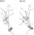
- FIG. 9 for the embodiment of FIG. 2 shows the same position of the components as in FIG. 5 once the safety bracket 8 has been opened as has been described in the context of FIGS. 3 to 5 .
- the safety bracket 8 is in the opened position, and the bolt 3 of the locking element 10 is at the topmost position of the slot 11 .
- a lengthened slot 11 is now used instead of the short slot 9 (as is illustrated in FIG. 5 ).
- FIG. 10 the control element 6 that by the transmission installation 2 has been moved right to the top is again in the same position as shown in FIG. 2 , the substantial difference being that the safety bracket 8 has not been conjointly moved and closed by virtue of the long slot 11 .
- the safety bracket 8 in the illustrated position of the control element 6 can be manually closed by a passenger, as is shown in FIGS. 11 and 12 .
- the safety bracket 8 in FIG. 11 has already been partially manually closed by a passenger.
- the blocking element 7 now bears on the protrusion 16 of the depression 14 of the locking element 10 .
- a plurality of depressions or recesses can be provided sequentially on the locking element 10 in the direction of movements such that the blocking element 7 during the closing procedure successively engages in one recess or depression after the other, thus progressively blocking the safety bracket 8 successively and in a step-by-step manner from being opened again by a passenger.
- the locking element 10 in FIG. 12 is locked by the blocking element 7 , as is also illustrated in FIG. 2 .
- the blocking element 7 is again in the depression 14 of the locking element 10 , and blocks the safety bracket 8 in the closed position.
- the safety bracket 8 can only be unlocked and opened again by external activation by way of the transmission installation 2 .
- the locking device 1 according to the invention can also be used, according to the same principle as has been described in FIGS. 1 to 12 for weather protection hoods, for example.
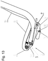
- FIG. 13 The use for an externally activated pivoting of a seat part 17 of a seat of a chairlift is illustrated in FIG. 13 .
- the functions and embodiments of the slots 9 or 11 , respectively, in the short or long embodiment in the control element 6 correspond to those that have already been described in FIGS. 3 to 12 .
- the locking device 1 can also be disposed between the seat part 17 and the frame of the seat, said seat part 17 in this illustration being in the sitting position.
- the locking element 10 is connected to the seat part 17 in order for the seat parts to be pivoted to the opened and the closed position.
- the same device can also serve for pivoting a back part 18 .
- a further improved embodiment of the locking device 1 on the seat part 17 serves for enhancing the comfort and the safety when boarding and alighting, in particular for comparatively small passengers and those with mobility difficulties.
- a front edge 19 of the seat part 17 In order for boarding and alighting to be facilitated, it is advantageous for a front edge 19 of the seat part 17 to be inclined downward as far as possible.
- a force by way of which the seat part 17 by way of the locking element 10 is pushed further down against an elastic element 20 can be applied to the control element 6 by way of the transmission installation 2 . Once the passengers are seated, the tilting element 5 of the locking device 1 is de-stressed.
- the front edge 19 is moved upward again on account of the force that is stored in the elastic element 20 , the seat part 17 is slightly reclined, and the blocking element 7 latches back into the depression 14 of the locking element 10 .
- the spacing between the seat part 17 and the safety bracket 8 is thus also decreased, and the risk of comparatively small passengers slipping through below the safety bracket 8 is reduced.
- this is not disadvantageous but rather offers the additional advantage that there is automatically more space below the safety bracket 8 for these people who are in most cases also comparatively large, thus enhancing the comfort for these people.
- the depression 14 on the locking element can also be disposed such that the blocking element 7 latches when the seat part is in the lowermost position, on account of which the seat part remains in the lowermost boarding and alighting position during the entire passage of the chair through a station.
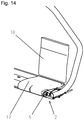
- FIG. 14 shows the embodiment of the locking device 1 described in FIG. 13 in an oblique view.
Landscapes
- Engineering & Computer Science (AREA)
- Transportation (AREA)
- Mechanical Engineering (AREA)
- Chairs For Special Purposes, Such As Reclining Chairs (AREA)
- Chairs Characterized By Structure (AREA)
- Seats For Vehicles (AREA)
- Lock And Its Accessories (AREA)
Abstract
Description
Claims (20)
Applications Claiming Priority (3)
| Application Number | Priority Date | Filing Date | Title |
|---|---|---|---|
| ATA452/2015A AT517204B1 (en) | 2015-07-09 | 2015-07-09 | Armchair for a chairlift |
| ATA452/2015 | 2015-07-09 | ||
| PCT/EP2016/066432 WO2017005934A1 (en) | 2015-07-09 | 2016-07-11 | Chair for a chairlift |
Publications (2)
| Publication Number | Publication Date |
|---|---|
| US20180194370A1 US20180194370A1 (en) | 2018-07-12 |
| US11001275B2 true US11001275B2 (en) | 2021-05-11 |
Family
ID=56372932
Family Applications (1)
| Application Number | Title | Priority Date | Filing Date |
|---|---|---|---|
| US15/742,598 Active 2037-07-07 US11001275B2 (en) | 2015-07-09 | 2016-07-11 | Chair for a chairlift |
Country Status (11)
| Country | Link |
|---|---|
| US (1) | US11001275B2 (en) |
| EP (1) | EP3319856B1 (en) |
| JP (1) | JP6559321B2 (en) |
| KR (1) | KR102019809B1 (en) |
| CN (1) | CN107835769B (en) |
| AT (2) | AT517204B1 (en) |
| AU (1) | AU2016289521B2 (en) |
| CA (1) | CA2991371C (en) |
| ES (1) | ES2848379T3 (en) |
| NZ (1) | NZ738543A (en) |
| WO (2) | WO2017004629A1 (en) |
Families Citing this family (1)
| Publication number | Priority date | Publication date | Assignee | Title |
|---|---|---|---|---|
| AT516705B1 (en) * | 2015-04-02 | 2016-08-15 | Innova Patent Gmbh | Device for locking a pivotable protective device for a chairlift |
Citations (16)
| Publication number | Priority date | Publication date | Assignee | Title |
|---|---|---|---|---|
| EP0510357B1 (en) | 1991-04-22 | 1994-09-14 | KONRAD DOPPELMAYR & SOHN MASCHINENFABRIK GESELLSCHAFT M.B.H. & CO. KG. | Automatic locking device for a weather protection cap of a chairlift or the door of a telpher carrier |
| EP0748732A1 (en) | 1995-06-14 | 1996-12-18 | LEITNER S.p.A. | Actuating and supporting device of protective elements esp. of protective caps and doors of cableway installations |
| EP0808757A1 (en) * | 1996-05-21 | 1997-11-26 | LEITNER S.p.A. | Fall-guard for the chairs of chairlifts |
| US6106067A (en) * | 1996-07-25 | 2000-08-22 | P.L. Porter Co., | Seat adjustment and dumping mechanism with memory adjustment coordinated with seat positioning |
| EP1671867A1 (en) | 2004-12-17 | 2006-06-21 | Pomagalski S.A. | Control system for the locking of a pivotable hood for a chair lift |
| EP1780091A2 (en) | 2005-10-28 | 2007-05-02 | Innova Patent GmbH | Cableway for transporting passengers with a safety device |
| WO2008020021A1 (en) | 2006-08-16 | 2008-02-21 | High Technology Investments B.V. | Chair-lift chair safety device with a crossbar lock-release control device |
| EP2030858A2 (en) | 2007-08-30 | 2009-03-04 | Innova Patent GmbH | Seat of a chair-lift or a ropeway |
| DE102010017068A1 (en) | 2010-05-22 | 2011-11-24 | Werner Stoffaneller | Chair lift lever locking arrangement |
| US8590458B2 (en) * | 2007-04-20 | 2013-11-26 | Rolic Invest S.Ar.L. | Chair-lift |
| WO2013190220A1 (en) | 2012-06-20 | 2013-12-27 | Sommital | Mechanical chairlift seat and installation equipped with this seat |
| EP2810841A1 (en) * | 2013-06-06 | 2014-12-10 | Bartholet Maschinenbau AG | Drive operation device for a circular path and method for operating a circular path with such a drive operation device |
| US20150000548A1 (en) | 2011-11-16 | 2015-01-01 | Sommital | Mechanical lift vehicle |
| US20180087300A1 (en) * | 2015-04-02 | 2018-03-29 | Innova Patent Gmbh | Device for locking a pivotal protective device for a chairlift |
| US20180251137A1 (en) * | 2015-07-09 | 2018-09-06 | Innova Patent Gmbh | Chair For A Chairlift |
| US20190300022A1 (en) * | 2016-05-24 | 2019-10-03 | Poma | Transport vehicle designed to be pulled by an overhead cable and installation comprising a vehicle of said type |
Family Cites Families (4)
| Publication number | Priority date | Publication date | Assignee | Title |
|---|---|---|---|---|
| DE29517263U1 (en) * | 1995-10-31 | 1997-02-27 | Garaventa Holding Ag, Goldau | Actuating and locking mechanism for weather protection hoods of chair lifts |
| AT510521B1 (en) * | 2010-10-14 | 2012-12-15 | Innova Patent Gmbh | FOOTREST |
| FR2969100B1 (en) * | 2010-12-17 | 2013-01-11 | Sommital | MECHANICAL REVERSE SEAT WITH MAGNETIC LOCKING OF BODYWORK |
| FR3006654B1 (en) * | 2013-06-05 | 2015-07-17 | Pomagalski Sa | PASSENGER PROTECTION DEVICE FOR MOUNTING ON A SEAT OF A TELESIEGE |
-
2015
- 2015-07-09 AT ATA452/2015A patent/AT517204B1/en not_active IP Right Cessation
- 2015-07-23 AT ATA492/2015A patent/AT516943B1/en not_active IP Right Cessation
-
2016
- 2016-05-30 WO PCT/AT2016/000059 patent/WO2017004629A1/en not_active Ceased
- 2016-07-11 NZ NZ738543A patent/NZ738543A/en not_active IP Right Cessation
- 2016-07-11 JP JP2018500635A patent/JP6559321B2/en not_active Expired - Fee Related
- 2016-07-11 US US15/742,598 patent/US11001275B2/en active Active
- 2016-07-11 EP EP16736508.9A patent/EP3319856B1/en active Active
- 2016-07-11 CA CA2991371A patent/CA2991371C/en active Active
- 2016-07-11 AU AU2016289521A patent/AU2016289521B2/en not_active Ceased
- 2016-07-11 KR KR1020187003683A patent/KR102019809B1/en not_active Expired - Fee Related
- 2016-07-11 CN CN201680040420.XA patent/CN107835769B/en active Active
- 2016-07-11 WO PCT/EP2016/066432 patent/WO2017005934A1/en not_active Ceased
- 2016-07-11 ES ES16736508T patent/ES2848379T3/en active Active
Patent Citations (22)
| Publication number | Priority date | Publication date | Assignee | Title |
|---|---|---|---|---|
| JPH0769209A (en) | 1991-04-22 | 1995-03-14 | Konrad Doppelmayr & Sohn Mas Fab Gmbh & Co Kg | Suspension device |
| EP0510357B1 (en) | 1991-04-22 | 1994-09-14 | KONRAD DOPPELMAYR & SOHN MASCHINENFABRIK GESELLSCHAFT M.B.H. & CO. KG. | Automatic locking device for a weather protection cap of a chairlift or the door of a telpher carrier |
| EP0748732A1 (en) | 1995-06-14 | 1996-12-18 | LEITNER S.p.A. | Actuating and supporting device of protective elements esp. of protective caps and doors of cableway installations |
| EP0808757A1 (en) * | 1996-05-21 | 1997-11-26 | LEITNER S.p.A. | Fall-guard for the chairs of chairlifts |
| US6106067A (en) * | 1996-07-25 | 2000-08-22 | P.L. Porter Co., | Seat adjustment and dumping mechanism with memory adjustment coordinated with seat positioning |
| EP1671867A1 (en) | 2004-12-17 | 2006-06-21 | Pomagalski S.A. | Control system for the locking of a pivotable hood for a chair lift |
| JP2006168725A (en) | 2004-12-17 | 2006-06-29 | Pomagalski Sa | Operating mechanism with latching of pivoting cover for chair-lift |
| US7377220B2 (en) * | 2004-12-17 | 2008-05-27 | Pomagalski Sa | Operating mechanism with latching of a pivoting cover for a chair-lift |
| EP1780091A2 (en) | 2005-10-28 | 2007-05-02 | Innova Patent GmbH | Cableway for transporting passengers with a safety device |
| US7690313B2 (en) | 2005-10-28 | 2010-04-06 | Innova Patent Gmbh | Cableway system with a safety device |
| WO2008020021A1 (en) | 2006-08-16 | 2008-02-21 | High Technology Investments B.V. | Chair-lift chair safety device with a crossbar lock-release control device |
| US8590458B2 (en) * | 2007-04-20 | 2013-11-26 | Rolic Invest S.Ar.L. | Chair-lift |
| EP2030858A2 (en) | 2007-08-30 | 2009-03-04 | Innova Patent GmbH | Seat of a chair-lift or a ropeway |
| US7984678B2 (en) * | 2007-08-30 | 2011-07-26 | Innova Patent Gmbh | Transporting means of a chair lift or of a cableway system |
| DE102010017068A1 (en) | 2010-05-22 | 2011-11-24 | Werner Stoffaneller | Chair lift lever locking arrangement |
| US20150000548A1 (en) | 2011-11-16 | 2015-01-01 | Sommital | Mechanical lift vehicle |
| WO2013190220A1 (en) | 2012-06-20 | 2013-12-27 | Sommital | Mechanical chairlift seat and installation equipped with this seat |
| US9701320B2 (en) * | 2012-06-20 | 2017-07-11 | Sommital | Mechanical lift seat and installation equipped with this seat |
| EP2810841A1 (en) * | 2013-06-06 | 2014-12-10 | Bartholet Maschinenbau AG | Drive operation device for a circular path and method for operating a circular path with such a drive operation device |
| US20180087300A1 (en) * | 2015-04-02 | 2018-03-29 | Innova Patent Gmbh | Device for locking a pivotal protective device for a chairlift |
| US20180251137A1 (en) * | 2015-07-09 | 2018-09-06 | Innova Patent Gmbh | Chair For A Chairlift |
| US20190300022A1 (en) * | 2016-05-24 | 2019-10-03 | Poma | Transport vehicle designed to be pulled by an overhead cable and installation comprising a vehicle of said type |
Non-Patent Citations (1)
| Title |
|---|
| Machine translation of EP-0808757-A1 (Year: 1997). * |
Also Published As
| Publication number | Publication date |
|---|---|
| AU2016289521A1 (en) | 2018-02-01 |
| CN107835769B (en) | 2020-06-16 |
| JP2018520047A (en) | 2018-07-26 |
| AT517204A4 (en) | 2016-12-15 |
| WO2017005934A1 (en) | 2017-01-12 |
| WO2017004629A1 (en) | 2017-01-12 |
| CA2991371A1 (en) | 2017-01-12 |
| KR20180030578A (en) | 2018-03-23 |
| AU2016289521B2 (en) | 2019-05-23 |
| EP3319856B1 (en) | 2020-12-02 |
| EP3319856A1 (en) | 2018-05-16 |
| US20180194370A1 (en) | 2018-07-12 |
| NZ738543A (en) | 2019-05-31 |
| JP6559321B2 (en) | 2019-08-14 |
| AT517204B1 (en) | 2016-12-15 |
| CN107835769A (en) | 2018-03-23 |
| KR102019809B1 (en) | 2019-09-09 |
| CA2991371C (en) | 2019-09-24 |
| ES2848379T3 (en) | 2021-08-09 |
| AT516943B1 (en) | 2016-10-15 |
| AT516943A4 (en) | 2016-10-15 |
Similar Documents
| Publication | Publication Date | Title |
|---|---|---|
| US10696407B2 (en) | Tray table arms with rotation stopper override | |
| CN101711207B (en) | aerial chair | |
| US7690313B2 (en) | Cableway system with a safety device | |
| CN102803013A (en) | Vehicle seat | |
| CN113242829B (en) | Closing device for a passage between two seat units | |
| US8443734B2 (en) | Pivoting system for a chair | |
| CN110167791B (en) | Adjustable seat with entry roll and pitch slide | |
| US11001275B2 (en) | Chair for a chairlift | |
| CA2991370C (en) | Chair for a chairlift | |
| US9580082B2 (en) | Mechanical lift vehicle | |
| CN100532153C (en) | Motor vehicle seat | |
| WO2021116190A1 (en) | Vehicle seat | |
| JP7435973B2 (en) | Safety bar lock device for chairlift carrier | |
| US970010A (en) | Passenger-car. |
Legal Events
| Date | Code | Title | Description |
|---|---|---|---|
| FEPP | Fee payment procedure |
Free format text: ENTITY STATUS SET TO UNDISCOUNTED (ORIGINAL EVENT CODE: BIG.); ENTITY STATUS OF PATENT OWNER: LARGE ENTITY |
|
| AS | Assignment |
Owner name: INNOVA PATENT GMBH, AUSTRIA Free format text: ASSIGNMENT OF ASSIGNORS INTEREST;ASSIGNORS:SUTTERLUETY, ANDREAS;PASSLER, RENE;SIGNING DATES FROM 20171123 TO 20171201;REEL/FRAME:044597/0726 |
|
| STPP | Information on status: patent application and granting procedure in general |
Free format text: DOCKETED NEW CASE - READY FOR EXAMINATION |
|
| STPP | Information on status: patent application and granting procedure in general |
Free format text: RESPONSE TO NON-FINAL OFFICE ACTION ENTERED AND FORWARDED TO EXAMINER |
|
| STPP | Information on status: patent application and granting procedure in general |
Free format text: NON FINAL ACTION MAILED |
|
| STPP | Information on status: patent application and granting procedure in general |
Free format text: RESPONSE TO NON-FINAL OFFICE ACTION ENTERED AND FORWARDED TO EXAMINER |
|
| STPP | Information on status: patent application and granting procedure in general |
Free format text: NOTICE OF ALLOWANCE MAILED -- APPLICATION RECEIVED IN OFFICE OF PUBLICATIONS |
|
| STPP | Information on status: patent application and granting procedure in general |
Free format text: PUBLICATIONS -- ISSUE FEE PAYMENT RECEIVED |
|
| STPP | Information on status: patent application and granting procedure in general |
Free format text: PUBLICATIONS -- ISSUE FEE PAYMENT VERIFIED |
|
| STCF | Information on status: patent grant |
Free format text: PATENTED CASE |
|
| MAFP | Maintenance fee payment |
Free format text: PAYMENT OF MAINTENANCE FEE, 4TH YEAR, LARGE ENTITY (ORIGINAL EVENT CODE: M1551); ENTITY STATUS OF PATENT OWNER: LARGE ENTITY Year of fee payment: 4 |