US10959692B2 - X-ray imaging apparatus - Google Patents
X-ray imaging apparatus Download PDFInfo
- Publication number
- US10959692B2 US10959692B2 US16/060,596 US201516060596A US10959692B2 US 10959692 B2 US10959692 B2 US 10959692B2 US 201516060596 A US201516060596 A US 201516060596A US 10959692 B2 US10959692 B2 US 10959692B2
- Authority
- US
- United States
- Prior art keywords
- ray
- unit
- ray irradiation
- relative position
- ray detection
- Prior art date
- Legal status (The legal status is an assumption and is not a legal conclusion. Google has not performed a legal analysis and makes no representation as to the accuracy of the status listed.)
- Active, expires
Links
- 238000003384 imaging method Methods 0.000 title claims abstract description 208
- 238000001514 detection method Methods 0.000 claims abstract description 158
- 238000000034 method Methods 0.000 claims description 6
- 238000012545 processing Methods 0.000 description 27
- 230000008859 change Effects 0.000 description 7
- 230000006870 function Effects 0.000 description 5
- 230000003287 optical effect Effects 0.000 description 5
- 210000003141 lower extremity Anatomy 0.000 description 4
- 238000012986 modification Methods 0.000 description 4
- 230000004048 modification Effects 0.000 description 4
- 210000004204 blood vessel Anatomy 0.000 description 3
- 239000002872 contrast media Substances 0.000 description 3
- 238000005516 engineering process Methods 0.000 description 3
- 230000005055 memory storage Effects 0.000 description 3
- 230000005855 radiation Effects 0.000 description 3
- 238000003066 decision tree Methods 0.000 description 2
- 238000010586 diagram Methods 0.000 description 2
- 239000000835 fiber Substances 0.000 description 2
- 238000007689 inspection Methods 0.000 description 2
- 238000002583 angiography Methods 0.000 description 1
- 238000004891 communication Methods 0.000 description 1
- 230000008867 communication pathway Effects 0.000 description 1
- 238000004590 computer program Methods 0.000 description 1
- 230000001419 dependent effect Effects 0.000 description 1
- 238000013461 design Methods 0.000 description 1
- 230000001066 destructive effect Effects 0.000 description 1
- 230000000694 effects Effects 0.000 description 1
- 238000002438 flame photometric detection Methods 0.000 description 1
- 238000002594 fluoroscopy Methods 0.000 description 1
- 230000002093 peripheral effect Effects 0.000 description 1
- 239000007787 solid Substances 0.000 description 1
- 238000012360 testing method Methods 0.000 description 1
- 238000012546 transfer Methods 0.000 description 1
Images


Classifications
-
- A—HUMAN NECESSITIES
- A61—MEDICAL OR VETERINARY SCIENCE; HYGIENE
- A61B—DIAGNOSIS; SURGERY; IDENTIFICATION
- A61B6/00—Apparatus or devices for radiation diagnosis; Apparatus or devices for radiation diagnosis combined with radiation therapy equipment
- A61B6/44—Constructional features of apparatus for radiation diagnosis
- A61B6/4429—Constructional features of apparatus for radiation diagnosis related to the mounting of source units and detector units
- A61B6/4452—Constructional features of apparatus for radiation diagnosis related to the mounting of source units and detector units the source unit and the detector unit being able to move relative to each other
-
- A—HUMAN NECESSITIES
- A61—MEDICAL OR VETERINARY SCIENCE; HYGIENE
- A61B—DIAGNOSIS; SURGERY; IDENTIFICATION
- A61B6/00—Apparatus or devices for radiation diagnosis; Apparatus or devices for radiation diagnosis combined with radiation therapy equipment
-
- A—HUMAN NECESSITIES
- A61—MEDICAL OR VETERINARY SCIENCE; HYGIENE
- A61B—DIAGNOSIS; SURGERY; IDENTIFICATION
- A61B6/00—Apparatus or devices for radiation diagnosis; Apparatus or devices for radiation diagnosis combined with radiation therapy equipment
- A61B6/02—Arrangements for diagnosis sequentially in different planes; Stereoscopic radiation diagnosis
- A61B6/03—Computed tomography [CT]
-
- A—HUMAN NECESSITIES
- A61—MEDICAL OR VETERINARY SCIENCE; HYGIENE
- A61B—DIAGNOSIS; SURGERY; IDENTIFICATION
- A61B6/00—Apparatus or devices for radiation diagnosis; Apparatus or devices for radiation diagnosis combined with radiation therapy equipment
- A61B6/04—Positioning of patients; Tiltable beds or the like
-
- A—HUMAN NECESSITIES
- A61—MEDICAL OR VETERINARY SCIENCE; HYGIENE
- A61B—DIAGNOSIS; SURGERY; IDENTIFICATION
- A61B6/00—Apparatus or devices for radiation diagnosis; Apparatus or devices for radiation diagnosis combined with radiation therapy equipment
- A61B6/42—Arrangements for detecting radiation specially adapted for radiation diagnosis
- A61B6/4208—Arrangements for detecting radiation specially adapted for radiation diagnosis characterised by using a particular type of detector
-
- A—HUMAN NECESSITIES
- A61—MEDICAL OR VETERINARY SCIENCE; HYGIENE
- A61B—DIAGNOSIS; SURGERY; IDENTIFICATION
- A61B6/00—Apparatus or devices for radiation diagnosis; Apparatus or devices for radiation diagnosis combined with radiation therapy equipment
- A61B6/44—Constructional features of apparatus for radiation diagnosis
- A61B6/4429—Constructional features of apparatus for radiation diagnosis related to the mounting of source units and detector units
- A61B6/4435—Constructional features of apparatus for radiation diagnosis related to the mounting of source units and detector units the source unit and the detector unit being coupled by a rigid structure
- A61B6/4441—Constructional features of apparatus for radiation diagnosis related to the mounting of source units and detector units the source unit and the detector unit being coupled by a rigid structure the rigid structure being a C-arm or U-arm
-
- A—HUMAN NECESSITIES
- A61—MEDICAL OR VETERINARY SCIENCE; HYGIENE
- A61B—DIAGNOSIS; SURGERY; IDENTIFICATION
- A61B6/00—Apparatus or devices for radiation diagnosis; Apparatus or devices for radiation diagnosis combined with radiation therapy equipment
- A61B6/50—Apparatus or devices for radiation diagnosis; Apparatus or devices for radiation diagnosis combined with radiation therapy equipment specially adapted for specific body parts; specially adapted for specific clinical applications
- A61B6/504—Apparatus or devices for radiation diagnosis; Apparatus or devices for radiation diagnosis combined with radiation therapy equipment specially adapted for specific body parts; specially adapted for specific clinical applications for diagnosis of blood vessels, e.g. by angiography
-
- A—HUMAN NECESSITIES
- A61—MEDICAL OR VETERINARY SCIENCE; HYGIENE
- A61B—DIAGNOSIS; SURGERY; IDENTIFICATION
- A61B6/00—Apparatus or devices for radiation diagnosis; Apparatus or devices for radiation diagnosis combined with radiation therapy equipment
- A61B6/54—Control of apparatus or devices for radiation diagnosis
- A61B6/542—Control of apparatus or devices for radiation diagnosis involving control of exposure
-
- A—HUMAN NECESSITIES
- A61—MEDICAL OR VETERINARY SCIENCE; HYGIENE
- A61B—DIAGNOSIS; SURGERY; IDENTIFICATION
- A61B6/00—Apparatus or devices for radiation diagnosis; Apparatus or devices for radiation diagnosis combined with radiation therapy equipment
- A61B6/54—Control of apparatus or devices for radiation diagnosis
- A61B6/545—Control of apparatus or devices for radiation diagnosis involving automatic set-up of acquisition parameters
-
- A—HUMAN NECESSITIES
- A61—MEDICAL OR VETERINARY SCIENCE; HYGIENE
- A61B—DIAGNOSIS; SURGERY; IDENTIFICATION
- A61B6/00—Apparatus or devices for radiation diagnosis; Apparatus or devices for radiation diagnosis combined with radiation therapy equipment
- A61B6/46—Arrangements for interfacing with the operator or the patient
- A61B6/461—Displaying means of special interest
- A61B6/464—Displaying means of special interest involving a plurality of displays
-
- A—HUMAN NECESSITIES
- A61—MEDICAL OR VETERINARY SCIENCE; HYGIENE
- A61B—DIAGNOSIS; SURGERY; IDENTIFICATION
- A61B6/00—Apparatus or devices for radiation diagnosis; Apparatus or devices for radiation diagnosis combined with radiation therapy equipment
- A61B6/48—Diagnostic techniques
- A61B6/481—Diagnostic techniques involving the use of contrast agents
Definitions
- FIG. 1 A first figure.
- the present invention relates to an X-ray imaging apparatus, and more particularly, relates to an X-ray imaging apparatus that performs X-ray imaging while moving a table relative to an X-ray irradiation unit and an X-ray detection unit.
- an X-ray imaging apparatus that performs X-ray imaging while moving a table relative to an X-ray irradiation unit and an X-ray detection unit is known.
- Such an X-ray imaging apparatus is disclosed in Japanese Patent Laid-Open No. 2010-162278, for example.
- An X-ray imaging apparatus disclosed in the aforementioned Japanese Patent Laid-Open No. 2010-162278 includes an X-ray tube that irradiates a subject with X-rays, an X-ray detector that detects the X-rays transmitted through the subject, a C-arm that holds the X-ray tube and the X-ray detector, which face each other, and can move the X-ray tube and the X-ray detector, and a table on which the subject is placed.
- This X-ray imaging apparatus performs X-ray imaging while moving the table relative to the X-ray tube and the X-ray detector. In addition, this X-ray imaging apparatus changes an X-ray imaging direction by rotating the C-arm.
- Patent Document 1 Japanese Patent Laid-Open No. 2010-162278
- the present invention has been proposed in order to solve the aforementioned problem, and an object of the present invention is to provide an X-ray imaging apparatus that can image a specific part from a specific angular direction while preventing an increase in the operation burden on an operator.
- an X-ray imaging apparatus comprises an X-ray irradiation unit that irradiates a subject with X-rays, an X-ray detection unit that detects the X-rays transmitted through the subject, a holding unit that holds the X-ray irradiation unit and the X-ray detection unit, which face each other, and can move the X-ray irradiation unit and the X-ray detection unit, a table on which the subject is placed, and a control unit that controls the move of the holding unit so as to control an X-ray irradiation direction of the X-ray irradiation unit and an X-ray detection direction of the X-ray detection unit are respectively interlocked with a relative position of the table to the X-ray irradiation unit and the X-ray detection unit or the move of the holding unit so as to control the X-ray irradiation direction of the X-ray X-ray
- the control unit of the X-ray imaging apparatus controls the move of the holding unit to control the X-ray irradiation direction of the X-ray irradiation unit and the X-ray detection direction of the X-ray detection unit that are respectively interlocked with the relative position of the table to the X-ray irradiation unit and the X-ray detection unit or based on the operation during the X-ray imaging.
- the relative move of the table and the move of the X-ray imaging direction can be interlocked, so that the operator only needs to operate the move of the table. Consequently, an increase in the operation burden on the operator can be prevented.
- the operator only needs to manipulate the timing to change the X-ray imaging direction, so that the operator need not actually perform a separate operation for moving the X-ray irradiation unit and the X-ray detection unit. Consequently, an increase in the operation burden on the operator is prevented.
- the timing between the relative move of the table and the move of the X-ray imaging direction can be easily adjusted, so that a specific part can be easily imaged from a specific angular direction. Consequently, the imaging of the specific part can be achieved from the specific angular direction while an increase in the operation burden on the operator is being prevented.
- the control unit preferably controls rotating the holding unit around a predetermined rotation axis interlocked with the relative position of the table to the X-ray irradiation unit and the X-ray detection unit, or controls rotating the holding unit around the predetermined rotation axis based on the operation during the X-ray imaging.
- the X-ray imaging direction can be easily changed in accordance with the relative move of the table, so that an increase in the operation burden can be prevented.
- control unit preferably controls the move of the holding unit so as to reciprocate-rotate the X-ray irradiation unit and the X-ray detection unit interlocked with the relative position of the table to the X-ray irradiation unit and the X-ray detection unit, or controls the move of the holding unit so as to reciprocate-rotate the X-ray irradiation unit and the X-ray detection unit based on the operation during the X-ray imaging.
- the X-ray imaging direction can be swung at the desired relative position of the table, so that the imaging of the specific part from the specific angular direction can be more easily performed.
- the control unit preferably controls the move of the holding unit such that the X-ray irradiation direction of the X-ray irradiation unit and the X-ray detection direction of the X-ray detection unit are the same as a preset direction interlocked with the relative position of the table to the X-ray irradiation unit and the X-ray detection unit, or to control the move of the holding unit such that the X-ray irradiation direction of the X-ray irradiation unit and the X-ray detection direction of the X-ray detection unit are the same as the preset direction based on the operation during the X-ray imaging.
- the X-ray imaging direction is the same as a desired direction at the desired relative position of the table with high accuracy.
- control unit preferably controls the X-ray irradiation direction of the X-ray irradiation unit and the X-ray detection direction of the X-ray detection unit by changing a rotation angle of the holding unit. According to this configuration, the X-ray imaging direction can be easily changed by changing the rotation angle of the holding unit.
- the X-ray irradiation direction of the X-ray irradiation unit and the X-ray detection direction of the X-ray detection unit are interlockingly controlled and the relative position of the table to the X-ray irradiation unit and the X-ray detection unit is pre-settable.
- the X-ray imaging direction can be the desired direction at the desired relative position of the table with a higher accuracy.
- control unit preferably controls the movement of the holding unit so as to control the X-ray irradiation direction of the X-ray irradiation unit and the X-ray detection direction of the X-ray detection unit based on a fact that the relative position of the table to the X-ray irradiation unit and the X-ray detection unit has reached a predetermined position.
- the specific part can be easily imaged from the specific angular direction by changing the X-ray imaging direction according to the relative position of the table.
- the X-ray irradiation direction of the X-ray irradiation unit and the X-ray detection direction of the X-ray detection unit are presettable in association with the relative position of the table to the X-ray irradiation unit and the X-ray detection unit and the control unit controls the movement of the holding unit such that the X-ray irradiation direction of the X-ray irradiation unit and the X-ray detection direction of the X-ray detection unit coincide with a preset direction when the relative position of the table with respect to the X-ray irradiation unit and the X-ray detection unit reaches a predetermined intermediate position set in advance.
- the X-ray imaging direction can be easily changed to the set-up direction interlocked with the relative position of the table, so that the specific part can be more easily imaged from the specific angular direction.
- the X-ray irradiation direction of the X-ray irradiation unit and the X-ray detection direction of the X-ray detection unit are presettable in association with each of a first relative position and a second relative position of the table to the X-ray irradiation unit and the X-ray detection unit and the control unit controls such that the X-ray irradiation direction of the X-ray irradiation unit and the X-ray detection direction of the X-ray detection unit coincide with a preset first direction when the relative position of the table to the X-ray irradiation unit and the X-ray detection unit reaches the first relative position set in advance, and to perform control such that the X-ray irradiation direction of the X-ray irradiation unit and the X-ray detection direction of the X-ray detection unit coincide with a preset second direction when the relative position of the table to the X-ray irradiation unit and
- FIG. 1 is a schematic view showing the overall configuration of an X-ray imaging apparatus according to an embodiment of the present invention.
- FIG. 2 is a side view showing the X-ray imaging apparatus according to the embodiment of the present invention.
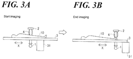
- FIGS. 3A, 3B are diagrams illustrating an operation of a relative movement of a table of the X-ray imaging apparatus according to the embodiment of the present invention.
- FIGS. 4A, 4B, 4C are diagrams illustrating an operation of a movement of the X-ray imaging apparatus and a change of an imaging direction according to the embodiment of the present invention.
- FIG. 5 is a flowchart (decision tree) illustrating X-ray imaging procedure (protocol) of a first operation example performed by the X-ray imaging apparatus according to the embodiment of the present invention.
- FIG. 6 is a flowchart illustrating X-ray imaging procedure (protocol) of a second operation example performed by the X-ray imaging apparatus according to the embodiment of the present invention.
- FIG. 7 is a flowchart illustrating X-ray imaging procedure (protocol) of a third operation example performed by the X-ray imaging apparatus according to the embodiment of the present invention.
- the X-ray imaging apparatus 100 performs an X-ray imaging while additionally relatively moving a subject 10 placed on a table 3 .
- the X-ray imaging apparatus 100 includes an angiography apparatus that radiographs a blood vessel using a contrast medium, for example.
- the X-ray imaging apparatus 100 comprises an X-ray tube 1 , an FPD (flat panel detector) 2 , the table 3 , a holding unit 4 , a control unit 5 , an image processing unit 6 , a display unit 7 , an operation unit 8 , and a memory storage unit 9 .
- the X-ray tube 1 is connected to a driver 11 .
- the table 3 moves in a horizontal direction (directions X and Y) by a table drive unit 31 .
- the table drive unit 31 is connected to a driver 32 .
- the holding unit 4 movably supports the X-ray tube 1 and the FPD 2 .
- the holding unit 4 is driven by a drive unit 41 and rotates.
- the drive unit 41 is connected to a driver 42 .
- the X-ray tube 1 is an example of the X-ray irradiation unit in the claims
- the FPD 2 is the example of an X-ray detection unit in the claims.
- the X-ray imaging apparatus 100 radiographs the subject 10 (human body) lying on the table 3 . Specifically, the X-ray imaging apparatus 100 detects, with the FPD 2 , X-rays radiated from the X-ray tube 1 disposed below the table 3 and transmitted through the subject 10 , and takes an X-ray image. Furthermore, the X-ray imaging apparatus 100 takes an X-ray image while moving the subject 10 (table 3 ) relative to the X-ray tube 1 and the FPD 2 .
- the X-ray imaging apparatus 100 is mainly used to image the lower limb blood vessel of the subject 10 .
- the contrast medium is injected into the blood vessel of the subject 10 in a state where the subject 10 is placed on the table 3 .
- X-ray imaging is performed while the table 3 is moving in the direction X so as to follow the flow of the contrast medium, as shown in FIG. 3A , FIG. 3B .
- the range of X-ray imaging (the X-ray irradiation range of the X-ray tube 1 and the detection range of the FPD 2 ) does not include the entire lower limb of the subject 10 , so that X-ray imaging is performed while the subject 10 (table 3 ) is moving relative to the X-ray tube 1 and the FPD 2 .
- X-ray imaging is started from the base of the lower limb of the subject 10 , and the X-ray imaging is terminated when the tip (toe) of the lower limb of the subject 10 is reached.
- the X-ray tube 1 faces the FPD 2 sandwiching the table 3 .
- the X-ray tube 1 irradiates the subject 10 lying on the table 3 with X-rays.
- the X-ray tube 1 is driven by the driver 11 to generate X-rays.
- the driver 11 is connected to the control unit 5 . Furthermore, the X-ray tube 1 can adjust the intensity and irradiation range of X-rays to be generated.
- the FPD 2 detects the X-rays radiated from the X-ray tube 1 and transmitted through the subject 10 .
- the FPD 2 images an X-ray image based on the detected X-rays. Specifically, the FPD 2 converts the detected X-rays to an electrical signal. Information about the X-rays converted to the electric signal is transmitted to the image processing unit 6 .
- the X-ray tube 1 and the FPD 2 start imaging an X-ray image based on an instruction to start imaging input via the operation unit 8 from a user (practitioner). That is, based on the user's instruction to start imaging, the X-ray tube 1 radiates X-rays, and the FPD 2 detects the X-rays. In addition, the X-ray tube 1 and the FPD 2 terminates or suspends imaging an X-ray image based on an instruction to terminate imaging or suspend imaging, input via the operation unit 8 from the user. That is, based on the user's instruction to terminate imaging or suspend imaging, the X-ray tube 1 stops radiating the X-rays, and the FPD 2 stops detecting the X-rays.
- the table 3 is movable relative to the X-ray tube 1 and the FPD 2 in a state where the subject 10 lies (is placed) thereon. Specifically, the table 3 is movable in the body axis direction (direction X) of the lying subject 10 and a direction (direction Y) perpendicular to the body axis direction of the subject 10 .
- the table 3 moves in the horizontal direction by the table drive unit 31 disposed at the lower side. In other words, the table 3 moves by the table drive unit 31 based on the operation of the user or a set-up route.
- the table drive unit 31 is connected to the control unit 5 via the driver 32 .
- the control unit 5 controls the table drive unit 31 to drive the table 3 .
- the route and speed are controlled with a pre-registered program.
- the table 3 can be driven based on the operation of the user. Furthermore, the table 3 can be moved in the horizontal direction manually by the user.
- the holding unit 4 holds the X-ray tube 1 and the FPD 2 such that the X-ray tube 1 and the FPD 2 face each other.
- the holding unit 4 has a C-shape curved to bypass the table 3 .
- the X-ray tube 1 is disposed in the vicinity of a lower end of the holding unit 4
- the FPD 2 is disposed in the vicinity of an upper end of the holding unit 4 .
- the holding unit 4 moves the X-ray tube 1 and the FPD 2 .
- the holding unit 4 moves such that the X-ray tube 1 and the FPD 2 face each other at a predetermined angle with respect to a vertical direction (direction Z) referencing a position where the X-ray tube 1 and the FPD 2 face each other in the vertical direction.
- the holding unit 4 rotates around a predetermined rotation axis.
- the holding unit 4 rotates around the body axis direction (direction X) of the subject 10 , for example, the holding unit 4 performs a pendulum motion (swinging).
- the holding unit 4 rotates around the vertical direction (direction Z)
- the holding unit 4 performs a precession motion.
- the holding unit 4 is driven by the drive unit 41 .
- the drive unit 41 is attached to a ceiling and supports the holding unit 4 from above. That is, the X-ray imaging apparatus 100 is a ceiling-suspended X-ray imaging apparatus.
- the drive unit 41 is connected to the control unit 5 via the driver 42 .
- the control unit 5 controls the drive unit 41 to drive the holding unit 4 .
- the control unit 5 controls each unit of the X-ray imaging apparatus 100 . Specifically, the control unit 5 controls the X-ray tube 1 via the driver 11 . Furthermore, the control unit 5 controls driving of the table drive unit 31 via the driver 32 . The control unit 5 also controls driving of the drive unit 41 via the driver 42 . In addition, the control unit 5 controls the display unit 7 to display an X-ray image generated by the image processing unit 6 . The control unit 5 receives an operation via the operation unit 8 . The control unit 5 controls the memory storage unit 9 to store the X-ray image.
- the image processing unit 6 generates an X-ray image based on the X-rays detected by the FPD 2 .
- the display unit 7 displays a captured X-ray image.
- the display unit 7 also displays information about the state of the X-ray imaging apparatus 100 , an image relating to the operation of the X-ray imaging apparatus 100 , etc.
- the operation unit 8 receives an operation input from the user.
- the operation unit 8 comprises a mouse, a keyboard, a touch panel, a foot switch, a hand switch, or the like, for example.
- the X-ray imaging apparatus 100 is operated by operating the operation unit 8 .
- the control unit 5 controls movement of the holding unit 4 so as to control the X-ray irradiation direction of the X-ray tube 1 and the X-ray detection direction of the FPD 2 (X-ray imaging direction) interlocked with the relative position of the table 3 with respect to the X-ray tube 1 and the FPD 2 when the X-ray imaging apparatus 100 performs X-ray imaging while moving the table 3 relative to the X-ray tube 1 and the FPD 2 .
- the relative position of the table 3 to the X-ray tube 1 and the FPD 2 interlocked with which the X-ray irradiation direction of the X-ray tube 1 and the X-ray detection direction of the FPD 2 are controlled is presettable.
- control unit 5 controls the movement of the holding unit 4 so as to control the X-ray irradiation direction of the X-ray tube 1 and the X-ray detection direction of the FPD 2 based on the operation of the user during X-ray imaging.
- control unit 5 controls rotating the holding unit 4 around the predetermined rotation axis interlocked with the relative position of the table 3 to the X-ray tube 1 and the FPD 2 .
- control unit 5 controls rotating the holding unit 4 around the predetermined rotation axis based on the operation during X-ray imaging.
- the control unit 5 controls the movement of the holding unit 4 so as to reciprocate-rotate the X-ray tube 1 and the FPD 2 interlocked with the relative position of the table 3 with respect to the X-ray tube 1 and the FPD 2 .
- control unit 5 controls the movement of the holding unit 4 so as to reciprocate-rotate the X-ray tube 1 and the FPD 2 based on the operation during X-ray imaging.
- control unit 5 controls the movement of the holding unit 4 such that the X-ray irradiation direction of the X-ray tube 1 and the X-ray detection direction of the FPD 2 (X-ray imaging direction) coincide with a preset direction in interlocking with the relative position of the table 3 to the X-ray tube 1 and the FPD 2 .
- control unit 5 controls the movement of the holding unit 4 such that the X-ray irradiation direction of the X-ray tube 1 and the X-ray detection direction of the FPD 2 coincide with the preset direction based on the operation during X-ray imaging.
- the control unit 5 controls the X-ray irradiation direction of the X-ray tube 1 and the X-ray detection direction of the FPD 2 by changing the rotation angle of the holding unit 4 .
- control unit 5 controls the movement of the holding unit 4 so as to control the X-ray irradiation direction of the X-ray tube 1 and the X-ray detection direction of the FPD 2 when the relative position of the table 3 with respect to the X-ray tube 1 and the FPD 2 reaches a predetermined position.
- the X-ray irradiation direction of the X-ray tube 1 and the X-ray detection direction of the FPD 2 are presettable in association with the relative position of the table 3 to the X-ray tube 1 and the FPD 2 .
- the control unit 5 controls movement of the holding unit 4 such that the X-ray irradiation direction of the X-ray tube 1 and the X-ray detection direction of the FPD 2 coincide with the preset direction when the relative position of the table 3 to the X-ray tube 1 and the FPD 2 reaches a predetermined intermediate position set in advance.
- the X-ray irradiation direction of the X-ray tube 1 and the X-ray detection direction of the FPD 2 are presettable in association with each of a first relative position and a second relative position of the table 3 to the X-ray tube 1 and the FPD 2 .
- the control unit 5 is configured to perform control such that the X-ray irradiation direction of the X-ray tube 1 and the X-ray detection direction of the FPD 2 coincide with a preset first direction when the relative position of the table 3 to the X-ray tube 1 and the FPD 2 reaches the first relative position set in advance, and to perform control such that the X-ray irradiation direction of the X-ray tube 1 and the X-ray detection direction of the FPD 2 coincide with a preset second direction when the relative position of the table 3 to the X-ray tube 1 and the FPD 2 reaches the second relative position.
- X-ray imaging processing of a first operation example performed by the X-ray imaging apparatus 100 according to the present embodiment is described with reference to FIG. 5 .
- the first operation example an example in which a change in the X-ray imaging direction is started interlockingly with the relative movement of the table 3 to the X-ray tube 1 and the FPD 2 is described.
- the X-ray imaging apparatus 100 receives an instruction to start imaging via the operation unit 8 from the user in a state where the relative position of the table 3 , at which a pendulum motion of the X-ray tube 1 and the FPD 2 is started, is registered, while the subject (a person to be imaged) 10 is lying (is placed) on the table 3 , the X-ray imaging apparatus 100 starts X-ray imaging in the step S 1 .
- the movement of the table 3 is started. Specifically, X-rays are radiated from the X-ray tube 1 .
- the X-rays are detected by the FPD 2 , and an X-ray image is generated by the image processing unit 6 .
- the table 3 is moved relative to the X-ray tube 1 and the FPD 2 .
- the table 3 can be automatically moved along a registered trajectory or can be manually moved by the user.
- step S 2 it is determined whether or not the table 3 has reached the registered relative position. That is, it is determined whether or not the table 3 has reached the registered relative position as the table 3 is moved relative to the X-ray tube 1 and the FPD 2 during X-ray imaging.
- the determination in the step S 2 is repeated, and when the table 3 has reached the registered relative position, the processing advances to the step S 3 .
- step S 3 the pendulum motion of the X-ray tube 1 and the FPD 2 is started. Specifically, the holding unit 4 is driven, and the X-ray tube 1 and the FPD 2 are rotated around the body axis direction (direction X) of the subject 10 as a rotation axis.
- step S 4 it is determined whether or not the table 3 has reached an imaging end position. When the table 3 has not reached the imaging end position, the determination in the step S 4 is repeated, and when the table 3 has reached the imaging end position, the processing advances to the step S 5 .
- step S 5 X-ray imaging is stopped. At this time, the movement of the table 3 is stopped. Specifically, the radiation of X-rays from the X-ray tube 1 is stopped. When the table 3 moves automatically, the movement of the table 3 is stopped. Thereafter, the X-ray imaging processing is terminated.
- X-ray imaging processing of a second operation example performed by the X-ray imaging apparatus 100 according to the present embodiment is described with reference to FIG. 6 .
- the second operation example an example in which a change in the X-ray imaging direction is started based on the operation of the user during X-ray imaging is described.
- the X-ray imaging apparatus 100 When the subject (a person to be imaged) 10 lies (is placed) on the table 3 , and the X-ray imaging apparatus 100 receives an instruction to start imaging via the operation unit 8 from the user, the X-ray imaging apparatus 100 starts X-ray imaging in the step S 11 . At this time, the movement of the table 3 is started. Specifically, X-rays are radiated from the X-ray tube 1 . The X-rays are detected by the FPD 2 , and an X-ray image is generated by the image processing unit 6 . Furthermore, the table 3 is moved relative to the X-ray tube 1 and the FPD 2 . In addition, the table 3 can be automatically moved along the registered trajectory or can be manually moved by the user.
- step S 12 it is determined whether or not an operation for starting a pendulum motion has been received. Specifically, it is determined whether or not an operation for starting a pendulum motion to change the X-ray imaging direction has been received via the operation unit 8 from the user. When the operation has not been received, the determination in the step S 12 is repeated, and when the operation has been received, the processing advances to the step S 13 .
- step S 13 the pendulum motion of the X-ray tube 1 and the FPD 2 is started. Specifically, the holding unit 4 is driven, and the X-ray tube 1 and the FPD 2 are rotated around the body axis direction (direction X) of the subject 10 as a rotation axis.
- step S 14 it is determined whether or not the table 3 has reached the imaging end position. When the table 3 has not reached the imaging end position, the decision test in the step S 14 is repeated, and when the table 3 has reached the imaging end position, the processing advances to the step S 15 .
- the X-ray imaging is suspended.
- the movement of the table 3 is suspended. Specifically, the radiation of X-rays from the X-ray tube 1 is suspended.
- the table 3 moves automatically, the movement of the table 3 is suspended. Thereafter, the X-ray imaging processing is terminated.
- X-ray imaging processing of a third operation example performed by the X-ray imaging apparatus 100 according to the present embodiment is described with reference to FIG. 7 .
- the third operation example an example in which the X-ray imaging direction is changed to a predetermined direction in association with the relative position of the table 3 to the X-ray tube 1 and the FPD 2 is described.
- the X-ray imaging apparatus 100 When the subject 10 (a person to be imaged) lies (is placed) on the table 3 , and the X-ray imaging apparatus 100 receives an instruction to start imaging via the operation unit 8 from the user in a state where the relative position of the table 3 at which a pendulum motion of the X-ray tube 1 and the FPD 2 is started has been registered, the X-ray imaging apparatus 100 starts the X-ray imaging in the step S 21 . At this time, the movement of the table 3 is started. Specifically, X-rays are radiated from the X-ray tube 1 . The X-rays are detected by the FPD 2 , and an X-ray image is generated by the image processing unit 6 . Furthermore, the table 3 is moved relative to the X-ray tube 1 and the FPD 2 . In addition, the table 3 can be automatically moved along the registered trajectory or can be manually moved by the user.
- step S 22 it is determined whether or not the table 3 has approached the registered first relative position. That is, it is determined whether or not the table 3 has approached the registered first relative position as the table 3 is moved relative to the X-ray tube 1 and the FPD 2 during X-ray imaging.
- the determination in the step S 22 is repeated, and when the table 3 has approached the registered first relative position, the processing advances to the step S 23 .
- the holding unit 4 is rotated such that the X-ray imaging direction coincides with the first direction. Specifically, before the table 3 reaches the first relative position, the holding portion 4 is rotationally driven such that the X-ray imaging direction coincides with the first direction.
- step S 24 it is determined whether or not the table 3 has approached the registered second relative position. That is, it is determined whether or not the table 3 has approached the registered second relative position as the table 3 is further moved relative to the X-ray tube 1 and the FPD 2 during X-ray imaging.
- the determination in the step S 24 is repeated, and when the table 3 has approached the registered second relative position, the processing advances to the step S 25 .
- the holding unit 4 is rotated such that the X-ray imaging direction coincides with the second direction. Specifically, before the table 3 reaches the second relative position, the holding unit 4 is rotationally driven such that the X-ray imaging direction coincides with the second direction. If the relative position of the table 3 and the X-ray imaging direction are further associated with each other, and another relative position in addition to the first relative position and the second relative position is registered, processing similar to that in the step S 23 to the step S 25 is repeated the number of times corresponding to the number of registered relative positions.
- step S 26 it is determined whether or not the table 3 has reached the imaging end position. When the table 3 has not reached the imaging end position, the determination in the step S 26 is repeated, and when the table 3 has reached the imaging end position, the processing advances to the step S 27 .
- step S 27 the X-ray imaging is stopped. At this time, the movement of the table 3 is suspended. Specifically, the radiation of X-rays from the X-ray tube 1 is suspended. When the table 3 moves automatically, the movement of the table 3 is suspended. Thereafter, the X-ray imaging processing is terminated.
- the X-ray imaging apparatus 100 comprises the control unit 5 that controls the movement of the holding unit 4 so as to control the X-ray irradiation direction of the X-ray tube 1 and the X-ray detection direction of the FPD 2 interlocked with the relative position of the table 3 to the X-ray tube 1 and the FPD 2 or based on the operation during X-ray imaging when the X-ray imaging apparatus 100 performs the X-ray imaging while moving the table 3 relative to the X-ray tube 1 and the FPD 2 .
- the operator only needs to manipulate the timing to change the X-ray imaging direction, so that it is not necessary to perform an actual operation for moving the X-ray tube 1 and the FPD 2 . Consequently, it is possible to significantly reduce or prevent an increase in the operation burden on the operator.
- the timing between the relative movement of the table 3 and the movement of the X-ray imaging direction can be easily adjusted with each other, so that a specific part can be easily imaged from a specific angular direction. Consequently, it is possible to image the specific part from the specific angular direction while an increase in the operation burden on the operator is being prevented.
- the control unit 5 controls of rotating the holding unit 4 around the predetermined rotation axis interlocking with the relative position of the table 3 to the X-ray tube 1 and the FPD 2 or based on the operation during X-ray imaging.
- the X-ray imaging direction can be easily changed in accordance with the relative movement of the table 3 , so that an increase in the operation burden can be effectively prevented.
- control unit 5 controls the movement of the holding unit 4 so as to reciprocate-rotate the X-ray tube 1 and the FPD 2 in interlocking with the relative position of the table 3 to the X-ray tube 1 and the FPD 2 or based on the operation during X-ray imaging.
- the X-ray imaging direction can be swung at the desired relative position of the table 3 , so that the specific part from the specific angular direction can be more easily imaged.
- the control unit 5 controls the movement of the holding unit 4 such that the X-ray irradiation direction of the X-ray tube 1 and the X-ray detection direction of the FPD 2 coincide with the preset direction in interlocking with the relative position of the table 3 to the X-ray tube 1 and the FPD 2 or based on the operation during X-ray imaging.
- the X-ray imaging direction can coincide with a desired direction at the desired relative position of the table 3 with high accuracy.
- control unit 5 controls the X-ray irradiation direction of the X-ray tube 1 and the X-ray detection direction of the FPD 2 by changing the rotation angle of the holding unit 4 .
- the X-ray imaging direction can be easily changed by changing the rotation angle of the holding unit 4 .
- the relative position of the table 3 to the X-ray tube 1 and the FPD 2 interlocked with which the X-ray irradiation direction of the X-ray tube 1 and the X-ray detection direction of the FPD 2 are controlled is presettable.
- the X-ray imaging direction can coincide with the desired direction at the desired relative position of the table 3 with higher accuracy.
- the control unit 5 controls the movement of the holding unit 4 so as to control the X-ray irradiation direction of the X-ray tube 1 and the X-ray detection direction of the FPD 2 based on the fact that the relative position of the table 3 to the X-ray tube 1 and the FPD 2 has reached the predetermined position.
- the specific part can be easily imaged from the specific angular direction by changing the X-ray imaging direction according to the relative position of the table 3 .
- the X-ray irradiation direction of the X-ray tube 1 and the X-ray detection direction of the FPD 2 are presettable in association with the relative position of the table 3 to the X-ray tube 1 and the FPD 2 .
- the control unit 5 controls the movement of the holding unit 4 such that the X-ray irradiation direction of the X-ray tube 1 and the X-ray detection direction of the FPD 2 coincide with the preset direction when the relative position of the table 3 to the X-ray tube 1 and the FPD 2 reaches the predetermined intermediate position set in advance.
- the X-ray imaging direction can be easily changed to the set-up direction in interlocking with the relative position of the table 3 , so that the specific part can be more easily imaged from the specific angular direction.
- the X-ray irradiation direction of the X-ray tube 1 and the X-ray detection direction of the FPD 2 are presettable in association with each of the first relative position and the second relative position of the table 3 to the X-ray tube 1 and the FPD 2 .
- control unit 5 controls such that the X-ray irradiation direction of the X-ray tube 1 and the X-ray detection direction of the FPD 2 coincide with the preset first direction when the relative position of the table 3 to the X-ray tube 1 and the FPD 2 reaches the first relative position set in advance, and the control unit 5 controls such that the X-ray irradiation direction of the X-ray tube 1 and the X-ray detection direction of the FPD 2 coincide with the preset second direction when the relative position of the table 3 to the X-ray tube 1 and the FPD 2 reaches the second relative position.
- X-ray imaging can be easily performed from a desired X-ray imaging direction at each of a plurality of relative positions of the table 3 .
- the present invention is not restricted to this.
- the subject may be an organism other than a human or may be a thing.
- the X-ray imaging apparatus according to the present invention may be used for medical equipment such as an X-ray apparatus or may be used for industrial equipment such as an X-ray inspection apparatus (non-destructive inspection apparatus).
- the X-ray imaging apparatus according to the present invention may be used for analytical equipment or the like.
- a standing subject in the standing position
- a standing subject in the standing position
- the present invention is not restricted thereto.
- the X-ray imaging apparatus according to the present invention may perform X-ray fluoroscopy for fluoroscopic examination or the like.
- the present invention is not restricted thereto.
- the X-ray irradiation unit and the X-ray detection unit may be moved such that the table is moved relative to the X-ray irradiation unit and the X-ray detection unit.
- all of the X-ray irradiation unit, the X-ray detection unit, and the table may be moved such that the table is moved relative to the X-ray irradiation unit and the X-ray detection unit.
- the X-ray irradiation direction of the X-ray irradiation unit and the X-ray detection direction of the X-ray detection unit may be preset in association with one, or three or more relative positions of the table to the X-ray irradiation unit and the X-ray detection unit.
- the present invention is not restricted thereto.
- the present invention may be applied to a floor-standing X-ray imaging apparatus including a holding unit supported on the floor.
- the present invention is not restricted thereto.
- the present invention can be applied to an island type X-ray imaging apparatus.
- processing operations may be performed in an event-driven manner in which processing is performed on an event basis.
- processing operations may be performed in a complete event-driven manner or in a combination of an event-driven manner and a flow-driven manner.
- the apparatus and devices and the elements herein without limitation, and including the sub components such as operational structures, circuits, communication pathways, and related elements, control elements of all kinds, display circuits and display systems and elements, any necessary driving elements, inputs, sensors, detectors, memory elements, processors and any combinations of these structures etc. as will be understood by those of skill in the art as also being identified as or capable of operating the systems and devices and subcomponents noted herein and structures that accomplish the functions without restrictive language or label requirements since those of skill in the art are well versed in related X-Ray imaging apparatus and devices, computer and operational controls and technologies of radiographic devices and all their sub components, including various circuits and combinations of circuits without departing from the scope and spirit of the present invention.
- DSP Digital Signal Processor
- ASIC Application Specific Integrated Circuit
- FPGA Field Programmable Gate Array
- a general purpose processor may be a microprocessor, but in the alternative, the processor may be any conventional processor, controller, microcontroller, or state machine.
- the processor can be part of a computer system that also has an internal bus connecting to cards or other hardware, running based on a system BIOS or equivalent that contains startup and boot software, system memory which provides temporary storage for an operating system, drivers for the hardware and for application programs, disk interface which provides an interface between internal storage device(s) and the other hardware, an external peripheral controller which interfaces to external devices such as a backup storage device, and a network that connects to a hard wired network cable such as Ethernet or may be a wireless connection such as a RF link running under a wireless protocol such as 802.11.
- an external bus may be any of but not limited to hard wired external busses such as IEEE-1394 or USB.
- the computer system can also have a user interface port that communicates with a user interface, and which receives commands entered by a user, and a video output that produces its output via any kind of video output format, e.g., VGA, DVI, HDMI, display port, or any other form.
- a user interface port that communicates with a user interface, and which receives commands entered by a user
- a video output that produces its output via any kind of video output format, e.g., VGA, DVI, HDMI, display port, or any other form.
- This may include laptop or desktop computers, and may also include portable computers, including cell phones, tablets such as the IPADTM and AndroidTM platform tablet, and all other kinds of computers and computing platforms.
- a processor may also be implemented as a combination of computing devices, e.g., a combination of a DSP and a microprocessor, a plurality of microprocessors, one or more microprocessors in conjunction with a DSP core, or any other such configuration. These devices may also be used to select values for devices as described herein.
- a software module may reside in Random Access Memory (RAM), flash memory, Read Only Memory (ROM), Electrically Programmable ROM (EPROM), Electrically Erasable Programmable ROM (EEPROM), registers, hard disk, a removable disk, a CD-ROM, or any other form of tangible storage medium that stores tangible, non-transitory computer based instructions.
- An exemplary storage medium is coupled to the processor such that the processor can read information from, and write information to, the storage medium. In the alternative, the storage medium may be integral to the processor.
- the processor and the storage medium may reside in reconfigurable logic of any type.
- the functions described may be implemented in hardware, software, firmware, or any combination thereof. If implemented in software, the functions may be stored on or transmitted over as one or more instructions or code on a computer-readable medium.
- Computer-readable media includes both computer storage media and communication media including any medium that facilitates transfer of a computer program from one place to another.
- a storage media may be any available media that can be accessed by a computer.
- such computer-readable media can comprise RAM, ROM, EEPROM, CD-ROM or other optical disk storage, magnetic disk storage or other magnetic storage devices, or any other medium that can be used to carry or store desired program code in the form of instructions or data structures and that can be accessed by a computer.
- the memory storage unit(s) can also be rotating magnetic hard disk drives, optical disk drives, or flash memory based storage drives or other such solid state, magnetic, or optical storage devices.
- any connection is properly termed a computer-readable medium.
- the software is transmitted from a website, server, or other remote source using a coaxial cable, fiber optic cable, twisted pair, digital subscriber line (DSL), or wireless technologies such as infrared, radio, and microwave, then the coaxial cable, fiber optic cable, twisted pair, DSL, or wireless technologies such as infrared, radio, and microwave are included in the definition of medium.
- DSL digital subscriber line
- Disk and disc includes compact disc (CD), laser disc, optical disc, digital versatile disc (DVD), floppy disk and blu-ray disc where disks usually reproduce data magnetically, while discs reproduce data optically with lasers. Combinations of the above should also be included within the scope of computer-readable media.
- the computer readable media can be an article comprising a machine-readable non-transitory tangible medium embodying information indicative of instructions that when performed by one or more machines result in computer implemented operations comprising the actions described throughout this specification.
- Operations as described herein can be carried out on or over a web site.
- the website can be operated on a server computer, or operated locally, e.g., by being downloaded to the client computer, or operated via a server farm.
- the website can be accessed over a mobile phone or a PDA, or on any other client.
- the website can use HTML code in any form, e.g., MHTML, or XML, and via any form such as cascading style sheets (“CSS”) or other.
- the computers described herein may be any kind of computer, either general purpose, or some specific purpose computer such as a workstation.
- the programs may be written in C, or Java, Brew or any other programming language.
- the programs may be resident on a storage medium, e.g., magnetic or optical, e.g. the computer hard drive, a removable disk or media such as a memory stick or SD media, or other removable medium.
- the programs may also be run over a network, for example, with a server or other machine sending signals to the local machine, which allows the local machine to carry out the operations described herein.
Landscapes
- Health & Medical Sciences (AREA)
- Life Sciences & Earth Sciences (AREA)
- Medical Informatics (AREA)
- Engineering & Computer Science (AREA)
- Radiology & Medical Imaging (AREA)
- Molecular Biology (AREA)
- Biophysics (AREA)
- Nuclear Medicine, Radiotherapy & Molecular Imaging (AREA)
- Optics & Photonics (AREA)
- Pathology (AREA)
- Physics & Mathematics (AREA)
- Biomedical Technology (AREA)
- Heart & Thoracic Surgery (AREA)
- High Energy & Nuclear Physics (AREA)
- Surgery (AREA)
- Animal Behavior & Ethology (AREA)
- General Health & Medical Sciences (AREA)
- Public Health (AREA)
- Veterinary Medicine (AREA)
- Vascular Medicine (AREA)
- Dentistry (AREA)
- Oral & Maxillofacial Surgery (AREA)
- Apparatus For Radiation Diagnosis (AREA)
Applications Claiming Priority (1)
| Application Number | Priority Date | Filing Date | Title |
|---|---|---|---|
| PCT/JP2015/084559 WO2017098610A1 (ja) | 2015-12-09 | 2015-12-09 | X線撮影装置 |
Publications (2)
| Publication Number | Publication Date |
|---|---|
| US20180368792A1 US20180368792A1 (en) | 2018-12-27 |
| US10959692B2 true US10959692B2 (en) | 2021-03-30 |
Family
ID=59012892
Family Applications (1)
| Application Number | Title | Priority Date | Filing Date |
|---|---|---|---|
| US16/060,596 Active 2036-04-22 US10959692B2 (en) | 2015-12-09 | 2015-12-09 | X-ray imaging apparatus |
Country Status (4)
| Country | Link |
|---|---|
| US (1) | US10959692B2 (ja) |
| JP (1) | JP6687036B2 (ja) |
| CN (1) | CN108366767B (ja) |
| WO (1) | WO2017098610A1 (ja) |
Families Citing this family (2)
| Publication number | Priority date | Publication date | Assignee | Title |
|---|---|---|---|---|
| JP7115249B2 (ja) * | 2018-11-27 | 2022-08-09 | 株式会社島津製作所 | X線撮影装置 |
| JP7533261B2 (ja) * | 2021-02-09 | 2024-08-14 | 株式会社島津製作所 | X線透視撮影装置 |
Citations (7)
| Publication number | Priority date | Publication date | Assignee | Title |
|---|---|---|---|---|
| US20070140427A1 (en) * | 2005-12-20 | 2007-06-21 | General Electric Company | System and method for image composition using position sensors |
| JP2010162278A (ja) | 2009-01-19 | 2010-07-29 | Toshiba Corp | X線画像診断装置 |
| JP2010201103A (ja) | 2009-03-06 | 2010-09-16 | Toshiba Corp | X線画像診断装置 |
| JP2011005343A (ja) | 2010-10-15 | 2011-01-13 | Toshiba Corp | X線画像撮影装置 |
| WO2011125283A1 (ja) | 2010-04-07 | 2011-10-13 | 株式会社島津製作所 | X線透視撮影装置 |
| JP2014144192A (ja) | 2013-01-30 | 2014-08-14 | Toshiba Corp | X線ct装置及びそのプログラム |
| US20150250442A1 (en) * | 2014-03-10 | 2015-09-10 | Kabushiki Kaisha Toshiba | X-ray image diagnostic apparatus |
-
2015
- 2015-12-09 WO PCT/JP2015/084559 patent/WO2017098610A1/ja active Application Filing
- 2015-12-09 CN CN201580085259.3A patent/CN108366767B/zh active Active
- 2015-12-09 US US16/060,596 patent/US10959692B2/en active Active
- 2015-12-09 JP JP2017554718A patent/JP6687036B2/ja active Active
Patent Citations (9)
| Publication number | Priority date | Publication date | Assignee | Title |
|---|---|---|---|---|
| US20070140427A1 (en) * | 2005-12-20 | 2007-06-21 | General Electric Company | System and method for image composition using position sensors |
| JP2010162278A (ja) | 2009-01-19 | 2010-07-29 | Toshiba Corp | X線画像診断装置 |
| US8345823B2 (en) | 2009-01-19 | 2013-01-01 | Kabushiki Kaisha Toshiba | X-ray image diagnosing apparatus, and controlling method of X-ray image diagnosing apparatus |
| JP2010201103A (ja) | 2009-03-06 | 2010-09-16 | Toshiba Corp | X線画像診断装置 |
| WO2011125283A1 (ja) | 2010-04-07 | 2011-10-13 | 株式会社島津製作所 | X線透視撮影装置 |
| US20130028388A1 (en) * | 2010-04-07 | 2013-01-31 | Shimadzu Corporation | Fluoroscopic x-ray apparatus |
| JP2011005343A (ja) | 2010-10-15 | 2011-01-13 | Toshiba Corp | X線画像撮影装置 |
| JP2014144192A (ja) | 2013-01-30 | 2014-08-14 | Toshiba Corp | X線ct装置及びそのプログラム |
| US20150250442A1 (en) * | 2014-03-10 | 2015-09-10 | Kabushiki Kaisha Toshiba | X-ray image diagnostic apparatus |
Non-Patent Citations (7)
| Title |
|---|
| English Translation of JP 2011-005343 (Year: 2011). * |
| JP 2017-554718, Notice of Reasons for Refusal dated Jun. 8, 2019, 4 pages-Japanese; 6 pages-English. |
| JP 2017-554718, Notice of Reasons for Refusal dated Jun. 8, 2019, 4 pages—Japanese; 6 pages—English. |
| JP 2017-554718, Notice of Reasons for Refusal dated Oct. 29, 2019, 3 pages-Japanese; 3 pages-English. |
| JP 2017-554718, Notice of Reasons for Refusal dated Oct. 29, 2019, 3 pages—Japanese; 3 pages—English. |
| PCT/JP2015/084559, International Search Report and Written Opinion dated Feb. 23, 2016, 1 page-English, 5 pages-Japanese. |
| PCT/JP2015/084559, International Search Report and Written Opinion dated Feb. 23, 2016, 1 page—English, 5 pages—Japanese. |
Also Published As
| Publication number | Publication date |
|---|---|
| US20180368792A1 (en) | 2018-12-27 |
| CN108366767A (zh) | 2018-08-03 |
| JP6687036B2 (ja) | 2020-04-22 |
| JPWO2017098610A1 (ja) | 2018-09-13 |
| WO2017098610A1 (ja) | 2017-06-15 |
| CN108366767B (zh) | 2022-05-17 |
Similar Documents
| Publication | Publication Date | Title |
|---|---|---|
| US10625099B2 (en) | Radiotherapy tracking apparatus | |
| US10702713B2 (en) | X-ray fluoroscopic apparatus | |
| US10434335B2 (en) | Positioning apparatus and method of positioning by generation of DRR image from X-ray CT image data | |
| US10186055B2 (en) | DRR image generation method and DRR image generation apparatus | |
| US10813610B2 (en) | Proximity operation X-ray fluoroscopic imaging apparatus | |
| US20190150876A1 (en) | Method for controlling the operation of a medical technology device, operator device, operating system and medical technology device | |
| US10813609B2 (en) | X-ray imaging apparatus | |
| CN109999368A (zh) | 医用装置以及方法 | |
| US10959692B2 (en) | X-ray imaging apparatus | |
| US10828001B2 (en) | X-ray imaging apparatus | |
| US10765381B2 (en) | Radiation imaging apparatus | |
| US11109827B2 (en) | X-ray imaging apparatus | |
| US20190298275A1 (en) | X-ray image diagnostic apparatus | |
| US11478328B2 (en) | System and method for controlling a collimator | |
| US11175247B2 (en) | X-ray imaging apparatus | |
| US20190388044A1 (en) | Radiation fluoroscopic imaging apparatus | |
| US11672499B2 (en) | X-ray imaging apparatus and method of X-ray image analysis | |
| US11166692B2 (en) | X-ray image diagnostic apparatus | |
| US10786215B2 (en) | Portable x-ray imaging apparatus | |
| US20190343470A1 (en) | Patient couch and x-ray system with such a patient couch | |
| US10405823B1 (en) | Radiation imaging apparatus | |
| US11337666B2 (en) | X-ray fluoroscopic imaging apparatus | |
| US10448907B2 (en) | X-ray imaging apparatus | |
| US10980503B2 (en) | X-ray fluoroscopic imaging apparatus | |
| US11717245B2 (en) | X-ray fluoroscopic imaging apparatus |
Legal Events
| Date | Code | Title | Description |
|---|---|---|---|
| FEPP | Fee payment procedure |
Free format text: ENTITY STATUS SET TO UNDISCOUNTED (ORIGINAL EVENT CODE: BIG.); ENTITY STATUS OF PATENT OWNER: LARGE ENTITY |
|
| AS | Assignment |
Owner name: SHIMADZU CORPORATION, JAPAN Free format text: ASSIGNMENT OF ASSIGNORS INTEREST;ASSIGNORS:YOSHIDA, KOKI;HIROSE, DAI;GOTO, KEIICHI;REEL/FRAME:046041/0182 Effective date: 20180607 |
|
| STPP | Information on status: patent application and granting procedure in general |
Free format text: APPLICATION DISPATCHED FROM PREEXAM, NOT YET DOCKETED |
|
| STPP | Information on status: patent application and granting procedure in general |
Free format text: DOCKETED NEW CASE - READY FOR EXAMINATION |
|
| STPP | Information on status: patent application and granting procedure in general |
Free format text: NON FINAL ACTION MAILED |
|
| STPP | Information on status: patent application and granting procedure in general |
Free format text: RESPONSE TO NON-FINAL OFFICE ACTION ENTERED AND FORWARDED TO EXAMINER |
|
| STPP | Information on status: patent application and granting procedure in general |
Free format text: DOCKETED NEW CASE - READY FOR EXAMINATION |
|
| STPP | Information on status: patent application and granting procedure in general |
Free format text: PUBLICATIONS -- ISSUE FEE PAYMENT VERIFIED |
|
| STCF | Information on status: patent grant |
Free format text: PATENTED CASE |
|
| MAFP | Maintenance fee payment |
Free format text: PAYMENT OF MAINTENANCE FEE, 4TH YEAR, LARGE ENTITY (ORIGINAL EVENT CODE: M1551); ENTITY STATUS OF PATENT OWNER: LARGE ENTITY Year of fee payment: 4 |