US10955874B2 - Multi-screen display device - Google Patents
Multi-screen display device Download PDFInfo
- Publication number
- US10955874B2 US10955874B2 US16/817,640 US202016817640A US10955874B2 US 10955874 B2 US10955874 B2 US 10955874B2 US 202016817640 A US202016817640 A US 202016817640A US 10955874 B2 US10955874 B2 US 10955874B2
- Authority
- US
- United States
- Prior art keywords
- region
- adjacent
- prism
- display screens
- substrate
- Prior art date
- Legal status (The legal status is an assumption and is not a legal conclusion. Google has not performed a legal analysis and makes no representation as to the accuracy of the status listed.)
- Active
Links
- 230000003287 optical effect Effects 0.000 claims abstract description 96
- 239000000758 substrate Substances 0.000 claims abstract description 44
- 239000011358 absorbing material Substances 0.000 claims description 11
- 230000003247 decreasing effect Effects 0.000 claims description 8
- 230000008901 benefit Effects 0.000 description 5
- 230000008859 change Effects 0.000 description 3
- 230000005540 biological transmission Effects 0.000 description 2
- 230000000694 effects Effects 0.000 description 2
- 210000000887 face Anatomy 0.000 description 2
- 239000004973 liquid crystal related substance Substances 0.000 description 2
- 238000012986 modification Methods 0.000 description 2
- 230000004048 modification Effects 0.000 description 2
- 230000010287 polarization Effects 0.000 description 2
- 230000008878 coupling Effects 0.000 description 1
- 238000010168 coupling process Methods 0.000 description 1
- 238000005859 coupling reaction Methods 0.000 description 1
- 230000010354 integration Effects 0.000 description 1
- 230000007246 mechanism Effects 0.000 description 1
- 238000007650 screen-printing Methods 0.000 description 1
- 230000000007 visual effect Effects 0.000 description 1
- 230000016776 visual perception Effects 0.000 description 1
Images


Classifications
-
- G—PHYSICS
- G06—COMPUTING; CALCULATING OR COUNTING
- G06F—ELECTRIC DIGITAL DATA PROCESSING
- G06F1/00—Details not covered by groups G06F3/00 - G06F13/00 and G06F21/00
- G06F1/16—Constructional details or arrangements
- G06F1/1601—Constructional details related to the housing of computer displays, e.g. of CRT monitors, of flat displays
- G06F1/1607—Arrangements to support accessories mechanically attached to the display housing
- G06F1/1609—Arrangements to support accessories mechanically attached to the display housing to support filters or lenses
-
- G—PHYSICS
- G09—EDUCATION; CRYPTOGRAPHY; DISPLAY; ADVERTISING; SEALS
- G09F—DISPLAYING; ADVERTISING; SIGNS; LABELS OR NAME-PLATES; SEALS
- G09F9/00—Indicating arrangements for variable information in which the information is built-up on a support by selection or combination of individual elements
- G09F9/30—Indicating arrangements for variable information in which the information is built-up on a support by selection or combination of individual elements in which the desired character or characters are formed by combining individual elements
- G09F9/302—Indicating arrangements for variable information in which the information is built-up on a support by selection or combination of individual elements in which the desired character or characters are formed by combining individual elements characterised by the form or geometrical disposition of the individual elements
- G09F9/3026—Video wall, i.e. stackable semiconductor matrix display modules
-
- G—PHYSICS
- G02—OPTICS
- G02B—OPTICAL ELEMENTS, SYSTEMS OR APPARATUS
- G02B27/00—Optical systems or apparatus not provided for by any of the groups G02B1/00 - G02B26/00, G02B30/00
- G02B27/10—Beam splitting or combining systems
- G02B27/1066—Beam splitting or combining systems for enhancing image performance, like resolution, pixel numbers, dual magnifications or dynamic range, by tiling, slicing or overlapping fields of view
-
- G—PHYSICS
- G02—OPTICS
- G02B—OPTICAL ELEMENTS, SYSTEMS OR APPARATUS
- G02B27/00—Optical systems or apparatus not provided for by any of the groups G02B1/00 - G02B26/00, G02B30/00
- G02B27/10—Beam splitting or combining systems
- G02B27/12—Beam splitting or combining systems operating by refraction only
- G02B27/126—The splitting element being a prism or prismatic array, including systems based on total internal reflection
-
- G—PHYSICS
- G02—OPTICS
- G02B—OPTICAL ELEMENTS, SYSTEMS OR APPARATUS
- G02B5/00—Optical elements other than lenses
- G02B5/04—Prisms
- G02B5/045—Prism arrays
-
- G—PHYSICS
- G02—OPTICS
- G02B—OPTICAL ELEMENTS, SYSTEMS OR APPARATUS
- G02B5/00—Optical elements other than lenses
- G02B5/30—Polarising elements
- G02B5/3025—Polarisers, i.e. arrangements capable of producing a definite output polarisation state from an unpolarised input state
- G02B5/3066—Polarisers, i.e. arrangements capable of producing a definite output polarisation state from an unpolarised input state involving the reflection of light at a particular angle of incidence, e.g. Brewster's angle
-
- G—PHYSICS
- G09—EDUCATION; CRYPTOGRAPHY; DISPLAY; ADVERTISING; SEALS
- G09F—DISPLAYING; ADVERTISING; SIGNS; LABELS OR NAME-PLATES; SEALS
- G09F9/00—Indicating arrangements for variable information in which the information is built-up on a support by selection or combination of individual elements
- G09F9/30—Indicating arrangements for variable information in which the information is built-up on a support by selection or combination of individual elements in which the desired character or characters are formed by combining individual elements
- G09F9/302—Indicating arrangements for variable information in which the information is built-up on a support by selection or combination of individual elements in which the desired character or characters are formed by combining individual elements characterised by the form or geometrical disposition of the individual elements
- G09F9/3023—Segmented electronic displays
Definitions
- the invention relates to a display device, and more particularly to a multi-screen display device.
- the multi-screen display device Because using the multi-screen can receive more messages from the screens at the same time to achieve rapid analysis and integration of the multiplex effect, the multi-screen display device has been widely used in specific industries such as stock and securities. For a general work, using the multi-screen can also help to improve work efficiency.
- the multi-screen output at the same time allows users to adjust the size of the image they want to watch, so as to enjoy different visual perception.
- the current high-end graphics card almost supports all multi-screen output, thus after buying more than one screen, users can splicing out the desired display configuration, enjoy better viewing quality.
- multi-screen display is one of the key players wants to enjoy.
- curved screens are considered as one of the key development projects. Because the curved screen has an immersed experience, the curved surface is designed so that the viewer feels as if he or she is surrounded by a zero dead angle, and the visual effect is more vivid when the depth of field becomes larger or the viewing distance becomes closer.
- both the flat screen and the curved screen include a border around the display area.
- the border at the splicing may affect viewing quality.
- the invention provides a multi-screen display device to improve the problem that the border of the screen affects the display quality.
- a multi-screen display device includes a plurality of display screens and at least one prism structure optical element.
- the plurality of display screens are arranged adjacent to each other, and at least adjacent two display screens of the plurality of display screens have an included angle. The included angle is greater than 90 degrees and less than 180 degrees.
- Each of the plurality of display screens has a display area and a border surrounding the display area.
- Each of the at least one prism structure optical element is disposed between the adjacent two display screens having the included angle and covers two side edges adjacent to each other of the borders of the adjacent two display screens and a part of the display areas of the adjacent two display screens.
- Each of the at least one prism structure optical element includes a substrate and a plurality of prism columns.
- the prism columns are arranged on the substrate in a predetermined direction. An extending direction of each of the prism columns substantially parallel to the two side edges adjacent to each other.
- the substrate includes a first region and a second region adjacent to each other. The first region and the second region respectively correspond to part of the adjacent two display screens.
- a length of the first region in the predetermined direction is La
- a length of the second region in the predetermined direction is Lb
- La ⁇ Lb The prism columns include a plurality of first prism columns arranged in the first region and a plurality of second prism columns arranged in the second region.
- Each of the first prism columns has two interior angles ⁇ a 1 , ⁇ a 2 , a first surface and a second surface.
- the two interior angles ⁇ a 1 , ⁇ a 2 are adjacent to the substrate.
- the interior angle ⁇ a 1 is located between the interior angle ⁇ a 2 and the second region.
- the interior angle ⁇ a 1 is an included angle between the first surface and the substrate.
- the interior angle ⁇ a 2 is an included angle between the second surface and the substrate.
- Each of the second prism columns has two interior angles ⁇ b 1 , ⁇ b 2 , a third surface and a fourth surface.
- the two interior angles ⁇ b 1 , ⁇ b 2 are adjacent to the substrate.
- the interior angle ⁇ b 1 is located between the interior angle ⁇ b 2 and the first region.
- the interior angle ⁇ b 1 is an included angle between the third surface and the substrate.
- the interior angle ⁇ b 2 is an included angle between the fourth surface and the substrate.
- the second surfaces and/or the fourth surfaces are light absorbing surfaces, or a roughness of the second surfaces and the fourth surfaces is greater than a roughness of the first surfaces and the third surfaces.
- the multi-screen display device of the embodiment of the invention has a prism structure optical element which covers two side edges adjacent to each other of the two borders and a part of the display areas of the adjacent two display screens.
- the prism structure optical element can guide the light emitted from the part of the display area covered by the prism structure optical element to the viewer's eyes. As such, the viewer is less likely to perceive the borders and the prism structure optical element between the adjacent two display screens when viewing the stitching image frame formed by the plurality of display screens.
- the ghosting caused by the light passing through the second surface and the fourth surface can be reduced by making the second surface and/or the fourth surface of the prism column as a light absorbing surface or making the roughness of the second surface and the fourth surface larger than the roughness of the first surface and the third surface.
- FIG. 1 is a schematic view of a multi-screen display device according to an embodiment of the invention.
- FIG. 2 is a schematic view of a prism structure optical element of a multi-screen display device according to an embodiment of the invention
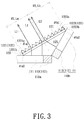
- FIG. 3 is a schematic view of an optical path of a forward light of adjacent two display screens passing through a prism structure optical element according to an embodiment of the invention
- FIG. 4 is a schematic view of a prism structure optical element of a multi-screen display device according to another embodiment of the invention.
- FIG. 5 is a schematic view of the prism structure optical element of FIG. 4 refracting light
- FIG. 6A is an enlarged schematic view of the first prism column in the first region adjacent to the second region in FIG. 5 refracting light;
- FIG. 6B is an enlarged schematic view of the first prism column in the first region adjacent to the display screen in FIG. 5 refracting light;
- FIG. 7 is a schematic view of a viewer viewing a multi-screen display device at different viewing positions
- FIG. 8A is a schematic view of a partial optical path when a viewer is at the viewing position P 1 in FIG. 7 ;
- FIG. 8B is a schematic view of a partial optical path when a viewer is at the viewing position P 2 in FIG. 7 ;
- FIG. 9 is a schematic view of a prism structure optical element of a multi-screen display device refracting light according to another embodiment of the invention.
- FIG. 10A is a schematic view of a partial optical path when a viewer at a preferred position viewing views the display device in FIG. 9 ;
- FIG. 10B is a schematic view of a partial optical path when a viewer is at a relatively far viewing position views the display device in FIG. 9 ;
- FIG. 11 is a schematic view of a prism structure optical element of a multi-screen display device according to another embodiment of the invention.
- the description of “A” component facing “B” component herein may contain the situations that “A” component directly faces “B” component or one or more additional components are between “A” component and “B” component.
- the description of “A” component “adjacent to” “B” component herein may contain the situations that “A” component is directly “adjacent to” “B” component or one or more additional components are between “A” component and “B” component. Accordingly, the drawings and descriptions will be regarded as illustrative in nature and not as restrictive.
- FIG. 1 is a schematic view of a multi-screen display device according to an embodiment of the invention.
- the multi-screen display device 100 of the embodiment includes a prism structure optical element 120 and a plurality of display screens, wherein FIG. 1 illustrates three display screens 110 a , 110 b and 110 c as an example.
- the display screens 110 a , 110 b and 110 c are arranged adjacent to each other.
- An included angle ⁇ 1 is formed between at least adjacent two display screens of the display screens 110 a , 110 b and 110 c , wherein the included angle ⁇ 1 is greater than 90 degrees and less than 180 degrees.
- an included angle ⁇ 1 is formed between the adjacent two display screens 110 a , 110 b , and an included angle ⁇ 1 is also formed between the adjacent two display screens 110 a , 110 c .
- the angle of the included angle ⁇ 1 may be determined according to different design requirements.
- each of the display screens 110 a , 110 b and 110 c has a display area 111 and a border 112 surrounding the display area 111 .
- the display screens 110 a , 110 b and 110 c in the embodiment may be various types of display screens, such as a liquid crystal display screen and an organic light-emitting diode display screen, but not limited thereto.
- the display screens 110 a , 110 b and 110 c may be a flat screen or a curved screen.
- the prism structure optical element 120 is disposed between the adjacent two display screens having the included angle ⁇ 1 , for example, between the display screens 110 a , 110 b and between the display screens 110 a , 110 c . That is, the quantity of the prism structure optical elements 120 may be one or more, and one prism structure optical element 120 may be disposed between any adjacent two display screens having the included angle ⁇ 1 . In other embodiments, it is to determine whether to dispose the prism structure optical element 120 between adjacent two display screens having the included angle ⁇ 1 among the display screens according to design requirements. For example, the prism structure optical element 120 is disposed between the display screens 110 a , 110 b but is not disposed between the display screens 110 a , 110 c .
- each prism structure optical element 120 covers the two side edges 113 adjacent to each other of the two borders 112 and a part of the two display areas 111 of the corresponding adjacent two display screens.
- the prism structure optical element 120 corresponding to the display screens 110 a , 110 b is disposed in a manner of being inclined with respect to the two side edges 113 adjacent to each other of the display screens 110 a , 110 b and a part of the two display areas 111 of the display screens 110 a , 110 b respectively, so as to cover the two side edges 113 adjacent to each other of the two borders 112 of the display screen 110 a , 110 b and a part of the two display areas 111 of the display screens 110 a , 110 b at the same time.
- the prism structure optical element 120 corresponding to the display screens 110 a , 110 c is disposed in a manner of being inclined with respect to the two side edges 113 adjacent to each other of the two borders 112 of the display screens 110 a , 110 c and a part of the two display areas 111 of the display screens 110 a , 110 c respectively, so as to cover the two side edges 113 adjacent to each other of the two borders 112 of the display screen 110 a , 110 c and a part of the two display areas 111 of the display screens 110 a , 110 c at the same time.
- the prism structure optical element 120 corresponding to the display screens 110 a , 110 b is neither parallel nor perpendicular to the display screens 110 a , 110 b and the prism structure optical element 120 corresponding to the displays 110 a , 110 c is neither parallel nor perpendicular to the display screens 110 a , 110 c.
- FIG. 2 is a schematic view of a prism structure optical element of a multi-screen display device according to an embodiment of the invention.
- the prism structure optical element 120 of the embodiment includes a substrate 121 and a plurality of prism columns 122 .
- the prism columns 122 are arranged on the substrate 121 along a predetermined direction D 2 , and the extending direction D 1 of each prism column 122 is substantially parallel to the two side edges 113 adjacent to each other shown in FIG. 1 . That is, each prism column 122 extends from the upper end 123 to the lower end 124 of the prism structure optical element 120 in FIG. 1 .
- the extending direction D 1 of each prism column 122 is parallel to the longitudinal side edge of the display area 111 .
- the substrate 121 includes a first region R 1 and a second region R 2 adjacent to each other.
- the first region R 1 and the second region R 2 respectively correspond to parts of the two display screens 110 a , 110 b or 110 a , 110 c in FIG. 1 .
- the length of the first region R 1 in the predetermined direction D 2 is La
- the length of the second region R 2 in the predetermined direction D 2 is Lb
- the substrate 121 has, for example, a carrier surface 125 that is away from the adjacent two display screens (e.g., away from the display screens 110 a , 110 b or away from the display screens 110 a , 110 c ), that is, the carrier surface 125 faces the viewer.
- the prism columns 122 are disposed on the carrier surface 125 and include a plurality of first prism columns 1221 arranged in the first region R 1 and a plurality of second prism columns 1222 arranged in the second region R 2 .
- Each first prism column 1221 has two interior angles ⁇ a 1 , ⁇ a 2 , a first surface 1221 a and a second surface 1221 b , wherein the two interior angles ⁇ a 1 , ⁇ a 2 are adjacent to the substrate 121 .
- the interior angle ⁇ a 1 is located between the interior angle ⁇ a 2 and the second region R 2
- the interior angle ⁇ a 1 is the included angle between the first surface 1221 a and the substrate 121
- the interior angle ⁇ a 2 is the included angle between the second surface 1221 b and the substrate 121 .
- Each second prism column 1222 has two interior angles ⁇ b 1 , ⁇ b 2 , a third surface 1222 a and a fourth surface 1222 b , wherein the two interior angles ⁇ b 1 , ⁇ b 2 are adjacent to the substrate 121 .
- the interior angle ⁇ b 1 is located between the interior angle ⁇ b 2 and the first region R 1
- the interior angle ⁇ b 1 is the included angle between the third surface 1222 a and the substrate 121
- the interior angle ⁇ b 2 is the included angle between the fourth surface 1222 b and the substrate 121 .
- the substrate 121 of the embodiment is, for example, a film, but the invention does not limit the specific shape of the substrate 121 .
- each prism column 122 of the embodiment is, for example, a triangular prism column, but is not limited thereto.
- FIG. 3 is a schematic view of an optical path of a forward light of adjacent two display screens passing through a prism structure optical element according to an embodiment of the invention.
- the prism structure optical element 120 refracts the light L 1 that is forwardly emitted from the display area 111 of the display screen 110 a and the light L 2 that is forwardly emitted from the display area 111 of the display screen 110 b , and the lights L 1 and L 2 can be also forwardly emitted after passing through the prism structure optical element 120 .
- the light L 1 that is forwardly emitted from the display area 111 of the display screen 110 a is incident on the first prism column 1221 via the substrate 121 , the light L 1 is refracted on the first surface 1221 a to reach the forward light output (i.e., the light is perpendicular to the carrier surface 125 when it is emitted).
- the light L 2 that is emitted from the display area 111 of the display screen 110 b is incident on the second prism column 1222 via the substrate 121 , the light L 2 is refracted on the third surface 1222 a to reach the forward light output.
- the two ends of the prism structure optical element 120 covering parts of the two display areas 111 of the adjacent two display screens 110 a , 110 b are respectively abutted against the display areas 111 of the adjacent two display screens 110 a , 110 b , thereby being stably fixed to the adjacent two display screens 110 a , 110 b (as shown in FIG. 3 ).
- the prism structure optical element 120 can also be fixed by other mechanisms such that the two ends of the prism structure optical element 120 covering parts of the two display areas 111 of the adjacent two display screens 110 a , 110 b are not respectively abutted against the display areas 111 of the adjacent two display screens 110 a , the invention is not limited thereto, and no redundant detail is to be given herein for the following similar figures.
- the regions corresponding to the adjacent two side edges 113 of the two borders 112 of the adjacent two display screens 110 a , 110 b also have the lights L 1 , L 2 transmitted toward the viewer, so the viewer does not see the adjacent two side edges 113 of the two borders 112 of the adjacent two display screens 110 a , 110 b .
- the viewer can see a good stitching image frame when the adjacent two display screens 110 a , 110 b jointly display the image frame due to that the display quality is not affected by the borders 112 .
- the prism structure optical element 120 is also disposed between the adjacent two display screens 110 a and 110 c in FIG. 1 , the display quality is not affected by the borders 112 .
- the first prism column 1221 has a first surface 1221 a and a second surface 1221 b . Since the light L 1 forwardly emitted from a part of the display region 111 of the display screen 110 a covered by the prism structure optical element 120 is emitted from the first surface 1221 a of the first prism column 1221 , the second surface 1221 b corresponding to the first surface 1221 a of the display area 111 of the display screen 110 a is less likely to emit light with higher energy, and thus has a problem of lower brightness. Further, the viewer may perceive a slight ghosting due to that the direction of the light emitted from the second surface 1221 b is different from the direction of the light L 1 emitted from the first surface 1221 a .
- the second prism column 1222 has a third surface 1222 a and a fourth surface 1222 b . Since the light L 2 forwardly emitted from a part of the display region 111 of the display screen 110 b covered by the prism structure optical element 120 is emitted from the third surface 1222 a of the second prism column 1222 , the fourth surface 1222 b corresponding to the third surface 1222 a of the display area 111 of the display screen 110 b is less likely to emit light with higher energy, and thus has a problem of lower brightness. Further, the viewer may perceive a slight ghosting due to that the direction of the light emitted from the fourth surface 1222 b is different from the direction of the light L 2 emitted from the third surface 1222 a.
- the prism structure optical element 120 of the embodiment has the following designs: the relationship between the two interior angles ⁇ a 1 , ⁇ a 2 of each first prism column 1221 is ⁇ a 1 ⁇ a 2 ; the relationship between the two interior angles ⁇ b 1 , ⁇ b 2 of each second prism column 1222 is ⁇ b 1 ⁇ b 2 ; the angles of the interior angles ⁇ a 1 , ⁇ a 2 of the first prism column 1221 are the same; and the angles of the interior angles ⁇ b 1 , ⁇ b 2 of the second prism column 1222 are the same.
- each prism structure optical element 120 corresponds to, for example, the display screen 110 a located in the middle among the display screens 110 a , 110 b and 110 c in FIG. 1 .
- the prism column 122 is, for example, a triangular prism column, and the interior angles ⁇ a 1 , ⁇ a 2 , ⁇ b 1 , and ⁇ b 2 also satisfy the following relationship: 40° ⁇ a 1 ⁇ 70°, 60° ⁇ a 2 ⁇ 90°, 40° ⁇ b 1 ⁇ 70° and 60° ⁇ b 2 ⁇ 90°.
- the orthographic projection area of the first surface 1221 a adjacent to the interior angle ⁇ a 1 on the substrate 121 is larger than the orthographic projection area of the second surface 1221 b adjacent to the interior angle ⁇ a 2 on the substrate 121 . Therefore, most of the light L 1 forward emitted from the display area 111 of the display screen 110 a can exit from the first surface 1221 a , and thus not only increasing the brightness but also improving the ghosting caused by the light exiting from the second surface 1221 b .
- the orthographic projection area of the third surface 1221 a adjacent to the interior angle ⁇ b 1 on the substrate 121 is larger than the orthographic projection area of the fourth surface 1222 b adjacent to the interior angle ⁇ b 2 on the substrate 121 . Therefore, most of the light L 2 emitted forward from the display area 111 of the display screen 110 b can exit from the third surface 1222 a , and thus not only increasing the brightness but also improving the ghosting caused by the light exiting from the fourth surface 1222 b.
- the prism structure optical element 120 of the embodiment can also design the roughness of the second surface 1221 b and the fourth surface 1222 b to be larger than the roughness of the first surface 1221 a and the third surface 1222 a . Since the second surface 1221 b and the fourth surface 1222 b have a higher roughness, the light passing through the second surface 1221 b and the fourth surface 1222 b can be diverged, so as to reduce the ghosting caused by the light L 1 passing through the second surface 1221 b and the light L 2 passing through the fourth surface 1222 b .
- at least one of the second surface 1221 b and the fourth surface 1222 b is designed as a light absorbing surface.
- a light absorbing material (not shown) is disposed on the second surfaces 1221 b and the fourth surface 1222 b by screen printing, inkjet, exposure development, or the like, thereby achieving the effect of light absorbing and avoiding ghosting caused by the light L 1 , L 2 respectively emitted from the second surface 1221 b and the fourth surface 1222 b.
- FIG. 4 is a schematic view of a prism structure optical element of a multi-screen display device according to another embodiment of the invention.
- FIG. 5 is a schematic view of the prism structure optical element of FIG. 4 refracting light.
- the prism structure optical element 120 a of the embodiment is similar to the prism structure optical element 120 in structure and advantages, and only the main differences of the structure will be described below.
- the interior angles ⁇ a 1 of the first prism columns 1221 are gradually decreased from the boundary between the first region R 1 and the second region R 2 toward the direction away from the second region R 2
- the interior angles ⁇ b 1 of the prism columns 1222 are gradually decreased from the boundary between the first region R 1 and the second region R 2 toward the direction away from the first region R 1
- the angles of ⁇ a 1 , ⁇ b 1 are, for example, 0° ⁇ a 1 ⁇ 70° and 0° ⁇ b 1 ⁇ 70°.
- the more common design is 45° ⁇ a 1 ⁇ 60° and 45° ⁇ b 1 ⁇ 60°.
- the quantity of the first prism column 1221 and the second prism column 1222 each in FIG.
- the relationships of the plurality of interior angles ⁇ a 1 ⁇ 1, ⁇ a 1 ⁇ 2, ⁇ a 1 ⁇ 3, ⁇ a 1 ⁇ 4, ⁇ a 1 ⁇ 5, ⁇ a 1 ⁇ 6 of the plurality of first prism columns 1221 is ⁇ a 1 ⁇ 1 ⁇ a 1 ⁇ 2 ⁇ a 1 ⁇ 3 ⁇ a 1 ⁇ 4 ⁇ a 1 ⁇ 5 ⁇ a 1 ⁇ 6 and ⁇ a 1 ⁇ 1> ⁇ a 1 ⁇ 6.
- the above description is also applicable to a plurality of interior angles ⁇ b 1 ⁇ 1, ⁇ b 1 ⁇ 2, ⁇ b 1 ⁇ 3, ⁇ b 1 ⁇ 4, ⁇ b 1 ⁇ 5, ⁇ b 1 ⁇ 6 of the plurality of second prism columns 1222 , that is, ⁇ b 1 ⁇ 1 ⁇ b 1 ⁇ 2 ⁇ b 1 ⁇ 3 ⁇ b 1 ⁇ 4 ⁇ b 1 ⁇ 5 ⁇ b 1 ⁇ 6, and ⁇ b 1 ⁇ 1> ⁇ b 1 ⁇ 6.
- FIG. 6A is an enlarged schematic view of the first prism column in the first region adjacent to the second region in FIG. 5 refracting light.
- FIG. 6B is an enlarged schematic view of the first prism column in the first region adjacent to the display screen in FIG. 5 refracting light.
- the light L 3 is emitted from the display screen 110 a at the light exit angle ⁇ 3 , and then is incident on the first prism column 1221 in the first region R 1 of the prism structure optical element 120 a adjacent to the second region R 2 , and then is forwardly emitted from the prism structure optical element 120 a after being refracted.
- the light L 4 is emitted from the display screen 110 a at the light exit angle ⁇ 4 , and then is incident on the first prism column 1221 in the first region R 1 of the prism structure optical element 120 a adjacent to the display screen 110 a , and then is forwardly emitted from the prism structure optical element 120 a after being refracted.
- the light exit angle ⁇ 3 is greater than the light exit angle ⁇ 4 under the aforementioned design of the first prism column 1221 (e.g., ⁇ a 1 ⁇ 1> ⁇ a 1 ⁇ 6).
- the light having a larger light exit angle has a lower brightness (e.g., the brightness of the light L 4 is greater than the brightness of the light L 3 ) due to that the forwardly-emitting light has the highest brightness under the design of the display screen 110 a .
- the change in brightness exhibited by the light emitted from the first region R 1 of the prism structure optical element 120 a is gradually decreased in the direction away from the second region R 2 toward the second region R 2 (direction A 1 in FIG. 5A ).
- the change in brightness exhibited by the light emitted from the second region R 2 of the prism structure optical element 120 a is gradually decreased in the direction away from the first region R 1 toward the first region R 1 (direction A 2 in FIG. 5A ).
- the brightness of the light emitted from the display screens 110 a , 110 b is higher than the brightness of the light emitted from the prism structure optical element 120 a , the brightness of the light emitted from the prism structure optical element 120 a is gradually decreased from both ends of the display screens 110 a , 110 b to the middle thereof.
- the viewer is less likely to perceive the difference in brightness of the image frame displayed by the display screens 110 a , 110 b and the prism structure optical element 120 a .
- the viewer is less likely to perceive the difference in brightness of the aforementioned image frame when the prism structure optical element 120 a is disposed between the display screens 110 a , 110 c.
- FIG. 7 is a schematic view of a viewer viewing a multi-screen display device at different viewing positions.
- FIG. 8A is a schematic view of a partial optical path when a viewer is at the viewing position P 1 in FIG. 7 .
- FIG. 8B is a schematic view of a partial optical path when a viewer is at the viewing position P 2 in FIG. 7 .
- the multi-screen display device 100 a of the embodiment employs two prism structure optical elements 120 of FIG. 2 , and there is a preferred viewing position P 1 at the center line C of the display screen 110 a .
- the light L 5 , L 6 in FIG. 8A are substantially parallel to the viewing direction D 3 of the viewer in FIG.
- the viewer receives the lights L 5 , L 6 , wherein the light L 5 is from the display area 111 of the display screen 110 a and is refracted to the viewer via the first region R 1 of the prism structure optical element 120 adjacent to the second region R 2 , while the light L 6 is from the display area 111 of the display screen 110 b and is refracted to the viewer via the second region R 2 of the prism structure optical element 120 adjacent to the first region R 1 . Therefore, the two side edges 113 adjacent to each other of the two borders 112 of the display screens 110 a , 110 b are not viewed even if the viewer views toward the boundary of the first region R 1 and the second region R 2 .
- the viewing direction changes when the viewer is at the viewing position P 2 which is relatively far from the display screen 110 a
- the lights L 7 , L 8 , and L 9 in FIG. 8B are substantially parallel to the viewing direction D 4 of the viewer in FIG. 7 .
- the viewer receives the lights L 7 , L 8 and L 9 , wherein the light L 7 is from the display area 111 of the display screen 110 a and is refracted to the viewer via the first region R 1 of the prism structure optical element 120 adjacent to the second region R 2
- the light L 9 is from the display area 111 of the display screen 110 b and is refracted to the viewer via the second region R 2 of the prism structure optical element 120 .
- the light L 9 is from the edge of the display area 111 of the display screen 110 b but it is not refracted to the viewer via the second region R 2 of the prism structure optical element 120 adjacent to the first region R 1 .
- the light L 8 refracted to the viewer via the second region R 2 of the prism structure optical element 120 adjacent to the first region R 1 is from the side edge 113 of the border 112 of the display screen 112 adjacent to the display screen 110 a , therefore, the viewer may view the side edge 113 of the border 112 of the display screen 110 b adjacent to the display screen 110 a .
- the viewer may also view the side edge 113 of the border 112 of the display screen 110 c adjacent to the display screen 110 a.
- the length La of the first region R 1 of the substrate 121 b of the prism structure optical element 120 b in the predetermined direction D 2 is designed to be larger than the length Lb of the second region R 2 in the predetermined direction D 2 .
- the first region R 1 also corresponds to a part of the other of the two display screens 110 a , 110 b . Taking FIG. 9 as an example.
- the first region R 1 of the prism structure optical element 120 b covering the display screens 110 a , 110 b also corresponds to a part of the display screen 110 b .
- the first region R 1 of the prism structure optical element 120 b covering the display screens 110 a , 110 c in FIG. 7 also corresponds to a part of the display screen 110 c .
- the length La and the length Lb satisfy, for example, the relationship: 1 ⁇ La/Lb ⁇ 1.2.
- FIG. 10A is a schematic view of a partial optical path when a viewer at a preferred position viewing views the display device in FIG. 9 .
- FIG. 10B is a schematic view of a partial optical path when a viewer is at a relatively far viewing position views the display device in FIG. 9 .
- the lights L 10 , L 11 are substantially parallel to the viewing direction of the viewer.
- the viewer receives the lights L 10 , L 11 , wherein the light L 10 is from the display area 111 of the display screen 110 a and is refracted to the viewer via the first region R 1 of the prism structure optical element 120 b adjacent to the second region R 2 , while the light L 11 is from the display area 111 of the display screen 110 b and is refracted to the viewer via the second region R 2 of the prism structure optical element 120 b adjacent to the first region R 1 . Therefore, the two side edges 113 adjacent to each other of the two borders 112 of the display screens 110 a , 110 b are not viewed even if the viewer views toward the boundary of the first region R 1 and the second region R 2 .
- the viewing direction changes when the viewer is at a viewing position which is relatively far from the display screen 110 a than the preferred viewing position, and the lights L 12 , L 13 are substantially parallel to the viewing direction of the viewer.
- the viewer receives the lights L 12 , L 13 , wherein the light L 12 is from the display area 111 of the display screen 110 a and is refracted to the viewer via the first region R 1 of the prism structure optical element 120 b adjacent to the second region R 2 , the light L 13 is from the display area 111 of the display screen 110 b and is refracted to the viewer via the second region R 2 of the prism structure optical element 120 b . Therefore, the two side edges 113 adjacent to each other of the two borders 112 of the display screens 110 a , 110 b are not viewed even if the viewer views toward the boundary of the first region R 1 and the second region R 2 .
- FIG. 11 is a schematic view of a prism structure optical element of a multi-screen display device according to another embodiment of the invention.
- the prism structure optical element 120 c of the embodiment is similar to the prism structure optical element 120 of FIG. 2 .
- the main difference is that the prism structure optical element 120 c further includes a polarizing absorbing material layer 130 disposed on the substrate 121 .
- the polarizing absorbing material layer 130 is disposed, for example, on a surface 126 of the substrate 121 that is away from the prism columns 122 . In other embodiments, the polarizing absorbing material layer 130 may be disposed between the prism columns 122 and the substrate 121 .
- the polarizing absorbing material layer 130 can reduce the reflected light formed by the ambient light source.
- the display screens 110 a , 110 b and 110 c of FIG. 1 are display screens having an upper polarizer (e.g., a liquid crystal display screen)
- the polarization direction of the polarizing absorbing material layer 130 is the same as the polarization direction of the upper polarizer.
- the transmission axis of the polarizing absorbing material layer 130 is parallel to the transmission axis of the upper polarizer.
- the polarizing absorbing material layer 130 can be applied to the prism structure optical element of each embodiment of the invention.
- the multi-screen display device of the embodiment of the invention has a prism structure optical element which covers adjacent two side edges of the two borders and a part of the display areas of the adjacent two display screens.
- the prism structure optical element can guide the light emitted from the part of the display area covered by the prism structure optical element to the viewer's eyes. As such, the viewer is less likely to perceive the borders and the prism structure optical element between the adjacent two display screens when viewing the stitching image frame formed by the plurality of display screens.
- the ghosting caused by the light passing through the second surface and the fourth surface can be reduced by making the second surface and/or the fourth surface of the prism column as a light absorbing surface or making the roughness of the second surface and the fourth surface larger than the roughness of the first surface and the third surface.
Landscapes
- Physics & Mathematics (AREA)
- General Physics & Mathematics (AREA)
- Engineering & Computer Science (AREA)
- Optics & Photonics (AREA)
- Theoretical Computer Science (AREA)
- General Engineering & Computer Science (AREA)
- Multimedia (AREA)
- Computer Hardware Design (AREA)
- Human Computer Interaction (AREA)
- Devices For Indicating Variable Information By Combining Individual Elements (AREA)
- Optical Elements Other Than Lenses (AREA)
Applications Claiming Priority (2)
| Application Number | Priority Date | Filing Date | Title |
|---|---|---|---|
| CN201910193139.5A CN111696446B (zh) | 2019-03-14 | 2019-03-14 | 多荧幕显示装置 |
| CN201910193139.5 | 2019-03-14 |
Publications (2)
| Publication Number | Publication Date |
|---|---|
| US20200293087A1 US20200293087A1 (en) | 2020-09-17 |
| US10955874B2 true US10955874B2 (en) | 2021-03-23 |
Family
ID=72176064
Family Applications (1)
| Application Number | Title | Priority Date | Filing Date |
|---|---|---|---|
| US16/817,640 Active US10955874B2 (en) | 2019-03-14 | 2020-03-13 | Multi-screen display device |
Country Status (3)
| Country | Link |
|---|---|
| US (1) | US10955874B2 (zh) |
| CN (1) | CN111696446B (zh) |
| TW (1) | TWI695191B (zh) |
Cited By (1)
| Publication number | Priority date | Publication date | Assignee | Title |
|---|---|---|---|---|
| US11054553B2 (en) * | 2019-02-18 | 2021-07-06 | Champ Vision Display Inc. | Display apparatus with multi screens |
Families Citing this family (3)
| Publication number | Priority date | Publication date | Assignee | Title |
|---|---|---|---|---|
| CN111724689A (zh) * | 2019-03-22 | 2020-09-29 | 咏巨科技有限公司 | 显示装置及其透镜结构 |
| TWD204680S (zh) * | 2019-10-31 | 2020-05-11 | 廣達電腦股份有限公司 | 筆記型電腦 |
| TWD204679S (zh) * | 2019-10-31 | 2020-05-11 | 廣達電腦股份有限公司 | 筆記型電腦 |
Citations (8)
| Publication number | Priority date | Publication date | Assignee | Title |
|---|---|---|---|---|
| US20100277665A1 (en) * | 2009-04-30 | 2010-11-04 | Au Optronics Corporation | Display Device with Multiple Display Modules |
| US20110164200A1 (en) * | 2008-08-04 | 2011-07-07 | Sharp Kabushiki Kaisha | Display device |
| US20110279487A1 (en) * | 2009-05-29 | 2011-11-17 | Sharp Kabushiki Kaisha | Display device and display method |
| US9103524B2 (en) * | 2012-11-02 | 2015-08-11 | Corning Incorporated | Immersive display with minimized image artifacts |
| US20180040281A1 (en) * | 2016-08-08 | 2018-02-08 | Young Lighting Technology Inc. | Display apparatus with multi screens and display signal control method thereof |
| CN108766255A (zh) | 2018-08-16 | 2018-11-06 | 深圳市眸合科技有限公司 | 一种多屏幕无缝拼接显示系统 |
| TWI642050B (zh) | 2017-10-25 | 2018-11-21 | 誠屏科技股份有限公司 | 多螢幕顯示裝置 |
| US20190258444A1 (en) | 2018-02-22 | 2019-08-22 | Champ Vision Display Inc. | Multi-screen display apparatus and display method thereof |
Family Cites Families (15)
| Publication number | Priority date | Publication date | Assignee | Title |
|---|---|---|---|---|
| JP2005321693A (ja) * | 2004-05-11 | 2005-11-17 | Hitachi Displays Ltd | 液晶表示装置 |
| CN101280905B (zh) * | 2008-05-13 | 2010-12-22 | 友达光电股份有限公司 | 具可遮蔽外框的显示装置及其使用的导光器件 |
| TWI365325B (en) * | 2008-10-31 | 2012-06-01 | Au Optronics Corp | Display apparatus |
| CN102637388B (zh) * | 2012-04-28 | 2013-12-25 | 广东威创视讯科技股份有限公司 | 一种无缝拼接显示屏 |
| CN103093706B (zh) * | 2013-01-29 | 2016-02-03 | 京东方科技集团股份有限公司 | 显示屏及拼接显示屏 |
| US9121999B2 (en) * | 2013-07-30 | 2015-09-01 | Au Optronics Corporation | Optical film and display device having the same |
| KR102328532B1 (ko) * | 2013-12-03 | 2021-11-18 | 엘지전자 주식회사 | 멀티 스크린 디스플레이 장치 |
| JP2016018108A (ja) * | 2014-07-09 | 2016-02-01 | 国立大学法人 筑波大学 | 裸眼立体映像表示装置 |
| CN105448196B (zh) * | 2015-12-21 | 2018-08-17 | 曹嘉灿 | 一种消隐边框显示装置及显示器 |
| JP2018041717A (ja) * | 2016-08-31 | 2018-03-15 | 大日本印刷株式会社 | 面光源装置および表示装置 |
| KR20180071657A (ko) * | 2016-12-20 | 2018-06-28 | 엘지디스플레이 주식회사 | 표시 장치와 이를 포함하는 멀티 스크린 표시 장치 |
| CN108469642B (zh) * | 2018-03-29 | 2021-03-12 | 京东方科技集团股份有限公司 | 一种棱镜膜、背光模组及显示装置 |
| CN208507134U (zh) * | 2018-07-04 | 2019-02-15 | 弘胜光电股份有限公司 | 光学装置及其光学结构体 |
| CN109212660B (zh) * | 2018-10-26 | 2020-01-24 | 合肥京东方光电科技有限公司 | 导光组件、光准直组件、背光模组及显示装置 |
| CN109377891A (zh) * | 2018-11-21 | 2019-02-22 | 福建捷联电子有限公司 | 一种无缝拼接显示器 |
-
2019
- 2019-03-14 CN CN201910193139.5A patent/CN111696446B/zh active Active
- 2019-03-22 TW TW108110023A patent/TWI695191B/zh active
-
2020
- 2020-03-13 US US16/817,640 patent/US10955874B2/en active Active
Patent Citations (10)
| Publication number | Priority date | Publication date | Assignee | Title |
|---|---|---|---|---|
| US20110164200A1 (en) * | 2008-08-04 | 2011-07-07 | Sharp Kabushiki Kaisha | Display device |
| US20100277665A1 (en) * | 2009-04-30 | 2010-11-04 | Au Optronics Corporation | Display Device with Multiple Display Modules |
| TWI411848B (zh) | 2009-04-30 | 2013-10-11 | Au Optronics Corp | 具複數顯示模組之顯示裝置 |
| US20110279487A1 (en) * | 2009-05-29 | 2011-11-17 | Sharp Kabushiki Kaisha | Display device and display method |
| US9103524B2 (en) * | 2012-11-02 | 2015-08-11 | Corning Incorporated | Immersive display with minimized image artifacts |
| US20180040281A1 (en) * | 2016-08-08 | 2018-02-08 | Young Lighting Technology Inc. | Display apparatus with multi screens and display signal control method thereof |
| TWI642050B (zh) | 2017-10-25 | 2018-11-21 | 誠屏科技股份有限公司 | 多螢幕顯示裝置 |
| US20190121593A1 (en) | 2017-10-25 | 2019-04-25 | Champ Vision Display Inc. | Multi-screen display device |
| US20190258444A1 (en) | 2018-02-22 | 2019-08-22 | Champ Vision Display Inc. | Multi-screen display apparatus and display method thereof |
| CN108766255A (zh) | 2018-08-16 | 2018-11-06 | 深圳市眸合科技有限公司 | 一种多屏幕无缝拼接显示系统 |
Cited By (1)
| Publication number | Priority date | Publication date | Assignee | Title |
|---|---|---|---|---|
| US11054553B2 (en) * | 2019-02-18 | 2021-07-06 | Champ Vision Display Inc. | Display apparatus with multi screens |
Also Published As
| Publication number | Publication date |
|---|---|
| CN111696446B (zh) | 2023-08-04 |
| US20200293087A1 (en) | 2020-09-17 |
| TW202033987A (zh) | 2020-09-16 |
| TWI695191B (zh) | 2020-06-01 |
| CN111696446A (zh) | 2020-09-22 |
Similar Documents
| Publication | Publication Date | Title |
|---|---|---|
| US10955874B2 (en) | Multi-screen display device | |
| US8514343B2 (en) | Beam splitting film, backlight module, and stereo display apparatus | |
| US10929086B2 (en) | Multi-screen display apparatus and display method thereof | |
| TW516328B (en) | Illumination device, picture display device using the same, liquid crystal television, liquid crystal monitor and liquid crystal information terminal equipment | |
| TWI228196B (en) | Liquid crystal display device and electronic apparatus | |
| US10504451B2 (en) | Display apparatus with multi screens and display signal control method thereof | |
| US10809959B2 (en) | Multi-screen display device | |
| US20190293974A1 (en) | Anti-peeping control device and backlight module and display using same | |
| US20230288724A1 (en) | Aerial floating image information display system and light source apparatus used in the same | |
| US20090027593A1 (en) | Liquid crystal display device having a prism sheet between first and second light diffusion | |
| TWM551279U (zh) | 顯示裝置 | |
| CN110632688B (zh) | 光扩散控制层叠体及反射型显示体 | |
| TWI428632B (zh) | 立體影像顯示器 | |
| JP2009059498A (ja) | 照明装置および液晶表示装置 | |
| WO2022198679A1 (zh) | 拼接显示单元和显示屏 | |
| TWI422871B (zh) | 光學元件及顯示模組 | |
| JP2020013067A (ja) | 光学構造体および表示装置 | |
| US20110037923A1 (en) | Light condensing film, backlight module and liquid crystal display | |
| US11054553B2 (en) | Display apparatus with multi screens | |
| US10082608B2 (en) | Prism group and display apparatus using the same | |
| JP4103357B2 (ja) | 反射型液晶表示装置、およびこれを用いた情報機器 | |
| US9311869B2 (en) | Display system | |
| JPH09179113A (ja) | 液晶表示装置 | |
| US20240295686A1 (en) | Backlight module and display device | |
| JPH1039286A (ja) | 液晶表示装置 |
Legal Events
| Date | Code | Title | Description |
|---|---|---|---|
| AS | Assignment |
Owner name: CHAMP VISION DISPLAY INC., TAIWAN Free format text: ASSIGNMENT OF ASSIGNORS INTEREST;ASSIGNORS:LIU, CHIN-KU;WU, CHUNG-HAO;REEL/FRAME:052103/0801 Effective date: 20190328 |
|
| FEPP | Fee payment procedure |
Free format text: ENTITY STATUS SET TO UNDISCOUNTED (ORIGINAL EVENT CODE: BIG.); ENTITY STATUS OF PATENT OWNER: LARGE ENTITY |
|
| STPP | Information on status: patent application and granting procedure in general |
Free format text: NOTICE OF ALLOWANCE MAILED -- APPLICATION RECEIVED IN OFFICE OF PUBLICATIONS |
|
| STCF | Information on status: patent grant |
Free format text: PATENTED CASE |
|
| MAFP | Maintenance fee payment |
Free format text: PAYMENT OF MAINTENANCE FEE, 4TH YEAR, LARGE ENTITY (ORIGINAL EVENT CODE: M1551); ENTITY STATUS OF PATENT OWNER: LARGE ENTITY Year of fee payment: 4 |