US10926701B2 - Parking assistance method and parking assistance device - Google Patents
Parking assistance method and parking assistance device Download PDFInfo
- Publication number
- US10926701B2 US10926701B2 US16/625,490 US201716625490A US10926701B2 US 10926701 B2 US10926701 B2 US 10926701B2 US 201716625490 A US201716625490 A US 201716625490A US 10926701 B2 US10926701 B2 US 10926701B2
- Authority
- US
- United States
- Prior art keywords
- image
- assistance
- parking
- turning
- mobile object
- Prior art date
- Legal status (The legal status is an assumption and is not a legal conclusion. Google has not performed a legal analysis and makes no representation as to the accuracy of the status listed.)
- Active
Links
- 238000000034 method Methods 0.000 title claims description 41
- 230000008859 change Effects 0.000 claims description 2
- 239000000203 mixture Substances 0.000 description 47
- 230000008569 process Effects 0.000 description 18
- 238000004364 calculation method Methods 0.000 description 7
- 238000001514 detection method Methods 0.000 description 6
- 238000010586 diagram Methods 0.000 description 5
- 230000001133 acceleration Effects 0.000 description 2
- 230000008901 benefit Effects 0.000 description 2
- 230000006870 function Effects 0.000 description 2
- 238000004140 cleaning Methods 0.000 description 1
- 238000004891 communication Methods 0.000 description 1
- 230000000295 complement effect Effects 0.000 description 1
- 239000002131 composite material Substances 0.000 description 1
- 238000004590 computer program Methods 0.000 description 1
- 239000000470 constituent Substances 0.000 description 1
- 229910044991 metal oxide Inorganic materials 0.000 description 1
- 150000004706 metal oxides Chemical class 0.000 description 1
- 239000000523 sample Substances 0.000 description 1
- 239000004065 semiconductor Substances 0.000 description 1
Images


Classifications
-
- B—PERFORMING OPERATIONS; TRANSPORTING
- B60—VEHICLES IN GENERAL
- B60R—VEHICLES, VEHICLE FITTINGS, OR VEHICLE PARTS, NOT OTHERWISE PROVIDED FOR
- B60R21/00—Arrangements or fittings on vehicles for protecting or preventing injuries to occupants or pedestrians in case of accidents or other traffic risks
-
- B—PERFORMING OPERATIONS; TRANSPORTING
- B60—VEHICLES IN GENERAL
- B60W—CONJOINT CONTROL OF VEHICLE SUB-UNITS OF DIFFERENT TYPE OR DIFFERENT FUNCTION; CONTROL SYSTEMS SPECIALLY ADAPTED FOR HYBRID VEHICLES; ROAD VEHICLE DRIVE CONTROL SYSTEMS FOR PURPOSES NOT RELATED TO THE CONTROL OF A PARTICULAR SUB-UNIT
- B60W30/00—Purposes of road vehicle drive control systems not related to the control of a particular sub-unit, e.g. of systems using conjoint control of vehicle sub-units
- B60W30/06—Automatic manoeuvring for parking
-
- B—PERFORMING OPERATIONS; TRANSPORTING
- B60—VEHICLES IN GENERAL
- B60R—VEHICLES, VEHICLE FITTINGS, OR VEHICLE PARTS, NOT OTHERWISE PROVIDED FOR
- B60R1/00—Optical viewing arrangements; Real-time viewing arrangements for drivers or passengers using optical image capturing systems, e.g. cameras or video systems specially adapted for use in or on vehicles
-
- B—PERFORMING OPERATIONS; TRANSPORTING
- B60—VEHICLES IN GENERAL
- B60K—ARRANGEMENT OR MOUNTING OF PROPULSION UNITS OR OF TRANSMISSIONS IN VEHICLES; ARRANGEMENT OR MOUNTING OF PLURAL DIVERSE PRIME-MOVERS IN VEHICLES; AUXILIARY DRIVES FOR VEHICLES; INSTRUMENTATION OR DASHBOARDS FOR VEHICLES; ARRANGEMENTS IN CONNECTION WITH COOLING, AIR INTAKE, GAS EXHAUST OR FUEL SUPPLY OF PROPULSION UNITS IN VEHICLES
- B60K35/00—Instruments specially adapted for vehicles; Arrangement of instruments in or on vehicles
- B60K35/20—Output arrangements, i.e. from vehicle to user, associated with vehicle functions or specially adapted therefor
- B60K35/21—Output arrangements, i.e. from vehicle to user, associated with vehicle functions or specially adapted therefor using visual output, e.g. blinking lights or matrix displays
- B60K35/22—Display screens
-
- B—PERFORMING OPERATIONS; TRANSPORTING
- B60—VEHICLES IN GENERAL
- B60R—VEHICLES, VEHICLE FITTINGS, OR VEHICLE PARTS, NOT OTHERWISE PROVIDED FOR
- B60R1/00—Optical viewing arrangements; Real-time viewing arrangements for drivers or passengers using optical image capturing systems, e.g. cameras or video systems specially adapted for use in or on vehicles
- B60R1/20—Real-time viewing arrangements for drivers or passengers using optical image capturing systems, e.g. cameras or video systems specially adapted for use in or on vehicles
- B60R1/22—Real-time viewing arrangements for drivers or passengers using optical image capturing systems, e.g. cameras or video systems specially adapted for use in or on vehicles for viewing an area outside the vehicle, e.g. the exterior of the vehicle
- B60R1/23—Real-time viewing arrangements for drivers or passengers using optical image capturing systems, e.g. cameras or video systems specially adapted for use in or on vehicles for viewing an area outside the vehicle, e.g. the exterior of the vehicle with a predetermined field of view
- B60R1/27—Real-time viewing arrangements for drivers or passengers using optical image capturing systems, e.g. cameras or video systems specially adapted for use in or on vehicles for viewing an area outside the vehicle, e.g. the exterior of the vehicle with a predetermined field of view providing all-round vision, e.g. using omnidirectional cameras
-
- B—PERFORMING OPERATIONS; TRANSPORTING
- B60—VEHICLES IN GENERAL
- B60W—CONJOINT CONTROL OF VEHICLE SUB-UNITS OF DIFFERENT TYPE OR DIFFERENT FUNCTION; CONTROL SYSTEMS SPECIALLY ADAPTED FOR HYBRID VEHICLES; ROAD VEHICLE DRIVE CONTROL SYSTEMS FOR PURPOSES NOT RELATED TO THE CONTROL OF A PARTICULAR SUB-UNIT
- B60W30/00—Purposes of road vehicle drive control systems not related to the control of a particular sub-unit, e.g. of systems using conjoint control of vehicle sub-units
- B60W30/02—Control of vehicle driving stability
- B60W30/045—Improving turning performance
-
- B—PERFORMING OPERATIONS; TRANSPORTING
- B60—VEHICLES IN GENERAL
- B60W—CONJOINT CONTROL OF VEHICLE SUB-UNITS OF DIFFERENT TYPE OR DIFFERENT FUNCTION; CONTROL SYSTEMS SPECIALLY ADAPTED FOR HYBRID VEHICLES; ROAD VEHICLE DRIVE CONTROL SYSTEMS FOR PURPOSES NOT RELATED TO THE CONTROL OF A PARTICULAR SUB-UNIT
- B60W40/00—Estimation or calculation of non-directly measurable driving parameters for road vehicle drive control systems not related to the control of a particular sub unit, e.g. by using mathematical models
- B60W40/02—Estimation or calculation of non-directly measurable driving parameters for road vehicle drive control systems not related to the control of a particular sub unit, e.g. by using mathematical models related to ambient conditions
-
- B—PERFORMING OPERATIONS; TRANSPORTING
- B60—VEHICLES IN GENERAL
- B60W—CONJOINT CONTROL OF VEHICLE SUB-UNITS OF DIFFERENT TYPE OR DIFFERENT FUNCTION; CONTROL SYSTEMS SPECIALLY ADAPTED FOR HYBRID VEHICLES; ROAD VEHICLE DRIVE CONTROL SYSTEMS FOR PURPOSES NOT RELATED TO THE CONTROL OF A PARTICULAR SUB-UNIT
- B60W40/00—Estimation or calculation of non-directly measurable driving parameters for road vehicle drive control systems not related to the control of a particular sub unit, e.g. by using mathematical models
- B60W40/10—Estimation or calculation of non-directly measurable driving parameters for road vehicle drive control systems not related to the control of a particular sub unit, e.g. by using mathematical models related to vehicle motion
- B60W40/105—Speed
-
- B—PERFORMING OPERATIONS; TRANSPORTING
- B60—VEHICLES IN GENERAL
- B60W—CONJOINT CONTROL OF VEHICLE SUB-UNITS OF DIFFERENT TYPE OR DIFFERENT FUNCTION; CONTROL SYSTEMS SPECIALLY ADAPTED FOR HYBRID VEHICLES; ROAD VEHICLE DRIVE CONTROL SYSTEMS FOR PURPOSES NOT RELATED TO THE CONTROL OF A PARTICULAR SUB-UNIT
- B60W50/00—Details of control systems for road vehicle drive control not related to the control of a particular sub-unit, e.g. process diagnostic or vehicle driver interfaces
- B60W50/08—Interaction between the driver and the control system
- B60W50/14—Means for informing the driver, warning the driver or prompting a driver intervention
-
- B—PERFORMING OPERATIONS; TRANSPORTING
- B62—LAND VEHICLES FOR TRAVELLING OTHERWISE THAN ON RAILS
- B62D—MOTOR VEHICLES; TRAILERS
- B62D15/00—Steering not otherwise provided for
- B62D15/02—Steering position indicators ; Steering position determination; Steering aids
- B62D15/027—Parking aids, e.g. instruction means
- B62D15/0285—Parking performed automatically
-
- G06K9/00812—
-
- G—PHYSICS
- G06—COMPUTING; CALCULATING OR COUNTING
- G06V—IMAGE OR VIDEO RECOGNITION OR UNDERSTANDING
- G06V20/00—Scenes; Scene-specific elements
- G06V20/50—Context or environment of the image
- G06V20/56—Context or environment of the image exterior to a vehicle by using sensors mounted on the vehicle
- G06V20/58—Recognition of moving objects or obstacles, e.g. vehicles or pedestrians; Recognition of traffic objects, e.g. traffic signs, traffic lights or roads
- G06V20/586—Recognition of moving objects or obstacles, e.g. vehicles or pedestrians; Recognition of traffic objects, e.g. traffic signs, traffic lights or roads of parking space
-
- G—PHYSICS
- G08—SIGNALLING
- G08G—TRAFFIC CONTROL SYSTEMS
- G08G1/00—Traffic control systems for road vehicles
- G08G1/01—Detecting movement of traffic to be counted or controlled
- G08G1/056—Detecting movement of traffic to be counted or controlled with provision for distinguishing direction of travel
-
- G—PHYSICS
- G08—SIGNALLING
- G08G—TRAFFIC CONTROL SYSTEMS
- G08G1/00—Traffic control systems for road vehicles
- G08G1/14—Traffic control systems for road vehicles indicating individual free spaces in parking areas
- G08G1/141—Traffic control systems for road vehicles indicating individual free spaces in parking areas with means giving the indication of available parking spaces
- G08G1/143—Traffic control systems for road vehicles indicating individual free spaces in parking areas with means giving the indication of available parking spaces inside the vehicles
-
- G—PHYSICS
- G08—SIGNALLING
- G08G—TRAFFIC CONTROL SYSTEMS
- G08G1/00—Traffic control systems for road vehicles
- G08G1/16—Anti-collision systems
- G08G1/168—Driving aids for parking, e.g. acoustic or visual feedback on parking space
-
- B—PERFORMING OPERATIONS; TRANSPORTING
- B60—VEHICLES IN GENERAL
- B60R—VEHICLES, VEHICLE FITTINGS, OR VEHICLE PARTS, NOT OTHERWISE PROVIDED FOR
- B60R2300/00—Details of viewing arrangements using cameras and displays, specially adapted for use in a vehicle
- B60R2300/10—Details of viewing arrangements using cameras and displays, specially adapted for use in a vehicle characterised by the type of camera system used
- B60R2300/105—Details of viewing arrangements using cameras and displays, specially adapted for use in a vehicle characterised by the type of camera system used using multiple cameras
-
- B—PERFORMING OPERATIONS; TRANSPORTING
- B60—VEHICLES IN GENERAL
- B60R—VEHICLES, VEHICLE FITTINGS, OR VEHICLE PARTS, NOT OTHERWISE PROVIDED FOR
- B60R2300/00—Details of viewing arrangements using cameras and displays, specially adapted for use in a vehicle
- B60R2300/20—Details of viewing arrangements using cameras and displays, specially adapted for use in a vehicle characterised by the type of display used
-
- B—PERFORMING OPERATIONS; TRANSPORTING
- B60—VEHICLES IN GENERAL
- B60R—VEHICLES, VEHICLE FITTINGS, OR VEHICLE PARTS, NOT OTHERWISE PROVIDED FOR
- B60R2300/00—Details of viewing arrangements using cameras and displays, specially adapted for use in a vehicle
- B60R2300/30—Details of viewing arrangements using cameras and displays, specially adapted for use in a vehicle characterised by the type of image processing
- B60R2300/304—Details of viewing arrangements using cameras and displays, specially adapted for use in a vehicle characterised by the type of image processing using merged images, e.g. merging camera image with stored images
- B60R2300/305—Details of viewing arrangements using cameras and displays, specially adapted for use in a vehicle characterised by the type of image processing using merged images, e.g. merging camera image with stored images merging camera image with lines or icons
-
- B—PERFORMING OPERATIONS; TRANSPORTING
- B60—VEHICLES IN GENERAL
- B60R—VEHICLES, VEHICLE FITTINGS, OR VEHICLE PARTS, NOT OTHERWISE PROVIDED FOR
- B60R2300/00—Details of viewing arrangements using cameras and displays, specially adapted for use in a vehicle
- B60R2300/60—Details of viewing arrangements using cameras and displays, specially adapted for use in a vehicle characterised by monitoring and displaying vehicle exterior scenes from a transformed perspective
- B60R2300/607—Details of viewing arrangements using cameras and displays, specially adapted for use in a vehicle characterised by monitoring and displaying vehicle exterior scenes from a transformed perspective from a bird's eye viewpoint
-
- B—PERFORMING OPERATIONS; TRANSPORTING
- B60—VEHICLES IN GENERAL
- B60R—VEHICLES, VEHICLE FITTINGS, OR VEHICLE PARTS, NOT OTHERWISE PROVIDED FOR
- B60R2300/00—Details of viewing arrangements using cameras and displays, specially adapted for use in a vehicle
- B60R2300/80—Details of viewing arrangements using cameras and displays, specially adapted for use in a vehicle characterised by the intended use of the viewing arrangement
- B60R2300/806—Details of viewing arrangements using cameras and displays, specially adapted for use in a vehicle characterised by the intended use of the viewing arrangement for aiding parking
-
- B—PERFORMING OPERATIONS; TRANSPORTING
- B60—VEHICLES IN GENERAL
- B60W—CONJOINT CONTROL OF VEHICLE SUB-UNITS OF DIFFERENT TYPE OR DIFFERENT FUNCTION; CONTROL SYSTEMS SPECIALLY ADAPTED FOR HYBRID VEHICLES; ROAD VEHICLE DRIVE CONTROL SYSTEMS FOR PURPOSES NOT RELATED TO THE CONTROL OF A PARTICULAR SUB-UNIT
- B60W2520/00—Input parameters relating to overall vehicle dynamics
- B60W2520/10—Longitudinal speed
-
- B—PERFORMING OPERATIONS; TRANSPORTING
- B60—VEHICLES IN GENERAL
- B60W—CONJOINT CONTROL OF VEHICLE SUB-UNITS OF DIFFERENT TYPE OR DIFFERENT FUNCTION; CONTROL SYSTEMS SPECIALLY ADAPTED FOR HYBRID VEHICLES; ROAD VEHICLE DRIVE CONTROL SYSTEMS FOR PURPOSES NOT RELATED TO THE CONTROL OF A PARTICULAR SUB-UNIT
- B60W2540/00—Input parameters relating to occupants
- B60W2540/18—Steering angle
-
- B—PERFORMING OPERATIONS; TRANSPORTING
- B60—VEHICLES IN GENERAL
- B60Y—INDEXING SCHEME RELATING TO ASPECTS CROSS-CUTTING VEHICLE TECHNOLOGY
- B60Y2300/00—Purposes or special features of road vehicle drive control systems
- B60Y2300/02—Control of vehicle driving stability
- B60Y2300/045—Improving turning performance, e.g. agility of a vehicle in a curve
-
- B—PERFORMING OPERATIONS; TRANSPORTING
- B60—VEHICLES IN GENERAL
- B60Y—INDEXING SCHEME RELATING TO ASPECTS CROSS-CUTTING VEHICLE TECHNOLOGY
- B60Y2300/00—Purposes or special features of road vehicle drive control systems
- B60Y2300/06—Automatic manoeuvring for parking
Definitions
- the present invention relates to parking assistance methods and parking assistance devices.
- Japanese Patent Application Publication No. 2008-96362 an empty parking space is searched for while the vehicle is traveling. In the case where an empty parking space is detected, an image indicating the empty parking space is displayed on a display.
- the present invention has been made in light of the above problem, and an object thereof is to provide a parking assistance method and parking assistance device capable of preventing wrong information from being provided to the occupant.
- a parking assistance method involves displaying an assistance image at a position of an empty parking space in a surrounding image that is a view of an area including a mobile object from above, the assistance image indicating the empty parking space.
- the parking assistance method includes: determining whether the mobile object is turning; and in a case where it is determined that the mobile object is turning, prohibiting the assistance image from being displayed.
- the present invention makes it possible to prevent wrong information from being provided to the occupant.
- FIG. 1 is an overall configuration diagram a parking assistance device according to an embodiment of the present invention
- FIG. 2 is a configuration diagram of part of the parking assistance device according to the embodiment of the present invention.
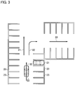
- FIG. 3 illustrates a travel scene for explaining an operation example of the parking assistance device according to the embodiment of the present invention
- FIG. 4 is a diagram for explaining the operation example of the parking assistance device according to the embodiment of the present invention.
- FIG. 5 illustrates a travel scene for explaining a different operation example of the parking assistance device according to the embodiment of the present invention
- FIG. 6 is a diagram for explaining the different operation example of the parking assistance device according to the embodiment of the present invention.
- FIG. 7 is a travel scene for explaining a further different operation example of the parking assistance device according to the embodiment of the present invention.
- FIG. 8A is a flowchart for explaining an operation example of the parking assistance device according to the embodiment of the present invention.
- FIG. 8B is a flowchart for explaining the operation example of the parking assistance device according to the embodiment of the present invention.
- FIG. 9 is a diagram for explaining a further different operation example of the parking assistance device according to the embodiment of the present invention.
- a parking assistance device is applied to a vehicle in which its driving mode can be switched between automated driving and manual driving, but the application is not limited to this example.
- the parking assistance device according to the present embodiment is also applicable to various mobile objects, such as, for example, industrial vehicles (for example, trucks), airplanes, aircraft, underwater mobile objects (for example, sea-bottom probes, submarines), machines with an inverted pendulum, and cleaning robots.
- automated driving in the present embodiment means, for example, the state where at least one of the actuators including the brakes, accelerator, and steering is being controlled without operation by the driver.
- the automated driving includes the state where at least one of the actuators is being controlled and the other actuators are being operated by the driver.
- Manual driving in the present embodiment means, for example, the state where the driver is performing necessary operation for traveling such as braking, acceleration, and steering.
- the parking assistance device includes a controller 1 , cameras 2 a to 2 d , a steering angle sensor 3 , a steering-wheel angle sensor 4 , a wheel speed sensor 6 , a spatial recognition sensor 7 , an input interface 8 , a display 9 , a vehicle control ECU 10 , and an actuator 11 .
- the cameras 2 a to 2 d each have an image capturing device, such as a charge-coupled device (CCD) or a complementary metal oxide semiconductor (CMOS) and capture images around the host vehicle.
- the camera 2 a is mounted at a front portion of the host vehicle to capture images ahead of the host vehicle.
- the camera 2 b is mounted at a rear portion of the host vehicle to capture images behind the host vehicle.
- the camera 2 c is mounted at a left side of the host vehicle to capture images on the left side of the host vehicle.
- the camera 2 d is mounted at a right side of the host vehicle to capture images on the right side of the host vehicle.
- Each camera is attached below the roof of the host vehicle.
- each camera Since each camera is located below the roof of the host vehicle, it is difficult to display an image actually captured from information on the host vehicle.
- the tires of the host vehicle are housed in the wheel wells, it is difficult to capture images of the outer circle surfaces of the tires of the host vehicle (side surfaces, assuming that the tire is a cylinder).
- it is difficult to capture images of the host vehicle and the tires of the host vehicle it is difficult to obtain actual images of the host vehicle and the tires. For this reason, instead of an actual image of the host vehicle, an icon of the host vehicle (an image imitating the host vehicle) described later is used.
- the steering angle sensor 3 detects the steering angle of the host vehicle when the host vehicle is operating to park into an empty parking space (or by the time when the host vehicle is parked into an empty parking space).
- the steering angle sensor 3 may directly detect the orientations of tires of the host vehicle or may detect the steering angle from the angle of the steering wheel of the host vehicle.
- the steering angle sensor 3 outputs the detected steering angle to the controller 1 . Note that the steering angle does not need to be detected all the time until parking operation is finished, the steering angle only needs to be calculated at timings set in advance.
- the steering-wheel angle sensor 4 detects the steering-wheel angle (the angle of steering operation) of the host vehicle and outputs the detected steering-wheel angle to the controller 1 .
- the wheel speed sensor 6 detects the speed of the host vehicle and outputs the detected speed to the controller 1 .
- the spatial recognition sensor 7 is a sensor for detecting objects around the host vehicle, which is, for example, a laser range finder.
- the laser range finder projects infrared laser light toward a target object and measures the distance to the target object using the intensity of the reflected light.
- the laser range finder obtains the measured distance as point cloud information and outputs the point cloud information to a sensor-information processing unit 104 .
- Objects around the host vehicle mean moving objects including other vehicles, motorbikes, bicycles, and pedestrians and stationary objects including parked vehicles. Note that the spatial recognition sensor 7 is not limited to a laser range finder.
- the spatial recognition sensor 7 only needs to detect the distance to a target object and the presence of the target object, and hence the spatial recognition sensor 7 may be, for example, a clearance sonar utilizing ultrasonic, a monocular camera, or a stereo camera having a pair of cameras.
- the input interface 8 is a device that receives input from the occupant of the host vehicle.
- the input interface 8 is, for example, a touch panel provided on the display 9 .
- the input interface 8 may be a joystick or an operation switch or may be a voice input device.
- the controller 1 is circuitry that processes data obtained from various sensors and is, for example, a general-purpose microcomputer including a central processing unit (CPU), memory, and an input-output unit.
- a computer program that causes the microcomputer to function as the controller 1 is installed in and executed by the microcomputer. This makes the microcomputer function as the controller 1 .
- description is made of an example in which the controller 1 is implemented by software, dedicated hardware for executing information processes described below, as a matter of course, may be used to configure the controller 1 .
- the controller 1 includes multiple information process circuits, which are a surrounding-image generation unit 101 , an image display circuit 102 , an icon storing unit 103 , the sensor-information processing unit 104 , a parking-assistance calculation unit 105 , and a turning determination unit 106 .
- the image display circuit 102 includes an assistance-image generation unit 1021 , a display-switching control unit 1022 , and an image composition unit 1023 .
- the surrounding-image generation unit 101 (surrounding-image generation circuit) sets a predetermined virtual eyepoint and picture plane based on images of surroundings of the host vehicle captured by the four cameras 2 a to 2 d and generates an image (downward view image) that looks as if the host vehicle is looked down from above (toward the vehicle). Since how to generate the downward view image is a known technique, detailed description thereof is omitted. Note that in the present embodiment, the image described above does not need to be a downward view image, but it may be any image (surrounding image) that shows the surroundings of the host vehicle, such as a bird's view image.
- the surrounding-image generation unit 101 may receive images captured by cameras provided in a parking lot or cameras mounted on another vehicle via wireless communication and generate a downward view image (surrounding image). Note that in the present embodiment, in the case where an image captured from above the host vehicle is used, it is not necessary to use an image imitating the host vehicle (a vehicle icon).
- the sensor-information processing unit 104 estimates a travel path along which the host vehicle is to travel, using information obtained from the spatial recognition sensor 7 .
- the sensor-information processing unit 104 estimates a parking area (parking spot) in the vicinities of the estimated travel path.
- the sensor-information processing unit 104 estimates the range in which the host vehicle can travel based on the estimated travel path and parking spots.
- the sensor-information processing unit 104 may detect parking spots using white lines on the ground.
- the turning determination unit 106 determines whether the host vehicle is turning, using the steering-wheel angle obtained from the steering-wheel angle sensor 4 .
- the turning determination unit 106 outputs the determination result to the display-switching control unit 1022 .
- the assistance-image generation unit 1021 generates assistance images for assisting parking.
- the assistance images may be stored in the icon storing unit 103 in advance.
- the assistance-image generation unit 1021 can read the assistance images from the icon storing unit 103 .
- the assistance-image generation unit 1021 outputs the generated assistance images to the display-switching control unit 1022 .
- the display-switching control unit 1022 determines whether to output an assistance image obtained from the assistance-image generation unit 1021 to the image composition unit 1023 , based on the determination result made by the turning determination unit 106 . For example, in the case where the steering-wheel angle is larger than or equal to ⁇ 180 degrees, the display-switching control unit 1022 outputs the assistance image to the image composition unit 1023 . Details will be described later.
- the image composition unit 1023 superimposes the icon (an image imitating the host vehicle) obtained from the icon storing unit 103 on the downward view image generated by surrounding-image generation unit 101 to generate a composite image.
- the image composition unit 1023 obtains an assistance image from the display-switching control unit 1022
- the image composition unit 1023 superimposes this assistance image on the downward view image.
- the image composition unit 1023 outputs the composed image to the display 9 .
- the parking-assistance calculation unit 105 calculates a control signal for the host vehicle based on information inputted to the input interface 8 , data obtained by the sensor-information processing unit 104 , the steering angle detected by the steering angle sensor 3 , and the speed detected by the wheel speed sensor 6 .
- the parking-assistance calculation unit 105 outputs the calculated control signal to the vehicle control ECU 10 .
- the vehicle control ECU 10 automatically controls driving of the actuator 11 on driving, braking, and steering the host vehicle, based on the control signal and the like obtained from the parking-assistance calculation unit 105 .
- the display 9 is a device for displaying various kinds of information for the occupant, which is, for example, a display for navigation provided in the passenger compartment.
- the parking-assistance calculation unit 105 includes a target-parking-spot setting unit 1051 , parking-start-position setting unit 1052 , self-position estimation unit 1053 , parking-trajectory generation unit 1054 , parking-trajectory tracking-control unit 1055 , and target-speed generation unit 1056 .
- the target-parking-spot setting unit 1051 sets the target parking position to a parking position that the occupant input to the input interface 8 .
- the target-parking-spot setting unit 1051 outputs the set target parking position to the parking-start-position setting unit 1052 and the parking-trajectory generation unit 1054 .
- the parking-start-position setting unit 1052 determines a parking method suitable for parking at the target parking position and sets a parking start position suitable for the determined parking method. Examples of the parking method include parallel parking and perpendicular parking.
- the parking-start-position setting unit 1052 outputs the set parking start position to the parking-trajectory generation unit 1054 .
- the self-position estimation unit 1053 estimates the current position of the host vehicle, based on detection data and the like of the wheel speed sensor 6 and steering angle sensor 3 .
- a dead reckoning approach in which the position and orientation of the host vehicle are estimated based on the relationship between the travel distance of the center of the rear wheel axle and the front-wheel steering angle.
- the dead reckoning approach is useful for the case of considering traveling in a limited section such as parking operation.
- the self-position estimation unit 1053 can also estimate the self-position based on the positional relationship of the host vehicle relative to detection data detected by the spatial recognition sensor 7 , the positional relationship of the host vehicle relative to white lines on the ground captured by the cameras 2 a to 2 d and object recognition results, or the like.
- the self-position estimation unit 1053 may estimate the absolute position of the host vehicle, in other words, the position of the host vehicle relative to a specified reference point, using a position detection sensor.
- the position detection sensor is a device mounted on the host vehicle for measuring the absolute position of the host vehicle using a global positioning system (GPS), odometry, or the like.
- GPS global positioning system
- the self-position estimation unit 1053 outputs the estimated self-position to the parking-trajectory tracking-control unit 1055 .
- the parking-trajectory generation unit 1054 generates a parking trajectory from the parking start position set by the parking-start-position setting unit 1052 to the target parking position.
- the parking-trajectory generation unit 1054 generates a parking trajectory, for example, such that the number of forward and backward movements and the amount of steering are minimized, so that the occupant does not feel discomfort.
- the parking-trajectory generation unit 1054 outputs the generated parking trajectory to the parking-trajectory tracking-control unit 1055 and the target-speed generation unit 1056 .
- the parking-trajectory tracking-control unit 1055 generates a control signal for performing automatic parking control along the parking trajectory, based on the parking trajectory generated by the parking-trajectory generation unit 1054 and the self-position estimated by the self-position estimation unit 1053 . For example, the parking-trajectory tracking-control unit 1055 generates a control signal related to the steering angle and the shift position. The parking-trajectory tracking-control unit 1055 outputs the generated control signal to the vehicle control ECU 10 .
- the target-speed generation unit 1056 generates a control signal for performing automatic parking control along the parking trajectory generated by the parking-trajectory generation unit 1054 .
- the target-speed generation unit 1056 generates a control signal related to the speed (the amount of acceleration and the amount of braking).
- the target-speed generation unit 1056 outputs the generated control signal to the vehicle control ECU 10 .
- the vehicle control ECU 10 controls the actuator 11 based on the control signals generated by the parking-trajectory tracking-control unit 1055 and the target-speed generation unit 1056 to achieve automatic parking control.
- Road markings 30 , 31 , 32 , and 33 illustrated in FIG. 3 are road markings provided on the ground.
- the road markings 30 , 31 , and 33 show that the vehicle is allowed to travel straight.
- the road marking 32 shows that the vehicle is allowed to turn right.
- Another vehicle 21 illustrated in FIG. 3 is a parked vehicle. Note that in the present embodiment, the time when the host vehicle 22 is traveling in the parking lot means the time when the host vehicle 22 is traveling on a road adjoining empty parking spaces.
- the time when the host vehicle 22 is parked in an empty parking space is the time when the host vehicle 22 is at a standstill in a parking space, which is different from the time when traveling in a parking lot.
- the time when the host vehicle 22 is traveling in a parking lot in the present embodiment may include the time when traveling on empty parking spaces.
- FIG. 4 illustrates a downward view image 20 which is a view of the host vehicle 22 looked down from above in the scene illustrated in FIG. 3 .
- the turning determination unit 106 determines whether the host vehicle 22 is turning. For example, when the steering-wheel angle is larger than or equal to ⁇ 180 degrees, the turning determination unit 106 determines that the host vehicle 22 is turning. When the steering-wheel angle is smaller than ⁇ 180 degrees, the turning determination unit 106 determines that the host vehicle 22 is not turning. Note that in the case where the host vehicle 22 is not turning in the present embodiment, the host vehicle 22 is traveling straight.
- the image composition unit 1023 displays assistance images 24 and 25 (first assistance images) at empty parking spaces 23 . Also, when the turning determination unit 106 determines that the state of the host vehicle 22 has changed from turning to traveling straight, the image composition unit 1023 displays the assistance images 24 and 25 (the first assistance image) at empty parking spaces 23 .
- the assistance images 24 and 25 are images indicating that the parking space is empty.
- the assistance image 25 shows that the parking space is empty and also that this place is a recommended parking space.
- the recommended parking space means, for example, a space that is easy to park in.
- the recommended parking space may be a space that requires a shorter time to park there or may be a space the parking trajectory to which is short.
- the recommended parking space may also be a space the parking trajectory to which includes no sharp turn, a space into which reverse parking is possible, or a space that is easy to exit from.
- the assistance image 24 only indicates that the parking space is empty.
- the assistance images 24 and 25 are displayed at the empty parking spaces 23 as described above while the host vehicle 22 is traveling straight, the occupant can easily understand that the empty parking spaces 23 are empty. This allows the occupant to take actions to park in a desired empty parking space. For example, in the case where automatic parking control is available as in the present embodiment, the occupant's touch on the assistance image 25 (recommended parking space) initiates automatic parking control to the target parking position.
- the host vehicle 22 has traveled forward a little from the scene illustrated in FIG. 3 .
- the host vehicle 22 is turning right and that the steering-wheel angle is larger than or equal to 180 degrees in the clockwise direction.
- the downward view image 20 corresponding to the scene illustrated in FIG. 5 is illustrated in FIG. 6 .
- the sensor-information processing unit 104 detects empty parking spaces 23 around the host vehicle 22 as illustrated in FIG. 6
- the turning determination unit 106 determines whether the host vehicle 22 is turning.
- the image composition unit 1023 does not display the assistance image 24 or assistance image 25 illustrated in FIG. 4 on the downward view image 20 .
- the image composition unit 1023 prohibits the assistance image 24 or the assistance image 25 from being displayed.
- the sensor-information processing unit 104 may erroneously detect the states of empty parking spaces 23 .
- the erroneous detection of the state of an empty parking space 23 means, for example, detecting a space that is not an empty parking space 23 , as an empty parking space.
- the motion of a camera positioned far from the turning center is faster than the motion of a camera positioned near the turning center.
- the accuracy of a camera positioned far from the turning center may be low.
- a camera positioned far from the turning center may erroneously detect the state of an empty parking space 23 .
- an object (including a parking space) nearer to the host vehicle 22 moves faster on an image, making it difficult to detect the object using an image.
- the sensor-information processing unit 104 may erroneously detect the state of an empty parking space 23 . This is also a reason of the prohibition.
- the image composition unit 1023 prohibits the assistance image 24 or the assistance image 25 from being displayed when the host vehicle 22 is turning.
- the positional deviation of the assistance images 24 and 25 may be large when they are displayed.
- the image composition unit 1023 displays the assistance images 24 and 25 at the empty parking spaces 23 , first the image composition unit 1023 recognizes the empty parking spaces 23 in the downward view image 20 . Next. the image composition unit 1023 displays the assistance images 24 and 25 at the recognized empty parking spaces 23 . If the host vehicle 22 moves when the image composition unit 1023 performs the processing above, the empty parking spaces 23 recognized by the image composition unit 1023 in the downward view image 20 also move.
- the image composition unit 1023 recognizes the empty parking spaces 23 , and at the next moment when the image composition unit 1023 is about to display the assistance images 24 and 25 at the recognized empty parking spaces 23 , the recognized empty parking spaces 23 move. In this way, a time lag occurs between the time when the image composition unit 1023 recognizes the empty parking spaces 23 and the time when the image composition unit 1023 displays the assistance images 24 and 25 at the recognized empty parking spaces 23 . This time lag may cause positional deviation between the positions of the empty parking spaces 23 and the positions of the assistance images 24 and 25 .
- the host vehicle 22 is turning, there is a case where the positional deviation in the display is large because the accuracy of a camera positioned far from the turning center is low.
- the image composition unit 1023 may display the assistance images 24 and 25 at appropriate positions.
- the road marking 31 and the road marking 32 illustrated in FIG. 5 may be erroneously detected as markings of parking spots.
- the image composition unit 1023 prohibits the assistance images 24 and 25 from being displayed at the empty parking spaces 23 . This prevents the image composition unit 1023 from providing wrong information to the occupant. Note that although in the example illustrated in FIG. 6 , description has been made of prohibiting the assistance images 24 and 25 from being displayed, the present invention is not limited to this operation. For example, when the host vehicle 22 is turning, the image composition unit 1023 may prohibit marking of parking spots 27 illustrated in FIG. 6 from being displayed.
- the scene illustrated in FIG. 7 is a scene in which the state of the host vehicle 22 has just changed from turning to traveling straight.
- the image composition unit 1023 prohibits the assistance images 24 and 25 from being displayed at an empty parking space 28 positioned behind the host vehicle 22 .
- the empty parking space 28 can be a result of erroneous detection because the empty parking space 28 is an empty parking space detected when the host vehicle 22 was turning.
- the image composition unit 1023 displays the assistance images 24 and 25 .
- the empty parking spaces may include the empty parking space that meets parking conditions inputted by the occupant in advance.
- an empty parking space that meets parking conditions inputted by the occupant in advance is simply referred to as a parking target.
- the types of empty parking space can be categorized depending on whether a parking space meets a specified condition. For example, if a parking space meets the condition that it is empty, the parking space is regarded as an empty parking space. If a parking space meets the condition for being recommended, the parking space is regarded as a recommended parking space.
- the parking space is regarded as a parking target.
- the image composition unit 1023 displays an assistance image at the parking target, and the assistance image displayed in this case should preferably be an assistance image different from the assistance image 24 or the assistance image 25 .
- the assistance image displayed at a parking target may be the assistance image 24 or the assistance image 25 .
- the image composition unit 1023 prohibits the assistance images 24 and 25 from being displayed at empty parking spaces when the host vehicle 22 is turning
- the image composition unit 1023 may prohibit the assistance images 24 and 25 from being displayed depending on the type of empty parking space.
- the image composition unit 1023 may display the assistance images 24 and 25 depending on the type of empty parking space. For example, in the case where a parking target and a merely empty parking space are detected when the host vehicle 22 is turning, the image composition unit 1023 may prohibit an assistance image from being displayed at the parking target and may display an assistance image 24 at the merely empty parking space.
- the image composition unit 1023 Since the parking target is a parking space preferred to the occupant, the image composition unit 1023 only prohibits an assistance image from being displayed at the parking target, so that it is possible to prevent wrong information from being provided to the occupant. In the case where a parking target, a recommended parking space, and a merely empty parking space are detected when the host vehicle 22 is turning, the image composition unit 1023 may only prohibit an assistance image from being displayed at the parking target and may display the assistance image 25 at the recommended parking space and display the assistance image 24 at the merely empty parking space.
- the sensor-information processing unit 104 searches for empty parking spaces based on information obtained from the spatial recognition sensor 7 .
- the process proceeds to step S 103 , at which if the sensor-information processing unit 104 detects an empty parking space around the host vehicle 22 (Yes at step S 103 ), the process proceeds to step S 105 .
- step S 103 if the sensor-information processing unit 104 does not detect an empty parking space around the host vehicle 22 (No at step S 103 ), the process keeps waiting.
- the turning determination unit 106 determines whether the host vehicle 22 is turning. For example, in the case where the steering-wheel angle is larger than or equal to ⁇ 180 degrees, the turning determination unit 106 determines that the host vehicle 22 is turning. If the turning determination unit 106 determines that the host vehicle 22 is turning (Yes at step S 105 ), the process proceeds to step S 107 , where the image composition unit 1023 does not display the assistance image 24 or 25 at empty parking spaces 23 . The reason is that the sensor-information processing unit 104 may erroneously detect the states of empty parking spaces 23 when the host vehicle 22 is turning.
- step S 109 the image composition unit 1023 displays the assistance images 24 and 25 at empty parking spaces 23 as illustrated in FIG. 4 . This makes it easy for the occupant to understand that the empty parking spaces 23 are empty.
- step S 115 if the occupant selects a desired empty parking space via the input interface 8 (Yes at step S 115 ), the process proceeds to step S 117 . On the other hand, if there is no input from the occupant, the process returns to step S 103 .
- the target-parking-spot setting unit 1051 sets the target parking position to the empty parking space selected by the occupant.
- the parking-start-position setting unit 1052 determines the parking method and sets a parking start position suitable for the determined parking method. Note that in this flowchart, description is made assuming that the parking method is reverse parking.
- the process proceeds to step S 119 , where the parking-trajectory generation unit 1054 generates a parking trajectory from the parking start position set at step S 117 to the target parking position.
- the process proceeds to step S 121 , where the vehicle control ECU 10 starts the automatic parking control.
- step S 123 the self-position estimation unit 1053 determines whether the host vehicle 22 has reached the position at which the shift position is to be switched. If the host vehicle 22 has reached the position at which the shift position is to be switched (Yes at step S 123 ), the process proceeds to step S 125 , where the vehicle control ECU 10 performs shift switching control. After that, the vehicle control ECU 10 continues the automatic parking control, and the process proceeds to step S 127 . On the other hand, if the host vehicle 22 has not reached the position at which the shift position is to be switched (No at step S 123 ), the process keeps waiting. At step S 127 , the self-position estimation unit 1053 determines whether the host vehicle 22 has reached the target parking position. If the host vehicle 22 has reached the target parking position (Yes at step S 127 ), the process proceeds to step S 129 , where the vehicle control ECU 10 performs control such as changing the shift position to the parking position, and then the automatic parking control ends.
- the parking assistance device provides the following operational advantages.
- the turning determination unit 106 determines whether the host vehicle 22 is turning. In the case where the turning determination unit 106 determines that the host vehicle 22 is turning, the image composition unit 1023 prohibits the assistance images 24 and 25 from being displayed at empty parking spaces 23 in the downward view image 20 as illustrated in FIG. 6 . This prevents the parking assistance device from providing wrong information to the occupant even if the sensor-information processing unit 104 erroneously detects the states of empty parking spaces 23 .
- the assistance images 24 and 25 are displayed at the positions of empty parking spaces. Since it is possible to provide the assistance images to the occupant in the state where it is unlikely to provide wrong information to the occupant, the occupant can understand the states of the parking spaces accurately.
- the image composition unit 1023 prohibits the assistance images 24 and 25 from being displayed at the empty parking space 28 which is positioned behind the host vehicle 22 just after the state change. This prevents the parking assistance device from providing wrong information to the occupant even when the sensor-information processing unit 104 erroneously detects the state of the empty parking space 28 .
- the turning determination unit 106 determines that the host vehicle 22 is turning. Since the image composition unit 1023 prohibits the assistance images 24 and 25 from being displayed in the case where the turning angle of the host vehicle 22 is larger than or equal to a specified value, it is possible to prevent the parking assistance device from providing wrong information to the occupant.
- the turning angle of the host vehicle 22 may be determined from the steering-wheel angle or the steering angle.
- the image composition unit 1023 may display, for example, an assistance image 26 (second assistance image) at a certain position different from the position of the empty parking space 23 , as illustrated in FIG. 9 .
- the assistance image 26 is an image for indicating that an empty parking space 23 has been detected around the host vehicle 22 . Because the assistance image 26 is not an image indicating an empty parking space 23 itself, the assistance image 26 is displayed at a position different from that of the empty parking space 23 . Displaying the assistance image 26 at a position different from that of the empty parking space 23 enables the occupant to easily understand, by seeing the assistance image 26 , that there is an empty parking space 23 .
- the image composition unit 1023 deletes the assistance image 26 .
- the image composition unit 1023 displays the assistance images 24 and 25 at empty parking spaces.
- the assistance image 26 is not necessary.
- the image composition unit 1023 deletes the assistance image 26 .
- the assistance image 26 illustrated in FIG. 9 is represented in a quadrangle shape, and the assistance images 24 and 25 illustrated in FIG. 4 are each represented in a round shape, the shapes are not limited to these examples.
- the assistance image 26 and the assistance images 24 and 25 may have any shape that can be distinguished one from the others.
- the image composition unit 1023 may make the color of the assistance image 26 fainter (for example, gray), instead of deleting the assistance image 26 .
- the turning determination unit 106 may determine whether the host vehicle 22 is turning, based on to the steering-wheel angle and the speed. For example, the turning determination unit 106 may determine that the host vehicle 22 is turning in the case where the steering-wheel angle is larger than or equal to ⁇ 180 degrees and where the speed of the host vehicle 22 is larger than or equal to 3 km/h. In this way, the image composition unit 1023 prohibiting the assistance images 24 and 25 from being displayed in the case where the steering-wheel angle of the host vehicle 22 is larger than or equal to a specified value and where the speed of the host vehicle 22 is larger than or equal to a specified value (second specified value) prevents the parking assistance device from providing wrong information to the occupant.
- a specified value second specified value
- the turning determination unit 106 may determine that the host vehicle 22 is not turning. In the case where the steering-wheel angle is smaller than ⁇ 180 degrees, the turning determination unit 106 may determines that the host vehicle 22 is not turning, regardless of the speed of the host vehicle 22 .
- the numerical values of ⁇ 180 degrees and 3 km/h are mere examples. Thus, the present invention is not limited to these values, but the values can be changed as appropriate.
- the driving mode at the time when the sensor-information processing unit 104 searches for an empty parking space may be either manual driving by the occupant or automated driving.
Landscapes
- Engineering & Computer Science (AREA)
- Mechanical Engineering (AREA)
- Transportation (AREA)
- Automation & Control Theory (AREA)
- Physics & Mathematics (AREA)
- Multimedia (AREA)
- General Physics & Mathematics (AREA)
- Chemical & Material Sciences (AREA)
- Combustion & Propulsion (AREA)
- Mathematical Physics (AREA)
- Theoretical Computer Science (AREA)
- Human Computer Interaction (AREA)
- Traffic Control Systems (AREA)
- Control Of Driving Devices And Active Controlling Of Vehicle (AREA)
- Instrument Panels (AREA)
Applications Claiming Priority (1)
| Application Number | Priority Date | Filing Date | Title |
|---|---|---|---|
| PCT/JP2017/025007 WO2019008760A1 (fr) | 2017-07-07 | 2017-07-07 | Procédé d'aide au stationnement et dispositif d'aide au stationnement |
Publications (2)
| Publication Number | Publication Date |
|---|---|
| US20200369204A1 US20200369204A1 (en) | 2020-11-26 |
| US10926701B2 true US10926701B2 (en) | 2021-02-23 |
Family
ID=64950740
Family Applications (1)
| Application Number | Title | Priority Date | Filing Date |
|---|---|---|---|
| US16/625,490 Active US10926701B2 (en) | 2017-07-07 | 2017-07-07 | Parking assistance method and parking assistance device |
Country Status (10)
| Country | Link |
|---|---|
| US (1) | US10926701B2 (fr) |
| EP (2) | EP3650284B1 (fr) |
| JP (1) | JP6801785B2 (fr) |
| KR (1) | KR102145747B1 (fr) |
| CN (1) | CN110730735B (fr) |
| BR (1) | BR112020000272B1 (fr) |
| CA (1) | CA3069117C (fr) |
| MX (1) | MX2019015110A (fr) |
| RU (1) | RU2729330C1 (fr) |
| WO (1) | WO2019008760A1 (fr) |
Cited By (2)
| Publication number | Priority date | Publication date | Assignee | Title |
|---|---|---|---|---|
| US20200398742A1 (en) * | 2018-02-20 | 2020-12-24 | Audi Ag | Method for operating a driver assistance unit of a motor vehicle using a navigation target specification device, control unit, navigation target specification device, and motor vehicle |
| US11180135B2 (en) * | 2018-01-31 | 2021-11-23 | Lg Electronics Inc. | Autonomous parking system and vehicle |
Families Citing this family (4)
| Publication number | Priority date | Publication date | Assignee | Title |
|---|---|---|---|---|
| WO2019181260A1 (fr) * | 2018-03-22 | 2019-09-26 | 日立オートモティブシステムズ株式会社 | Dispositif d'aide au stationnement |
| JP7218172B2 (ja) * | 2018-12-25 | 2023-02-06 | フォルシアクラリオン・エレクトロニクス株式会社 | 車載処理装置、及び車載処理装置の制御方法 |
| KR20210030751A (ko) * | 2019-09-10 | 2021-03-18 | 현대자동차주식회사 | 주차공간의 탑뷰 이미지 제공 장치 및 그 방법 |
| JP2021180382A (ja) * | 2020-05-12 | 2021-11-18 | フォルシアクラリオン・エレクトロニクス株式会社 | 画像処理装置及び画像処理方法 |
Citations (9)
| Publication number | Priority date | Publication date | Assignee | Title |
|---|---|---|---|---|
| US20070146165A1 (en) | 2005-12-27 | 2007-06-28 | Aisin Seiki Kabushiki Kaisha | Parking assistance system |
| JP2008096362A (ja) | 2006-10-13 | 2008-04-24 | Denso Corp | 車載用ナビゲーション装置 |
| JP2012001144A (ja) | 2010-06-18 | 2012-01-05 | Aisin Seiki Co Ltd | 駐車支援装置 |
| US20130144492A1 (en) * | 2010-06-09 | 2013-06-06 | Teruhisa Takano | Parking mode selection apparatus and method |
| JP2014125195A (ja) | 2012-12-27 | 2014-07-07 | Nissan Motor Co Ltd | 駐車支援装置、駐車支援システム及び駐車支援方法 |
| JP2017024596A (ja) | 2015-07-23 | 2017-02-02 | Kyb株式会社 | 駐車誘導装置 |
| CA3002638A1 (fr) | 2015-10-22 | 2017-04-27 | Nissan Motor Co., Ltd. | Dispositif d'aide au stationnement et procede d'aide au stationnement |
| WO2017068701A1 (fr) | 2015-10-22 | 2017-04-27 | 日産自動車株式会社 | Procédé et dispositif de détection de places de stationnement |
| US20190001968A1 (en) * | 2017-07-03 | 2019-01-03 | Toyota Jidosha Kabushiki Kaisha | Vehicle surrounding display apparatus |
Family Cites Families (9)
| Publication number | Priority date | Publication date | Assignee | Title |
|---|---|---|---|---|
| JP3879958B2 (ja) | 1999-01-26 | 2007-02-14 | マツダ株式会社 | 車両の周囲情報報知装置 |
| JP3584194B2 (ja) | 2000-02-22 | 2004-11-04 | 株式会社ホンダエレシス | 白線検出方法および白線検出装置 |
| JP2003219411A (ja) | 2002-01-17 | 2003-07-31 | Clarion Co Ltd | 車両周囲監視方法および車両周囲監視装置 |
| JP4665721B2 (ja) | 2005-11-04 | 2011-04-06 | 株式会社デンソー | 駐車支援システム |
| US8890716B2 (en) * | 2010-06-11 | 2014-11-18 | Nissan Motor Co., Ltd. | Parking assist apparatus and method |
| KR101482171B1 (ko) * | 2013-09-05 | 2015-01-13 | 현대모비스(주) | 어라운드뷰 정차모드 제어방법 |
| CN107089227B (zh) * | 2013-10-04 | 2019-11-19 | 本田技研工业株式会社 | 停车辅助装置 |
| JP6523018B2 (ja) * | 2015-03-31 | 2019-05-29 | 株式会社デンソーテン | 駐車支援装置、及び駐車支援システム |
| EP3367362B1 (fr) * | 2015-10-22 | 2020-08-19 | Nissan Motor Co., Ltd. | Procédé d'aide au stationnement et dispositif d'aide au stationnement |
-
2017
- 2017-07-07 CA CA3069117A patent/CA3069117C/fr active Active
- 2017-07-07 EP EP17916473.6A patent/EP3650284B1/fr active Active
- 2017-07-07 WO PCT/JP2017/025007 patent/WO2019008760A1/fr unknown
- 2017-07-07 CN CN201780091854.7A patent/CN110730735B/zh active Active
- 2017-07-07 EP EP21157808.3A patent/EP3842294B1/fr active Active
- 2017-07-07 KR KR1020207003268A patent/KR102145747B1/ko active IP Right Grant
- 2017-07-07 MX MX2019015110A patent/MX2019015110A/es unknown
- 2017-07-07 RU RU2020105657A patent/RU2729330C1/ru active
- 2017-07-07 BR BR112020000272-0A patent/BR112020000272B1/pt active IP Right Grant
- 2017-07-07 JP JP2019528318A patent/JP6801785B2/ja active Active
- 2017-07-07 US US16/625,490 patent/US10926701B2/en active Active
Patent Citations (12)
| Publication number | Priority date | Publication date | Assignee | Title |
|---|---|---|---|---|
| US20070146165A1 (en) | 2005-12-27 | 2007-06-28 | Aisin Seiki Kabushiki Kaisha | Parking assistance system |
| JP2007176244A (ja) | 2005-12-27 | 2007-07-12 | Aisin Seiki Co Ltd | 駐車支援装置 |
| JP2008096362A (ja) | 2006-10-13 | 2008-04-24 | Denso Corp | 車載用ナビゲーション装置 |
| US20130144492A1 (en) * | 2010-06-09 | 2013-06-06 | Teruhisa Takano | Parking mode selection apparatus and method |
| JP2012001144A (ja) | 2010-06-18 | 2012-01-05 | Aisin Seiki Co Ltd | 駐車支援装置 |
| US20130060421A1 (en) * | 2010-06-18 | 2013-03-07 | Aisin Seiki Kabushiki Kaisha | Parking assistance apparatus |
| JP2014125195A (ja) | 2012-12-27 | 2014-07-07 | Nissan Motor Co Ltd | 駐車支援装置、駐車支援システム及び駐車支援方法 |
| JP2017024596A (ja) | 2015-07-23 | 2017-02-02 | Kyb株式会社 | 駐車誘導装置 |
| CA3002638A1 (fr) | 2015-10-22 | 2017-04-27 | Nissan Motor Co., Ltd. | Dispositif d'aide au stationnement et procede d'aide au stationnement |
| WO2017068701A1 (fr) | 2015-10-22 | 2017-04-27 | 日産自動車株式会社 | Procédé et dispositif de détection de places de stationnement |
| US10163016B2 (en) | 2015-10-22 | 2018-12-25 | Nissan Motor Co., Ltd. | Parking space detection method and device |
| US20190001968A1 (en) * | 2017-07-03 | 2019-01-03 | Toyota Jidosha Kabushiki Kaisha | Vehicle surrounding display apparatus |
Cited By (3)
| Publication number | Priority date | Publication date | Assignee | Title |
|---|---|---|---|---|
| US11180135B2 (en) * | 2018-01-31 | 2021-11-23 | Lg Electronics Inc. | Autonomous parking system and vehicle |
| US20200398742A1 (en) * | 2018-02-20 | 2020-12-24 | Audi Ag | Method for operating a driver assistance unit of a motor vehicle using a navigation target specification device, control unit, navigation target specification device, and motor vehicle |
| US11691672B2 (en) * | 2018-02-20 | 2023-07-04 | Audi Ag | Method for operating a driver assistance unit of a motor vehicle using a navigation target specification device, control unit, navigation target specification device, and motor vehicle |
Also Published As
| Publication number | Publication date |
|---|---|
| US20200369204A1 (en) | 2020-11-26 |
| CA3069117C (fr) | 2020-08-18 |
| EP3650284A4 (fr) | 2020-05-27 |
| WO2019008760A1 (fr) | 2019-01-10 |
| KR20200024913A (ko) | 2020-03-09 |
| EP3650284B1 (fr) | 2021-04-28 |
| KR102145747B1 (ko) | 2020-08-20 |
| BR112020000272B1 (pt) | 2023-03-21 |
| CN110730735B (zh) | 2020-09-22 |
| EP3842294A1 (fr) | 2021-06-30 |
| JPWO2019008760A1 (ja) | 2020-04-09 |
| EP3650284A1 (fr) | 2020-05-13 |
| CA3069117A1 (fr) | 2019-01-10 |
| EP3842294B1 (fr) | 2022-06-29 |
| BR112020000272A2 (pt) | 2020-07-14 |
| MX2019015110A (es) | 2020-02-05 |
| CN110730735A (zh) | 2020-01-24 |
| JP6801785B2 (ja) | 2020-12-16 |
| RU2729330C1 (ru) | 2020-08-06 |
Similar Documents
| Publication | Publication Date | Title |
|---|---|---|
| US10926701B2 (en) | Parking assistance method and parking assistance device | |
| US10789845B2 (en) | Parking assistance method and parking assistance device | |
| EP3290301B1 (fr) | Dispositif d'assistance au parcage | |
| US9896098B2 (en) | Vehicle travel control device | |
| EP3650315B1 (fr) | Procédé d'aide au stationnement et dispositif d'aide au stationnement | |
| JP2020056733A (ja) | 車両制御装置 | |
| JP2024054292A (ja) | 駐車支援方法及び駐車支援装置 | |
| JP7059525B2 (ja) | 駐車支援方法及び駐車支援装置 | |
| US20240157965A1 (en) | Driving assistance device and driving assistance method |
Legal Events
| Date | Code | Title | Description |
|---|---|---|---|
| FEPP | Fee payment procedure |
Free format text: ENTITY STATUS SET TO UNDISCOUNTED (ORIGINAL EVENT CODE: BIG.); ENTITY STATUS OF PATENT OWNER: LARGE ENTITY |
|
| AS | Assignment |
Owner name: NISSAN MOTOR CO., LTD., JAPAN Free format text: ASSIGNMENT OF ASSIGNORS INTEREST;ASSIGNORS:SUZUKI, YASUHIRO;SATO, KO;TANAKA, DAISUKE;AND OTHERS;REEL/FRAME:051366/0913 Effective date: 20191028 |
|
| STPP | Information on status: patent application and granting procedure in general |
Free format text: RESPONSE TO NON-FINAL OFFICE ACTION ENTERED AND FORWARDED TO EXAMINER |
|
| STCF | Information on status: patent grant |
Free format text: PATENTED CASE |