US10856431B2 - Carrier assembly for carrying an electronics housing - Google Patents
Carrier assembly for carrying an electronics housing Download PDFInfo
- Publication number
- US10856431B2 US10856431B2 US16/077,488 US201716077488A US10856431B2 US 10856431 B2 US10856431 B2 US 10856431B2 US 201716077488 A US201716077488 A US 201716077488A US 10856431 B2 US10856431 B2 US 10856431B2
- Authority
- US
- United States
- Prior art keywords
- carrier
- base
- locking element
- electronics housing
- carrier assembly
- Prior art date
- Legal status (The legal status is an assumption and is not a legal conclusion. Google has not performed a legal analysis and makes no representation as to the accuracy of the status listed.)
- Expired - Fee Related, expires
Links
- 230000036316 preload Effects 0.000 claims description 2
- 230000004907 flux Effects 0.000 description 5
- 238000003780 insertion Methods 0.000 description 5
- 230000037431 insertion Effects 0.000 description 5
- 239000004020 conductor Substances 0.000 description 4
- 229910000639 Spring steel Inorganic materials 0.000 description 3
- 238000011156 evaluation Methods 0.000 description 3
- 230000008901 benefit Effects 0.000 description 2
- 238000010616 electrical installation Methods 0.000 description 2
- 238000009434 installation Methods 0.000 description 2
- 239000002184 metal Substances 0.000 description 2
- 230000000712 assembly Effects 0.000 description 1
- 238000000429 assembly Methods 0.000 description 1
- 238000005315 distribution function Methods 0.000 description 1
- 238000012986 modification Methods 0.000 description 1
- 230000004048 modification Effects 0.000 description 1
Images


Classifications
-
- H—ELECTRICITY
- H05—ELECTRIC TECHNIQUES NOT OTHERWISE PROVIDED FOR
- H05K—PRINTED CIRCUITS; CASINGS OR CONSTRUCTIONAL DETAILS OF ELECTRIC APPARATUS; MANUFACTURE OF ASSEMBLAGES OF ELECTRICAL COMPONENTS
- H05K7/00—Constructional details common to different types of electric apparatus
- H05K7/14—Mounting supporting structure in casing or on frame or rack
- H05K7/1401—Mounting supporting structure in casing or on frame or rack comprising clamping or extracting means
-
- H—ELECTRICITY
- H05—ELECTRIC TECHNIQUES NOT OTHERWISE PROVIDED FOR
- H05K—PRINTED CIRCUITS; CASINGS OR CONSTRUCTIONAL DETAILS OF ELECTRIC APPARATUS; MANUFACTURE OF ASSEMBLAGES OF ELECTRICAL COMPONENTS
- H05K7/00—Constructional details common to different types of electric apparatus
- H05K7/14—Mounting supporting structure in casing or on frame or rack
- H05K7/1462—Mounting supporting structure in casing or on frame or rack for programmable logic controllers [PLC] for automation or industrial process control
- H05K7/1468—Mechanical features of input/output (I/O) modules
-
- F—MECHANICAL ENGINEERING; LIGHTING; HEATING; WEAPONS; BLASTING
- F16—ENGINEERING ELEMENTS AND UNITS; GENERAL MEASURES FOR PRODUCING AND MAINTAINING EFFECTIVE FUNCTIONING OF MACHINES OR INSTALLATIONS; THERMAL INSULATION IN GENERAL
- F16B—DEVICES FOR FASTENING OR SECURING CONSTRUCTIONAL ELEMENTS OR MACHINE PARTS TOGETHER, e.g. NAILS, BOLTS, CIRCLIPS, CLAMPS, CLIPS OR WEDGES; JOINTS OR JOINTING
- F16B2/00—Friction-grip releasable fastenings
- F16B2/20—Clips, i.e. with gripping action effected solely by the inherent resistance to deformation of the material of the fastening
- F16B2/22—Clips, i.e. with gripping action effected solely by the inherent resistance to deformation of the material of the fastening of resilient material, e.g. rubbery material
-
- H—ELECTRICITY
- H05—ELECTRIC TECHNIQUES NOT OTHERWISE PROVIDED FOR
- H05K—PRINTED CIRCUITS; CASINGS OR CONSTRUCTIONAL DETAILS OF ELECTRIC APPARATUS; MANUFACTURE OF ASSEMBLAGES OF ELECTRICAL COMPONENTS
- H05K7/00—Constructional details common to different types of electric apparatus
- H05K7/14—Mounting supporting structure in casing or on frame or rack
- H05K7/1462—Mounting supporting structure in casing or on frame or rack for programmable logic controllers [PLC] for automation or industrial process control
- H05K7/1474—Mounting of modules, e.g. on a base or rail or wall
Definitions
- the invention relates to a carrier assembly for carrying an electronics housing.
- a carrier assembly of this kind is used for example for carrying an electronics housing that may comprise electronics.
- Electrical conductors for example may be intended to be connected to the electronics housing in order to provide an electrical power supply to the electronics enclosed by the electronics housing, to feed sensor signals to the electronics, or to exchange other data signals with the electronics.
- the electronics housing may be intended to be fixed on a DIN rail by means of the carrier assembly, the DIN rail being designed to carry a plurality of modular units that can be put side-by-side on the DIN rail, such that it is possible, using modular electronics housings, series terminals or other devices, to provide an installation that can take on for example control, evaluation or other functions.
- the carrier assembly comprises a base and a carrier element that can be locked to the base.
- the electronics housing can be put on a slot of the carrier assembly and, when put on, is connected to the carrier assembly and held thereby on the carrier assembly.
- DE 20 27 157 A1 discloses a carrier assembly that can be put on a DIN rail.
- a housing of an electrical installation device can be connected to the carrier assembly.
- a housing comprises a latch spring by means of which the housing can be fixed on a mounting frame.
- DE 101 19 457 C1 describes a carrier that can be arranged on a DIN rail and forms a slot for latched connection of a housing to the carrier.
- EP 0 909 122 B1 discloses an electronic device to be put on a DIN rail.
- the electronic device comprises a housing that consists of a lower housing part that can be releasably connected to the DIN rail, and an upper housing part that can be releasably connected to the lower housing part.
- U.S. Pat. No. 6,840,819 B2 describes a carrier assembly that forms a slot on which an electronics housing is put.
- the carrier assembly can be arranged on a DIN rail in order to thus hold the electronics housing on the DIN rail.
- the present invention provides a carrier assembly for carrying an electronics housing, comprising: a base; a carrier element configured to be locked to the base; a slot configured to receive the electronics housing; and a locking element that is adjustably arranged on the carrier element, configured to lock the base to the carrier element when in a locked position, and is blocked in the locked position when the electronics housing is in the slot such that the locking element cannot be moved out of the locked position.
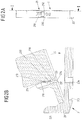
- FIG. 1 is a perspective view of a carrier assembly on which an electronics housing can be put;
- FIG. 2A is an end view of the carrier assembly when a carrier element is being put onto a base of the carrier assembly;
- FIG. 2B is a sectional view along the line I-I according to FIG. 2A ;
- FIG. 3A is an end view of the carrier assembly when an electronics housing is being put on
- FIG. 3B is a sectional view along the line II-II according to FIG. 3A ;
- FIG. 3C is a perspective view of the module
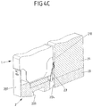
- FIG. 4A is an end view of the carrier assembly when the electronics housing has been put on
- FIG. 4B is a sectional view along the line according to FIG. 4A ;
- FIG. 4C is a perspective view of the module
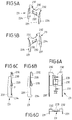
- FIG. 5A, 5B are views of a locking element for locking the carrier element to the base
- FIG. 6A is a front view of the locking element
- FIG. 6B is a sectional view along the line IV-IV according to FIG. 6A ;
- FIG. 6C is a side view of the locking element
- FIG. 6D is a plan view of the locking element.
- the carrier assembly comprises a locking element that is adjustably arranged on the carrier element and that locks the base to the carrier element when in a locked position and is blocked in the locked position, when an electronics housing is put on the slot, such that the locking element cannot be moved out of the locked position.
- the locking element establishes rigid locking between the carrier element and the base, which locking may be designed so as to be able to rigidly and reliably carry even large electronics housings.
- the locking element locks the base to the carrier element.
- the locking element can be moved between an unlocked position and a locked position, and is blocked in the locked position when an electronics housing is put on the slot formed by the carrier assembly.
- the locking element Since the locking element is blocked in the locked position thereof when an electronics housing is put on the slot of the carrier assembly, the locking between the base and the carrier element cannot be released when an electronics housing is located on the carrier assembly.
- the base When an electronics housing is put on, the base is thus rigidly and reliably connected to the carrier element. Only after the electronics housing has been removed can the locking between the base and the carrier element be released, such that the carrier element can be separated from the base.
- a two-part carrier assembly comprising a base and a carrier element that are to be releasably interconnected, it is possible to interconnect different bases and carrier elements in a modular manner.
- a uniform base may be provided for fixing the carrier assembly on a DIN rail.
- the base can be connected to different carrier elements that allow different electronics housings to be put onto the carrier assembly.
- the locking element locks the carrier element to the base when an electronics housing is put on the carrier assembly.
- an electronics housing is put on the carrier assembly, a rigid connection is thus created between the electronics housing, the carrier element and the base, in that the electronics housing is latched in the slot for example and the carrier element is locked to the base.
- the locking element is preferably designed so as to adjust itself from the unlocked position and into the locked position when the electronics housing is put on the slot. If the electronics housing is put on the slot, the electronics housing acts on the locking element and adjusts the locking element from the unlocked position and into the locked position, such that the locking between the carrier element and the base is established automatically when the electronics housing is put on. If the electronics housing is inserted into the slot, the locking element is held in the locked position and thus blocked in the locked position, such that the locking between the carrier element and the base cannot be released.
- the locking element is spring pre-loaded, relative to the carrier element, towards the unlocked position. The transfer of the locking element into the locked position thus takes place counter to the spring pre-loading. If the electronics housing is then released from the carrier assembly again, the locking element returns automatically into the unlocked position, due to spring pre-loading, such that the locking is automatically released when the electronics housing is removed and the carrier element can thus be released from the base.
- the locking element is pivotally held on the carrier element. In order to transfer the locking element between the unlocked position and the locked position, the locking element can thus be pivoted relative to the carrier element.
- the locking element may for example also be slidably arranged on the carrier element and be moved between the unlocked position and the locked position by means of sliding.
- the locking element may for example comprise a fastening element at a first end, which fastening element may be hook-shaped for example.
- the locking element can for example be suspended in an associated fastening means on the carrier element by means of the fastening element, such that the locking element is pivotally held on the carrier element.
- the locking element At a second end remote from the first end the locking element comprises an element that, in contrast to the first end, is interlocking and is intended for engagement with an associated latching element of the base.
- the interlocking element establishes the locking between the carrier element and the base in that the interlocking element, which can be formed in the manner of an undercut, engages behind an associated latching element of the base for the purpose of locking, and thus fixes the carrier element on the base in an interlocking manner.
- the flux of force extends between the fastening element on the first end of the locking element, and the interlocking element on the second end of the locking element. This flux of force introduces forces from the carrier element into the base, and via this for example into a DIN rail on which the base is arranged.
- the locking element comprises a foundation that extends along an extension plane, and at least one leg that extends on the foundation and protrudes from the foundation transversely to the extension plane, and on which the at least one interlocking element for engaging in an associated latching element of the base is arranged.
- the at least one fastening element for example, is arranged on the foundation, while the at least one leg carries the at least one interlocking element. Since the leg or legs protrude(s) transversely from the foundation, the strength of the locking element, which element may for example be manufactured as a sheet metal part from spring steel, is structurally reinforced.
- a spring leg may be arranged on the locking element, such that the spring leg protrudes from the foundation and comes into contact, in a pre-loading manner, with the carrier element when the locking element is transferred into the locked position.
- Said spring leg can provide spring pre-loading that pre-loads the locking element towards the unlocked position.
- two fastening elements transversely offset from one another, and two legs transversely offset from one another, each having an interlocking element arranged thereon, may be formed on the foundation.
- the legs extend for example laterally along the foundation and protrude from the foundation transversely to the extension plane.
- An interlocking element is formed on each leg.
- the locking element is for example integral, and is produced from a spring steel for example.
- the locking element passes through a first opening of the carrier element for example, and engages in a second opening of the base.
- the locking element for example rests in the first opening of the carrier element and is adjustable in said opening.
- the locking element engages with the second opening of the base and establishes an interlocking connection between the carrier element and the base when transferred into the locked position.
- a plurality of locking devices may be provided.
- at least one further locking device is preferably provided in addition to the locking element, which locking device connects the carrier element to the base at another point.
- the carrier element can thus be intended to be locked to the base at two mutually offset points (with respect to a longitudinal extension direction of the carrier element and of the base, transversely to an insertion direction in which the electronics housing is to be inserted into the slot, and transversely to a longitudinal direction of a DIN rail on which the base is to be put), it also being conceivable and possible in principle to provide locking at more than two, for example at three, points.
- An advantageous module comprises a carrier assembly according to the type described above, and an electronics housing that can be inserted into the slot formed by the carrier assembly. If the electronics housing is put on the carrier assembly, the locking element creates a rigid connection between the base and the carrier element, such that the electronics housing can be held on the base in a rigid, reliable and resilient manner by means of the carrier element.
- FIG. 1 is a view of a carrier assembly 2 that comprises a base 20 and a carrier element 21 put thereon and that can be put on a DIN rail 3 by means of a fastening point 200 on the base 20 and also forms a slot 22 for receiving an electronics housing 1 .
- a carrier assembly 2 of this kind is used for arranging an electronics housing 1 on a DIN rail 3 .
- a plurality of carrier assemblies 2 comprising electronics housings 1 can be inserted on the DIN rail 3 in a modular manner, such that an electrical installation can be created on the DIN rail 3 , optionally in conjunction with other components such as series terminals or the like, which installation can take on for example control, evaluation or distribution functions or the like.
- the carrier assembly 2 comprising the base 20 and the carrier element 21 is formed in two parts.
- the base 20 and the carrier element 21 each also comprise a guide element 201 , 210 which together form the slot 22 and between which the electronics housing 1 can be plugged in in an insertion direction E.
- two plug-in regions 10 , 11 are formed on the electronics housing 1 , by means of which regions the electronics housing 1 can be plugged in between the guide elements 201 , 210 .
- the guide elements 201 , 210 can latch onto the electronics housing 1 in order to connect the electronics housing 1 to the carrier assembly 2 .
- the carrier element 21 for example comprises an array of insertion openings, into each of which an electrical conductor can be inserted in order to thus electrically contact electrical conductors of the carrier assembly 1 .
- an electrical plug-in connector may be formed on the slot 22 , which connector comes into plugged engagement with the electronics housing 1 when the electronics housing 1 is put onto the slot 22 , and thus establishes electrical contacting between the carrier assembly 2 and the electronics housing 1 . Electrical signals can thus be exchanged between the terminal devices 215 and the electrical conductors connected thereto, and electronics enclosed in the electronics housing 1 , by means of a plug-in connector part of this kind.
- the carrier element 21 is put releasably on the base 20 , it also being conceivable and possible to connect different carrier elements 21 to the base 20 in a modular manner in order to adapt the carrier assembly 2 for receiving different electronics housings 1 .
- FIGS. 2A, 2B, 3A-3C and 4A-4C show the carrier assembly 2 together with the electronics housing 1 in different positions when the carrier element 21 is joined to the base 20 ( FIGS. 2A and 2B ), when the electronics housing 1 is being put on ( 3 A to 3 C), and in the position in which the electronics housing 1 has been put on ( FIG. 4A to 4C ).
- FIGS. 5A, 5B and 6A to 6D are separate views of the locking element 23 .
- one end of the carrier element 21 is put on the base 20 and the carrier element 21 is pivoted towards the base 20 in a pivoting direction S.
- Fastening elements 232 of the locking element 23 in the form of hooks on a foundation 230 (see FIGS. 5A and 5B ), are put onto an associated fastening means 213 in the form of projections on the carrier element 21 and are thus held on the carrier element 21 such that the locking element 23 rests in an opening 216 of the carrier element 21 .
- the locking element 23 comprises two hook-shaped fastening elements 232 by means of which the locking element 23 is put onto a base side 214 of the guide element 210 of the carrier element 21 , which guide element is U-shaped in cross section, the fastening elements 232 of the locking element 23 each clasping an associated projection on the base side 214 of the guide element 210 for this purpose.
- the locking element 23 In the position according to FIG. 2B , when the carrier element 21 is put onto the base 20 , the locking element 23 is in an oblique position in the opening 216 and can be brought into engagement with an opening 204 on the base 20 , as can be seen in the sectional view according to FIG. 3B for example, by means of the carrier element 21 being pivoted towards the base 20 in the pivoting direction S.
- an electronics housing 1 can thus be plugged into the associated slot 22 , between the guide elements 201 , 210 , as is shown in FIG. 3A to 3C .
- the plug-in regions 10 , 11 of the electronics housing 1 are brought into engagement with the guide elements 101 , 210 until the electronics housing 1 is latched to the carrier assembly 2 .
- the plug-in region 11 of the electronics housing 1 that is associated with the guide element 210 of the carrier element 21 strikes the locking element 23 and pivots said element about the fastening elements 232 such that hook-like interlocking elements 234 on legs 231 of the locking element 23 come into engagement with a latching element 205 , in the form of a latching edge, on the base 20 , as can be seen in the sectional view according to FIG. 4B .
- the legs 231 extend laterally on the foundation 230 of the locking element 23 and protrude from the foundation 230 transversely to the planar extension plane thereof.
- the legs 131 carry the interlocking elements 234 , by means of which an interlocking connection is established between the carrier element 21 and the base 20 when the locking element 23 is pivoted into engagement with the latching edge 205 on the base 20 .
- the locking element 23 is manufactured integrally, for example as a sheet metal part made of spring steel. Since the legs 231 extend laterally on the foundation 230 and protrude from the foundation 230 transversely to the extension plane, a dimensionally stable component is provided that can establish reliable, resilient locking between the carrier element 21 and the base 20 .
- a flow of flux F exists between the fastening elements 232 and the interlocking elements 234 on the legs 231 .
- This flow of flux F can conduct away forces from the carrier element 21 into the base 20 and therefrom into the DIN rail 3 , such that a resilient connection is created between the electronics housing 1 , the carrier element 21 and the base 20 .
- the electronics housing 1 If the electronics housing 1 is put onto the carrier assembly 2 , the electronics housing 1 thus holds the locking element 23 in the locked position thereof (see FIG. 4B ). The locking element 23 is thus blocked in the locked position when the electronics housing 1 is put onto the carrier assembly 2 , such that the locking between the carrier element 21 and the base 20 cannot be released easily, at least not without removing the electronics housing 1 , when the electronics housing 1 has been put on.
- both the fastening elements 232 and the interlocking elements 234 are offset from one another transversely to the insertion direction E and transversely to the longitudinal extension direction of the base 20 and of the carrier element 21 .
- a carrier assembly of the type described here is suitable in principle for carrying very different electronics housings and in this respect is not limited to the embodiment described.
- locking can also be established between the carrier element and the base at more than two locations in the longitudinal extension direction of the base and of the carrier element in order to thus provide a highly resilient connection between the carrier element and the base.
- a module of a carrier assembly of this kind and an electronics housing has many possible uses.
- the electronics housing may enclose electronics that can take on control, evaluation or other functions.
- the recitation of “at least one of A, B and C” should be interpreted as one or more of a group of elements consisting of A, B and C, and should not be interpreted as requiring at least one of each of the listed elements A, B and C, regardless of whether A, B and C are related as categories or otherwise.
- the recitation of “A, B and/or C” or “at least one of A, B or C” should be interpreted as including any singular entity from the listed elements, e.g., A, any subset from the listed elements, e.g., A and B, or the entire list of elements A, B and C.
Landscapes
- Engineering & Computer Science (AREA)
- Microelectronics & Electronic Packaging (AREA)
- Automation & Control Theory (AREA)
- General Engineering & Computer Science (AREA)
- Mechanical Engineering (AREA)
- Mounting Components In General For Electric Apparatus (AREA)
- Casings For Electric Apparatus (AREA)
- Connection Of Plates (AREA)
Applications Claiming Priority (4)
| Application Number | Priority Date | Filing Date | Title |
|---|---|---|---|
| DE102016102612.3 | 2016-02-15 | ||
| DE102016102612.3A DE102016102612A1 (de) | 2016-02-15 | 2016-02-15 | Trägeranordnung zum Tragen eines Elektronikgehäuses |
| DE102016102612 | 2016-02-15 | ||
| PCT/EP2017/052042 WO2017140493A1 (de) | 2016-02-15 | 2017-01-31 | Trägeranordnung zum tragen eines elektronikgehäuses |
Publications (2)
| Publication Number | Publication Date |
|---|---|
| US20190053395A1 US20190053395A1 (en) | 2019-02-14 |
| US10856431B2 true US10856431B2 (en) | 2020-12-01 |
Family
ID=57944429
Family Applications (1)
| Application Number | Title | Priority Date | Filing Date |
|---|---|---|---|
| US16/077,488 Expired - Fee Related US10856431B2 (en) | 2016-02-15 | 2017-01-31 | Carrier assembly for carrying an electronics housing |
Country Status (8)
| Country | Link |
|---|---|
| US (1) | US10856431B2 (de) |
| EP (1) | EP3417683B1 (de) |
| JP (1) | JP2019511833A (de) |
| CN (1) | CN108702851B (de) |
| CA (1) | CA3014495C (de) |
| DE (1) | DE102016102612A1 (de) |
| DK (1) | DK3417683T3 (de) |
| WO (1) | WO2017140493A1 (de) |
Families Citing this family (5)
| Publication number | Priority date | Publication date | Assignee | Title |
|---|---|---|---|---|
| CN105487620B (zh) * | 2015-11-30 | 2018-10-30 | 英业达科技有限公司 | 一种硬盘托架 |
| EP3648558A1 (de) * | 2018-11-05 | 2020-05-06 | Koninklijke Philips N.V. | Gehäuse mit interner verriegelungsanordnung |
| BE1026757B1 (de) * | 2018-11-07 | 2020-06-08 | Phoenix Contact Gmbh & Co | Baugruppe eines Elektronikgeräts mit einem Gerätegehäuse und einer Elektronikbaugruppe |
| USD927428S1 (en) * | 2019-10-02 | 2021-08-10 | Phoenix Contact Gmbh & Co. Kg | Connector module |
| USD1087970S1 (en) * | 2022-11-07 | 2025-08-12 | Siemens Aktiengesellschaft | Data processing device |
Citations (15)
| Publication number | Priority date | Publication date | Assignee | Title |
|---|---|---|---|---|
| DE2027157A1 (de) | 1970-06-03 | 1971-12-09 | Siemens Ag | Verbindungsteil zum Befestigen eines elektrischen Installationsgerätes an einer Tragschiene |
| JPH10173356A (ja) | 1996-12-09 | 1998-06-26 | Pfu Ltd | 増設ユニット |
| EP0896504A2 (de) | 1997-08-05 | 1999-02-10 | PHOENIX CONTACT GmbH & Co. | Elektrisches oder elektronisches Gerät |
| DE19807710A1 (de) | 1998-02-24 | 1999-09-09 | Siemens Ag | Modulares Automatisierungsgerät und Baugruppe eines modularen Automatisierungsgerätes |
| US6147877A (en) | 1996-04-23 | 2000-11-14 | Asea Brown Boveri Ab | Device for transferring electric signals |
| US6371435B1 (en) * | 1999-04-14 | 2002-04-16 | The Whitaker Corporation | Mounting system for mounting modules to a rail |
| US20020072256A1 (en) | 2000-04-14 | 2002-06-13 | Lostoski Douglas A. | Input/output device having removable module |
| US20020072266A1 (en) | 2000-09-13 | 2002-06-13 | Oliver Lange | Electrical modular terminal |
| DE10036853C2 (de) | 2000-07-28 | 2002-10-10 | Harman Becker Automotive Sys | Gehäuse mit einer Befestigungsvorrichtung mit mindestens einer aus dem Gehäuse ragenden Rastfeder |
| DE10119457C1 (de) | 2001-04-20 | 2002-11-21 | Siemens Ag | Verbraucherabzweig |
| EP0909122B1 (de) | 1997-10-09 | 2003-03-12 | Phoenix Contact GmbH & Co. KG | Elektronisches Gerät |
| US6840819B2 (en) | 2002-01-25 | 2005-01-11 | Schneider Automation Inc. | Electrical apparatus to be fitted to a top hat rail |
| DE102011110182A1 (de) | 2011-08-09 | 2013-02-14 | Pilz Gmbh & Co. Kg | Modulare Steuerungsvorrichtung |
| US20130260605A1 (en) * | 2012-03-29 | 2013-10-03 | Sankosha Corporation | Device for mounting protector on din rail |
| DE102014102733A1 (de) | 2014-02-28 | 2015-09-03 | Phoenix Contact Gmbh & Co. Kg | Steckbare Gerätekombination |
Family Cites Families (1)
| Publication number | Priority date | Publication date | Assignee | Title |
|---|---|---|---|---|
| EP2475279B1 (de) * | 2009-09-08 | 2017-05-03 | Fidlock GmbH | Verschlussvorrichtung |
-
2016
- 2016-02-15 DE DE102016102612.3A patent/DE102016102612A1/de not_active Ceased
-
2017
- 2017-01-31 DK DK17702370.2T patent/DK3417683T3/da active
- 2017-01-31 JP JP2018543118A patent/JP2019511833A/ja active Pending
- 2017-01-31 EP EP17702370.2A patent/EP3417683B1/de active Active
- 2017-01-31 WO PCT/EP2017/052042 patent/WO2017140493A1/de not_active Ceased
- 2017-01-31 CN CN201780011543.5A patent/CN108702851B/zh not_active Expired - Fee Related
- 2017-01-31 CA CA3014495A patent/CA3014495C/en active Active
- 2017-01-31 US US16/077,488 patent/US10856431B2/en not_active Expired - Fee Related
Patent Citations (18)
| Publication number | Priority date | Publication date | Assignee | Title |
|---|---|---|---|---|
| DE2027157A1 (de) | 1970-06-03 | 1971-12-09 | Siemens Ag | Verbindungsteil zum Befestigen eines elektrischen Installationsgerätes an einer Tragschiene |
| US6147877A (en) | 1996-04-23 | 2000-11-14 | Asea Brown Boveri Ab | Device for transferring electric signals |
| JPH10173356A (ja) | 1996-12-09 | 1998-06-26 | Pfu Ltd | 増設ユニット |
| EP0896504A2 (de) | 1997-08-05 | 1999-02-10 | PHOENIX CONTACT GmbH & Co. | Elektrisches oder elektronisches Gerät |
| EP0909122B1 (de) | 1997-10-09 | 2003-03-12 | Phoenix Contact GmbH & Co. KG | Elektronisches Gerät |
| DE19807710A1 (de) | 1998-02-24 | 1999-09-09 | Siemens Ag | Modulares Automatisierungsgerät und Baugruppe eines modularen Automatisierungsgerätes |
| US6371435B1 (en) * | 1999-04-14 | 2002-04-16 | The Whitaker Corporation | Mounting system for mounting modules to a rail |
| US20020072256A1 (en) | 2000-04-14 | 2002-06-13 | Lostoski Douglas A. | Input/output device having removable module |
| DE10036853C2 (de) | 2000-07-28 | 2002-10-10 | Harman Becker Automotive Sys | Gehäuse mit einer Befestigungsvorrichtung mit mindestens einer aus dem Gehäuse ragenden Rastfeder |
| US20020072266A1 (en) | 2000-09-13 | 2002-06-13 | Oliver Lange | Electrical modular terminal |
| EP1189307B1 (de) | 2000-09-13 | 2003-12-10 | PHOENIX CONTACT GmbH & Co. Kg | Elektrische Reihenklemme |
| DE10119457C1 (de) | 2001-04-20 | 2002-11-21 | Siemens Ag | Verbraucherabzweig |
| US6840819B2 (en) | 2002-01-25 | 2005-01-11 | Schneider Automation Inc. | Electrical apparatus to be fitted to a top hat rail |
| DE102011110182A1 (de) | 2011-08-09 | 2013-02-14 | Pilz Gmbh & Co. Kg | Modulare Steuerungsvorrichtung |
| US20140156029A1 (en) | 2011-08-09 | 2014-06-05 | Pilz Gmbh & Co. Kg | Modular control apparatus |
| US9454140B2 (en) * | 2011-08-09 | 2016-09-27 | Pilz Gmbh & Co. Kg | Modular control apparatus |
| US20130260605A1 (en) * | 2012-03-29 | 2013-10-03 | Sankosha Corporation | Device for mounting protector on din rail |
| DE102014102733A1 (de) | 2014-02-28 | 2015-09-03 | Phoenix Contact Gmbh & Co. Kg | Steckbare Gerätekombination |
Also Published As
| Publication number | Publication date |
|---|---|
| CA3014495C (en) | 2021-01-05 |
| EP3417683A1 (de) | 2018-12-26 |
| EP3417683B1 (de) | 2021-11-10 |
| DE102016102612A1 (de) | 2017-08-17 |
| CN108702851B (zh) | 2021-07-27 |
| US20190053395A1 (en) | 2019-02-14 |
| CN108702851A (zh) | 2018-10-23 |
| DK3417683T3 (da) | 2022-01-31 |
| JP2019511833A (ja) | 2019-04-25 |
| WO2017140493A1 (de) | 2017-08-24 |
| CA3014495A1 (en) | 2017-08-24 |
Similar Documents
| Publication | Publication Date | Title |
|---|---|---|
| US10856431B2 (en) | Carrier assembly for carrying an electronics housing | |
| US8986033B2 (en) | Connection module being capable of serving as a bus | |
| CN102803753B (zh) | 卡锁连接装置和壳体 | |
| US9071003B2 (en) | Plug-in connector for high data transmission rates | |
| CN107925190B (zh) | 用于插拔连接器模块的具有可固定的锁定弓的保持框架 | |
| US20140099806A1 (en) | Floating bus bar connector | |
| US8194409B2 (en) | Guide frame for a pluggable module | |
| KR20150026840A (ko) | 상호 계합 커넥터 장치 | |
| CN108352647A (zh) | 具有用于容置模块化接触嵌件的保持架的插式连接器部件的组件 | |
| US20210185842A1 (en) | Electronic device having a printed circuit board | |
| WO2013052280A1 (en) | Power cable connector | |
| EP2698890A1 (de) | Sammelschienenanordnung | |
| KR20100028545A (ko) | 가요성 회로용 커넥터 | |
| US20190089107A1 (en) | Electrical contact element for a bus element of a mounting rail bus system | |
| JP2009212513A (ja) | モジュール支持体へ収容される電子差込モジュール | |
| KR101486521B1 (ko) | 플랫 케이블 및 접촉단자 고정용 리셉터클 커넥터 | |
| JP6337154B2 (ja) | プラグイン・モジュールとして設計された単一ピンまたは多ピンの過電圧保護装置を取り付けるためのアダプタ、およびそのようなアダプタの使用方法 | |
| US20040144737A1 (en) | Mounting tray for idc junction modules | |
| US20200176913A1 (en) | Connector Housing For An Electrical Connector | |
| CN104160715A (zh) | 用于形成模块化配电板的系统以及用于组装所述模块化配电板的方法 | |
| US11272634B2 (en) | Modular system for producing an electronic device | |
| KR101801706B1 (ko) | 커넥터 어셈블리 | |
| US6135825A (en) | Connector for detachable fastening to a rail | |
| GB2422728A (en) | Electrical connector module with terminal position assurance member | |
| US20220029345A1 (en) | Plug connector part for contacting in multiple spatial directions |
Legal Events
| Date | Code | Title | Description |
|---|---|---|---|
| FEPP | Fee payment procedure |
Free format text: ENTITY STATUS SET TO UNDISCOUNTED (ORIGINAL EVENT CODE: BIG.); ENTITY STATUS OF PATENT OWNER: LARGE ENTITY |
|
| AS | Assignment |
Owner name: PHOENIX CONTACT GMBH & CO. KG, GERMANY Free format text: ASSIGNMENT OF ASSIGNORS INTEREST;ASSIGNORS:KETTERN, MARKUS;HOLSTE, DIETER;REEL/FRAME:046691/0443 Effective date: 20180628 |
|
| STPP | Information on status: patent application and granting procedure in general |
Free format text: DOCKETED NEW CASE - READY FOR EXAMINATION |
|
| STPP | Information on status: patent application and granting procedure in general |
Free format text: RESPONSE TO NON-FINAL OFFICE ACTION ENTERED AND FORWARDED TO EXAMINER |
|
| STPP | Information on status: patent application and granting procedure in general |
Free format text: PUBLICATIONS -- ISSUE FEE PAYMENT RECEIVED |
|
| STCF | Information on status: patent grant |
Free format text: PATENTED CASE |
|
| FEPP | Fee payment procedure |
Free format text: MAINTENANCE FEE REMINDER MAILED (ORIGINAL EVENT CODE: REM.); ENTITY STATUS OF PATENT OWNER: LARGE ENTITY |
|
| LAPS | Lapse for failure to pay maintenance fees |
Free format text: PATENT EXPIRED FOR FAILURE TO PAY MAINTENANCE FEES (ORIGINAL EVENT CODE: EXP.); ENTITY STATUS OF PATENT OWNER: LARGE ENTITY |
|
| STCH | Information on status: patent discontinuation |
Free format text: PATENT EXPIRED DUE TO NONPAYMENT OF MAINTENANCE FEES UNDER 37 CFR 1.362 |
|
| FP | Lapsed due to failure to pay maintenance fee |
Effective date: 20241201 |