US10833613B2 - Inverter control apparatus and motor drive system - Google Patents
Inverter control apparatus and motor drive system Download PDFInfo
- Publication number
- US10833613B2 US10833613B2 US16/291,423 US201916291423A US10833613B2 US 10833613 B2 US10833613 B2 US 10833613B2 US 201916291423 A US201916291423 A US 201916291423A US 10833613 B2 US10833613 B2 US 10833613B2
- Authority
- US
- United States
- Prior art keywords
- electric
- current
- axis
- value
- synchronous motor
- Prior art date
- Legal status (The legal status is an assumption and is not a legal conclusion. Google has not performed a legal analysis and makes no representation as to the accuracy of the status listed.)
- Active
Links
- 230000001360 synchronised effect Effects 0.000 claims abstract description 125
- 230000003068 static effect Effects 0.000 claims description 35
- 230000004907 flux Effects 0.000 claims description 10
- 230000008859 change Effects 0.000 claims description 8
- 230000014509 gene expression Effects 0.000 description 109
- 238000010586 diagram Methods 0.000 description 28
- 238000000034 method Methods 0.000 description 20
- 230000004044 response Effects 0.000 description 8
- 229920006395 saturated elastomer Polymers 0.000 description 8
- 230000009466 transformation Effects 0.000 description 5
- 230000000694 effects Effects 0.000 description 4
- 238000013461 design Methods 0.000 description 3
- 238000004804 winding Methods 0.000 description 3
- 230000000052 comparative effect Effects 0.000 description 2
- 230000002596 correlated effect Effects 0.000 description 2
- 239000000686 essence Substances 0.000 description 2
- 230000006870 function Effects 0.000 description 2
- 238000012545 processing Methods 0.000 description 2
- 238000012546 transfer Methods 0.000 description 2
- RYGMFSIKBFXOCR-UHFFFAOYSA-N Copper Chemical compound [Cu] RYGMFSIKBFXOCR-UHFFFAOYSA-N 0.000 description 1
- 229910000831 Steel Inorganic materials 0.000 description 1
- 230000004075 alteration Effects 0.000 description 1
- 230000008901 benefit Effects 0.000 description 1
- 229910052802 copper Inorganic materials 0.000 description 1
- 239000010949 copper Substances 0.000 description 1
- 230000003111 delayed effect Effects 0.000 description 1
- 239000000284 extract Substances 0.000 description 1
- 238000012986 modification Methods 0.000 description 1
- 230000004048 modification Effects 0.000 description 1
- 230000008569 process Effects 0.000 description 1
- 239000010959 steel Substances 0.000 description 1
Images


Classifications
-
- H—ELECTRICITY
- H02—GENERATION; CONVERSION OR DISTRIBUTION OF ELECTRIC POWER
- H02P—CONTROL OR REGULATION OF ELECTRIC MOTORS, ELECTRIC GENERATORS OR DYNAMO-ELECTRIC CONVERTERS; CONTROLLING TRANSFORMERS, REACTORS OR CHOKE COILS
- H02P6/00—Arrangements for controlling synchronous motors or other dynamo-electric motors using electronic commutation dependent on the rotor position; Electronic commutators therefor
- H02P6/14—Electronic commutators
- H02P6/16—Circuit arrangements for detecting position
- H02P6/18—Circuit arrangements for detecting position without separate position detecting elements
- H02P6/181—Circuit arrangements for detecting position without separate position detecting elements using different methods depending on the speed
-
- H—ELECTRICITY
- H02—GENERATION; CONVERSION OR DISTRIBUTION OF ELECTRIC POWER
- H02P—CONTROL OR REGULATION OF ELECTRIC MOTORS, ELECTRIC GENERATORS OR DYNAMO-ELECTRIC CONVERTERS; CONTROLLING TRANSFORMERS, REACTORS OR CHOKE COILS
- H02P21/00—Arrangements or methods for the control of electric machines by vector control, e.g. by control of field orientation
- H02P21/14—Estimation or adaptation of machine parameters, e.g. flux, current or voltage
- H02P21/18—Estimation of position or speed
-
- H—ELECTRICITY
- H02—GENERATION; CONVERSION OR DISTRIBUTION OF ELECTRIC POWER
- H02P—CONTROL OR REGULATION OF ELECTRIC MOTORS, ELECTRIC GENERATORS OR DYNAMO-ELECTRIC CONVERTERS; CONTROLLING TRANSFORMERS, REACTORS OR CHOKE COILS
- H02P21/00—Arrangements or methods for the control of electric machines by vector control, e.g. by control of field orientation
- H02P21/14—Estimation or adaptation of machine parameters, e.g. flux, current or voltage
- H02P21/141—Flux estimation
-
- H—ELECTRICITY
- H02—GENERATION; CONVERSION OR DISTRIBUTION OF ELECTRIC POWER
- H02P—CONTROL OR REGULATION OF ELECTRIC MOTORS, ELECTRIC GENERATORS OR DYNAMO-ELECTRIC CONVERTERS; CONTROLLING TRANSFORMERS, REACTORS OR CHOKE COILS
- H02P21/00—Arrangements or methods for the control of electric machines by vector control, e.g. by control of field orientation
- H02P21/22—Current control, e.g. using a current control loop
-
- H—ELECTRICITY
- H02—GENERATION; CONVERSION OR DISTRIBUTION OF ELECTRIC POWER
- H02P—CONTROL OR REGULATION OF ELECTRIC MOTORS, ELECTRIC GENERATORS OR DYNAMO-ELECTRIC CONVERTERS; CONTROLLING TRANSFORMERS, REACTORS OR CHOKE COILS
- H02P21/00—Arrangements or methods for the control of electric machines by vector control, e.g. by control of field orientation
- H02P21/24—Vector control not involving the use of rotor position or rotor speed sensors
-
- H—ELECTRICITY
- H02—GENERATION; CONVERSION OR DISTRIBUTION OF ELECTRIC POWER
- H02P—CONTROL OR REGULATION OF ELECTRIC MOTORS, ELECTRIC GENERATORS OR DYNAMO-ELECTRIC CONVERTERS; CONTROLLING TRANSFORMERS, REACTORS OR CHOKE COILS
- H02P6/00—Arrangements for controlling synchronous motors or other dynamo-electric motors using electronic commutation dependent on the rotor position; Electronic commutators therefor
- H02P6/14—Electronic commutators
- H02P6/16—Circuit arrangements for detecting position
- H02P6/18—Circuit arrangements for detecting position without separate position detecting elements
- H02P6/183—Circuit arrangements for detecting position without separate position detecting elements using an injected high frequency signal
-
- H—ELECTRICITY
- H02—GENERATION; CONVERSION OR DISTRIBUTION OF ELECTRIC POWER
- H02P—CONTROL OR REGULATION OF ELECTRIC MOTORS, ELECTRIC GENERATORS OR DYNAMO-ELECTRIC CONVERTERS; CONTROLLING TRANSFORMERS, REACTORS OR CHOKE COILS
- H02P6/00—Arrangements for controlling synchronous motors or other dynamo-electric motors using electronic commutation dependent on the rotor position; Electronic commutators therefor
- H02P6/14—Electronic commutators
- H02P6/16—Circuit arrangements for detecting position
- H02P6/18—Circuit arrangements for detecting position without separate position detecting elements
- H02P6/186—Circuit arrangements for detecting position without separate position detecting elements using difference of inductance or reluctance between the phases
-
- H—ELECTRICITY
- H02—GENERATION; CONVERSION OR DISTRIBUTION OF ELECTRIC POWER
- H02P—CONTROL OR REGULATION OF ELECTRIC MOTORS, ELECTRIC GENERATORS OR DYNAMO-ELECTRIC CONVERTERS; CONTROLLING TRANSFORMERS, REACTORS OR CHOKE COILS
- H02P2203/00—Indexing scheme relating to controlling arrangements characterised by the means for detecting the position of the rotor
- H02P2203/11—Determination or estimation of the rotor position or other motor parameters based on the analysis of high frequency signals
-
- H—ELECTRICITY
- H02—GENERATION; CONVERSION OR DISTRIBUTION OF ELECTRIC POWER
- H02P—CONTROL OR REGULATION OF ELECTRIC MOTORS, ELECTRIC GENERATORS OR DYNAMO-ELECTRIC CONVERTERS; CONTROLLING TRANSFORMERS, REACTORS OR CHOKE COILS
- H02P2207/00—Indexing scheme relating to controlling arrangements characterised by the type of motor
- H02P2207/05—Synchronous machines, e.g. with permanent magnets or DC excitation
Definitions
- Embodiments of the present invention relate to an inverter control apparatus and a motor drive system.
- a rotation-sensor-less control method in which a rotation sensor such as a resolver or an encoder is not used is proposed.
- rotation-sensor-less control it is desired that a rotation phase angle and a rotation speed can be estimated in a wide speed range from a stop of an inverter to the maximum speed.
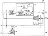
- FIG. 1 is a block diagram schematically showing a configuration example of an inverter control apparatus and a motor drive system according to a first embodiment.
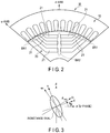
- FIG. 2 is a view for explaining a configuration example of a part of a synchronous motor shown in FIG. 1 .
- FIG. 3 is a view for explaining definitions of a d-axis, a q-axis, and an estimated rotation coordinate system (a dc-axis, a qc-axis) in embodiments.
- FIG. 4 is a view showing examples of a q-axis static inductance and a d-axis static inductance in a case where an electric motor is energized.
- FIG. 5 is a view showing examples of a q-axis dynamic inductance and a d-axis dynamic inductance in a case where an electric motor is energized.
- FIG. 6 is a block diagram schematically showing a configuration example of a command generator shown in FIG. 1 .
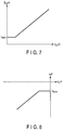
- FIG. 7 is a view for explaining an example of operations of a lower-limit setting unit shown in FIG. 6 .
- FIG. 8 is a view for explaining an example of operations of a limiting unit shown in FIG. 6 .
- FIG. 9 is a block diagram schematically showing a configuration example of a high-frequency-voltage superposing unit shown in FIG. 1 .
- FIG. 10 is a view for explaining an example of a relationship between an input and an output of the high-frequency-voltage superposing unit shown in FIG. 1 .
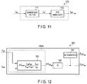
- FIG. 11 is a block diagram schematically showing a configuration example of a high-frequency-current detector shown in FIG. 1 .
- FIG. 12 is a block diagram schematically showing a configuration example of a rotation-phase-angle/speed estimator shown in FIG. 1 .
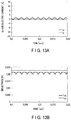
- FIG. 13A is a view showing examples of a d-axis electric current and a q-axis electric current in a case where an electric current flowing through a synchronous motor is equal to approximately zero.
- FIG. 13B is a view showing examples of a d-axis dynamic inductance and a q-axis dynamic inductance in a case where an electric current flowing through a synchronous motor is equal to approximately zero.
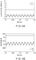
- FIG. 14A is a view showing examples of a d-axis electric current and a q-axis electric current in a case where a fundamental wave current synchronous with a speed of a rotor is supplied to a synchronous motor.
- FIG. 14B is a view showing examples of a d-axis dynamic inductance and a q-axis dynamic inductance in a case where the d-axis electric current and the q-axis electric current shown in FIG. 14A are supplied to a synchronous motor.
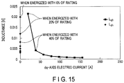
- FIG. 15 is a view showing an example of dynamic inductance characteristics in a case where a phase-angle error estimation value is 90°.
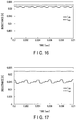
- FIG. 16 is a view showing examples of a d-axis dynamic inductance and a q-axis dynamic inductance in a case where a rotation-phase-angle error estimation value is equal to 90° and an electric current flowing through a synchronous motor is equal to approximately zero.
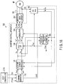
- FIG. 17 is a view showing examples of a d-axis dynamic inductance and a q-axis dynamic inductance in a case where a rotation-phase-angle error estimation value is equal to 90° and an electric current is supplied to a synchronous motor toward a dc-axis.
- FIG. 18 is a block diagram schematically showing a configuration example of an inverter control apparatus and a motor drive system according to a second embodiment.
- FIG. 19 is a block diagram schematically showing a configuration example of a rotation-phase-angle/speed estimator shown in FIG. 18 .
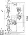
- FIG. 20 is a block diagram schematically showing a configuration example of an inverter control apparatus and a motor drive system according to a third embodiment.
- FIG. 21 is a block diagram schematically showing a configuration example of a command generator shown in FIG. 20 .
- FIG. 22 is a view for explaining another configuration example of a threshold determining unit shown in FIG. 21 .
- FIG. 23 is a block diagram schematically showing a configuration example of a rotation-phase-angle/speed estimator shown in FIG. 20 .
- FIG. 24 is a block diagram schematically showing a configuration example of a high-frequency-voltage superposing unit shown in FIG. 20 .
- FIG. 25 is a block diagram schematically showing a configuration example of an inverter control apparatus and a motor drive system according to a fourth embodiment.
- FIG. 26 is a block diagram schematically showing a configuration example of an electric-current controller shown in FIG. 25 .
- FIG. 27 is a block diagram schematically showing a comparative example of an electric-current controller.
- An inverter control apparatus comprises an inverter main circuit that drives a synchronous motor; an electric-current detector that detects an electric current flowing between the inverter main circuit and the synchronous motor; a command generator that generates an electric-current command value of an output electric current that is output from the inverter main circuit to the synchronous motor, in accordance with a torque command that is supplied externally; and an electric-current controller that generates a voltage command value for the inverter main circuit so that the electric-current command value and a detected electric-current value detected in the electric-current detector are equal to each other.
- the command generator generates the electric-current command value so that a fundamental wave current that is equal to or greater than a threshold is supplied to the synchronous motor, in driving the inverter main circuit.
- FIG. 1 is a block diagram schematically showing a configuration example of an inverter control apparatus and a motor drive system according to the first embodiment.
- the motor drive system includes a synchronous motor M, an inverter main circuit INV, an inverter control apparatus 100 , and a host controller CTR.
- the inverter control apparatus 100 includes an electric-current detector SS, a command generator 110 , an electric-current controller 120 , a high-frequency-voltage superposing unit 130 , coordinate converters 140 and 160 , a modulator 150 , a high-frequency-current detector 170 , a rotation-phase-angle/speed estimator (first rotation-phase-angle/speed estimator) 180 , and an adder 190 .
- the synchronous motor M is a synchronous motor including a rotor which is magnetically salient, and is a synchronous reluctance motor, for example. Also, as the synchronous motor M, a permanent-magnet synchronous motor using a magnet, a wound-field synchronous motor which supplies magnetic flux of a field using a secondary winding, or the like can be also employed. In the present embodiment, an example in which a synchronous reluctance motor is employed as the synchronous motor M will be described.
- the inverter main circuit INV includes a direct-current power source (direct-current load) and two switching elements for each of a U-phase, a V-phase, and a W-phase.
- the two switching elements for each phase are connected in series between a direct-current line which is connected to a positive pole of the direct-current power source, and a direct-current line which is connected to a negative pole of the direct-current power source. Operations of the switching elements of the inverter main circuit INV are controlled by a gate command output from the modulator 150 .
- the inverter main circuit INV is a three-phase alternating-current inverter which outputs a U-phase electric current I u , a V-phase electric current I v , and a W-phase electric current I w at a predetermined frequency, to the synchronous motor M which is an alternating-current load, in accordance with a gate command. Also, the inverter main circuit INV can charge a secondary battery which is a direct-current power source, with electric power generated in the synchronous motor M.
- FIG. 2 is a view for explaining a configuration example of a part of the synchronous motor shown in FIG. 1 .
- a stator 10 and a rotor 20 of the synchronous motor M are formed of a combination of a plurality of elements shown in FIG. 2 , for example.
- the synchronous motor M is a synchronous reluctance motor which is magnetically salient.
- the synchronous motor M includes the stator 10 and the rotor 20 .
- the rotor 20 includes air gaps 21 , an outer circumference bridge BR 1 , and a center bridge BR 2 .
- the center bridge BR 2 is placed on a line connecting a circumference and a center of the rotor 20 . It is noted that the line on which the center bridge BR 2 is placed is a d-axis.
- the outer circumference bridge BR 1 is placed between a circumference of the rotor 20 and the air gaps 21 .
- six air gaps 21 each extending from a circumferential portion to a central portion of the rotor 20 are provided.
- the air gaps 21 extend between the center bridge BR 2 and the outer circumference bridge BR 1 in such a manner that they are line-symmetric with respect to a d-axis.
- FIG. 3 is a view for explaining definitions of a d-axis, a q-axis, and an estimated rotation coordinate system (a dc-axis, a qc-axis) in the embodiments.
- a d-axis is a vector axis which rotates through a rotation phase angle ⁇ with respect to a a-axis (U-phase) of a ⁇ fixed coordinate system
- a q-axis is a vector axis which is orthogonal to a d-axis at an electric angle.
- the synchronous motor M is magnetically salient
- a d-axis is a vector axis on which a static inductance becomes the lowest in the rotor 20 of the synchronous motor M
- a q-axis is a vector axis on which a static inductance becomes the highest in the rotor 20 of the synchronous motor M.
- a dcqc estimated rotation coordinate system corresponds to a d-axis and a q-axis in an estimated position of the rotor 20 .
- a dc-axis is a vector axis which rotates through an angle of a rotation-phase-angle estimation value ⁇ est with respect to a ⁇ -axis
- a qc-axis is a vector axis which is orthogonal to a dc-axis at an electric angle.
- a dc-axis is a vector axis which rotates through an angle of an estimated error ⁇ with respect to a d-axis
- a qc-axis is a vector axis which rotates through an angle of the estimated error ⁇ with respect to a q-axis.
- FIG. 4 is a view showing examples of a q-axis static inductance and a d-axis static inductance in a case where an electric motor is energized.
- FIG. 5 is a view showing examples of a q-axis dynamic inductance and a d-axis dynamic inductance in a case where an electric motor is energized.
- a static inductance is an inductance related to a fundamental wave current flowing through the synchronous motor M
- a dynamic inductance is an inductance related to a harmonic current flowing through the synchronous motor M.
- a static inductance corresponds to an amount of change ( ⁇ /I) of magnetic flux ⁇ which is produced by a certain fundamental-wave-current value (I).
- a dynamic inductance corresponds to an amount of change ( ⁇ / ⁇ I) of fluctuation ⁇ of magnetic flux related to fluctuation ⁇ I of a certain harmonic current.
- a dynamic inductance is equal to or lower than a static inductance. This is because a dynamic inductance is correlated with magnetic saturation of the bridges BR 1 and BR 2 of the rotor 20 and a static inductance is correlated with magnetic saturation of an electromagnetic steel plate through which main magnetic flux passes. Specifically, it indicates that magnetic saturation occurs earlier in the bridges BR 1 and BR 2 of the rotor 20 when an electric current is supplied to the synchronous motor M.
- each of a d-axis dynamic inductance and a q-axis dynamic inductance tends to converge on a predetermined value as magnetic saturation proceeds.
- the inverter control apparatus and the motor drive system according to the present embodiment control an electric current and estimate a magnetic pole based on the above-described characteristics of the synchronous motor M.
- the electric-current detector SS detects alternating-current values of at least two phases out of three-phase alternating currents (response currents) i u , i v , and i w which flow to the synchronous motor M, and supplies them to the inverter control apparatus 100 .
- the coordinate converter 160 is a vector transformation unit which converts the response current values i u and i w which are supplied from the electric-current detector SS and appear in a three-phase fixed coordinate system into response current values I dc and I qc in a dcqc estimated rotation coordinate system using a phase-angle estimation value ⁇ est supplied from the rotation-phase-angle/speed estimator 180 .
- the coordinate converter 160 supplies the dc-axis electric-current value I dc and the qc-axis electric-current value I qc to the electric-current controller 120 .
- the command generator 110 receives a torque command T* and an ON/OFF command Gst from the host controller CTR, and generates and outputs a d-axis electric-current command I dref and a q-axis electric-current command I qref . Also, the command generator 110 receives a carrier frequency fcar from the host controller CTR and outputs a carrier command CAR. Further, the command generator 110 sets an upper limit to an amplitude of the d-axis electric-current command value I dref .
- FIG. 6 is a block diagram schematically showing a configuration example of the command generator shown in FIG. 1 .
- the command generator 110 includes an electric-current command generator 111 , a limiting unit 112 , a time delay unit 113 , a carrier generator 114 , an electric-current corrector 115 , and an L q corrector 116 .
- the electric-current command generator 111 calculates a dq-axis electric-current command value which minimizes copper loss, using a map, approximation, a theoretical relation, or the like, for example.
- the electric-current command generator 111 outputs one of calculated dq-axis electric-current command values, as a first d-axis electric-current command i d1 *.
- a fundamental wave current of a magnitude which is equal to or greater than a predetermined threshold is supplied in a ⁇ d-axis relative to the rotor 20 of the synchronous motor M.
- the limiting unit 112 calculates an absolute value of a second d-axis electric-current command i d2 * while setting an absolute value of the first d-axis electric-current command i d1 * to be equal to or lower than a lower limit i dlim , and calculates and outputs the second d-axis electric-current command i d2 * so that a sign of the second d-axis electric-current command i d2 * is identical to a sign of the first d-axis electric-current command i d1 *.
- the limiting unit 112 includes an absolute-value calculator ABS, a lower-limit setting unit LIM, a sign determining unit 112 A, and a multiplier 112 B.
- the absolute-value calculator ABS receives the first d-axis electric-current command i d1 * from the electric-current command generator 111 , and calculates and outputs an absolute value of the first d-axis electric-current command i d1 *.
- FIG. 7 is a view for explaining an example of operations of the lower-limit setting unit shown in FIG. 6 .
- the lower-limit setting unit LIM receives an absolute value of the first d-axis electric-current command i d1 * from the absolute-value calculator ABS, and outputs an absolute value of the second d-axis electric-current command i d2 * which is equal to an absolute value of the first d-axis electric-current command i d1 * when an absolute value of the first d-axis electric-current command i d1 * is equal to or greater than the lower limit i dlim .
- the lower-limit setting unit LIM outputs an absolute value of the second d-axis electric-current command i d2 * which is equal to the lower limit i dlim when an absolute value of the first d-axis electric-current command i d1 * is smaller than the lower limit i dlim .
- the sign determining unit 112 A receives the first d-axis electric-current command i d1 * from the electric-current command generator 111 , and determines whether the first d-axis electric-current command i d1 * is greater than zero, or equal to or smaller than zero.
- the sign determining unit 112 A outputs “+1” when the first d-axis electric-current command i d1 * is greater than zero, and outputs “ ⁇ 1” when the first d-axis electric-current command i d1 * is equal to or smaller than zero.
- the multiplier 112 B multiplies an absolute value of the second d-axis electric-current command i d2 * output from the lower-limit setting unit LIM and an output value of the sign determining unit 112 A, and outputs its result.
- FIG. 8 is a view for explaining an example of operations of the limiting unit shown in FIG. 6 .
- the limiting unit 112 sets a lower limit to an amplitude of a d-axis electric current and outputs the second d-axis electric-current command i d2 * as shown in FIG. 8 .
- the electric-current corrector 115 receives the second d-axis electric-current command i d2 * from the limiting unit 112 , and calculates a q-axis electric-current command i q * using the following [Expression A].
- L d represents a d-axis inductance
- p represents the number of pole pairs
- L q represents a q-axis inductance (which is a value corrected by the L q corrector 116 ).
- the L q (q-axis inductance) corrector 116 receives the q-axis electric-current command I qref calculated in the electric-current corrector 115 , calculates the q-axis inductance L q using a map or approximation, and outputs its result to the electric-current corrector 115 .
- the q-axis electric-current command I qref is a value based on the torque command T* and a second d-axis electric-current command i d2 *, to be a direct-current value.
- the time delay unit 113 outputs the ON/OFF command Gst while delaying the ON/OFF command Gst by a predetermined time.
- the ON/OFF command Gst is a control command for a logical-AND operation unit S 1 which changes electrical connection of a path over which a torque command is supplied to the electric-current command generator 111 , and a logical-AND operation unit S 2 which changes electrical connection of a path over which the second d-axis electric-current command i d2 * is output as the d-axis electric-current command I dref from the limiting unit 112 .
- the ON/OFF command Gst is supplied to a logical-AND operation unit S 3 which changes electrical connection of a path over which a q-axis electric-current command is output from the electric-current corrector 115 via the time delay unit 113 .
- the q-axis electric-current command I qref is output while being delayed with respect to the d-axis electric-current command I dref by at least a time required for calculations in the L q corrector 116 and the electric-current corrector 115 .
- the above-described electric-current corrector 115 allows the electric-current command values I dref and I qref which are output from the electric-current command generator 111 to serve as electric-current command values which generate torque in accordance with the torque command T* in the synchronous motor M. Accordingly, even if a lower limit to an electric-current command value is set by the limiting unit 112 , torque as is expected is output, so that a speed control system can be prevented from becoming unstable.
- the carrier generator 114 generates and outputs the carrier command CAR used in the modulator 150 , based on the carrier frequency fcar which is supplied externally.
- a carrier command is a triangular wave at a predetermined frequency.
- the electric-current controller 120 includes a PI (proportional-plus-integral) controller, for example.
- the electric-current controller 120 compares the dc-axis electric-current value I dc and the qc-axis electric-current value I qc which are supplied from the coordinate converter 160 , with the d-axis electric-current command I dref and the q-axis electric-current command I qref , and calculates and outputs voltage commands V dc and V qc so that the dc-axis electric-current value I dc and the d-axis electric-current command I dref are equal to zero and a difference between the qc-axis electric-current value I qc and the q-axis electric-current command I qref is equal to zero.
- PI proportional-plus-integral
- the high-frequency-voltage superposing unit 130 receives the carrier command CAR from the command generator 110 , generates a high-frequency voltage at an arbitrary frequency for a dc-axis, a qc-axis, or both of those axes, and outputs its result to the adder 190 and the rotation-phase-angle/speed estimator 180 .
- the high-frequency-voltage superposing unit 130 outputs a dc-axis high-frequency voltage V dh .
- FIG. 9 is a block diagram schematically showing a configuration example of the high-frequency-voltage superposing unit shown in FIG. 1 .
- FIG. 10 is a view for explaining an example of a relationship between an input and an output of the high-frequency-voltage superposing unit shown in FIG. 1 .
- the high-frequency-voltage superposing unit 130 includes a synchronous-pulse generator 131 and a high-frequency-voltage synchronization unit (logical-AND operation unit) 132 .
- the synchronous-pulse generator 131 generates a synchronous pulse which is synchronous with the carrier command CAR supplied from the command generator 110 , and outputs it to the high-frequency-voltage synchronization unit 132 .
- the high-frequency-voltage synchronization unit 132 combines a voltage V h which is an internally-generated direct-current-voltage command value of a predetermined magnitude, with a synchronous pulse, and outputs a resultant voltage.
- V dh output from the high-frequency-voltage superposing unit 130 is a high-frequency-voltage command which has a predetermined amplitude V h and a high-frequency voltage period (I/f dh ) which is synchronous with a period (I/fcar) of the carrier command CAR.
- the adder 190 which is placed in a stage subsequent to the electric-current controller 120 , updates the voltage command V dc output from the electric-current controller 120 by adding the high-frequency voltage V dh to the voltage command V dc , and outputs its result.
- the coordinate converter 140 is a vector transformation unit which converts the voltage commands V dc and V qc of the dcqc estimated rotation coordinate system into voltage commands V u *, V v *, and V w * of the three-phase fixed coordinate system, using the phase-angle estimation value ⁇ est supplied from the rotation-phase-angle/speed estimator 180 .
- the voltage commands V dc and V qc supplied from the coordinate converter 140 have values based on the electric-current commands I dref and I qref by which a fundamental wave current of a predetermined magnitude is supplied to the synchronous motor M in a ⁇ d-axis direction.
- the modulator 150 generates gate commands V u_PWM , V v_PWM , and V w_PWM by modulating the voltage commands V u *, V v *, and V w * in accordance with the carrier command CAR, and outputs them to the inverter main circuit INV.
- the carrier command CAR is a triangular wave at a predetermined frequency
- the modulator 150 accomplishes PWM modulation control by comparing a triangular wave and a voltage command.
- FIG. 11 is a block diagram schematically showing a configuration example of a high-frequency-current detector shown in FIG. 1 .
- the high-frequency-current detector 170 includes a bandpass filter 171 and a FFT analyzer 172 .
- the bandpass filter 171 receives the dc-axis response current value (output electric current) I dc and the qc-axis response current value (output electric current) I qc from the coordinate converter 160 , and extracts and outputs a high-frequency electric-current value i qc ′ at a frequency equal to a frequency f dh of the high-frequency voltage V dh which is superposed on the dc-axis voltage command V dc by the adder 190 .
- the FFT analyzer 172 carries out FFT analysis of the high-frequency electric-current value i qc ′, detects a high-frequency-current amplitude I qch , and outputs it to the rotation-phase-angle/speed estimator 180 , for example.
- the rotation-phase-angle/speed estimator 180 calculates and outputs the rotation-phase-angle estimation value ⁇ est and the rotation-speed estimation value ⁇ est using the high-frequency-current amplitude I qch and the high-frequency voltage V dh .
- FIG. 12 is a block diagram schematically showing a configuration example of the rotation-phase-angle/speed estimator shown in FIG. 1 .
- the rotation-phase-angle/speed estimator 180 includes a first phase-angle error estimator 180 A including a rotation-phase-angle error calculator 181 , a PI (proportional-plus-integral) controller 182 , and an integrator 183 .
- v d represents a d-axis voltage
- v q represents a q-axis voltage
- i d represents a d-axis electric current
- i q represents a q-axis electric current
- R represents coil resistance of an armature
- ⁇ e represents an angular velocity of an electrical angle
- L d represents a d-axis inductance
- L q represents a q-axis inductance
- the rotation-phase-angle error calculator 181 calculates and outputs the rotation-phase-angle error ⁇ est using the above-described characteristics of rotation-angle dependence.
- the PI controller 182 calculates and outputs the rotation-speed estimation value ⁇ est by exercising PI control so that the rotation-phase-angle error estimation value ⁇ est is zero.
- the integrator 183 calculates and outputs the rotation phase angle ⁇ est by integrating the rotation-speed estimation value ⁇ est .
- L da or L qa represents an inductance related to a fundamental wave current (i.e., static inductance)
- L dh or L qh represents an inductance related to a change in an electric current (i.e., dynamic inductance).
- a high-frequency electric current in this case can be expressed by the following [Expression 8].
- FIG. 13A is a view showing examples of a d-axis electric current and a q-axis electric current in a case where an electric current flowing through a synchronous motor is approximately zero.
- FIG. 13B is a view showing examples of a d-axis dynamic inductance and a q-axis dynamic inductance in a case where an electric current flowing through a synchronous motor is approximately zero.
- a d-axis electric current greatly varies due to superposition of a high-frequency voltage on a d-axis voltage command.
- a salient-pole difference is extremely small. Specifically, in a case where no electric current is supplied to the synchronous motor M (an electric current is approximately zero), magnetic saturation of the synchronous motor M does not occur, so that a salient-pole difference between the d-axis dynamic inductance L dh and the q-axis dynamic inductance L qh is approximately zero. Accordingly, a denominator in the foregoing [Expression 12] inevitably becomes equal to approximately zero.
- a fundamental wave current which is synchronous with a rotor speed and has a magnitude equal to or greater than a threshold is supplied in a ⁇ d-axis direction.
- a magnitude of a d-axis electric current being supplied to the synchronous motor M is set so as to allow a d-axis dynamic inductance to be sufficiently saturated, and a limit (i dmini ) of a d-axis electric current being supplied is set such that a d-axis dynamic inductance is equal to or lower than a d-axis static inductance at a rated operation time, for example.
- FIG. 14A is a view showing examples of a d-axis electric current and a q-axis electric current in a case where a fundamental wave current synchronous with a rotor speed is supplied to a synchronous motor.
- FIG. 14B is a view showing examples of a d-axis dynamic inductance and a q-axis dynamic inductance in a case where the d-axis electric current and the q-axis electric current shown in FIG. 14A are supplied to a synchronous motor.
- FIGS. 14A and 14B it is found that when a fundamental wave current which is synchronous with a rotor speed and has a predetermined magnitude is supplied in a ⁇ d-axis direction, a rotor of the synchronous motor M is magnetically saturated sufficiently and a magnetic-salient-pole difference becomes greater than that in a case where an electric current is zero.
- FIG. 15 is a view showing an example of dynamic-inductance characteristics in a case where a phase-angle error estimation value is 90°.
- a fundamental wave current is supplied to not only a d-axis but also a q-axis in some cases, depending on when an inverter is activated. Also in such cases, as shown in FIG. 15 , by supplying a fundamental wave current toward a dc-axis, it is possible to allow saturation of a d-axis dynamic inductance to proceed on account of leakage of q-axis magnetic flux, so that a magnetic-salient-pole difference can be obtained.
- FIG. 16 is a view showing examples of a d-axis dynamic inductance and a q-axis dynamic inductance in a case where the rotation-phase-angle error estimation value is 90° and an electric current flowing through a synchronous motor is approximately zero.
- FIG. 17 is a view showing examples of a d-axis dynamic inductance and a q-axis dynamic inductance in a case where the rotation-phase-angle error estimation value is 90° and an electric current is supplied to a synchronous motor toward a dc-axis.
- FIGS. 16 and 17 indicate that a magnetic-salient-pole difference in a case where the synchronous motor M was not energized was smaller than that in a case where a predetermined electric current was supplied to the synchronous motor M toward a dc-axis. Accordingly, even when an error occurred in estimation of a phase angle, a magnetic-salient-pole difference could be obtained by a method in which a high-frequency voltage is superposed on a voltage command value, and a rotation-phase-angle estimation value and a speed estimation value could be calculated.
- an inverter control apparatus and a motor drive system which accurately control an electric current can be provided.
- a method is not limited to the foregoing one.
- the same effects as produced in the present embodiment can be produced by any method that allows calculation of a rotation-phase-angle estimation value, such as a method in which both of a dc-axis electric current and a qc-axis electric current are detected, or a method in which a high-frequency voltage is superposed on both of a dc-axis voltage command and a qc-axis voltage command.
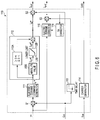
- FIG. 18 is a block diagram schematically showing a configuration example of the inverter control apparatus and the motor drive system according to the second embodiment.
- the motor drive system includes a synchronous motor M, an inverter main circuit INV, an inverter control apparatus 100 , and a host controller CTR.
- the inverter control apparatus 100 includes an electric-current detector SS, a command generator 110 , an electric-current controller 120 , coordinate converters 140 and 160 , a modulator 150 , and a rotation-phase-angle/speed estimator (second rotation-phase-angle/speed estimator) 180 .
- the synchronous motor M is a synchronous motor including a rotor which is magnetically salient, and is a synchronous reluctance motor, for example.
- a permanent-magnet synchronous motor using a magnet a permanent-magnet synchronous motor using a magnet
- a synchronous reluctance motor a wound-field synchronous motor which supplies magnetic flux of a field using a secondary winding, or the like can be employed.
- a synchronous reluctance motor is employed as the synchronous motor M will be described.
- the inverter main circuit INV includes a direct-current power source (direct-current load) and two switching elements for each of a U-phase, a V-phase, and a W-phase.
- the two switching elements for each phase are connected in series between a direct-current line which is connected to a positive pole of the direct-current power source, and a direct-current line which is connected to a negative pole of the direct-current power source. Operations of the switching elements of the inverter main circuit INV are controlled by a gate command received from the modulator 150 .
- the inverter main circuit INV is a three-phase alternating-current inverter which outputs a U-phase electric current I u , a V-phase electric current I v , and a W-phase electric current I w at a predetermined frequency, to the synchronous motor M which is an alternating-current load, in accordance with a gate command. Also, the inverter main circuit INV can charge a secondary battery which is a direct-current power source, with electric power generated in the synchronous motor M.
- a method in which a set value of a motor parameter is used in calculation for estimation of a rotation-phase-angle error is employed.
- the method of calculating a rotation-phase-angle estimation value used in the present embodiment is suitable for estimation of a rotation phase angle in a case where the synchronous motor M rotates at a high speed.
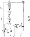
- FIG. 19 is a block diagram schematically showing a configuration example of the rotation-phase-angle/speed estimator shown in FIG. 18 .
- the rotation-phase-angle/speed estimator 180 calculates a rotation-phase-angle error ⁇ est using voltage command V dc and V qc , detected electric-current values I dc and I qc (or electric-current commands I dref and I qref ), and a set value L da_set of a static dynamic inductance.
- the rotation-phase-angle/speed estimator 180 includes a second phase-angle error estimator 180 B which calculates the rotation-phase-angle error estimation value ⁇ est using an extended induced voltage, for example, a PI controller 187 , and an integrator 188 .
- [Expression 18] can be written as [Expression 19] because a set value is used as a motor parameter actually.
- R _set represents a set value of resistance
- L d_set represents a set value of a d-axis inductance
- the second phase-angle error estimator 180 B calculates the rotation-phase-angle error estimation value ⁇ est using the foregoing [Expression 20].
- a multiplier B 2 multiplies a qc-axis electric-current command I qc and a rotation-speed estimation value ⁇ est , and outputs its result.
- An output of the multiplier B 2 is supplied to an inductance setting unit 184 .
- the inductance setting unit 184 multiplies an input value (I qc ⁇ est ) and a set value L da_set of d-axis static inductance, and outputs its result to an adder B 1 .
- the adder B 1 adds the dc-axis voltage command V dc and an output (I qc ⁇ est ⁇ L da_set ) of the inductance setting unit 184 , and outputs its result.
- a multiplier B 4 multiplies the dc-axis electric-current command I dc and the rotation-speed estimation value ⁇ est , and outputs its result.
- An output of the multiplier B 4 is supplied to an inductance setting unit 185 .
- the inductance setting unit 185 multiplies an input value (I dc ⁇ est ) and the set value L da_set of d-axis static inductance, and outputs its result to a subtracter B 3 .
- the subtracter subtracts an output (I dc ⁇ est ⁇ L da_set ) of the inductance setting unit 185 from the qc-axis voltage command V qc , and outputs its result.
- a divider B 5 divides an output of the subtracter B 3 by an output of the adder B 1 , and outputs its result to an arc-tangent calculation unit 186 .
- the arc-tangent calculation unit 186 calculates an arc tangent of a value output from the divider, and outputs its result as the rotation-phase-angle error estimation value ⁇ est .
- the PI controller 187 exercises PI control in such a manner that the rotation-phase-angle error estimation value ⁇ est converges on zero, and outputs the rotation-speed estimation value ⁇ est .
- the integrator 188 integrates the rotation-speed estimation value ⁇ est output from the PI controller 187 , and calculates and outputs the rotation-phase-angle estimation value ⁇ est .
- an electric current is supplied while setting a limit to a command value of a d-axis electric current for which a static inductance greatly varies due to magnetic saturation, so that magnetic saturation in a d-axis direction always proceeds.
- a method is not limited to one using the foregoing equations.
- the same effects are produced also by a method in which a rotation phase angle is estimated based on a result of subtraction of a model voltage (a voltage calculated from a voltage command value using a motor model, which is synonymous with a feedforward voltage).
- an inverter control apparatus and a motor drive system which can accurately control an electric current can be provided.
- an inverter control apparatus and a motor drive system according to a third embodiment will be described with reference to the drawings.
- a method of estimating a rotation-phase-angle/speed is changed depending on a speed.
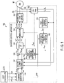
- FIG. 20 is a block diagram schematically showing a configuration example of the inverter control apparatus and the motor drive system according to the third embodiment.
- a command generator 110 outputs a control changeover signal flg based on a rotation-speed estimation value ⁇ est which is supplied from a rotation-phase-angle/speed estimator 180 .
- the rotation-phase-angle/speed estimator 180 changes a method of estimating a rotation phase angle or speed based on a value of the control changeover signal flg.
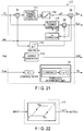
- FIG. 21 is a block diagram schematically showing a configuration example of the command generator 110 shown in FIG. 20 .
- the command generator 110 further includes a lowpass filter FLT and a threshold determining unit 117 , in addition to the elements in the command generator 110 in the above-described first embodiment. It is noted that a limiting unit 112 shown in FIG. 21 is configured in the same manner as the limiting unit 112 shown in FIG. 6 .
- the lowpass filter FLT receives the rotation-speed estimation value ⁇ est , removes a high-frequency component therefrom, and outputs its result to the threshold determining unit 117 .
- the threshold determining unit 117 compares the rotation-speed estimation value ⁇ est which is input, with a predetermined threshold, and outputs “1” as the control changeover signal flg when the rotation-speed estimation value ⁇ est is equal to or smaller than the predetermined threshold, while outputting “0” as the control changeover signal flg when the rotation-speed estimation value ⁇ est is smaller than the predetermined threshold.
- FIG. 22 is a view for explaining another configuration example of the threshold determining unit shown in FIG. 21 .
- a threshold (first threshold Th 1 ) used for switching the control changeover signal flg from “0” to “1” (changing a rotation speed from a high speed to a low speed) and a threshold (second threshold Th 2 larger than the first threshold Th 1 ) used for switching the control changeover signal flg from “1” to “0” (changing a rotation speed from a low speed to a high speed) are made different from each other.
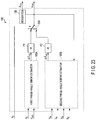
- FIG. 23 is a block diagram schematically showing a configuration example of the rotation-phase-angle/speed estimator shown in FIG. 20 .
- the rotation-phase-angle/speed estimator 180 includes a first phase-angle error estimator 180 A which calculates a rotation-phase-angle error estimation value ⁇ est using a high-frequency voltage signal and a high-frequency electric current, a second phase-angle error estimator 180 B which calculates the rotation-phase-angle error estimation value ⁇ est using a voltage command and an electric-current command or a detected electric-current value, P controllers P 1 and P 2 , a switch SW, and an integrator 188 .
- the first phase-angle error estimator 180 A corresponds to the first phase-angle error estimator 180 A of the rotation-phase-angle/speed estimator 180 of the first embodiment shown in FIG. 11 .
- the second phase-angle error estimator 180 B corresponds to the second phase-angle error estimator 180 B of the rotation-phase-angle/speed estimator 180 of the second embodiment shown in FIG. 18 .
- the PI controller P 1 includes a PI controller which calculates a rotation-speed estimation value so that the rotation-phase-angle error estimation value ⁇ est output from the first phase-angle error estimator 180 A is equal to zero, and outputs its result.
- the PI controller P 2 includes a PI controller which calculates a rotation-speed estimation value ⁇ est so that the rotation-phase-angle error estimation value ⁇ est output from the second phase-angle error estimator 180 B is equal to zero, and outputs its result.
- the switch SW changes electrical connection between an input terminal and an output terminal in accordance with a value of the control changeover signal flg.
- the switch SW includes a first input terminal to which the rotation-speed estimation value ⁇ est supplied from the PI controller P 1 is input, a second input terminal to which the rotation-speed estimation value ⁇ est supplied from the PI controller P 2 is input, and an output terminal.
- the switch SW electrically connects the first input terminal and the output terminal when the control changeover signal flg is “1”, and electrically connects the second input terminal and the output terminal when the control changeover signal flg is “0”.
- the integrator 188 integrates the rotation-speed estimation value ⁇ est output from the switch SW, and outputs the rotation-phase-angle estimation value ⁇ est .
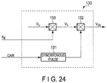
- FIG. 24 is a block diagram schematically showing a configuration example of the high-frequency-voltage superposing unit shown in FIG. 20 .
- the high-frequency-voltage superposing unit 130 further includes a logical-AND operation unit 133 which outputs a logical AND of the control changeover signal flg and a voltage V h serving as a command for a direct-current voltage of a predetermined magnitude.
- An output of the logical-AND operation unit 133 is supplied to a logical-AND operation unit 132 , and the voltage V h is output only when the control changeover signal flg is “1”.
- a high-frequency voltage V dh is output only when the rotation-phase-angle error estimation value ⁇ est is calculated.
- a noise is caused due to superposition of a high-frequency signal.
- an estimation method is changed from a method in which superposition of a high-frequency signal is used, so that a noise caused due to superposition of a high frequency can be reduced.
- an inverter control apparatus and a motor drive system which accurately control an electric current can be provided.
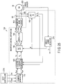
- FIG. 25 is a block diagram schematically showing a configuration example of the inverter control apparatus and the motor drive system according to the fourth embodiment.
- the motor drive system includes a synchronous motor M, an inverter main circuit INV, an inverter control apparatus 100 , and a host controller CTR.
- the inverter control apparatus 100 includes an electric-current detector SS, a command generator 110 , an electric-current controller 120 , coordinate converters 140 and 160 , a modulator 150 , an angle/speed detector 210 , and an angle sensor 200 .
- the synchronous motor M is a synchronous motor including a rotor which is magnetically salient, and is a synchronous reluctance motor, for example.
- a permanent-magnet synchronous motor using a magnet a permanent-magnet synchronous motor using a magnet
- a synchronous reluctance motor a wound-field synchronous motor which supplies magnetic flux of a field using a secondary winding, or the like can be employed.
- a synchronous reluctance motor is employed as the synchronous motor M will be described.
- the inverter main circuit INV includes a direct-current power source (direct-current load) and two switching elements for each of a U-phase, a V-phase, and a W-phase.
- the two switching elements for each phase are connected in series between a direct-current line which is connected to a positive pole of the direct-current power source, and a direct-current line which is connected to a negative pole of the direct-current power source. Operations of the switching elements of the inverter main circuit INV are controlled by a gate command received from the modulator 150 .
- the inverter main circuit INV is a three-phase alternating-current inverter which outputs a U-phase electric current I u , a V-phase electric current I v , and a W-phase electric current I w at a predetermined frequency, to the synchronous motor M which is an alternating-current load, in accordance with a gate command. Also, the inverter main circuit INV can charge a secondary battery which is a direct-current power source, with electric power generated in the synchronous motor M.
- the angle sensor 200 is attached to the synchronous motor M, and detects an angle of a rotor of the synchronous motor M.
- a resolver can be used, for example.
- the angle/speed detector 210 corrects an angle of a rotor of the synchronous motor M, the angle being detected by the angle sensor 200 , and calculates a rotation phase angle ⁇ and a rotation speed ⁇ .
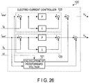
- FIG. 26 is a block diagram schematically showing a configuration example of the electric-current controller shown in FIG. 25 .
- the electric-current controller 120 includes a PI controller 122 which outputs a d-axis voltage command V d so that a difference between a d-axis electric-current command I dref and a d-axis electric-current I d is equal to zero, a PI controller 123 which outputs a q-axis voltage command V q so that a difference between a q-axis electric-current command I qref and a q-axis current I q is equal to zero, and a feed-forward-voltage calculation unit 121 .
- an object being controlled (plant) is regarded as a first-order lag system in some cases.
- the synchronous motor M as a first-order lag system
- a voltage term (interference term) due to reaction of an armature is compensated for in a feedforward manner.
- a voltage equation of the synchronous motor M is the foregoing [Expression 1], and a feedforward voltage can be calculated by the following [Expression 23].
- [Expression 24] means an output of an electric-current PI controller.
- a d-axis loop transfer function in a case where PI control is exercised is represented by the following [Expression 28].
- i dRef K pd ⁇ ( 1 + 1 s ⁇ ⁇ ⁇ A ) ⁇ 1 R ⁇ 1 ( 1 + s ⁇ ⁇ ⁇ d ) 1 + K pd ⁇ ( 1 + 1 s ⁇ ⁇ ⁇ A ) ⁇ 1 R ⁇ 1 ( 1 + s ⁇ ⁇ ⁇ d ) ⁇ i d ⁇ [ Expression ⁇ ⁇ 28 ]
- ⁇ A represents an arbitrary time constant
- s:p represents a differential operator
- K pd represents a d-axis proportional gain
- L da is equal to L da_set and L qa is equal to L qa_set at a time when [Expression 25] is provided above, and those values greatly vary depending on operating conditions (magnetic saturation) as described above. In a case where those values are not equal, a control system cannot be designed as a plant having an arbitrary time constant, so that a response as designed cannot be obtained.
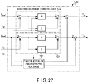
- FIG. 27 is a block diagram schematically showing a comparative example of an electric-current controller.
- the electric-current controller 120 shown in FIG. 27 is configured such that a gain is variable depending on magnetic saturation, in order to obtain a response as designed. Since variation depending on operating conditions becomes particularly significant on a d-axis where a static inductance greatly varies due to magnetic saturation, a d-axis electric-current command I dref is supplied to a proportional controller P and an integral controller I of the PI controller 122 .
- a d-axis dynamic inductance L dh should be known in order to achieve such design, and those values, like the above-described static inductance, greatly vary under influence of magnetic saturation. Variation of a q-axis dynamic inductance L qh due to magnetic saturation is smaller than variation of the d-axis dynamic inductance L dh due to magnetic saturation.
- the d-axis dynamic inductance L dh in a state where magnetic saturation proceeds is approximately ten times as great as the d-axis dynamic inductance L dh in a state where the synchronous motor M is not energized, for example. If a time constant of a plant varies ten-fold relative to a designed electric-current response, control over an electric current is lost, so that torque is unlikely to be accurately output.
- an upper limit to an amplitude of a d-axis electric current is set, so that a d-axis electric current is allowed to always flow.
- both of a d-axis dynamic inductance and a d-axis static inductance can be magnetically saturated and variation in a d-axis dynamic inductance and a d-axis static inductance can be reduced. Accordingly, a design of a d-axis PI control gain is simplified, and an electric current can be controlled as designed.
- a table or the like in a case where a q-axis dynamic inductance and a q-axis static inductance greatly vary. It is noted that whereas a q-axis inductance can be magnetically saturated, this situation should be avoided because both of a d-axis and a q-axis are magnetically saturated and torque cannot be output due to weakened magnetic saliency.
- a d-axis electric current being supplied is set such that a d-axis dynamic inductance is sufficiently saturated, and for example, a limit of a d-axis electric current being supplied is set such that a d-axis dynamic inductance is equal to or lower than a d-axis static inductance at a rated operation time.
- a d-axis static/dynamic inductance at a rated operation time is nearly constant, and in a case where the method of the present embodiment is employed, a parameter is set based on a d-axis static/dynamic inductance at a rated operation time, to design a gain.
- an inverter control apparatus and a motor drive system which accurately control an electric current can be provided.
- the inverter control apparatus may be formed of either hardware or software, or may be formed of a combination of hardware and software.
- the inverter control apparatus may include one processor or a plurality of processors and a memory, and calculations performed in each element may be implemented by software. In any of those cases, the same effects as produced in the above-described first to fourth embodiments can be produced.
Landscapes
- Engineering & Computer Science (AREA)
- Power Engineering (AREA)
- Control Of Ac Motors In General (AREA)
- Control Of Motors That Do Not Use Commutators (AREA)
Applications Claiming Priority (3)
| Application Number | Priority Date | Filing Date | Title |
|---|---|---|---|
| JP2016173087 | 2016-09-05 | ||
| JP2016-173087 | 2016-09-05 | ||
| PCT/JP2017/030980 WO2018043499A1 (ja) | 2016-09-05 | 2017-08-29 | インバータ制御装置およびモータ駆動システム |
Related Parent Applications (1)
| Application Number | Title | Priority Date | Filing Date |
|---|---|---|---|
| PCT/JP2017/030980 Continuation WO2018043499A1 (ja) | 2016-09-05 | 2017-08-29 | インバータ制御装置およびモータ駆動システム |
Publications (2)
| Publication Number | Publication Date |
|---|---|
| US20190199253A1 US20190199253A1 (en) | 2019-06-27 |
| US10833613B2 true US10833613B2 (en) | 2020-11-10 |
Family
ID=61305254
Family Applications (1)
| Application Number | Title | Priority Date | Filing Date |
|---|---|---|---|
| US16/291,423 Active US10833613B2 (en) | 2016-09-05 | 2019-03-04 | Inverter control apparatus and motor drive system |
Country Status (8)
| Country | Link |
|---|---|
| US (1) | US10833613B2 (de) |
| EP (1) | EP3509211B1 (de) |
| JP (1) | JP6816150B2 (de) |
| KR (1) | KR102285041B1 (de) |
| CN (1) | CN109690935B (de) |
| SG (1) | SG11201901637VA (de) |
| TW (1) | TWI654827B (de) |
| WO (1) | WO2018043499A1 (de) |
Families Citing this family (10)
| Publication number | Priority date | Publication date | Assignee | Title |
|---|---|---|---|---|
| JP6776066B2 (ja) * | 2016-09-05 | 2020-10-28 | 東芝インフラシステムズ株式会社 | インバータ制御装置および電動機駆動システム |
| JP7386001B2 (ja) * | 2019-06-13 | 2023-11-24 | 株式会社日立産機システム | サーボモータ制御装置 |
| JP7286528B2 (ja) * | 2019-12-13 | 2023-06-05 | 株式会社日立産機システム | 電力変換装置 |
| US11489471B2 (en) * | 2019-12-16 | 2022-11-01 | GM Global Technology Operations LLC | Systems and methods for detecting stator winding faults and degradation |
| KR102213329B1 (ko) * | 2020-08-14 | 2021-02-05 | 원준희 | 구동모드에 따라 제어하는 동기 릴럭턴스 모터 제어 시스템 |
| KR102213327B1 (ko) * | 2020-08-14 | 2021-02-05 | 원준희 | 초기기동 안정성을 위한 동기 릴럭턴스 모터 제어 시스템 |
| TWI760946B (zh) * | 2020-11-27 | 2022-04-11 | 國立宜蘭大學 | 一種馬達量測系統及其方法 |
| CN112701988B (zh) * | 2020-12-23 | 2022-04-26 | 欧瑞传动电气股份有限公司 | 一种适用于高速永磁同步电机的飞车启动方法 |
| TWI774315B (zh) * | 2021-04-08 | 2022-08-11 | 台達電子工業股份有限公司 | 馬達控制裝置及馬達控制方法 |
| CN115208262A (zh) | 2021-04-08 | 2022-10-18 | 台达电子工业股份有限公司 | 马达控制装置及马达控制方法 |
Citations (33)
| Publication number | Priority date | Publication date | Assignee | Title |
|---|---|---|---|---|
| JPH06296386A (ja) | 1993-04-07 | 1994-10-21 | Matsushita Electric Ind Co Ltd | サーボモータ制御装置 |
| JPH08266096A (ja) | 1995-03-22 | 1996-10-11 | Tokyo Electric Power Co Inc:The | 回転電機の軸ねじり振動抑制装置 |
| US5652495A (en) * | 1994-05-25 | 1997-07-29 | Matsushita Electric Industrial Co., Ltd. | Controller for permanent magnet synchronous motor |
| JPH10337100A (ja) | 1997-06-02 | 1998-12-18 | Yaskawa Electric Corp | 磁石埋込型同期電動機の制御方法及び装置 |
| US20040257028A1 (en) | 2003-06-23 | 2004-12-23 | Schulz Steven E. | Position sensorless control algorithm for AC machine |
| JP2005110343A (ja) | 2003-09-29 | 2005-04-21 | Daikin Ind Ltd | モータの制御方法及びモータの制御装置 |
| US20070241715A1 (en) | 2006-03-31 | 2007-10-18 | Aisin Aw Co., Ltd. | Electrical drive control device and electrical drive control method |
| US20080111516A1 (en) * | 2006-11-13 | 2008-05-15 | Denso Corporation | Control system for rotary electric machine with salient structure |
| JP2009118557A (ja) | 2007-11-02 | 2009-05-28 | Fuji Electric Systems Co Ltd | 永久磁石形同期電動機の制御装置 |
| US20090200974A1 (en) * | 2006-07-05 | 2009-08-13 | Kabushiki Kaisha Toshiba | Sensorless control apparatus of synchronous machine |
| US20100194319A1 (en) * | 2007-09-27 | 2010-08-05 | Mitsubishi Electric Corporation | Controller of rotary electric machine |
| US20110248659A1 (en) * | 2009-01-05 | 2011-10-13 | Freescale Semiconductor, Inc. | Determining initial rotor position of an alternating current motor |
| US8044622B2 (en) * | 2007-03-06 | 2011-10-25 | Kabushiki Kaisha Toshiba | Sensorless control apparatus of synchronous motor |
| US20110285337A1 (en) * | 2010-05-20 | 2011-11-24 | Shun Taniguchi | Control device of a synchronous motor |
| JP2012161143A (ja) | 2011-01-31 | 2012-08-23 | Toshiba Schneider Inverter Corp | 永久磁石同期電動機の制御装置 |
| US20130049656A1 (en) * | 2011-08-29 | 2013-02-28 | Kabushiki Kaisha Toshiba | Sensorless control apparatus for synchronous motor and inverter apparatus |
| JP2013070621A (ja) | 2013-01-21 | 2013-04-18 | Okuma Corp | リラクタンス型同期電動機の制御装置 |
| JP2013070548A (ja) | 2011-09-26 | 2013-04-18 | Toshiba Corp | モータ制御装置、圧縮機およびヒートポンプ装置 |
| JP5281339B2 (ja) | 2008-09-01 | 2013-09-04 | 株式会社日立製作所 | 同期電動機の駆動システム、及びこれに用いる制御装置 |
| US20140009147A1 (en) * | 2012-06-27 | 2014-01-09 | Kabushiki Kaisha Toshiba | Magnetic polarity determination device, permanent magnet synchronous motor control device, and magnetic polarity determination method |
| JP5425173B2 (ja) | 2011-12-16 | 2014-02-26 | 三菱電機株式会社 | 制御装置 |
| US20140152207A1 (en) | 2011-08-10 | 2014-06-05 | Panasonic Corporation | Motor control device |
| JP2014176236A (ja) | 2013-03-11 | 2014-09-22 | Toshiba Carrier Corp | モータ駆動装置 |
| JP2015006067A (ja) | 2013-06-20 | 2015-01-08 | 株式会社東芝 | モータ制御装置及び電気車制御装置 |
| CN104796058A (zh) | 2014-01-17 | 2015-07-22 | 株式会社安川电机 | 旋转电机控制装置、旋转电机控制方法及控制图像生成方法 |
| US9143068B2 (en) * | 2013-08-08 | 2015-09-22 | Delta Electronics, Inc. | Estimating method for a rotor position of a motor and estimating device for the same |
| CN105027422A (zh) | 2013-03-28 | 2015-11-04 | 爱信艾达株式会社 | 旋转电机控制装置 |
| US20160079900A1 (en) * | 2014-09-16 | 2016-03-17 | Denso Corporation | Motor control device |
| US20160226409A1 (en) * | 2013-10-23 | 2016-08-04 | Mitsubishi Electric Corporation | Motor control device and motor control method |
| WO2016121751A1 (ja) | 2015-01-28 | 2016-08-04 | 株式会社 東芝 | インバータ制御装置及びモータ駆動システム |
| WO2016121237A1 (ja) | 2015-01-28 | 2016-08-04 | 株式会社 東芝 | インバータ制御装置及びモータ駆動システム |
| US9948224B1 (en) * | 2016-10-17 | 2018-04-17 | General Electric Company | System and method for sensorless control of electric machines using magnetic alignment signatures |
| US20180191285A1 (en) * | 2015-08-26 | 2018-07-05 | Kabushiki Kaisha Toshiba | Drive system and inverter |
Family Cites Families (2)
| Publication number | Priority date | Publication date | Assignee | Title |
|---|---|---|---|---|
| JPS53123742A (en) | 1977-04-05 | 1978-10-28 | Sakura Denki Kk | Flexible shaft coupling |
| WO2015159694A1 (ja) * | 2014-04-17 | 2015-10-22 | アイシン・エィ・ダブリュ株式会社 | 回転電機制御装置 |
-
2017
- 2017-08-28 TW TW106129101A patent/TWI654827B/zh active
- 2017-08-29 KR KR1020197005735A patent/KR102285041B1/ko active IP Right Grant
- 2017-08-29 SG SG11201901637VA patent/SG11201901637VA/en unknown
- 2017-08-29 EP EP17846504.3A patent/EP3509211B1/de active Active
- 2017-08-29 WO PCT/JP2017/030980 patent/WO2018043499A1/ja active Application Filing
- 2017-08-29 CN CN201780054530.6A patent/CN109690935B/zh active Active
- 2017-08-29 JP JP2018537301A patent/JP6816150B2/ja active Active
-
2019
- 2019-03-04 US US16/291,423 patent/US10833613B2/en active Active
Patent Citations (38)
| Publication number | Priority date | Publication date | Assignee | Title |
|---|---|---|---|---|
| JPH06296386A (ja) | 1993-04-07 | 1994-10-21 | Matsushita Electric Ind Co Ltd | サーボモータ制御装置 |
| US5652495A (en) * | 1994-05-25 | 1997-07-29 | Matsushita Electric Industrial Co., Ltd. | Controller for permanent magnet synchronous motor |
| JPH08266096A (ja) | 1995-03-22 | 1996-10-11 | Tokyo Electric Power Co Inc:The | 回転電機の軸ねじり振動抑制装置 |
| JPH10337100A (ja) | 1997-06-02 | 1998-12-18 | Yaskawa Electric Corp | 磁石埋込型同期電動機の制御方法及び装置 |
| JP2007525137A (ja) | 2003-06-23 | 2007-08-30 | ゼネラル・モーターズ・コーポレーション | 交流機械用の位置センサレス制御アルゴリズム |
| US20040257028A1 (en) | 2003-06-23 | 2004-12-23 | Schulz Steven E. | Position sensorless control algorithm for AC machine |
| JP2005110343A (ja) | 2003-09-29 | 2005-04-21 | Daikin Ind Ltd | モータの制御方法及びモータの制御装置 |
| US20070241715A1 (en) | 2006-03-31 | 2007-10-18 | Aisin Aw Co., Ltd. | Electrical drive control device and electrical drive control method |
| CN101341651A (zh) | 2006-03-31 | 2009-01-07 | 爱信艾达株式会社 | 电动驱动控制装置以及电动驱动控制方法 |
| US20090200974A1 (en) * | 2006-07-05 | 2009-08-13 | Kabushiki Kaisha Toshiba | Sensorless control apparatus of synchronous machine |
| US20080111516A1 (en) * | 2006-11-13 | 2008-05-15 | Denso Corporation | Control system for rotary electric machine with salient structure |
| US8044622B2 (en) * | 2007-03-06 | 2011-10-25 | Kabushiki Kaisha Toshiba | Sensorless control apparatus of synchronous motor |
| US20100194319A1 (en) * | 2007-09-27 | 2010-08-05 | Mitsubishi Electric Corporation | Controller of rotary electric machine |
| JP2009118557A (ja) | 2007-11-02 | 2009-05-28 | Fuji Electric Systems Co Ltd | 永久磁石形同期電動機の制御装置 |
| JP5281339B2 (ja) | 2008-09-01 | 2013-09-04 | 株式会社日立製作所 | 同期電動機の駆動システム、及びこれに用いる制御装置 |
| US20110248659A1 (en) * | 2009-01-05 | 2011-10-13 | Freescale Semiconductor, Inc. | Determining initial rotor position of an alternating current motor |
| US20110285337A1 (en) * | 2010-05-20 | 2011-11-24 | Shun Taniguchi | Control device of a synchronous motor |
| JP2012161143A (ja) | 2011-01-31 | 2012-08-23 | Toshiba Schneider Inverter Corp | 永久磁石同期電動機の制御装置 |
| US20140152207A1 (en) | 2011-08-10 | 2014-06-05 | Panasonic Corporation | Motor control device |
| US20130049656A1 (en) * | 2011-08-29 | 2013-02-28 | Kabushiki Kaisha Toshiba | Sensorless control apparatus for synchronous motor and inverter apparatus |
| JP2013070548A (ja) | 2011-09-26 | 2013-04-18 | Toshiba Corp | モータ制御装置、圧縮機およびヒートポンプ装置 |
| JP5425173B2 (ja) | 2011-12-16 | 2014-02-26 | 三菱電機株式会社 | 制御装置 |
| US20140009147A1 (en) * | 2012-06-27 | 2014-01-09 | Kabushiki Kaisha Toshiba | Magnetic polarity determination device, permanent magnet synchronous motor control device, and magnetic polarity determination method |
| JP2013070621A (ja) | 2013-01-21 | 2013-04-18 | Okuma Corp | リラクタンス型同期電動機の制御装置 |
| JP2014176236A (ja) | 2013-03-11 | 2014-09-22 | Toshiba Carrier Corp | モータ駆動装置 |
| US20150357956A1 (en) | 2013-03-28 | 2015-12-10 | Aisin Aw Co., Ltd. | Rotary electric machine control device |
| CN105027422A (zh) | 2013-03-28 | 2015-11-04 | 爱信艾达株式会社 | 旋转电机控制装置 |
| JP2015006067A (ja) | 2013-06-20 | 2015-01-08 | 株式会社東芝 | モータ制御装置及び電気車制御装置 |
| US9143068B2 (en) * | 2013-08-08 | 2015-09-22 | Delta Electronics, Inc. | Estimating method for a rotor position of a motor and estimating device for the same |
| US20160226409A1 (en) * | 2013-10-23 | 2016-08-04 | Mitsubishi Electric Corporation | Motor control device and motor control method |
| JP2015136237A (ja) | 2014-01-17 | 2015-07-27 | 株式会社安川電機 | 回転電機制御装置、回転電機制御方法、及び制御マップの作成方法 |
| US20150207446A1 (en) | 2014-01-17 | 2015-07-23 | Kabushiki Kaisha Yaskawa Denki | Rotary electric machine controller, rotary electric machine control method, and method of creating control map |
| CN104796058A (zh) | 2014-01-17 | 2015-07-22 | 株式会社安川电机 | 旋转电机控制装置、旋转电机控制方法及控制图像生成方法 |
| US20160079900A1 (en) * | 2014-09-16 | 2016-03-17 | Denso Corporation | Motor control device |
| WO2016121751A1 (ja) | 2015-01-28 | 2016-08-04 | 株式会社 東芝 | インバータ制御装置及びモータ駆動システム |
| WO2016121237A1 (ja) | 2015-01-28 | 2016-08-04 | 株式会社 東芝 | インバータ制御装置及びモータ駆動システム |
| US20180191285A1 (en) * | 2015-08-26 | 2018-07-05 | Kabushiki Kaisha Toshiba | Drive system and inverter |
| US9948224B1 (en) * | 2016-10-17 | 2018-04-17 | General Electric Company | System and method for sensorless control of electric machines using magnetic alignment signatures |
Non-Patent Citations (4)
| Title |
|---|
| Extended European Search Report dated Mar. 12, 2020, in Patent Application No. 17846504.3. |
| International Search Report dated Nov. 28, 2017 in PCT/JP2017/030980 filed Aug. 29, 2017 (with English Translation). |
| Singaporean Search Report dated Jan. 3, 2020, in Patent Application No. 11201901637V. |
| Written Opinion dated Nov. 28, 2017 in PCT/JP2017/030980 filed Aug. 29, 2017. |
Also Published As
| Publication number | Publication date |
|---|---|
| CN109690935B (zh) | 2022-08-30 |
| JP6816150B2 (ja) | 2021-01-20 |
| EP3509211B1 (de) | 2024-01-03 |
| US20190199253A1 (en) | 2019-06-27 |
| TWI654827B (zh) | 2019-03-21 |
| SG11201901637VA (en) | 2019-03-28 |
| EP3509211A4 (de) | 2020-04-15 |
| EP3509211A1 (de) | 2019-07-10 |
| TW201820769A (zh) | 2018-06-01 |
| KR102285041B1 (ko) | 2021-08-04 |
| CN109690935A (zh) | 2019-04-26 |
| WO2018043499A1 (ja) | 2018-03-08 |
| JPWO2018043499A1 (ja) | 2019-06-24 |
| KR20190032556A (ko) | 2019-03-27 |
Similar Documents
| Publication | Publication Date | Title |
|---|---|---|
| US10833613B2 (en) | Inverter control apparatus and motor drive system | |
| US20170264227A1 (en) | Inverter control device and motor drive system | |
| US7928675B2 (en) | Feedback control method and apparatus for electric motor | |
| JP5281339B2 (ja) | 同期電動機の駆動システム、及びこれに用いる制御装置 | |
| US10804831B2 (en) | Control apparatus for alternating-current rotary electric machine | |
| US9935568B2 (en) | Control apparatus of rotary electric machine | |
| JP3674741B2 (ja) | 永久磁石同期電動機の制御装置 | |
| JP2010119245A (ja) | 交流電動機の制御装置 | |
| JP7225550B2 (ja) | モータ制御装置 | |
| US11309817B2 (en) | Control device of rotating machine, and control device of electric vehicle | |
| US11936311B2 (en) | Controller for motor | |
| KR102409792B1 (ko) | 영구 자석 동기 전동기의 제어 장치, 마이크로 컴퓨터, 전동기 시스템 및 영구 자석 동기 전동기의 운전 방법 | |
| JP7247468B2 (ja) | モータ制御装置 | |
| JP6422796B2 (ja) | 同期機制御装置及び駆動システム | |
| JP6447373B2 (ja) | 回転機の制御装置 | |
| US20240171107A1 (en) | Synchronous Machine Control Device, Synchronous Machine Control Method, and Electric Vehicle | |
| KR102133181B1 (ko) | 인버터 제어장치 |
Legal Events
| Date | Code | Title | Description |
|---|---|---|---|
| AS | Assignment |
Owner name: KABUSHIKI KAISHA TOSHIBA, JAPAN Free format text: ASSIGNMENT OF ASSIGNORS INTEREST;ASSIGNORS:SHIGETA, TOMOAKI;YASUI, KAZUYA;SIGNING DATES FROM 20190123 TO 20190124;REEL/FRAME:048493/0286 Owner name: TOSHIBA INFRASTRUCTURE SYSTEMS & SOLUTIONS CORPORA Free format text: ASSIGNMENT OF ASSIGNORS INTEREST;ASSIGNORS:SHIGETA, TOMOAKI;YASUI, KAZUYA;SIGNING DATES FROM 20190123 TO 20190124;REEL/FRAME:048493/0286 Owner name: TOSHIBA INFRASTRUCTURE SYSTEMS & SOLUTIONS CORPORATION, JAPAN Free format text: ASSIGNMENT OF ASSIGNORS INTEREST;ASSIGNORS:SHIGETA, TOMOAKI;YASUI, KAZUYA;SIGNING DATES FROM 20190123 TO 20190124;REEL/FRAME:048493/0286 |
|
| FEPP | Fee payment procedure |
Free format text: ENTITY STATUS SET TO UNDISCOUNTED (ORIGINAL EVENT CODE: BIG.); ENTITY STATUS OF PATENT OWNER: LARGE ENTITY |
|
| STPP | Information on status: patent application and granting procedure in general |
Free format text: NON FINAL ACTION MAILED |
|
| STPP | Information on status: patent application and granting procedure in general |
Free format text: NOTICE OF ALLOWANCE MAILED -- APPLICATION RECEIVED IN OFFICE OF PUBLICATIONS |
|
| STPP | Information on status: patent application and granting procedure in general |
Free format text: NOTICE OF ALLOWANCE MAILED -- APPLICATION RECEIVED IN OFFICE OF PUBLICATIONS |
|
| STPP | Information on status: patent application and granting procedure in general |
Free format text: PUBLICATIONS -- ISSUE FEE PAYMENT VERIFIED |
|
| STCF | Information on status: patent grant |
Free format text: PATENTED CASE |
|
| MAFP | Maintenance fee payment |
Free format text: PAYMENT OF MAINTENANCE FEE, 4TH YEAR, LARGE ENTITY (ORIGINAL EVENT CODE: M1551); ENTITY STATUS OF PATENT OWNER: LARGE ENTITY Year of fee payment: 4 |