US10828739B2 - Tool holder with integrated sensor system - Google Patents
Tool holder with integrated sensor system Download PDFInfo
- Publication number
- US10828739B2 US10828739B2 US15/770,090 US201615770090A US10828739B2 US 10828739 B2 US10828739 B2 US 10828739B2 US 201615770090 A US201615770090 A US 201615770090A US 10828739 B2 US10828739 B2 US 10828739B2
- Authority
- US
- United States
- Prior art keywords
- tool holder
- tool
- sensor
- measurement apparatus
- segment
- Prior art date
- Legal status (The legal status is an assumption and is not a legal conclusion. Google has not performed a legal analysis and makes no representation as to the accuracy of the status listed.)
- Active, expires
Links
- 238000005259 measurement Methods 0.000 claims abstract description 107
- 238000012546 transfer Methods 0.000 claims abstract description 94
- 230000008878 coupling Effects 0.000 claims abstract description 44
- 238000010168 coupling process Methods 0.000 claims abstract description 44
- 238000005859 coupling reaction Methods 0.000 claims abstract description 44
- 239000004020 conductor Substances 0.000 claims description 38
- 239000000758 substrate Substances 0.000 claims description 35
- 239000002826 coolant Substances 0.000 claims description 25
- 238000003754 machining Methods 0.000 claims description 20
- 238000011156 evaluation Methods 0.000 claims description 19
- 239000000463 material Substances 0.000 claims description 19
- 230000001133 acceleration Effects 0.000 claims description 18
- 238000005516 engineering process Methods 0.000 claims description 13
- 238000012545 processing Methods 0.000 claims description 11
- 238000003860 storage Methods 0.000 claims description 9
- 230000006698 induction Effects 0.000 claims description 7
- 238000005520 cutting process Methods 0.000 claims description 5
- 238000009826 distribution Methods 0.000 claims description 5
- 230000001939 inductive effect Effects 0.000 claims description 5
- 230000002457 bidirectional effect Effects 0.000 claims description 4
- 239000000314 lubricant Substances 0.000 claims description 2
- 239000002184 metal Substances 0.000 description 6
- 238000004026 adhesive bonding Methods 0.000 description 5
- 238000013461 design Methods 0.000 description 4
- 238000005538 encapsulation Methods 0.000 description 4
- 239000012530 fluid Substances 0.000 description 4
- 230000006870 function Effects 0.000 description 3
- 238000009434 installation Methods 0.000 description 3
- 238000000034 method Methods 0.000 description 3
- 238000012544 monitoring process Methods 0.000 description 3
- 230000006399 behavior Effects 0.000 description 2
- 230000008859 change Effects 0.000 description 2
- 150000001875 compounds Chemical class 0.000 description 2
- 239000000470 constituent Substances 0.000 description 2
- 238000010276 construction Methods 0.000 description 2
- 230000007423 decrease Effects 0.000 description 2
- 230000003247 decreasing effect Effects 0.000 description 2
- 238000005553 drilling Methods 0.000 description 2
- 238000005304 joining Methods 0.000 description 2
- 230000007246 mechanism Effects 0.000 description 2
- 238000010079 rubber tapping Methods 0.000 description 2
- OKTJSMMVPCPJKN-UHFFFAOYSA-N Carbon Chemical compound [C] OKTJSMMVPCPJKN-UHFFFAOYSA-N 0.000 description 1
- 239000000654 additive Substances 0.000 description 1
- 230000000996 additive effect Effects 0.000 description 1
- 230000004888 barrier function Effects 0.000 description 1
- 238000005452 bending Methods 0.000 description 1
- 229910052799 carbon Inorganic materials 0.000 description 1
- 230000015556 catabolic process Effects 0.000 description 1
- 230000007547 defect Effects 0.000 description 1
- 238000006731 degradation reaction Methods 0.000 description 1
- 230000000694 effects Effects 0.000 description 1
- 239000011888 foil Substances 0.000 description 1
- 230000009760 functional impairment Effects 0.000 description 1
- 238000003780 insertion Methods 0.000 description 1
- 230000037431 insertion Effects 0.000 description 1
- 239000012212 insulator Substances 0.000 description 1
- 238000012432 intermediate storage Methods 0.000 description 1
- 238000004519 manufacturing process Methods 0.000 description 1
- 230000013011 mating Effects 0.000 description 1
- 238000003801 milling Methods 0.000 description 1
- 239000000203 mixture Substances 0.000 description 1
- 238000003032 molecular docking Methods 0.000 description 1
- 230000003287 optical effect Effects 0.000 description 1
- 239000000843 powder Substances 0.000 description 1
- 238000007781 pre-processing Methods 0.000 description 1
- 230000008569 process Effects 0.000 description 1
- 239000011347 resin Substances 0.000 description 1
- 229920005989 resin Polymers 0.000 description 1
- 238000005476 soldering Methods 0.000 description 1
- 238000003466 welding Methods 0.000 description 1
Images


Classifications
-
- B—PERFORMING OPERATIONS; TRANSPORTING
- B23—MACHINE TOOLS; METAL-WORKING NOT OTHERWISE PROVIDED FOR
- B23Q—DETAILS, COMPONENTS, OR ACCESSORIES FOR MACHINE TOOLS, e.g. ARRANGEMENTS FOR COPYING OR CONTROLLING; MACHINE TOOLS IN GENERAL CHARACTERISED BY THE CONSTRUCTION OF PARTICULAR DETAILS OR COMPONENTS; COMBINATIONS OR ASSOCIATIONS OF METAL-WORKING MACHINES, NOT DIRECTED TO A PARTICULAR RESULT
- B23Q17/00—Arrangements for observing, indicating or measuring on machine tools
- B23Q17/09—Arrangements for observing, indicating or measuring on machine tools for indicating or measuring cutting pressure or for determining cutting-tool condition, e.g. cutting ability, load on tool
- B23Q17/0952—Arrangements for observing, indicating or measuring on machine tools for indicating or measuring cutting pressure or for determining cutting-tool condition, e.g. cutting ability, load on tool during machining
-
- B—PERFORMING OPERATIONS; TRANSPORTING
- B23—MACHINE TOOLS; METAL-WORKING NOT OTHERWISE PROVIDED FOR
- B23Q—DETAILS, COMPONENTS, OR ACCESSORIES FOR MACHINE TOOLS, e.g. ARRANGEMENTS FOR COPYING OR CONTROLLING; MACHINE TOOLS IN GENERAL CHARACTERISED BY THE CONSTRUCTION OF PARTICULAR DETAILS OR COMPONENTS; COMBINATIONS OR ASSOCIATIONS OF METAL-WORKING MACHINES, NOT DIRECTED TO A PARTICULAR RESULT
- B23Q11/00—Accessories fitted to machine tools for keeping tools or parts of the machine in good working condition or for cooling work; Safety devices specially combined with or arranged in, or specially adapted for use in connection with, machine tools
- B23Q11/10—Arrangements for cooling or lubricating tools or work
- B23Q11/1015—Arrangements for cooling or lubricating tools or work by supplying a cutting liquid through the spindle
- B23Q11/1023—Tool holders, or tools in general specially adapted for receiving the cutting liquid from the spindle
-
- B—PERFORMING OPERATIONS; TRANSPORTING
- B23—MACHINE TOOLS; METAL-WORKING NOT OTHERWISE PROVIDED FOR
- B23B—TURNING; BORING
- B23B31/00—Chucks; Expansion mandrels; Adaptations thereof for remote control
- B23B31/02—Chucks
-
- B—PERFORMING OPERATIONS; TRANSPORTING
- B23—MACHINE TOOLS; METAL-WORKING NOT OTHERWISE PROVIDED FOR
- B23Q—DETAILS, COMPONENTS, OR ACCESSORIES FOR MACHINE TOOLS, e.g. ARRANGEMENTS FOR COPYING OR CONTROLLING; MACHINE TOOLS IN GENERAL CHARACTERISED BY THE CONSTRUCTION OF PARTICULAR DETAILS OR COMPONENTS; COMBINATIONS OR ASSOCIATIONS OF METAL-WORKING MACHINES, NOT DIRECTED TO A PARTICULAR RESULT
- B23Q17/00—Arrangements for observing, indicating or measuring on machine tools
- B23Q17/09—Arrangements for observing, indicating or measuring on machine tools for indicating or measuring cutting pressure or for determining cutting-tool condition, e.g. cutting ability, load on tool
- B23Q17/0952—Arrangements for observing, indicating or measuring on machine tools for indicating or measuring cutting pressure or for determining cutting-tool condition, e.g. cutting ability, load on tool during machining
- B23Q17/0985—Arrangements for observing, indicating or measuring on machine tools for indicating or measuring cutting pressure or for determining cutting-tool condition, e.g. cutting ability, load on tool during machining by measuring temperature
-
- B—PERFORMING OPERATIONS; TRANSPORTING
- B23—MACHINE TOOLS; METAL-WORKING NOT OTHERWISE PROVIDED FOR
- B23B—TURNING; BORING
- B23B2260/00—Details of constructional elements
- B23B2260/128—Sensors
-
- B—PERFORMING OPERATIONS; TRANSPORTING
- B23—MACHINE TOOLS; METAL-WORKING NOT OTHERWISE PROVIDED FOR
- B23B—TURNING; BORING
- B23B2270/00—Details of turning, boring or drilling machines, processes or tools not otherwise provided for
- B23B2270/48—Measuring or detecting
-
- B—PERFORMING OPERATIONS; TRANSPORTING
- B23—MACHINE TOOLS; METAL-WORKING NOT OTHERWISE PROVIDED FOR
- B23B—TURNING; BORING
- B23B31/00—Chucks; Expansion mandrels; Adaptations thereof for remote control
Definitions
- the present invention relates to a tool holder which is embodied for rotation around a tool holder rotation axis defining an axial direction, and which comprises at its one axial longitudinal end a tool segment having a tool receiving configuration for receiving a tool, and at its other axial longitudinal end a coupling segment having a coupling configuration for torque-transferring coupling to a machine spindle of a machine tool, a measurement apparatus for sensing data relating to the operation of the tool holder being provided on the tool holder, which apparatus encompasses at least the following components:
- a tool holder of the species is known from EP 2 103 379 A1 and from US 2009/0235763 A1 parallel thereto. These documents disclose an extensometric sensor, provided in a measurement hub, for ascertaining a force acting in machining-related fashion on the tool holder.
- the measurement hub is insertable as an adapter piece or intermediate piece into the tool holder, referred to therein as a “clamping chuck.” The forces occurring at the machining location are inferred from the extension values ascertained using the measurement hub.
- a further tool holder of the species is known from DE 90 14 037 U1.
- the tool holder referred to therein as a “tapping or drilling chuck,” encompasses substantially a chuck shank having a steep taper and a gripper channel embodied in one piece thereon, as well as a multi-part measurement apparatus housing, connected detachably to the chuck shank, in which batteries, foil extensometers, diodes that transmit and receive in the infrared region and constitute a signal transfer apparatus, and at least one electric switch, are received.
- a chuck body having a tool receiving configuration axially adjoins—again in detachably attached fashion—the measurement apparatus housing receiving the measurement technology.
- this apparatus serves exclusively to ascertain extension values at the measurement apparatus housing so as to infer, from the ascertained extension values, the machining forces that occur at the cutting edges of the respective tools during machining.
- the connecting configurations for connecting the chuck shank and measurement apparatus housing on the one hand, and the measurement apparatus housing and chuck body on the other hand, are of identical construction according to the teaching of DE 90 14 037 U1, so that a tool holder functionally identical in terms of material removal technology and having no measurement apparatus housing can be constituted by connecting the chuck body directly to the chuck shaft, omitting the measurement apparatus housing.
- the two aforesaid tool holders of the existing art equipped with a measurement apparatus are disadvantageous in terms of their multi-part construction, since joining points always mean a degradation in component rigidity which, in tool holders, creates the risk of decreased machining accuracy of the tool held with the tool holder in its tool receiving configuration.
- the respective tool holder is axially lengthened both by the known measurement hub on the first aforementioned tool holder and by the known measurement apparatus housing of the second aforementioned tool holder; this can result in a decrease in the rigidity of the respective tool holder.
- the measurement hub projects radially beyond the actual tool holder as it would appear without a measurement hub.
- the measurement hub thus constitutes a disruptive contour of the tool holder, so that the known tool holder equipped with a measurement apparatus occupies a radially different spatial volume than a tool holder functionally identical in terms of material removal technology and having no measurement apparatus; this greatly limits the usability of the tool holder.
- the measurement apparatuses furthermore influence the vibrational behavior of the holders.
- the measurement result is therefore transferable only to a limited extent to a tool holder having no measurement apparatus.
- the object of the present invention is therefore to refine a tool holder of the species in such a way that it can be equipped with a measurement apparatus for sensing data relating to the operation of the tool holder without thereby unfavorably modifying, to an appreciable extent, the rigidity and/or space requirement and/or vibrational behavior of the tool holder as compared with a tool holder having no measurement apparatus.
- a tool holder of the kind recited initially in which the tool holder comprises a tool holder main body that comprises the tool segment and/or the coupling segment, at least one component from among the sensor, electrical circuit, and energy supply device being received in a recess in the interior of the tool holder main body.
- the spatial volume used for placement at least of those components is exactly that which is occupied in any case by the tool holder main body as an indispensable carrier of at least one functionally necessary segment from among the tool segment and coupling segment, so that the at least one component of the measurement apparatus which is received in the interior of the tool holder main body does not necessitate any change in the external contour of the tool holder as compared with a tool holder functionally identical in terms of material removal technology and having no measurement apparatus.
- the tool segment can be embodied both as a receptacle for direct clamping of a tool, and as a docking point for modules of a modularly constructed tool holder.
- the tool segment can be embodied for the use of any desired tool chucking method, for example shrink chucking, hydraulic expansion chucking, jaw chucking, threaded chucking, clamp chucking, etc.
- the tool holder main body can be of multi-part configuration, such that the components of the multi-part tool holder main body preferably, during operation as intended, can be movable relative to one another but nondetachably connected to one another, as is the case e.g. with a tapping chuck.
- the tool holder main body then comprises not only one segment from among the tool segment and coupling segment, but both segments.
- the tool holder main body is preferably embodied in one piece.
- the use of a one-piece tool holder main body that encompasses both the tool segment and the coupling segment allows a high level of fundamental rigidity to be furnished for the tool holder.
- Detachable joining points between the tool segment and the coupling segment such as those that are necessary for the tool holders of the existing art in accordance with the species, are consequently absent from the tool holder according to the present invention.
- This design furthermore allows a tool holder according to the present invention, having a measurement apparatus, to be used generically for further tool holders that are functionally identical in terms of material removal technology but have no measurement apparatus. Measurement results that are obtained with a tool holder according to the present invention can thus readily be transferred to other tool holders that are identical in terms of material removal technology and have no measurement apparatus. It is therefore not necessary to outfit all the tool holders of a machine tool, or of a group of machine tools, with a measurement apparatus.
- a tool holder according to the present invention having a measurement apparatus is intended to be regarded as identical in terms of material removal technology to another tool holder having no measurement apparatus if said holders' constituents are identical, not considering the measurement apparatus, to the constituents of the other tool holder.
- the measurement apparatus as many components as possible of the measurement apparatus are arranged in the interior of the tool holder main body, in order to take up as little installation space as possible in addition to the spatial volume occupied in any case by the tool holder or tool holder main body.
- the signal transfer apparatus as a rule will constitute an exception to this, at least if the tool holder main body is manufactured from metal as is predominantly usual at present. Metal constitutes an almost impenetrable barrier to electromagnetic waves, including light, so that as a matter of functional necessity, the signal transfer apparatus will be arranged outside the spatial volume occupied by the tool holder main body.
- the signal transfer apparatus or at least an externally exposed transmitting or transmitting/receiving segment thereof, can nevertheless be received in a recess of the tool holder main body so that once again the tool holder according to the present invention has the same external contour as a tool holder functionally identical in terms of material removal technology and having no measurement apparatus, which, lacking a signal transfer apparatus, does not comprise the corresponding recess.
- the signal transfer apparatus can also be arranged in the interior of the tool holder main body insofar as the material of the tool holder main body is transparent to the physical operating principle used for signal transfer by the signal transfer apparatus.
- the measured signal transferred from the signal transfer apparatus can be the sensed signal of the at least one sensor, or can be a signal that is processed by the electrical circuit and is thus modified with respect to the sensed signal supplied directly by the at least one sensor.
- a tool holder having a measurement apparatus, which has the same external contour, when viewed orthogonally to the tool holder rotation axis in at least two different viewing directions that are rotated 90° with respect to one another around the tool holder rotation axis, as a tool holder functionally identical in terms of material removal technology and having no measurement apparatus.
- the tool holder according to the present invention has, in three different viewing directions of which two adjacent viewing directions are respectively rotated 120° with respect to one another around the tool holder rotation axis, the same external contour as a tool holder functionally identical in terms of material removal technology and having no measurement apparatus.
- the tool holder according to the present invention can, particularly preferably, have the same external contour, in any viewing direction orthogonal to the tool holder rotation axis, as a tool holder functionally identical in terms of material removal technology and having no measurement apparatus. Disruptive contours are thus at least reduced, but preferably entirely avoided, by the embodiment according to the present invention of the tool holder having a measurement apparatus. This aspect, too, achieves the object recited previously on which the present Application is based.
- the tool holder rotation axis constitutes the basis of a cylindrical polar coordinate system in which the tool holder rotation axis defines an axial direction, orthogonal directions that proceed from which are radial directions, circumferential directions around the rotation axis being those directions, in a plane orthogonal to the rotation axis, which orthogonally intersect the radial directions at a constant radial distance from the rotation axis.
- the electrical circuit can easily and conveniently be received in at least one axial recess of the tool holder main body.
- This at least one axial recess can be embodied, for example, as a pocket-like recess that can be delimited in a radial direction and at an axial longitudinal end, for example exclusively, by material of the tool holder main body.
- the axial recess preferably extends in a circumferential direction around the tool holder rotation axis in order to minimize an imbalance, caused by the provision of the recess of the tool holder, upon rotation around the tool holder rotation axis.
- At least one side wall radially externally delimiting the at least one axial recess is therefore preferably embodied cylindrically or conically, with the tool holder rotation axis respectively constituting a cylinder axis or cone axis.
- the imbalance can be further decreased or avoided if the at least one axial recess extends completely around the tool holder rotation axis.
- the at least one recess for receiving the electrical circuit can be embodied as an annular recess, in which case not only the radially externally delimiting side wall, but also the radially internally delimiting side wall, is preferably embodied cylindrically or conically, with the tool holder rotation axis respectively constituting a cylinder axis or cone axis.
- the electrical circuit can be constituted by several components, at least two of which can be received in separate axial recesses.
- the tool holder main body can have for that purpose at least two axial recesses, in each of which a component of the electrical circuit is received.
- the electrical circuit encompass at least one circuit substrate on which conductor paths and electrical components are provided.
- the electrical circuit can encompass several rigid circuit substrates separated from one another, so that they can be accommodated in the smallest possible installation space.
- the plurality of rigid circuit substrates are preferably arranged in the axial recess with a distribution in a circumferential direction around the tool holder rotation axis.
- An imbalance of the tool holder upon rotation around its rotation axis which is a risk of using a plurality of circuit substrates, can be further reduced or even entirely avoided by the fact that the plurality of circuit substrates are arranged with a distribution such that an axis of inertia of the totality of the circuit substrates substantially coincides with the tool holder rotation axis.
- the electrical circuit can encompass a flexible circuit substrate that carries conductor paths and electrical components.
- the flexible circuit substrate can then be arranged in the axial recess in deformed, in particular rolled, fashion around the tool holder rotation axis.
- the electrical circuit, and optionally one or more further components of the measurement apparatus can be placed in the at least one axial recess and to immobilize them there, for example by adhesive bonding and/or encapsulation of the recess with encapsulation compound, for example encapsulation resin. That component of the measurement apparatus which is received in the at least one axial recess is then inaccessible, however, or can only be removed from the recess destructively. Conversely, the electrical circuit and/or a further component received in the axial recess can be replaced in simple fashion if the at least one axial recess is closable with a cover, delimiting a receiving space.
- the cover can be a threaded cover, its thread preferably being oriented so that it is acted upon in a closing direction upon impingement of the greater operation-related torque from among the acceleration torque and braking torque of the tool holder.
- the cover can additionally be secured against rotation, preferably by adhesive bonding.
- At least one sensor constituting a tool segment sensor can be arranged in the tool holder main body in the tool segment of the tool holder main body.
- the tool segment sensor is therefore also located in the spatial volume occupied in any case by the tool holder main body.
- the tool segment sensor can be received radially between a radially internal wall of a tool receiving recess of the tool receiving configuration and a radially external outer wall of the tool holder main body.
- it can be received in the interior of the tool holder at a tool-side longitudinal end of the tool holder, with an axial spacing from an end face of the tool segment.
- the tool segment on the tool holder is to be regarded as that axial segment which extends in the tool holder, proceeding from the tool-side longitudinal end of the tool holder, at least axially over the length of the tool receiving configuration.
- the concrete embodiment of the tool receiving function is immaterial.
- the tool receiving configuration can be, for example, a shrink chuck or a hydraulic expansion chuck or a cutting head receptacle, or any other tool receiving configuration.
- the tool segment sensor can be arranged in a wall of a pressure chamber of the hydraulic expansion chuck and can be embodied for indirect or direct sensing of the clamping pressure in the pressure chamber. It is thereby possible to check continuously, during utilization of the tool holder, whether or not a clamping pressure necessary for hydraulic clamping of a tool in the tool holder is present. Indirect sensing of the clamping pressure exists, for example, if a wall segment that is deformed by the clamping pressure is provided between the tool segment sensor and the pressure chamber, and if the tool segment sensor senses the deformation of the wall segment. In this case the tool segment sensor is not directly impinged upon by the clamping pressure and is not directly wetted by the fluid furnishing the clamping pressure.
- Clamping pressure monitoring as recited above is by no means the only sensing purpose of the tool segment sensor.
- Several tool segment sensors can also be provided, which either redundantly sense the same physical variable or sense different physical variables.
- a tool segment sensor can be a temperature sensor that senses the operating temperature of the tool segment. This can be useful especially when the tool receiving configuration used is a shrink chuck, in which clamping of the tool in the tool receiving configuration is accomplished by thermal expansion and shrinkage of material of the tool holder or tool holder main body.
- the tool segment sensor can be a deformation sensor, for example an extensometric element or a piezo sensor, so that inferences as to the machining forces occurred at the machining location can thereby be drawn indirectly by way of the deformation occurring at the tool segment. It is thereby possible inter alia, for example, to monitor a material-removing tool for wear.
- the tool segment sensor can furthermore, additionally or alternatively, be an acceleration sensor, for example (but not only) in order to check the tool segment for the occurrence of vibrations, which can likewise be an indication of tool wear or of incorrectly selected operating parameters in terms of tool rotation speed and/or tool advance.
- a pressure sensor constituting a tool segment sensor has already been discussed above using the example of the pressure chambers of the hydraulic expansion chuck.
- At least one sensor constituting a coolant sensor can be arranged in a coolant conduit for conveying a coolant and/or lubricant in the tool holder main body.
- the coolant sensor can also serve only for qualitative sensing of a coolant flow, i.e. for sensing whether or not coolant is flowing.
- the coolant sensor can be, for that purpose, a temperature sensor and/or a pressure sensor and/or a flow sensor.
- the coolant sensor is preferably arranged in a central coolant conduit, i.e. preferably in a coolant conduit through which the tool holder rotation axis passes.
- At least one sensor constituting a body sensor can be arranged in the above-described axial recess.
- the body sensor can be arranged on an inner wall radially internally delimiting the recess and/or on an outer wall radially externally delimiting the recess.
- the body sensor can sense, directly at the inner and/or outer wall, for example a temperature, a deformation, and/or an acceleration, i.e. for instance vibration, and/or solid-borne sound.
- the body sensor can therefore preferably be a temperature sensor and/or a deformation sensor and/or an acceleration sensor.
- Symmetrical placement of identical sensors around the tool holder rotation axis can also simplify indirect sensing of a second operating variable, since sensors arranged symmetrically around the tool holder rotation axis can, in certain operating situations, supply sensed signals that, at identical times, are identical in terms of magnitude and/or direction. If the sensed signals of the individual sensors relating to the first operating variable are not identical, the occurrence in principle of a second operating variable differing from zero, or even the magnitude and direction of the second operating variable, can be inferred therefrom.
- the measurement apparatus can encompass for that purpose a signal evaluation apparatus that is embodied to infer indirectly, by comparing the sensed signals of the plurality of sensors, a second operating variable not directly sensed by the sensors.
- the energy supply apparatus can be an electrical energy reservoir.
- the electrical energy reservoir can be provided replaceably on the tool holder in the event it becomes exhausted, and/or can be embodied rechargeably, e.g. as a rechargeable battery.
- the rechargeable electrical energy reservoir does not need to be removed from the tool holder in order to be recharged if it possesses a corresponding coupling mechanism for coupling to a charging source. In a simple instance this can be a socket or a plug connector. In a preferred case this can be a mechanism for inductive coupling, so that the electrical energy reservoir can also be recharged in contactless fashion.
- the energy supply apparatus can therefore encompass an induction apparatus, preferably an induction coil, embodied for inductive transfer of electrical energy; the induction apparatus can be designed not only for recharging an electrical energy reservoir but for supplying the instantaneously required electrical energy with no intermediate storage thereof.
- a further induction apparatus which can interact with the induction apparatus of the energy supply apparatus of the tool holder according to the present invention for inductive energy transfer, can be provided for this purpose on the machine tool on which the tool holder is used.
- the energy supply apparatus is received in a recess, preferably a pocket-like recess, extending axially and/or radially inward from an outer side of the tool holder main body.
- a recess preferably a pocket-like recess, extending axially and/or radially inward from an outer side of the tool holder main body.
- the tool holder main body is usually made of metal, in order to avoid undesired short circuits the energy supply apparatus is received in the recess extending radially inward preferably with interposition of an electrically insulating insulator configuration.
- the recess extending radially inward can extend exclusively in a radial direction, or can additionally also extend in a circumferential direction and/or in an axial direction.
- the opening of this recess is preferably located in a radially outward-facing enveloping surface of the tool holder main body.
- Both terminals of the energy supply apparatus are preferably insulated with respect to the tool holder main body, so that both terminals are connected to insulated conductors that convey energy to the loads.
- one of the two terminals can also be in electrically conductive contact with the tool holder main body, so that the reference potential is applied to the entire tool holder main body.
- the recess, extending axially and/or radially inward, for receiving the energy supply apparatus can again, like the axial recess above for receiving the electrical circuit, be embodied in stable fashion as a recess similar to a blind hole.
- the recess extending axially and/or radially inward can be closable by a cover, delimiting a receiving volume.
- the cover is preferably mountable detachably on the recess, for example as a threaded cover.
- the measurement apparatus can furthermore be equipped with a device that delivers to the energy supply apparatus the electrical energy contained in the electrical sensed signals of sensors arranged in the tool holder, for example for the purpose of storing electrical energy in an electrical energy reservoir.
- the signal transfer apparatus is arranged on the outer side of the tool holder main body.
- the signal transfer apparatus is preferably adhesively bonded onto the outer side of the tool holder main body, since adhesive bonding on the one hand furnishes sufficient connection strength and on the other hand allows different materials to be connected.
- the signal transfer apparatus can transfer measured signals in any suitable form, preferably by way of electromagnetic waves such as radio waves or even light, in particular invisible light in the infrared region.
- electromagnetic waves such as radio waves or even light, in particular invisible light in the infrared region.
- a standard that is already established is preferably used for signal transfer, for example Bluetooth®, ZigBee®, or the like.
- the tool holder usually has on its outer side a gripper channel, extending in a circumferential direction around the tool holder rotation axis, which is embodied in known fashion for positive engagement with a gripper device.
- the gripper channel is delimited between two flanks located axially opposite one another, the flanking of the gripper channel can be used, for example, to provide the signal transfer apparatus on the outer side of the tool holder main body but nevertheless with a certain degree of protection from external influences.
- the signal transfer apparatus can be arranged on a radial projection axially delimiting the gripper channel. During machining of a workpiece by a tool received in the tool holder, the radial projection is exposed but is remote from the machining location and is not influenced by it, for example by chips or by coolant splashes.
- the signal transfer apparatus can be received in a depression axially adjacent to the gripper channel.
- the signal transfer apparatus can be received, for example, in a depression of the radial projection that also serves to flank the gripper channel.
- the signal transfer apparatus can be arranged on the tool holder main body with mechanical protection by way of tool holder main body segments projecting beyond it in a radial direction, with no disruption to the gripper channel, if a radially projecting flange extending in a circumferential direction, which separates the depression from the gripper channel, is arranged between the gripper channel and the depression receiving the signal transfer apparatus. That axial side of the flange which faces toward the gripper channel can constitute a flank of the gripper channel.
- the signal transfer apparatus can also analogously be mounted on the cylindrical outer side of tool holders that do not possess a gripper channel.
- the tool holder often comprises on its outer side two axial grooves, provided in a circumferential direction with a spacing from one another, that can serve, for example, to orient the tool holder in a circumferential direction when the tool holder is being handled by a gripper.
- the signal transfer apparatus can be received in a circumferential direction between the axial grooves. This is preferred in particular if the two axial grooves have only a small spacing in a circumferential direction, for example no more than twice the circumferential extent of the wider of the two axial grooves.
- the gripper channel extends principally in a circumferential direction, i.e. exhibits its largest dimension in a circumferential direction but nevertheless extends in both an axial and a radial direction
- the aforesaid axial grooves also have an extent in a circumferential direction and a radial direction but have their largest dimension in an axial direction.
- the electrical circuit is preferably received.
- the tool holder comprises both a gripper channel embodied as presented above and at least one axial groove
- the two axial grooves intersect the gripper channel.
- the axial grooves can be embodied, without excessive material removal, at least locally on a radial projection axially delimiting the gripper channel.
- the signal transfer apparatus is preferably arranged on the radial projection axially delimiting the gripper channel when it is also arranged between two axial grooves that are adjacent in a circumferential direction.
- the circumferential extent of that segment of the radial projection which is located between the two axial grooves is then sufficiently small that that segment of the radial projection which is located between the two axial grooves can be embodied, without functional impairment, to be somewhat shorter radially than beyond the two axial grooves in a circumferential direction.
- the signal transfer apparatus is thus protected in a circumferential direction by the greater radial extent of the radial projection beyond the axial grooves.
- Conductor conduits in which corresponding conductors are routed, can be embodied in the tool holder main body for the transfer of energy and/or signals, in particular between components of the measurement apparatus.
- the conductor conduits can be embodied, for example, as orifices that completely surround the electrical or optical conductor extending in them.
- a conductor conduit for receiving a connecting conductor transferring a signal and/or energy between two components of the measurement apparatus encloses an angle with an imaginary radial line extending from the tool holder rotation axis.
- the tool holder according to the present invention can be embodied for coupling to differently embodied mating coupling apparatuses of machine spindles, in which context the coupling configuration can have any known conformations.
- the coupling configuration can encompass a hollow shank taper or a steep taper and/or an engagement configuration for a spherical clamping system or a polygonal clamping system, and the like.
- the present invention furthermore relates to an apparatus arrangement for machining workpieces, encompassing: at least one tool holder embodied as described above, a machine tool having a machine spindle that is embodied for coupling to at least one tool holder, and a receiving device that is embodied to receive the measured signals transferred from the signal transfer apparatus.
- the receiving device like the signal transfer apparatus, can be embodied as a transmitting/receiving device for bidirectional signal transfer. In the present Application it will nevertheless continue to be referred to simply as a “receiving device.”
- the properties of the measurement apparatus can be modified, for example, by over-the-air programming.
- the type of measured signal processing for example, can thereby be influenced. It is possible to select whether the measurement apparatus is to carry out a preprocessing of the signals, or to forward them directly to the receiving device.
- the signal transfer apparatuses and the associated receiving devices can coordinate with one another in order to avoid mutual interference. This can occur, for example, by selecting a shared transfer frequency or a recognition signal, for example an address.
- the signal transfer apparatus can switch into a sleep mode when it is not needed, and can be reawakened as necessary by a signal of the receiving apparatus.
- the signal transfer apparatus can periodically awaken after a certain time has elapsed, or can be awakened by another signal of the electrical circuit or of the at least one sensor. It is of course also possible for the receiving device to be in contact simultaneously with several signal transfer apparatuses.
- the apparatus arrangement can furthermore comprise an evaluation apparatus, connected in data-transferring fashion to the receiving device, which is embodied to process and/or evaluate the measured signals transferred from the signal transfer apparatus.
- the evaluation apparatus can be the only signal-processing apparatus of the apparatus arrangement.
- sensed signals of one or several sensors in the tool holder can be processed by the electrical circuit of the measurement apparatus in the tool holder.
- the machine tool advantageously encompasses a machine controller that controls drive systems of the machine tool for workpiece machining.
- the machine controller is preferably connected in data-transferring fashion to the evaluation apparatus and/or to the receiving device so that interventions in terms of machine operation can be performed as necessary as a function of the measured signals transferred from the signal transfer apparatus, if applicable after they are processed by the evaluation apparatus.
- the apparatus arrangement can furthermore comprise a tool storage system having a tool manager, the tool manager being connected in data-transferring fashion to the receiving device and/or to the evaluation apparatus in order to operate the tool storage system, for example as a function of the measured signals transferred from the signal transfer apparatus, if applicable after they are processed by the evaluation apparatus. For example, when a tool defect is recognized or when a wear limit at a tool is reached, an equivalent replacement tool can be made ready and can be conveyed to the machine tool.
- the tool manager is therefore preferably also connected in data-transferring fashion to the machine controller.
- the evaluation apparatus, the machine controller, and the tool manager can each be implemented by way of electronic data processing apparatuses.
- FIG. 1 is a longitudinal section view, along a section plane containing the tool holder rotation axis, through a first embodiment of a tool holder according to the present invention having a shrink chuck;
- FIG. 2 is a longitudinal section view, along a section plane containing the tool holder rotation axis, through a second embodiment of a tool holder according to the present invention having a hydraulic expansion chuck;
- FIG. 3 is a longitudinal section view, along a section plane containing the tool holder rotation axis, through a third embodiment of a tool holder according to the present invention having a cutting head receptacle;
- FIG. 4 is an elevation view of the coupling segment and of the handling segment of the tool holder according to the first embodiment
- FIG. 5 is a cross-sectional view in the section plane V-V, orthogonal to the tool axis, of FIG. 4 ;
- FIG. 6 is a perspective longitudinal section view of the tool holder segments of FIG. 4 ;
- FIG. 7 is a bottom view of a tool holder of the first embodiment, looking along the tool holder rotation axis, having an electrical circuit embodied on three separate rigid circuit substrates;
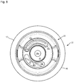
- FIG. 8 is a view, corresponding to the perspective of FIG. 7 , of the tool holder of the first embodiment having an alternative configuration of the electrical circuit implemented on a flexible and a rigid circuit substrate;
- FIG. 9 is a schematic depiction of an apparatus arrangement according to the present invention which uses at least one tool holder according to the present invention.
- Tool holder 10 encompasses a tool holder main body 12 that is referred to hereinafter simply as main body 12 .
- Main body 12 is embodied in one piece in order to achieve maximum rigidity. It is usually manufactured from metal.
- a component is also “in one piece” if it is generated using an additive method, for example from metal powder, or is assembled nondetachably from several components, for example by welding or soldering.
- Tool holder 10 which extends along a tool holder rotation axis D hereinafter referred to simply as rotation axis D, comprises at its tool-side longitudinal end 10 a a tool segment 14 , and at its oppositely located coupling-side longitudinal end 10 b a coupling segment 16 .
- Tool segment 14 encompasses a tool receiving configuration 18 in the form of a tool receiving recess.
- a shank of a tool (not depicted in FIG. 1 ) is introducible axially from tool-side longitudinal end 10 a into this tool receiving recess 18 .
- Tool segment 14 is embodied in a manner known per se as a shrink chuck, in which a shank of a tool (not depicted in FIG. 1 ) can be clamped utilizing the thermal expansion and shrinkage of the material of main body 12 .
- coupling segment 16 encompasses a coupling configuration 20 in the form of a hollow shank taper (HSK).
- HSK hollow shank taper
- tool segment 14 can also be embodied in accordance with a different clamping principle.
- coupling segment 16 can also be embodied with a different shank shape.
- a handling configuration 22 for handling tool holder 10 can be provided axially between tool segment 14 and coupling segment 16 .
- Handling configuration 22 can encompass a gripper channel 24 proceeding in a circumferential direction around rotation axis D.
- a central recess 26 passes axially completely through main body 12 .
- Segment 26 a of central recess 26 serves, among other purposes, for the delivery of coolant through tool holder 10 to the machining location at which the tool clamped in tool holder 10 is in machining engagement with a workpiece to be machined.
- Tool holder 10 is equipped with a measurement apparatus 28 for monitoring operation of the tool holder during workpiece machining.
- measurement apparatus 28 encompasses four sensors 30 , 32 , 34 , and 36 , a signal transfer apparatus 38 , an electrical circuit 40 (indicated merely schematically), and an energy supply apparatus 42 in the form of a battery pack.
- all these measurement apparatus components 30 to 42 are located within an external contour that would also be exhibited by a tool holder 10 of identical design having no measurement apparatus 28 .
- signal transfer apparatus 38 is exposed on an outer side of main body 12 in order to facilitate signal transfer, for example via radio waves, signal transfer apparatus 38 is received in a depression recess 44 of radial projection 46 that delimits gripper channel 24 toward tool-side longitudinal end 10 a .
- This depression recess 44 was configured specifically for signal transfer apparatus 38 .
- radial projection 46 extending around rotation axis D in a circumferential direction would have the same contour to the left of rotation axis D in FIG. 1 , in mirror-image fashion with reference to rotation axis D constituting a mirror axis, as to the right of rotation axis D in FIG. 1 .
- signal transfer apparatus 38 is exposed, it is therefore also located within the contour of a tool holder 10 of identical design having no measurement apparatus 28 .
- the contour of tool holder 10 of identical design having no measurement apparatus 28 is indicated with dashed lines in the region of signal transfer apparatus 38 .
- Tool segment sensor 30 constituting a tool segment sensor is arranged in tool segment 14 radially between a wall 18 a radially externally delimiting tool receiving recess 18 and an outer wall 14 a of tool segment 14 . In an axial direction, it is located with an offset axially inward from tool-side longitudinal end 10 a of tool holder 10 into main body 12 .
- Tool segment sensor 30 can be, for example, a temperature sensor that senses the temperature of tool segment 14 of tool holder 10 and supplies a corresponding sensed signal to electrical circuit 40 . This makes it possible, for example, to monitor correct tool clamping in shrink chuck of tool segment 14 .
- Tool segment sensor 30 is received from tool-side longitudinal end 10 a in a sensor receiving recess 31 .
- Sensor receiving recess 31 can be embodied, for example, as an orifice and can extend parallel to rotation axis D of tool holder 10 .
- a further sensor 32 constituting a coolant sensor 32 can be provided in segment 26 a , provided for the passage of coolant, of central recess 26 .
- This coolant sensor 32 can monitor pressure and/or temperature and/or a flow quantity per unit time, and/or the presence of a coolant flow.
- Coolant sensor 32 is also connected in signal-transferring fashion to electrical circuit 40 by means of a connecting conductor (not depicted) in conductor conduit 50 .
- Signal transfer apparatus 38 is likewise connected in signal-transferring fashion to electrical circuit 40 by way of a connecting conductor (not depicted) in conductor conduit 52 .
- electrical circuit 40 is embodied on a flexible circuit substrate 54 that is rolled around rotation axis D and received in an annular axial recess 56 .
- Electrical conductor paths and electrical functional elements are arranged on circuit substrate 54 in a manner known per se.
- Circuit substrate 54 can additionally be secured in position in annular axial recess 56 by adhesive bonding.
- axial recess 56 can be detachably closed off, preferably at its one axial longitudinal end, by a cover 58 , for example a threaded cover 58 .
- the components received in axial recess 56 therefore remain easily accessible and replaceable.
- axial recess 56 can be encapsulated with an encapsulation compound. The same also applies to the conductor conduits that are embodied in tool holder 10 or in main body 12 .
- Axial recess 56 is preferably embodied in the manner of a blind hole and is delimited exclusively, with the exception of the conductor conduits proceeding from and opening into it, by material of main body 12 and by cover 58 .
- Sensors 34 and 36 can be received in the annular axial recess 56 and connected in signal-transferring fashion to electrical circuit 40 .
- one sensor 34 can be arranged on a radially external delimiting wall, and a further sensor 36 on a radially internal delimiting wall.
- Sensors 34 and 36 can be, for example, acceleration sensors and/or can be deformation sensors, which sense, at their respective attachment location, an acceleration and/or a deformation of main body 12 that supports them. Vibrations and imbalances of tool holder 10 , as well as forces and moments acting on tool holder 10 from the machining side, can thereby be sensed.
- the sensed signals supplied from sensors 30 to 36 either can be further processed by electrical circuit 40 , or can be transferred as raw data via signal transfer apparatus 38 to a receiving device, provided outside tool holder 10 , of an evaluation apparatus attached thereto.
- FIG. 1 What is depicted as an energy supply in the example shown in FIG. 1 is a battery pack 42 that is coupled to electrical circuit 40 by way of an energy supply conductor (not depicted) passed through conductor conduit 60 .
- Conductor conduits 48 , 50 , and 52 that have already been recited serve not only for signal transfer but also for energy transfer between signal transfer apparatus 38 and sensors 30 to 34 , and electrical circuit 40 and battery pack 42 .
- Battery pack 42 is received in radial recess 62 extending radially inward from outer side 22 a of handling configuration 22 orthogonally to rotation axis D, specifically in order to avoid short circuits between battery pack 42 and the electrically conductive main body 12 made of metal, with interposition of an insulating configuration 64 separating battery pack 42 from main body 12 .
- Radial recess 62 can again be closed off, preferably detachably closed, for example again by way of a threaded cover 66 , in order to protect battery pack 42 and secure it in position.
- a flange 68 of radial projection 46 which flange separates signal transfer apparatus 38 from gripper channel 24 , is present between signal transfer apparatus 38 and the axially adjacent gripper channel 24 .
- Flange 68 like radial projection 46 as a whole, serves to flank gripper channel 24 toward tool-side longitudinal end 10 a of tool holder 10 .
- Flange 68 thus shields signal transfer apparatus 38 from external influence by a gripper during handling of tool holder 10 by the gripper.
- the contour of gripper channel 24 along the periphery remains substantially undisrupted.
- FIG. 2 depicts a second exemplifying embodiment of a tool holder according to the present invention. Identical and functionally identical components and component segments are labeled with the same reference characters as for the first embodiment depicted in FIG. 1 , but incremented by 100. The second embodiment is explained below only insofar as it differs from the first embodiment in FIG. 1 , the description of which should otherwise also be referred to for an explanation of the second embodiment.
- Tool holder 110 depicted in FIG. 2 comprises as tool receiving configuration 118 a hydraulic expansion chuck in which the unobstructed width of the tool receiving recess formed by tool receiving configuration 118 can be modified by admitting a hydraulic fluid into pressure chambers 170 .
- tool segment sensor 130 is embodied as a pressure sensor that is provided in order to sense the clamping pressure in pressure chambers 170 .
- a sensing region of tool segment sensor 130 can constitute, for that purpose, part of the wall of pressure chamber 170 .
- central recess 126 does not penetrate through main body 112 , although central recess 126 could also be embodied so as to penetrate through main body 112 in a longitudinal direction.
- Coupling segment 116 of tool holder 110 is embodied with a configuration for a spherical clamping system.
- main body 112 of the second embodiment can have subdivisions.
- wall 118 a that radially externally delimits tool receiving recess 118 can be embodied on a separate insertion component that, when combined with main body 112 , forms pressure chambers 170 .
- FIG. 3 depicts a third exemplifying embodiment of a tool holder according to the present invention. Identical and functionally identical components and component segments are labeled with the same reference characters as for the first embodiment depicted in FIG. 1 , but incremented by 200. The third embodiment is explained below only insofar as it differs from the first embodiment in FIG. 1 , the description of which should otherwise also be referred to for an explanation of the third embodiment.
- Tool holder 210 of FIG. 3 comprises a tool segment 214 that is embodied to receive a cutting head.
- Tool segment 214 comprises for that purpose a tool receiving configuration 218 in the form of a tool receiving stem having a receiving recess and an internal thread.
- Coupling segment 216 comprises a coupling configuration 220 in the form of a steep taper or SK.
- axial recess 256 for receiving electrical circuit 240 on flexible circuit substrate 254 is left open toward coupling-side longitudinal end 210 b .
- a detachable cover for closing off axial recess 256 can be provided here as well, however.
- tool holder 210 of FIG. 3 also comprises an energy supply apparatus. As in the embodiments shown previously, this can be a battery pack or a rechargeable battery pack. It can also encompass an induction coil for inductive transfer of electrical energy.
- Tool segment sensor 230 can be, for example, an acceleration sensor, so that any vibrations of tool segment 214 of tool holder 210 can be sensed and tool wear or incorrectly selected operating parameters can be inferred therefrom.
- FIGS. 4 to 6 show tool holder 10 of the first embodiment in a variety of views.
- the tool segment which is of no interest in FIGS. 4 to 6 is depicted merely as a cylinder.
- the cylinder can be imagined as being replaced by one of the tool-side conformations of FIGS. 1 to 3 .
- FIG. 4 is an elevation view of coupling segment 16 and of handling segment 22 of tool holder 10 in an unsectioned state, the internal conformation of tool holder 10 in the aforesaid segments 16 and 22 being depicted with dashed lines and in part labeled with reference characters.
- FIG. 5 is a section view in the section plane V-V, orthogonal to tool axis D, of FIG. 4 .
- FIG. 6 is a perspective longitudinal section through tool holder 10 depicted in simplified fashion in FIGS. 4 and 6 .
- FIGS. 4 to 6 firstly show how signal transfer apparatus 38 can extend along a significant portion of the circumference of tool holder 10 .
- signal transfer apparatus 38 extends over approximately 125°, i.e. somewhat more than one-third of the total circumference of radial projection 46 or of handling configuration 22 .
- Depression 44 in which signal transfer apparatus 38 is received can extend over an even larger circumferential segment than signal transfer apparatus 38 received therein.
- depression 44 can extend between two diametrically opposite axial grooves 72 a and 72 b that play a role in the handling of tool holder 10 by a gripper.
- FIGS. 4 and 5 moreover show a further axial groove 74 that is embodied to be shorter in a circumferential direction than axial grooves 72 a and 72 b recited above.
- Axial groove 74 is used as an indexing groove 74 in the context of handling of tool holder 10 so that a defined orientation of tool holder 10 around its rotation axis D can be automatically detected.
- Axial grooves 72 a and 72 b have different dimensions in a circumferential direction. More precisely, axial groove 72 a is embodied to be shorter in a circumferential direction than axial groove 72 b located opposite it.
- conductor conduit 52 that connects axial recess 56 to depression 44 is arranged tangentially with reference to axial recess 56 .
- Undesired kinking of connecting conductors between the electrical circuit arranged in axial recess 56 and signal transfer apparatus 38 arranged in depression 44 is thereby very largely avoided.
- the tangential trajectory of conductor conduit 52 furthermore decreases the tensile force that acts on the connecting conductors upon rotation of tool holder 10 around its rotation axis D as a result of centrifugal force, since the centrifugal force is for the most part absorbed by the wall of conductor conduit 52 .
- conductor conduit 52 is rotated into the section plane containing rotation axis D.
- FIG. 5 furthermore depicts an alternative body sensor 36 ′ arranged on the radially internal delimiting wall of axial recess 56 .
- this sensor is located behind the section plane and is concealed by the component.
- Body sensor 36 ′ is mounted on a flattened area of the substantially cylindrically shaped inner wall of recess 56 , so as to ensure good contact between the sensor and the substrate.
- FIG. 7 is a bottom view of tool holder 10 of FIGS. 1 and 4 to 6 along rotation axis D. Threaded cover 58 is omitted in the interest of clarity. There is therefore a direct view into the annular axial recess 56 .
- Tool holder 10 of FIG. 7 comprises an alternative embodiment of electrical circuit 40 .
- the latter is implemented in three sub-circuits 40 a to 40 c , embodied separately from one another but connected to one another in signal-transferring fashion.
- Each sub-circuit 40 a to 40 c is embodied on a separate rigid circuit substrate 76 a , 76 , and 76 c .
- Rigid circuit substrates 76 a , 76 b , and 76 c are arranged with a distribution around rotation axis D such that an inertial axis of the overall arrangement of rigid circuit substrates 76 a , 76 b , and 76 c , having sub-circuits 40 a to 40 c embodied thereon, substantially coincides with rotation axis D. This minimizes an imbalance produced by the arrangement of rigid circuit substrates 76 a , 76 b , and 76 c.
- rigid circuit substrates 76 a , 76 b , and 76 c are arranged substantially parallel to rotation axis D and approximately equidistantly with a spacing from one another in a circumferential direction around rotation axis D.
- FIG. 8 shows a further alternative embodiment of axial recess 56 and of the electrical circuit provided therein.
- the electrical circuit is in turn implemented in a manner split between two sub-circuits 40 a and 40 b , which are arranged on separate circuit substrates and are connected to one another in signal-transferring fashion.
- Sub-circuit 40 a is embodied on a flexible circuit substrate 54
- sub-circuit 40 b is embodied on a rigid circuit substrate 76
- a separate axial sub-recess 56 a and 56 b is provided for each circuit substrate, exactly one circuit substrate being arranged in each sub-recess, namely circuit substrate 54 in sub-recess 56 a and circuit substrate 76 in sub-recess 56 b
- Sub-recesses 56 a and 56 b extend in an axial direction, and partially cylindrically around a rotation axis D and around a circumferential segment of main body 12 .
- circuit 40 a is laid into sub-recess 56 a in two-ply fashion.
- the circuit can, however, likewise be laid into sub-recess 56 a in one ply, or with more than two plies.
- sub-recess 56 a possesses at its one end an enlargement in which circuit substrate 54 can be bent with a sufficiently large bending radius.
- tool holder 10 can possess any number of sub-recesses, all of which are populated with sub-circuits all comprising a rigid circuit substrate or all comprising a flexible circuit substrate, or with a mixture of rigid and flexible circuit substrates.
- sub-recesses of axial recess 56 are preferably embodied identically and are arranged symmetrically around rotation axis D.
- sub-recesses 56 a and 56 b would be embodied with the same axial depth and the same dimension in a circumferential direction, and would be arranged diametrically opposite one another.
- Rigid circuit substrates 76 or sub-circuit substrates 76 a , 76 b , and 76 c are also preferably immobilized in their respective recesses in which they are arranged, for example by adhesive bonding.
- FIG. 9 depicts by way of example an apparatus arrangement 77 that utilizes the previously described tool holder 10 according to the present invention (and also the alternative tool holders 110 and 210 ).
- Apparatus arrangement 77 encompasses a machine tool 78 , for example a multi-axis drilling and milling machine 78 , in which tool holder 10 , having a tool 11 for material-removing machining clamped therein, is received.
- Machine tool 78 comprises in known fashion a machine controller 80 that enables control of the position and speed of the tool center point (TCP) of tool 11 .
- TCP tool center point
- Apparatus arrangement 77 furthermore encompasses a receiving device 82 that is embodied for signal transfer with signal transfer apparatus 38 .
- Receiving device 82 is preferably embodied as a transmitting/receiving device 82 for bidirectional signal transfer with signal transfer apparatus 38 .
- An evaluation apparatus 84 connected in data-transferring fashion to receiving device 82 can be provided, said apparatus processing the data received by receiving device 82 from signal transfer apparatus 38 of tool holder 10 .
- Evaluation apparatus 84 can have for that purpose a memory in which data and programs are stored.
- machine controller 80 is advantageously connected in data-transferring fashion to evaluation apparatus 84 .
- Apparatus arrangement 77 can furthermore comprise a tool storage system 86 having a tool storage system manager 88 .
- Tool storage system 86 together with tool storage system manager 88 , can be connected both to machine controller 80 and to evaluation apparatus 84 so that the data sensed by the sensors of tool holder 10 are also usable in tool storage system manager 88 .
- an equivalent replacement tool 11 ′ is made ready in tool storage system 11 and clamped in machine tool 78 in place of the worn tool 11 .
- processing of the sensed signals of the sensors can already be accomplished by the previously described electrical circuit 40 in the tool holder.
- an external evaluation apparatus 84 outside tool holder 10 on the one hand a substantially greater data processing capacity can be furnished, and on the other hand the size of electrical circuit 40 in the tool holder can be reduced.
Landscapes
- Engineering & Computer Science (AREA)
- Mechanical Engineering (AREA)
- Gripping On Spindles (AREA)
- Cutting Tools, Boring Holders, And Turrets (AREA)
- Finish Polishing, Edge Sharpening, And Grinding By Specific Grinding Devices (AREA)
- Jigs For Machine Tools (AREA)
Applications Claiming Priority (4)
| Application Number | Priority Date | Filing Date | Title |
|---|---|---|---|
| DE102015220533.9A DE102015220533A1 (de) | 2015-10-21 | 2015-10-21 | Werkzeughalter mit integrierter Sensorik |
| DE102015220533.9 | 2015-10-21 | ||
| DE102015220533 | 2015-10-21 | ||
| PCT/EP2016/075458 WO2017068158A1 (fr) | 2015-10-21 | 2016-10-21 | Porte-outil à capteurs intégrés |
Publications (2)
| Publication Number | Publication Date |
|---|---|
| US20180311779A1 US20180311779A1 (en) | 2018-11-01 |
| US10828739B2 true US10828739B2 (en) | 2020-11-10 |
Family
ID=57208271
Family Applications (1)
| Application Number | Title | Priority Date | Filing Date |
|---|---|---|---|
| US15/770,090 Active 2036-10-30 US10828739B2 (en) | 2015-10-21 | 2016-10-21 | Tool holder with integrated sensor system |
Country Status (6)
| Country | Link |
|---|---|
| US (1) | US10828739B2 (fr) |
| EP (1) | EP3365132B1 (fr) |
| JP (1) | JP6975143B2 (fr) |
| CN (1) | CN108136511B (fr) |
| DE (1) | DE102015220533A1 (fr) |
| WO (1) | WO2017068158A1 (fr) |
Cited By (2)
| Publication number | Priority date | Publication date | Assignee | Title |
|---|---|---|---|---|
| RU214009U1 (ru) * | 2022-06-30 | 2022-10-07 | Федеральное государственное бюджетное образовательное учреждение высшего образования "Волгоградский государственный технический университет" (ВолгГТУ) | Динамометрическая оправка |
| DE102021128314A1 (de) | 2021-10-29 | 2023-05-04 | Blum-Novotest Gmbh | Rundlaufüberwachungsmodule und Rundlaufüberwachungsverfahren für ein im Betrieb zu rotierendes Werkzeug |
Families Citing this family (33)
| Publication number | Priority date | Publication date | Assignee | Title |
|---|---|---|---|---|
| DE102017114536B3 (de) | 2017-02-07 | 2018-07-05 | Schunk Gmbh & Co. Kg Spann- Und Greiftechnik | Verfahren und Vorrichtung zum Betätigen einer Hydro-Dehnspanneinrichtung |
| DE102017117059A1 (de) * | 2017-07-26 | 2019-01-31 | Franz Haimer Maschinenbau Kg | Werkzeugmaschinensystem mit automatischer wuchtprotokollverwertung |
| DE102018109880A1 (de) * | 2017-12-22 | 2019-06-27 | Friedrich Bleicher | Sensormodul, Maschinen- oder Werkzeugelement und Werkzeugmaschine |
| WO2019122375A1 (fr) * | 2017-12-22 | 2019-06-27 | Friedrich Bleicher | Module de détection, élément de machine ou d'outil et machine-outil |
| PL3578952T3 (pl) | 2018-06-05 | 2022-03-21 | Klaus Schlageter | Urządzenie do odsysania cząstek w narzędziu ze zintegrowanymi czujnikami |
| CN108646810B (zh) * | 2018-06-11 | 2019-11-29 | 北京航空航天大学 | 一种异质材料切削区域温度控制装置 |
| WO2020031766A1 (fr) | 2018-08-09 | 2020-02-13 | 東レ株式会社 | Procédé de fabrication d'un préimprégné, dispositif de revêtement, et appareil de fabrication d'un préimprégné |
| DE102019102788A1 (de) * | 2018-08-16 | 2020-02-20 | Schaeffler Technologies AG & Co. KG | Spannsystem für eine Schleifmaschine |
| DE102019104007A1 (de) * | 2019-02-18 | 2020-08-20 | Gühring KG | Werkzeugaufnahme mit Freiraum, Konfigurator für die Werkzeugaufnahme sowie Verfahren zum Herstellen der Werkzeugaufnahme |
| CN110244654A (zh) * | 2019-04-29 | 2019-09-17 | 福建省嘉泰智能装备有限公司 | 一种传感器监测机床加工过程各种情形有效加工段标示方法 |
| CN110091215A (zh) * | 2019-05-08 | 2019-08-06 | 北京理工大学 | 一种实时监测铣削力、振动的无线传输智能刀柄检测系统 |
| DE102019112629A1 (de) | 2019-05-14 | 2020-11-19 | Schunk Gmbh & Co. Kg Spann- Und Greiftechnik | Spanneinrichtung zum Spannen eines Bauteils, insbesondere zum Fixieren eines Werkzeugs an einer Werkzeugmaschine |
| DE102019117940A1 (de) * | 2019-07-03 | 2021-01-07 | Sycotec Gmbh & Co. Kg | Werkzeughalter |
| JPWO2021015239A1 (fr) * | 2019-07-25 | 2021-01-28 | ||
| JP6948025B2 (ja) * | 2019-08-09 | 2021-10-13 | 住友電気工業株式会社 | 切削工具、切削工具用ホルダ、工具システム、通信方法および旋削用工具 |
| US20220281019A1 (en) * | 2019-08-09 | 2022-09-08 | Sumitomo Electric Industries, Ltd. | Rotating tool, module, cutting system, processing method, and processing program |
| US20220266348A1 (en) * | 2019-08-09 | 2022-08-25 | Sumitomo Electric Industries, Ltd. | Cutting tool, cutting tool holder, tool system, and communication method |
| WO2021152831A1 (fr) * | 2020-01-31 | 2021-08-05 | 住友電気工業株式会社 | Outil de coupe, système d'outil et procédé de transmission d'informations de coupe |
| DE102020203967A1 (de) | 2020-03-26 | 2021-09-30 | MTU Aero Engines AG | Vorrichtung zur Bearbeitung eines Bauteils |
| CN111618357B (zh) * | 2020-04-21 | 2022-12-16 | 深圳精匠云创科技有限公司 | 无线数据采集装置及具有该装置的钢轨铣刀设备 |
| US20230205166A1 (en) * | 2020-06-08 | 2023-06-29 | Sumitomo Electric Industries, Ltd. | Cutting tool, tool system and communication control method |
| DE102020208529A1 (de) | 2020-07-08 | 2022-01-13 | Gühring KG | Werkzeughalter und werkzeugmaschine |
| JP7443213B2 (ja) | 2020-09-28 | 2024-03-05 | 株式会社日立製作所 | 工具状態検知システム |
| DE102021126179A1 (de) | 2020-10-08 | 2022-04-14 | Friedrich Bleicher | Sensorsystem, Maschinen- oder Werkzeugelement und Werkzeugmaschine |
| DE102020127509A1 (de) * | 2020-10-19 | 2022-04-21 | Haimer Gmbh | Werkzeughalter mit Messvorrichtung |
| DE102020127510A1 (de) | 2020-10-19 | 2022-04-21 | Haimer Gmbh | Zustandsüberwachung bei einem Werkzeughalter mit Messvorrichtung |
| DE102021104634A1 (de) | 2021-02-26 | 2022-09-01 | Röhm Gmbh | Spannvorrichtung sowie Futterflansch |
| CN113043072A (zh) * | 2021-03-22 | 2021-06-29 | 曲阜师范大学 | 一种刀具工作状态监测装置 |
| EP4134198A1 (fr) * | 2021-08-13 | 2023-02-15 | Kistler Holding AG | Système d'usinage par enlèvement des copeaux d'une pièce et de mesure et d'évaluation de la force et du couple lors de l'usinage par enlèvement des copeaux de la pièce |
| DE102021124968A1 (de) | 2021-09-27 | 2023-03-30 | INNIRION GmbH | Messeinheit und Messsystem |
| DE102021124907A1 (de) | 2021-09-27 | 2023-03-30 | Schunk Gmbh & Co. Kg Spann- Und Greiftechnik | Spanneinrichtung, Sensormodul und Sensoranordnung |
| CN115780846A (zh) * | 2022-11-28 | 2023-03-14 | 山东大学 | 一种多射流方式内冷夹具及加工机床 |
| CN116079087B (zh) * | 2023-04-12 | 2023-06-30 | 哈尔滨商业大学 | 一种智能制造的数控车床 |
Citations (15)
| Publication number | Priority date | Publication date | Assignee | Title |
|---|---|---|---|---|
| US4890306A (en) | 1987-03-30 | 1989-12-26 | Toyoda Machine Works, Ltd. | Tool holder for monitoring tool service time |
| DE9014037U1 (fr) | 1990-10-09 | 1990-12-20 | Emuge-Werk Richard Glimpel Fabrik Fuer Praezisionswerkzeuge, 8560 Lauf, De | |
| JPH03111117A (ja) | 1989-09-25 | 1991-05-10 | Kenji Machida | 無線発信機内蔵型工具ホルダー |
| JPH06114688A (ja) | 1992-09-30 | 1994-04-26 | Mazda Motor Corp | 工具のトルク検出装置 |
| EP1025952A1 (fr) | 1997-02-14 | 2000-08-09 | NT Engineering Kabushiki Kaisha | Machine d'usinage et procede de communication associe |
| DE10029953A1 (de) | 2000-06-26 | 2002-01-17 | Mapal Fab Praezision | Werkzeughalter für Werkzeugmaschinen |
| WO2005063437A1 (fr) | 2003-12-23 | 2005-07-14 | Franz Haimer Maschinenbau Kg | Porte-outil à corps actionneurs électrostrictifs destinés à influencer le comportement de concentricité du porte-outil |
| US20070059117A1 (en) | 2005-09-09 | 2007-03-15 | Haimer Gmbh | Tool holder for the shrink-attachment of tools |
| DE102006030834A1 (de) | 2006-07-04 | 2008-01-10 | ARTIS Gesellschaft für angewandte Meßtechnik mbH | Sensorsystem für Werkzeugmaschinen |
| CN201108970Y (zh) | 2007-11-23 | 2008-09-03 | 刘晓明 | 一种液压膨胀式刀具夹具 |
| US20090234490A1 (en) | 2008-03-17 | 2009-09-17 | Suprock Christopher A | Smart Machining System and Smart Tool Holder Therefor |
| EP2103379A1 (fr) | 2008-03-19 | 2009-09-23 | MTU Aero Engines GmbH | Système de mesure de force intégré au mandrin |
| US20100242696A1 (en) | 2006-06-28 | 2010-09-30 | Teeness Asa | Container Adapted to be Inserted in a Tool Holder, A Tool Holder and a System |
| CN102430960A (zh) | 2011-11-07 | 2012-05-02 | 吉林大学 | 机械手拉刀力及插刀力的测量及记录装置 |
| US20150050097A1 (en) | 2013-08-14 | 2015-02-19 | Franz Haimer Maschinenbau Kg | Tool Arrangement and Tool Receptacle for Such a Tool Arrangement |
Family Cites Families (6)
| Publication number | Priority date | Publication date | Assignee | Title |
|---|---|---|---|---|
| US63437A (en) * | 1867-04-02 | Samuel solomons | ||
| JPH0246348B2 (ja) * | 1982-10-21 | 1990-10-15 | Yotaro Hatamura | Koguhorudaagatakenshutsusochi |
| GB8503355D0 (en) * | 1985-02-09 | 1985-03-13 | Renishaw Plc | Sensing surface of object |
| JP5089342B2 (ja) * | 2007-11-07 | 2012-12-05 | セイコーインスツル株式会社 | 検出装置及びプレートの加工方法 |
| DE602008004087D1 (de) * | 2008-02-26 | 2011-02-03 | Comau Spa | Bearbeitungseinheit mit einer Regelungsvorrichtung zum Einstellen des Werkzeuges und eine drahtlose Steuerung für die Regelungsvorrichtung |
| DE102013105830A1 (de) * | 2013-06-06 | 2014-12-11 | Bilz Werkzeugfabrik Gmbh & Co. Kg | Werkzeugspannsystem |
-
2015
- 2015-10-21 DE DE102015220533.9A patent/DE102015220533A1/de active Pending
-
2016
- 2016-10-21 JP JP2018520603A patent/JP6975143B2/ja active Active
- 2016-10-21 WO PCT/EP2016/075458 patent/WO2017068158A1/fr active Application Filing
- 2016-10-21 CN CN201680061390.0A patent/CN108136511B/zh active Active
- 2016-10-21 EP EP16787791.9A patent/EP3365132B1/fr active Active
- 2016-10-21 US US15/770,090 patent/US10828739B2/en active Active
Patent Citations (25)
| Publication number | Priority date | Publication date | Assignee | Title |
|---|---|---|---|---|
| US4890306A (en) | 1987-03-30 | 1989-12-26 | Toyoda Machine Works, Ltd. | Tool holder for monitoring tool service time |
| JPH03111117A (ja) | 1989-09-25 | 1991-05-10 | Kenji Machida | 無線発信機内蔵型工具ホルダー |
| DE9014037U1 (fr) | 1990-10-09 | 1990-12-20 | Emuge-Werk Richard Glimpel Fabrik Fuer Praezisionswerkzeuge, 8560 Lauf, De | |
| JPH06114688A (ja) | 1992-09-30 | 1994-04-26 | Mazda Motor Corp | 工具のトルク検出装置 |
| EP1025952A1 (fr) | 1997-02-14 | 2000-08-09 | NT Engineering Kabushiki Kaisha | Machine d'usinage et procede de communication associe |
| US6424821B1 (en) * | 1997-02-14 | 2002-07-23 | Nt Engineering Kabushiki Kaisha | Working machine and its communication method |
| DE10029953A1 (de) | 2000-06-26 | 2002-01-17 | Mapal Fab Praezision | Werkzeughalter für Werkzeugmaschinen |
| WO2005063437A1 (fr) | 2003-12-23 | 2005-07-14 | Franz Haimer Maschinenbau Kg | Porte-outil à corps actionneurs électrostrictifs destinés à influencer le comportement de concentricité du porte-outil |
| CN101272877A (zh) | 2005-09-09 | 2008-09-24 | 海默有限公司 | 用于通过热套夹紧刀具的刀夹 |
| US8821085B2 (en) | 2005-09-09 | 2014-09-02 | Haimer Gmbh | Tool holder for clamping tools by shrink fit |
| US20090033043A1 (en) | 2005-09-09 | 2009-02-05 | Franz Haimer | Tool holder for clamping tools by shrink fit |
| US20070059117A1 (en) | 2005-09-09 | 2007-03-15 | Haimer Gmbh | Tool holder for the shrink-attachment of tools |
| US20100242696A1 (en) | 2006-06-28 | 2010-09-30 | Teeness Asa | Container Adapted to be Inserted in a Tool Holder, A Tool Holder and a System |
| DE102006030834A1 (de) | 2006-07-04 | 2008-01-10 | ARTIS Gesellschaft für angewandte Meßtechnik mbH | Sensorsystem für Werkzeugmaschinen |
| US7710287B2 (en) * | 2006-07-04 | 2010-05-04 | Artis Gesellschaft Fur Angewandte Messtechnik Mbh | Sensor system for machine tools |
| US20080030355A1 (en) | 2006-07-04 | 2008-02-07 | Dirk Lange | Sensor system for machine tools |
| CN201108970Y (zh) | 2007-11-23 | 2008-09-03 | 刘晓明 | 一种液压膨胀式刀具夹具 |
| US20090234490A1 (en) | 2008-03-17 | 2009-09-17 | Suprock Christopher A | Smart Machining System and Smart Tool Holder Therefor |
| CN102015203A (zh) | 2008-03-17 | 2011-04-13 | 克里斯托弗·A·苏普罗克 | 智能机加工系统及其智能刀具夹具 |
| EP2103379A1 (fr) | 2008-03-19 | 2009-09-23 | MTU Aero Engines GmbH | Système de mesure de force intégré au mandrin |
| US20090235763A1 (en) | 2008-03-19 | 2009-09-24 | Mtu Aero Engines Gmbh | Chuck-integrated force-measuring system |
| CN102430960A (zh) | 2011-11-07 | 2012-05-02 | 吉林大学 | 机械手拉刀力及插刀力的测量及记录装置 |
| US20150050097A1 (en) | 2013-08-14 | 2015-02-19 | Franz Haimer Maschinenbau Kg | Tool Arrangement and Tool Receptacle for Such a Tool Arrangement |
| CN104368850A (zh) | 2013-08-14 | 2015-02-25 | 弗兰茨海莫机械制造两合公司 | 刀具装置和用于这种刀具装置的刀架 |
| US9533393B2 (en) | 2013-08-14 | 2017-01-03 | Franz Haimer Maschinenbau Kg | Tool arrangement and tool receptacle for such a tool arrangement |
Non-Patent Citations (4)
| Title |
|---|
| International Search Report issued in PCT/EP2016/075458. |
| Jahresbericht 2014, Institute für Produktionsmanagement, Technologie und Werkzeugmaschinen. |
| Search Report issued in DE 10 2015 220 533.9. |
| Ziegltrum, et al., "Smart Tool = Intelligente Werkzeuge für die vernetzte Fertigung von morgen", Fachkilliquium Produktionsautomatisierung Spanender Prozesse, Feb. 10, 2015. |
Cited By (8)
| Publication number | Priority date | Publication date | Assignee | Title |
|---|---|---|---|---|
| DE102021128314A1 (de) | 2021-10-29 | 2023-05-04 | Blum-Novotest Gmbh | Rundlaufüberwachungsmodule und Rundlaufüberwachungsverfahren für ein im Betrieb zu rotierendes Werkzeug |
| WO2023072995A1 (fr) | 2021-10-29 | 2023-05-04 | Blum-Novotest Gmbh | Modules de surveillance de centrage et procédé de surveillance de centrage pour un outil devant tourner pendant son fonctionnement |
| RU214009U1 (ru) * | 2022-06-30 | 2022-10-07 | Федеральное государственное бюджетное образовательное учреждение высшего образования "Волгоградский государственный технический университет" (ВолгГТУ) | Динамометрическая оправка |
| RU214154U1 (ru) * | 2022-06-30 | 2022-10-13 | Федеральное государственное бюджетное образовательное учреждение высшего образования "Волгоградский государственный технический университет" (ВолгГТУ) | Динамометрическая оправка |
| RU214155U1 (ru) * | 2022-06-30 | 2022-10-13 | Федеральное государственное бюджетное образовательное учреждение высшего образования "Волгоградский государственный технический университет" (ВолгГТУ) | Динамометрическая оправка |
| RU214153U1 (ru) * | 2022-06-30 | 2022-10-13 | Федеральное государственное бюджетное образовательное учреждение высшего образования "Волгоградский государственный технический университет" (ВолгГТУ) | Динамометрическая оправка |
| RU214152U1 (ru) * | 2022-06-30 | 2022-10-13 | Федеральное государственное бюджетное образовательное учреждение высшего образования "Волгоградский государственный технический университет" (ВолгГТУ) | Динамометрическая оправка |
| RU215025U1 (ru) * | 2022-06-30 | 2022-11-24 | Федеральное государственное бюджетное образовательное учреждение высшего образования "Волгоградский государственный технический университет" (ВолгГТУ) | Динамометрическая оправка |
Also Published As
| Publication number | Publication date |
|---|---|
| US20180311779A1 (en) | 2018-11-01 |
| CN108136511A (zh) | 2018-06-08 |
| CN108136511B (zh) | 2021-03-12 |
| EP3365132A1 (fr) | 2018-08-29 |
| JP2018535105A (ja) | 2018-11-29 |
| JP6975143B2 (ja) | 2021-12-01 |
| EP3365132B1 (fr) | 2024-02-28 |
| DE102015220533A1 (de) | 2017-04-27 |
| WO2017068158A1 (fr) | 2017-04-27 |
Similar Documents
| Publication | Publication Date | Title |
|---|---|---|
| US10828739B2 (en) | Tool holder with integrated sensor system | |
| JP7036726B2 (ja) | 切削工具のためのセンサーモジュール、工具ホルダー、及び切削アッセンブリ | |
| US7878070B2 (en) | Chuck body for a chuck, chuck and method for determining a clamping force on such a chuck | |
| JP2018535105A5 (fr) | ||
| JP7198340B2 (ja) | ホルダ、切削工具、切削加工物の製造方法及びデータの収集方法 | |
| ES2795348T3 (es) | Dispositivo de husillo para el empleo en una máquina herramienta de control numérico | |
| JP2018054611A (ja) | 振動測定装置 | |
| US20200016666A1 (en) | Tool alignment device | |
| JP2019166600A (ja) | 旋削工具用ホルダ、旋削工具および旋削方法 | |
| US10967473B2 (en) | Spindle nose with measuring function | |
| EP1684938B1 (fr) | Adaptation d'une machine | |
| JP2009119555A (ja) | 工具ホルダ | |
| US20220118529A1 (en) | Tool holder with measuring apparatus | |
| JP2018051760A (ja) | 手持ち式工具に用いる無線式測定ユニット | |
| US11685009B2 (en) | Method of monitoring a condition in a tool holder with a measuring apparatus, and intelligent tool holder | |
| JP5997584B2 (ja) | 工具取付具および工具取付機構 | |
| WO2021015239A1 (fr) | Porte-outil, machine-outil et système de collecte de données | |
| TW202120227A (zh) | 液壓夾頭 | |
| Turc et al. | Modular Tooling System for Ultrasonic Assisted Cutting | |
| JPH02184240A (ja) | 回転体内の電気回路の電源装置 |
Legal Events
| Date | Code | Title | Description |
|---|---|---|---|
| FEPP | Fee payment procedure |
Free format text: ENTITY STATUS SET TO UNDISCOUNTED (ORIGINAL EVENT CODE: BIG.); ENTITY STATUS OF PATENT OWNER: LARGE ENTITY |
|
| AS | Assignment |
Owner name: HAIMER GMBH, GERMANY Free format text: ASSIGNMENT OF ASSIGNORS INTEREST;ASSIGNORS:HOFMANN, KLAUS;GROSCH, THOMAS;ABELE, EBERHARD;AND OTHERS;SIGNING DATES FROM 20180507 TO 20180806;REEL/FRAME:046949/0036 |
|
| STPP | Information on status: patent application and granting procedure in general |
Free format text: DOCKETED NEW CASE - READY FOR EXAMINATION |
|
| STPP | Information on status: patent application and granting procedure in general |
Free format text: NON FINAL ACTION MAILED |
|
| STPP | Information on status: patent application and granting procedure in general |
Free format text: RESPONSE TO NON-FINAL OFFICE ACTION ENTERED AND FORWARDED TO EXAMINER |
|
| STPP | Information on status: patent application and granting procedure in general |
Free format text: RESPONSE TO NON-FINAL OFFICE ACTION ENTERED AND FORWARDED TO EXAMINER |
|
| STPP | Information on status: patent application and granting procedure in general |
Free format text: NOTICE OF ALLOWANCE MAILED -- APPLICATION RECEIVED IN OFFICE OF PUBLICATIONS |
|
| STPP | Information on status: patent application and granting procedure in general |
Free format text: NOTICE OF ALLOWANCE MAILED -- APPLICATION RECEIVED IN OFFICE OF PUBLICATIONS |
|
| STPP | Information on status: patent application and granting procedure in general |
Free format text: PUBLICATIONS -- ISSUE FEE PAYMENT VERIFIED |
|
| STCF | Information on status: patent grant |
Free format text: PATENTED CASE |
|
| MAFP | Maintenance fee payment |
Free format text: PAYMENT OF MAINTENANCE FEE, 4TH YEAR, LARGE ENTITY (ORIGINAL EVENT CODE: M1551); ENTITY STATUS OF PATENT OWNER: LARGE ENTITY Year of fee payment: 4 |