US10827645B2 - Fan expansion card and motherboard module - Google Patents
Fan expansion card and motherboard module Download PDFInfo
- Publication number
- US10827645B2 US10827645B2 US16/519,012 US201916519012A US10827645B2 US 10827645 B2 US10827645 B2 US 10827645B2 US 201916519012 A US201916519012 A US 201916519012A US 10827645 B2 US10827645 B2 US 10827645B2
- Authority
- US
- United States
- Prior art keywords
- fan
- expansion card
- circuit board
- pci
- slot
- Prior art date
- Legal status (The legal status is an assumption and is not a legal conclusion. Google has not performed a legal analysis and makes no representation as to the accuracy of the status listed.)
- Active
Links
Images




Classifications
-
- H—ELECTRICITY
- H05—ELECTRIC TECHNIQUES NOT OTHERWISE PROVIDED FOR
- H05K—PRINTED CIRCUITS; CASINGS OR CONSTRUCTIONAL DETAILS OF ELECTRIC APPARATUS; MANUFACTURE OF ASSEMBLAGES OF ELECTRICAL COMPONENTS
- H05K7/00—Constructional details common to different types of electric apparatus
- H05K7/20—Modifications to facilitate cooling, ventilating, or heating
- H05K7/20009—Modifications to facilitate cooling, ventilating, or heating using a gaseous coolant in electronic enclosures
- H05K7/20136—Forced ventilation, e.g. by fans
- H05K7/20145—Means for directing air flow, e.g. ducts, deflectors, plenum or guides
-
- G—PHYSICS
- G06—COMPUTING OR CALCULATING; COUNTING
- G06F—ELECTRIC DIGITAL DATA PROCESSING
- G06F1/00—Details not covered by groups G06F3/00 - G06F13/00 and G06F21/00
- G06F1/16—Constructional details or arrangements
- G06F1/18—Packaging or power distribution
- G06F1/183—Internal mounting support structures, e.g. for supporting printed circuit boards
- G06F1/185—Mounting of expansion boards
-
- G—PHYSICS
- G06—COMPUTING OR CALCULATING; COUNTING
- G06F—ELECTRIC DIGITAL DATA PROCESSING
- G06F1/00—Details not covered by groups G06F3/00 - G06F13/00 and G06F21/00
- G06F1/16—Constructional details or arrangements
- G06F1/18—Packaging or power distribution
- G06F1/183—Internal mounting support structures, e.g. for supporting printed circuit boards
- G06F1/184—Mounting of motherboards
-
- G—PHYSICS
- G06—COMPUTING OR CALCULATING; COUNTING
- G06F—ELECTRIC DIGITAL DATA PROCESSING
- G06F1/00—Details not covered by groups G06F3/00 - G06F13/00 and G06F21/00
- G06F1/16—Constructional details or arrangements
- G06F1/18—Packaging or power distribution
- G06F1/183—Internal mounting support structures, e.g. for supporting printed circuit boards
- G06F1/185—Mounting of expansion boards
- G06F1/186—Securing of expansion boards in correspondence to slots provided at the computer enclosure
-
- G—PHYSICS
- G06—COMPUTING OR CALCULATING; COUNTING
- G06F—ELECTRIC DIGITAL DATA PROCESSING
- G06F1/00—Details not covered by groups G06F3/00 - G06F13/00 and G06F21/00
- G06F1/16—Constructional details or arrangements
- G06F1/20—Cooling means
-
- G—PHYSICS
- G06—COMPUTING OR CALCULATING; COUNTING
- G06F—ELECTRIC DIGITAL DATA PROCESSING
- G06F1/00—Details not covered by groups G06F3/00 - G06F13/00 and G06F21/00
- G06F1/16—Constructional details or arrangements
- G06F1/20—Cooling means
- G06F1/206—Cooling means comprising thermal management
-
- H—ELECTRICITY
- H05—ELECTRIC TECHNIQUES NOT OTHERWISE PROVIDED FOR
- H05K—PRINTED CIRCUITS; CASINGS OR CONSTRUCTIONAL DETAILS OF ELECTRIC APPARATUS; MANUFACTURE OF ASSEMBLAGES OF ELECTRICAL COMPONENTS
- H05K7/00—Constructional details common to different types of electric apparatus
- H05K7/20—Modifications to facilitate cooling, ventilating, or heating
-
- H—ELECTRICITY
- H05—ELECTRIC TECHNIQUES NOT OTHERWISE PROVIDED FOR
- H05K—PRINTED CIRCUITS; CASINGS OR CONSTRUCTIONAL DETAILS OF ELECTRIC APPARATUS; MANUFACTURE OF ASSEMBLAGES OF ELECTRICAL COMPONENTS
- H05K7/00—Constructional details common to different types of electric apparatus
- H05K7/20—Modifications to facilitate cooling, ventilating, or heating
- H05K7/20009—Modifications to facilitate cooling, ventilating, or heating using a gaseous coolant in electronic enclosures
- H05K7/20136—Forced ventilation, e.g. by fans
- H05K7/20172—Fan mounting or fan specifications
-
- G—PHYSICS
- G06—COMPUTING OR CALCULATING; COUNTING
- G06F—ELECTRIC DIGITAL DATA PROCESSING
- G06F2213/00—Indexing scheme relating to interconnection of, or transfer of information or other signals between, memories, input/output devices or central processing units
- G06F2213/0026—PCI express
Definitions
- the invention relates to an expansion card and a motherboard module, and more particularly, to a fan expansion card and a motherboard module.
- the heat energy generated is significantly higher than in the past due to the continuous increase in operating speed.
- Most of the central processors and display cards in the prior art are equipped with heat-dissipating components (such as cooling fans) to reduce the temperature.
- the power source of the fans installed on the motherboard is 3 pin or 4 pin fan power supply slots on the motherboard.
- fan power supply slots are limited, and the fans are also limited by the positions of the fan power supply slots and may not be compatible with power MOSFETs and other electronic components that generate heat (for example, memory chips or the like), and accordingly the heat generated is also more likely to accumulate inside the electronic device. Therefore, in the operating process of the electronic device, how to quickly discharge the internal heat thereof to the outside has become an actively researched topic for relevant manufacturers.
- the invention provides a fan expansion card, which does not occupy the 3 pin power supply slot or 4 pin fan power supply slot on the motherboard, and has a good heat dissipation effect.
- the invention provides a motherboard module having the fan expansion card.
- a fan expansion card of the invention includes a first circuit board and at least one first fan.
- the first circuit board has at least one through-hole.
- the first circuit board includes a first connection port having a PCI-E interface.
- Each of the first fans is disposed at a position on the first circuit board corresponding to the through-hole.
- the first fan is electrically connected to the first circuit board, wherein an airflow generated by each of the first fans passes through the corresponding through-hole.
- the first connection port is a PCI-E ⁇ 1, PCI-E ⁇ 2, PCI-E ⁇ 4 or PCI-E ⁇ 8 connection port.
- an area of each of the through-holes is between 50% and 100% of a size of the corresponding first fan.
- the at least one through-hole of the first circuit board includes a plurality of through-holes
- the at least one first fan includes a plurality of first fans
- the first fans are respectively disposed at positions corresponding to the through-holes.
- the through-holes are arranged in a row, in a staggered arrangement, or in an array configuration.
- sizes of the through-holes are the same or different, and sizes of the first fans are the same or different respectively corresponding to the sizes of the configured through-holes.
- the at least one through-hole of the first circuit board includes one through-hole
- the at least one first fan includes a plurality of first fans
- an area of the through-hole is between 50% and 200% of a total size of the first fans
- the first fans are disposed at positions corresponding to the through-holes.
- the first circuit board further includes a control chip electrically connected to the first connection port and the first fan, and the control chip is adapted to control a rotating speed of the first fan.
- the first circuit board further includes an external power supply slot electrically connected to the control chip.
- the first circuit board further includes a light source control circuit electrically connected to the first connection port.
- a motherboard module of the invention includes a motherboard body, a central processor, and at least any of the fan expansion cards above.
- the motherboard body includes a central processor slot, a plurality of PCI-E slots located on one side of the central processor slot, and a plurality of transistors disposed beside the central processor slot.
- the central processor is disposed in the central processor slot.
- the at least one fan expansion card includes one fan expansion card, the fan expansion card is inserted on the PCI-E slot closest to the central processor slot, and an airflow generated by the at least one first fan of the fan expansion card is blown toward the direction of the central processor and the transistors.
- the motherboard module further includes a function expansion card.
- the function expansion card includes a second circuit board, wherein the second circuit board includes a second connection port, the second connection port has a PCI-E interface, the function expansion card is disposed on one of the PCI-E slots, and the PCI-E slot in which the function expansion card is inserted is not the PCI-E slot closest to the central processor slot.
- the at least one fan expansion card includes two fan expansion cards, the function expansion card is located between the two fan expansion cards, one of the fan expansion cards is inserted on the PCI-E slot closest to the central processor slot, an airflow generated by the at least one first fan of the fan expansion card is blown toward the direction of the central processor and the transistors, the other fan expansion card is inserted on the PCI-E slot farthest from the central processor slot, and an airflow generated by the at least one first fan of the fan expansion card is blown toward a direction of the function expansion card.
- the function expansion card includes a second fan disposed on the second circuit board, the second fan blows toward a direction of the second circuit board, and an airflow generated by the second fan flows along a surface of the second circuit board.
- the second circuit board of the function expansion card includes a front surface and a back surface opposite to each other, the second fan is disposed on the front surface, the back surface faces the fan expansion card, and an airflow driven by the first fan of the fan expansion card flows through the back surface of the second circuit board of the function expansion card.
- the first connection port of the fan expansion card of the invention is a PCI-E interface connection port, which may be inserted on the PCI-E slot of the motherboard to receive power. That is, the motherboard may power the first fan of the fan expansion card via the PCI-E slot. In this way, the fan expansion card does not need to occupy the 3 pin power supply slot or 4 pin fan power supply slot on the motherboard, such that the motherboard module has more heat dissipation options.
- the first circuit board of the fan expansion card of the invention has a through-hole, and the first fan is disposed at a position on the first circuit board corresponding to the through-hole, so that the airflow generated by the first fan may pass through the corresponding through-hole.
- the air blown by the fan expansion card may travel along the normal direction of the first circuit board.
- the fan expansion card of the invention is applied on the motherboard, if the PCI-E slot in which the fan expansion card is inserted is located beside the central processor slot and the transistors, the air blown by the fan expansion card is adapted to be blown toward the direction of the central processor and the transistors to cool the central processor and the transistors.
- the fan expansion card may not only dissipate heat from a main heat source such as a central processor, but may also dissipate heat from a secondary heat source such as a transistor to achieve a good heat dissipation effect.
- FIG. 1 is a schematic diagram of a fan expansion card in accordance with an embodiment of the invention.
- FIG. 2 is a schematic diagram of a first circuit board of the fan expansion card of FIG. 1 .
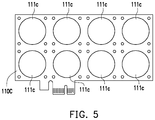
- FIG. 3 to FIG. 6 are schematic diagrams of a first circuit board of a fan expansion card in accordance with a plurality of embodiments of the invention.
- FIG. 7 is a schematic diagram of a fan expansion card adopting the first circuit board of FIG. 6 .
- FIG. 8 is a top view of the fan expansion card of FIG. 1 .
- FIG. 9 is a top view of a fan expansion card in accordance with another embodiment of the invention.
- FIG. 10 is a top view of a motherboard body of a motherboard module in accordance with an embodiment of the invention.
- FIG. 11 is a top view of the motherboard module of FIG. 10 .
- FIG. 12 is a top view of a motherboard module in accordance with another embodiment of the invention.
- FIG. 1 is a schematic diagram of a fan expansion card in accordance with an embodiment of the invention.
- FIG. 2 is a schematic diagram of a first circuit board of the fan expansion card of FIG. 1 . It is to be noted that FIG. 2 is a schematic diagram of first fans 120 removed from a first circuit board 110 in FIG. 1 , in which a control chip 113 , an external power supply slot 114 , and a light source control circuit 115 and the like are omitted to more clearly illustrate through-holes 111 on the first circuit board 110 .
- a fan expansion card 100 of the present embodiment includes the first circuit board 110 and at least one first fan 120 .
- the first circuit board 110 includes a first connection port 112 .
- the first connection port 112 is a PCI-E interface.
- the first connection port 112 is a PCI-E ⁇ 1 connection port, but in other embodiments, the first connection port 112 may also be a PCI-E ⁇ 2, PCI-E ⁇ 4, or PCI-E ⁇ 8 connection port.
- the first circuit board 110 has at least one through-hole 111 .
- the number of the through-hole 111 is, for example, two. Of course, in other embodiments, the number of the through-hole 111 may be one or more than two, and is not limited thereto.
- the at least one first fan 120 is disposed at a position on the first circuit board 110 corresponding to the at least one through-hole 111 .
- the number of the first fan 120 corresponds to the number of the through-hole 111 , for example, two.
- the two first fans 120 are respectively disposed beside the two through-holes 111 .
- the number of the first fan 120 is not limited thereto, and the number of the first fan 120 may also not correspond to the number of the through-hole 111 .
- the first fans 120 are electrically connected to the first connection port 112 of the first circuit board 110 .
- the first connection port 112 of the fan expansion card 100 is a PCI-E interface connection port that may be inserted on a PCI-E slot 214 ( FIG. 10 ) of a motherboard body 210 ( FIG. 10 ) to receive power. That is, when the fan expansion card 100 is assembled on the motherboard body 210 , the motherboard body 210 may power the first fans 120 of the fan expansion card 100 via the PCI-E slot 214 . In this way, the fan expansion card does not occupy the 3 pin fan power supply slot (not shown) or 4 pin fan power supply slot (not shown) on the motherboard body 210 .
- the first fans 120 are fixed on the first circuit board 110 by locking. More specifically, in the present embodiment, the first circuit board 110 includes a screw hole 117 . The first fans 120 are fixed on the screw hole 117 of the first circuit board 110 by a screw 116 . Of course, the manner in which the first fans 120 are fixed to the first circuit board 110 is not limited thereto. In other embodiments, the first fans 120 may also be fixed on the first circuit board 110 by other means such as snapping or bonding.
- the area of the through-holes 111 is between 50% and 100% of the size of the corresponding first fans 120 , so that most of the airflow generated by the first fans 120 may pass through the through-holes 111 .
- the airflow generated by the first fans 120 passes through the through-holes 111 from one side of the first circuit board 110 and flows through the other side of the first circuit board 110 .
- the airflow direction of the fan expansion card 100 is, for example, parallel to the normal direction of the first circuit board 110 , and may be blown toward the front or back side of the first circuit board 110 .
- the relationship between the position and number of the through-holes 111 of the first circuit board 110 , the area of the through-holes 111 , and the size of the first fans 120 is not limited thereto. Other forms of the first circuit board are described below.
- FIG. 3 to FIG. 6 are schematic diagrams of a first circuit board of a fan expansion card in accordance with a plurality of embodiments of the invention.
- FIG. 7 is a schematic diagram of a fan expansion card adopting the first circuit board of FIG. 6 .
- the main difference between a first circuit board 110 A of FIG. 3 and the first circuit board 110 of FIG. 2 is that the size of each of the through-holes 111 in FIG. 2 is the same, and the sizes of through-holes 111 a and 111 b in FIG. 3 are not the same. More specifically, the size of the through-hole 111 a is smaller than the size of the through-hole 111 b .
- the size of the fan disposed in the through-hole 111 a may also be smaller than the size of the fan disposed in the through-hole 111 b .
- the designer may first determine the number and size of the fan on the fan expansion card via the position of the heat source and the intensity of the required heat dissipation, and then determine the position and size of the through-holes on the first circuit board to obtain different forms of the first circuit boards 110 and 110 A.
- the main difference between a first circuit board 110 B of FIG. 4 and the first circuit board 110 of FIG. 2 is that the number of the through-holes 111 in FIG. 4 is three, and the positions of the through-holes 111 are in a staggered arrangement. That is to say, the number and configuration of the through-holes on the first circuit board are not limited.
- the positions of through-holes 111 of a first circuit board 110 C are arranged in an array configuration.
- the number of the through-holes 111 on the first circuit board 110 C is eight.
- the number of the through-holes 111 on the first circuit board 110 C is not limited thereto.
- the arrangement of the through-holes 111 on the first circuit board 110 C may also be an irregular arrangement, and is not limited to a straight line, staggered, or array arrangement.
- the size of the through-holes of the first circuit board is between 50% and 100% of the size of the fans, that is, the size of the through-holes of the first circuit board is less than or equal to the size of the fans, but the relationship between the size of the through-holes of the first circuit board and the size of the fans is not limited thereto.
- the size of a through-hole 111 d of a first circuit board 110 D may be greater than the size of the first fans 120 .
- the size of the through-hole of the first circuit board is between about 100% and 300% of the size of a single fan.
- the area of the through-hole is between 50% and 200% of the total size of the first fans.
- the number of the first fans 120 is not equal to the number of the through-hole 111 d . More specifically, two first fans 120 are disposed beside a single through-hole 111 d . The air generated by the two first fans 120 passes through the same through-hole 111 d .
- the proportion relationship between the size of the through-hole 111 d and the size of the first fans 120 is not limited thereto, and the number relationship between each of the through-hole 111 d and the configured first fans 120 is not limited thereto.
- the shape of the through-hole 111 d is a rectangle.
- the shape of the through-hole 111 d may also be an ellipse, a polygon, or any other shape.
- FIG. 8 is a top view of the fan expansion card of FIG. 1 .
- the first fans 120 are disposed at positions on one of the surfaces of the first circuit board 110 corresponding to the through-holes 111 , and the airflow generated by the first fans 120 (as indicated by the bold arrow) passes through the through-holes 111 .
- FIG. 9 is a top view of a fan expansion card in accordance with another embodiment of the invention.
- the fan expansion card of FIG. 8 is slightly different from the fan expansion card of FIG. 9 , and the difference is that, in the present embodiment, the size of the through-holes 111 of the first circuit board 110 is slightly greater than the size of first fans 120 a . Therefore, the first fans 120 a may be disposed inside the through-holes 111 of the first circuit board 110 . That is, at least a portion of the first fans 120 a are extended into the through-holes 111 . As such, the fan expansion card may have a smaller thickness.
- the first circuit board 110 of the fan expansion card 100 further includes a control chip 113 electrically connected to the first connection port 112 and the first fans 120 .
- the first connection port 112 of the fan expansion card 100 may receive a signal from the motherboard body 210 and transmit the signal to the control chip 113 such that the control chip 113 may control the rotating speed of the first fans 120 accordingly.
- the control chip 113 may adjust the rotating speed of the first fans 120 according to the performance of a central processor 220 ( FIG. 11 ) of a motherboard module 200 ( FIG. 11 ).
- the basis for the control chip 113 to adjust the rotating speed of the first fans 120 is not limited thereto.
- the first circuit board 110 further includes the external power supply slot 114 electrically connected to the control chip 113 .
- the power of the first fans 120 is mainly obtained by inserting the first connection port 112 in the PCI-E slot 214 ( FIG. 10 ) of the motherboard body 210 ( FIG. 10 ).
- the fan expansion card 100 may also obtain additional power by inserting a transmission line to the external power slot 114 and connecting the transmission line to a fan power supply slot (not shown) on the motherboard body 210 .
- the first circuit board 110 further includes the light source control circuit 115 electrically connected to the first connection port 112 .
- the light source control circuit 115 includes, for example, a controller and a light source electrically connected to the controller.
- the light source is, for example, a light-emitting diode, but the type of the light source is not limited.
- the controller of the light source control circuit 115 may control the output effect of the light source according to the signal received from the first connection port 112 .
- the controller of the light source control circuit 115 may adjust the color or brightness of the light source according to the performance of the central processor 220 ( FIG. 11 ) of the motherboard module 200 ( FIG. 11 ).
- the light source of the light source control circuit 115 may emit red light.
- the light source of the light source control circuit 115 may emit blue light.
- the light source control circuit 115 may also be electrically connected to the control chip 113 and change the color or brightness of the light source with the rotating speed of the first fans 120 . For example, when the first fans 120 operate at a high rotating speed, the light source of the light source control circuit 115 may emit red light, and when the first fans 120 operate at a low rotating speed, the light source of the light source control circuit 115 may emit blue light.
- FIG. 10 is a top view of a motherboard body of a motherboard module in accordance with an embodiment of the invention.
- FIG. 11 is a top view of the motherboard module of FIG. 10 .
- the motherboard body 210 includes a central processor slot 212 , a plurality of PCI-E slots 214 located on one side of the central processor slot 212 , and a plurality of transistors 216 and a plurality of memory slots 218 disposed beside the central processor slot 212 .
- the central processor slot 212 and the memory slots 218 may be respectively inserted by the central processor 220 and memory modules (not shown). Therefore, the positions where the central processor slot 212 and the memory slots 218 are located are the positions of the heat sources.
- the transistors 216 also generate heat during operation. Therefore, when the motherboard module 200 ( FIG. 11 ) is in operation, the side of the PCI-E slots 214 on the motherboard body 210 (e.g., the region in the top side of FIG. 10 ) needs to be heavily dissipated.
- the transistors 216 are, for example, power MOSFETs, but the type of the transistors 216 is not limited thereto.
- the motherboard module 200 includes a function expansion card 230
- the function expansion card 230 is, for example, a display card, but is not limited thereto.
- the function expansion card 230 also generates a large amount of heat due to a high load during operation.
- the function expansion card 230 further includes a second fan 236 disposed on a second circuit board 232 .
- the air blown by the second fan 236 flows along the surface of the second circuit board 232 to dissipate heat from the second circuit board 232 of the function expansion card 230 and exits toward the left in FIG. 11 .
- the function expansion card 230 includes a second circuit board 232 .
- the second circuit board 232 includes, for example, a PCI-E ⁇ 8 or PCI-E ⁇ 16 connection port. As seen in FIG. 11 , the function expansion card 230 is disposed on the PCI-E slot 214 that is second closest to the central processor slot 212 .
- the type of the PCI-E slots includes PCI-E ⁇ 1, PCI-E ⁇ 2, PCI-E ⁇ 4, PCI-E ⁇ 8, or PCI-E ⁇ 16 slots
- the type of the PCI-E slots on the motherboard body varies depending on the need.
- the PCI-E slot closest to or farthest from the central processor slot is a PCI-E ⁇ 1, PCI-E ⁇ 2, or PCI-E ⁇ 4 slot.
- a function expansion card such as a display card on a PCI-E slot
- a function expansion card such as a display card is usually inserted on the PCI-E ⁇ 8 or PCI-E ⁇ 16 slot due to a large operating load
- the PCI-E ⁇ 8 or PCI-E ⁇ 16 slot is usually the second or third PCI-E slot from the central processor slot 212 . That is, the PCI-E ⁇ 8 or PCI-E ⁇ 16 slot is not disposed in the PCI-E slot closest to or farthest from the central processor slot 212 . Therefore, the PCI-E slot on the motherboard body closest to or farthest from the central processor slot is usually idle.
- the fan expansion card 100 of the present embodiment since the PCI-E slot 214 on the motherboard body 210 closest to the central processor slot 212 is usually idle, the fan expansion card 100 is inserted onto, for example, the PCI-E slot 214 closest to the central processor slot 212 without affecting the installation of a function expansion card such as a general display card to dissipate heat from the central processor 220 located in the central processor slot 212 and the transistors 216 .
- a function expansion card such as a general display card to dissipate heat from the central processor 220 located in the central processor slot 212 and the transistors 216 .
- the central processor 220 of the motherboard module 200 is disposed on the central processor slot 212 of the motherboard body 210
- the fan expansion card 100 is disposed on one of the PCI-E slots 214 , such as on the PCI-E slot 214 closest to the central processor slot 212 .
- the first fans 120 of the fan expansion card 100 are, for example, direct blow fans.
- the airflow generated by the first fans 120 passes through the corresponding through-hole 111 and is adapted to be blown toward the direction of the central processor 220 and the transistors 216 , and may even be blown toward the direction of the memory modules on the memory slots 218 to dissipate heat from the main heat source (the central processor 220 ) and the secondary heat sources (the transistors 216 and the memory modules) of the motherboard module 200 .
- the second circuit board 232 of the function expansion card 230 includes a front surface 233 and a back surface 234 opposite to each other.
- the second fan 236 is disposed on the front surface 233 , and the back surface 234 faces the fan expansion card 100 .
- the airflow driven by the first fans 120 of the fan expansion card 100 flows through the back surface of the second circuit board 232 of the function expansion card 230 to dissipate heat from the function expansion card 230 .
- the airflow driven by the first fans 120 may flow from the back to the front, which may not only dissipate heat from the central processor 220 and the transistors 216 in the front, but airflow in the back may also flow along the back surface 234 of the second circuit board 232 of the function expansion card 230 to simultaneously dissipate heat from the function expansion card 230 , so that the heat dissipation effect is faster.
- FIG. 12 is a top view of a motherboard module in accordance with another embodiment of the invention.
- a motherboard module 200 A is slightly different from the motherboard module 200 . The difference is that the motherboard module 200 A includes two fan expansion cards 100 .
- One of the fan expansion cards 100 is inserted on the PCI-E slot 214 closest to the central processor slot 212 .
- the airflow generated by the first fans 120 of the fan expansion card 100 may be blown toward the direction of the central processor 220 , the transistors 216 , and the memory modules on the memory slots 218 via the corresponding through-hole 111 to dissipate heat from the memory modules on the central processor 220 , the transistors 216 , and the memory slots 218 .
- the other fan expansion card 100 is inserted on the PCI-E slot 214 farthest from the central processor slot 212 , and the airflow generated by the first fans 120 of the fan expansion card 100 passes through the corresponding through-hole 111 and is blown toward the direction of the function expansion card 230 . That is to say, the air generated by the fan expansion card 100 inserted on the PCI-E slot 214 farthest from the central processor slot 212 may be blown toward the direction of the function expansion card 230 in a concentrated manner to further enhance the heat dissipation of the function expansion card 230 .
- the fan expansion cards 100 are disposed on the PCI-E slots 214 closest to and/or farthest from the central processor slot 212 , in other embodiments, the fan expansion cards 100 may also be disposed on other PCI-E slots 214 , and may also dissipate heat from the heat source in the motherboard module.
- the first connection port of the fan expansion card of the invention is a PCI-E interface connection port, which may be inserted on the PCI-E slot of the motherboard to receive power. That is, the motherboard may power the first fan of the fan expansion card via the PCI-E slot. In this way, the fan expansion card does not need to occupy the 3 pin fan power supply slot or 4 pin fan power supply slot on the motherboard, such that the motherboard module has more heat dissipation options.
- the first circuit board of the fan expansion card of the invention has a through-hole, and the first fan is disposed at a position on the first circuit board corresponding to the through-hole, so that the airflow generated by the first fan may pass through the corresponding through-hole.
- the air blown by the fan expansion card may travel along the normal direction of the first circuit board.
- the fan expansion card of the invention is applied on the motherboard, if the PCI-E slot in which the fan expansion card is inserted is located beside the central processor slot and the transistors, the air blown by the fan expansion card is adapted to be blown toward the direction of the central processor and the transistors to cool the central processor and the transistors.
- the fan expansion card may not only dissipate heat from a main heat source such as a central processor, but may also dissipate heat from a secondary heat source such as a transistor to achieve good heat dissipation effect.
Landscapes
- Engineering & Computer Science (AREA)
- Theoretical Computer Science (AREA)
- Physics & Mathematics (AREA)
- General Engineering & Computer Science (AREA)
- Human Computer Interaction (AREA)
- General Physics & Mathematics (AREA)
- Computer Hardware Design (AREA)
- Power Engineering (AREA)
- Microelectronics & Electronic Packaging (AREA)
- Thermal Sciences (AREA)
- Cooling Or The Like Of Electrical Apparatus (AREA)
- Cooling Or The Like Of Semiconductors Or Solid State Devices (AREA)
Applications Claiming Priority (3)
| Application Number | Priority Date | Filing Date | Title |
|---|---|---|---|
| TW107127965A TWI693749B (zh) | 2018-08-10 | 2018-08-10 | 風扇擴充卡及主機板模組 |
| TW107127965A | 2018-08-10 | ||
| TW107127965 | 2018-08-10 |
Publications (2)
| Publication Number | Publication Date |
|---|---|
| US20200053910A1 US20200053910A1 (en) | 2020-02-13 |
| US10827645B2 true US10827645B2 (en) | 2020-11-03 |
Family
ID=67551280
Family Applications (1)
| Application Number | Title | Priority Date | Filing Date |
|---|---|---|---|
| US16/519,012 Active US10827645B2 (en) | 2018-08-10 | 2019-07-23 | Fan expansion card and motherboard module |
Country Status (5)
| Country | Link |
|---|---|
| US (1) | US10827645B2 (de) |
| EP (1) | EP3608752B1 (de) |
| JP (1) | JP2020027940A (de) |
| KR (1) | KR102263912B1 (de) |
| TW (1) | TWI693749B (de) |
Cited By (1)
| Publication number | Priority date | Publication date | Assignee | Title |
|---|---|---|---|---|
| US12289866B2 (en) * | 2022-04-11 | 2025-04-29 | Acer Incorporated | Graphics card and computer host |
Families Citing this family (11)
| Publication number | Priority date | Publication date | Assignee | Title |
|---|---|---|---|---|
| US11762437B2 (en) * | 2019-12-13 | 2023-09-19 | Hewlett Packard Enterprise Development Lp | Expansion fan device with adjustable fan |
| CN113495763B (zh) * | 2020-04-03 | 2024-03-19 | 神讯电脑(昆山)有限公司 | 开机方法及电子装置 |
| CN111897699A (zh) * | 2020-08-31 | 2020-11-06 | 江苏杰瑞信息科技有限公司 | 飞腾服务器的智能监控接口 |
| CN114189976A (zh) * | 2020-09-14 | 2022-03-15 | 技嘉科技股份有限公司 | 电子装置 |
| CN113286422A (zh) * | 2021-05-24 | 2021-08-20 | 英业达科技有限公司 | 主板 |
| CN114756101A (zh) * | 2022-04-29 | 2022-07-15 | 浪潮(山东)计算机科技有限公司 | 一种扩展卡散热模块及机箱 |
| CN117677133A (zh) * | 2022-08-25 | 2024-03-08 | 中兴通讯股份有限公司 | 风扇插箱、风扇框及插箱系统 |
| TWI854597B (zh) * | 2023-04-14 | 2024-09-01 | 華碩電腦股份有限公司 | 擴充卡組件、電路板組件及電子裝置 |
| CN116382442B (zh) * | 2023-04-25 | 2024-01-09 | 广东银昌科技股份有限公司 | 服务器pci槽位强力散热装置 |
| CN119712616A (zh) * | 2023-09-27 | 2025-03-28 | 亚浩电子五金塑胶(惠州)有限公司 | 风扇装置及风扇框组件 |
| CN121070143A (zh) * | 2025-10-30 | 2025-12-05 | 苏州元脑智能科技有限公司 | 服务器 |
Citations (24)
| Publication number | Priority date | Publication date | Assignee | Title |
|---|---|---|---|---|
| JPS6041096A (ja) | 1983-08-16 | 1985-03-04 | 株式会社リコー | 音声入力装置 |
| JPH062780A (ja) | 1992-06-17 | 1994-01-11 | Fujii Gokin Seisakusho:Kk | 過流出防止弁のリセット装置 |
| JPH09199881A (ja) | 1996-01-19 | 1997-07-31 | Oki Electric Ind Co Ltd | 電子機器用ファンユニット |
| TW330314B (en) | 1996-08-28 | 1998-04-21 | Siemens Ag | Method for optimizing the adhesion between extruded material and passive layer |
| TW424122B (en) | 1997-09-18 | 2001-03-01 | Bauer Spezialtiefbau | Slurry wall means |
| US6349029B1 (en) * | 1999-10-20 | 2002-02-19 | Micronpc, Llc | Computer component security apparatus and method |
| US20020097559A1 (en) * | 2000-03-31 | 2002-07-25 | Fujitsu Limited | Radiator mechanism and electronic apparatus having same |
| TW516763U (en) | 2001-10-11 | 2003-01-01 | Arbor Technology Corp | Heating device for workstation body |
| US6671177B1 (en) * | 2002-10-25 | 2003-12-30 | Evga.Com Corporation | Graphics card apparatus with improved heat dissipation |
| US20040196630A1 (en) * | 2003-04-07 | 2004-10-07 | Titan Wu | [cooling system] |
| CN2824121Y (zh) | 2005-08-16 | 2006-10-04 | 杨义 | 散热风扇卡 |
| US20070000649A1 (en) * | 2005-07-04 | 2007-01-04 | Tul Corporation | Auxiliary heat-dissipating device |
| US20070230125A1 (en) * | 2006-04-03 | 2007-10-04 | Aopen Inc. | Assembly of heat-dissipating device and circuit board |
| US7382621B2 (en) * | 2006-01-24 | 2008-06-03 | Fu Zhun Precision Industry (Shen Zhen) Co., Ltd. | Video graphics array (VGA) card assembly |
| US20090147476A1 (en) * | 2007-12-11 | 2009-06-11 | Evga Corporation | Circuit board apparatus with induced air flow for heat dissipation |
| US20100165573A1 (en) * | 2008-12-31 | 2010-07-01 | Yuan-Cheng Fang | Heat sink used in interface card |
| TWM385729U (en) | 2010-01-18 | 2010-08-01 | Hon Hai Prec Ind Co Ltd | Electronic device enclosure |
| CN201662760U (zh) | 2009-04-03 | 2010-12-01 | 扎尔曼技术株式会社 | 显卡冷却装置 |
| US20120087088A1 (en) * | 2008-08-05 | 2012-04-12 | Pipeline Micro, Inc. | Microscale heat transfer systems |
| US20120300386A1 (en) * | 2011-05-27 | 2012-11-29 | Asustek Computer Inc. | Expansion card |
| TW201325418A (zh) | 2011-12-05 | 2013-06-16 | Hon Hai Prec Ind Co Ltd | 電子裝置 |
| US20130265713A1 (en) * | 2012-04-05 | 2013-10-10 | Robert Lee Crane | Daughterboard having airflow path |
| US9986632B2 (en) * | 2016-02-24 | 2018-05-29 | Cooler Master Co., Ltd. | Water cooling system |
| CN207571657U (zh) | 2017-05-27 | 2018-07-03 | 西安微电子技术研究所 | 一种基于cpci板卡结构的双向并联智能风机模块 |
Family Cites Families (4)
| Publication number | Priority date | Publication date | Assignee | Title |
|---|---|---|---|---|
| JPS6041096U (ja) * | 1983-08-26 | 1985-03-23 | 富士通株式会社 | ファン・ユニット |
| JP2574234Y2 (ja) * | 1992-06-03 | 1998-06-11 | 富士通株式会社 | ファンユニット |
| US7486519B2 (en) * | 2006-02-24 | 2009-02-03 | Nvidia Corporation | System for cooling a heat-generating electronic device with increased air flow |
| TWI424122B (zh) * | 2011-06-15 | 2014-01-21 | Adlink Technology Inc | Electronic system Replaceable USB fan module |
-
2018
- 2018-08-10 TW TW107127965A patent/TWI693749B/zh active
-
2019
- 2019-07-23 US US16/519,012 patent/US10827645B2/en active Active
- 2019-08-06 JP JP2019144259A patent/JP2020027940A/ja active Pending
- 2019-08-07 EP EP19190501.7A patent/EP3608752B1/de active Active
- 2019-08-09 KR KR1020190097363A patent/KR102263912B1/ko active Active
Patent Citations (24)
| Publication number | Priority date | Publication date | Assignee | Title |
|---|---|---|---|---|
| JPS6041096A (ja) | 1983-08-16 | 1985-03-04 | 株式会社リコー | 音声入力装置 |
| JPH062780A (ja) | 1992-06-17 | 1994-01-11 | Fujii Gokin Seisakusho:Kk | 過流出防止弁のリセット装置 |
| JPH09199881A (ja) | 1996-01-19 | 1997-07-31 | Oki Electric Ind Co Ltd | 電子機器用ファンユニット |
| TW330314B (en) | 1996-08-28 | 1998-04-21 | Siemens Ag | Method for optimizing the adhesion between extruded material and passive layer |
| TW424122B (en) | 1997-09-18 | 2001-03-01 | Bauer Spezialtiefbau | Slurry wall means |
| US6349029B1 (en) * | 1999-10-20 | 2002-02-19 | Micronpc, Llc | Computer component security apparatus and method |
| US20020097559A1 (en) * | 2000-03-31 | 2002-07-25 | Fujitsu Limited | Radiator mechanism and electronic apparatus having same |
| TW516763U (en) | 2001-10-11 | 2003-01-01 | Arbor Technology Corp | Heating device for workstation body |
| US6671177B1 (en) * | 2002-10-25 | 2003-12-30 | Evga.Com Corporation | Graphics card apparatus with improved heat dissipation |
| US20040196630A1 (en) * | 2003-04-07 | 2004-10-07 | Titan Wu | [cooling system] |
| US20070000649A1 (en) * | 2005-07-04 | 2007-01-04 | Tul Corporation | Auxiliary heat-dissipating device |
| CN2824121Y (zh) | 2005-08-16 | 2006-10-04 | 杨义 | 散热风扇卡 |
| US7382621B2 (en) * | 2006-01-24 | 2008-06-03 | Fu Zhun Precision Industry (Shen Zhen) Co., Ltd. | Video graphics array (VGA) card assembly |
| US20070230125A1 (en) * | 2006-04-03 | 2007-10-04 | Aopen Inc. | Assembly of heat-dissipating device and circuit board |
| US20090147476A1 (en) * | 2007-12-11 | 2009-06-11 | Evga Corporation | Circuit board apparatus with induced air flow for heat dissipation |
| US20120087088A1 (en) * | 2008-08-05 | 2012-04-12 | Pipeline Micro, Inc. | Microscale heat transfer systems |
| US20100165573A1 (en) * | 2008-12-31 | 2010-07-01 | Yuan-Cheng Fang | Heat sink used in interface card |
| CN201662760U (zh) | 2009-04-03 | 2010-12-01 | 扎尔曼技术株式会社 | 显卡冷却装置 |
| TWM385729U (en) | 2010-01-18 | 2010-08-01 | Hon Hai Prec Ind Co Ltd | Electronic device enclosure |
| US20120300386A1 (en) * | 2011-05-27 | 2012-11-29 | Asustek Computer Inc. | Expansion card |
| TW201325418A (zh) | 2011-12-05 | 2013-06-16 | Hon Hai Prec Ind Co Ltd | 電子裝置 |
| US20130265713A1 (en) * | 2012-04-05 | 2013-10-10 | Robert Lee Crane | Daughterboard having airflow path |
| US9986632B2 (en) * | 2016-02-24 | 2018-05-29 | Cooler Master Co., Ltd. | Water cooling system |
| CN207571657U (zh) | 2017-05-27 | 2018-07-03 | 西安微电子技术研究所 | 一种基于cpci板卡结构的双向并联智能风机模块 |
Non-Patent Citations (3)
| Title |
|---|
| "Office Action of Japan Counterpart Application", dated Jul. 14, 2020, p1-p4. |
| "Search Report of Europe Counterpart Application", dated Nov. 7, 2019, p1-p8. |
| Gadgetmix, "Anidees AI-GP-CL8 RGB Fans For Graphic Cards." retrieved on Oct. 30, 2019, Available at: http://gadgetmix.com/anidees-ai-gp-cl8-rgb-fans-for-graphic-cards/1012/. |
Cited By (1)
| Publication number | Priority date | Publication date | Assignee | Title |
|---|---|---|---|---|
| US12289866B2 (en) * | 2022-04-11 | 2025-04-29 | Acer Incorporated | Graphics card and computer host |
Also Published As
| Publication number | Publication date |
|---|---|
| KR102263912B1 (ko) | 2021-06-14 |
| JP2020027940A (ja) | 2020-02-20 |
| KR20200018342A (ko) | 2020-02-19 |
| US20200053910A1 (en) | 2020-02-13 |
| EP3608752A1 (de) | 2020-02-12 |
| TW202010189A (zh) | 2020-03-01 |
| EP3608752B1 (de) | 2021-12-22 |
| TWI693749B (zh) | 2020-05-11 |
Similar Documents
| Publication | Publication Date | Title |
|---|---|---|
| US10827645B2 (en) | Fan expansion card and motherboard module | |
| US8246171B2 (en) | Cooling device and projector using the same | |
| US7534015B2 (en) | LED lamp with a heat dissipation device | |
| US7864523B2 (en) | Cooling device for accommodated printed circuit board in a chassis | |
| US8313221B2 (en) | Illuminating system | |
| US20070047200A1 (en) | Fan cartridge assembly | |
| US20170245357A1 (en) | Water cooling system | |
| US10529649B2 (en) | Heat dissipation module | |
| US7289323B2 (en) | Wind-guiding cover | |
| CN103941530A (zh) | 投影机冷却装置 | |
| KR20040038162A (ko) | 컴퓨터 본체 | |
| US7106586B2 (en) | Computer heat dissipating system | |
| US7436667B2 (en) | Electronic device | |
| CN102548347B (zh) | 电子设备 | |
| CN110825194A (zh) | 风扇扩展卡及主机板模块 | |
| US20080024985A1 (en) | Computer casing with high heat dissipation efficiency | |
| TW201422135A (zh) | 電子裝置 | |
| US20060256520A1 (en) | Electronic device with heat dissipation module | |
| US20220141994A1 (en) | Heat dissipation device with multiple heat dissipation zones | |
| CN100447708C (zh) | 计算机散热系统及散热方法 | |
| CN203455575U (zh) | 一种投影机及其引流罩 | |
| US8845140B2 (en) | Heat sink and lamp using the same | |
| TWI418292B (zh) | 電子設備 | |
| TWI429390B (zh) | 電子設備 | |
| TWM543532U (zh) | 散熱模組 |
Legal Events
| Date | Code | Title | Description |
|---|---|---|---|
| AS | Assignment |
Owner name: GIGA-BYTE TECHNOLOGY CO.,LTD., TAIWAN Free format text: ASSIGNMENT OF ASSIGNORS INTEREST;ASSIGNORS:CHEN, HUNG-CHENG;LIAO, TSE-HSIEN;LEE, CHUN-CHIEN;AND OTHERS;REEL/FRAME:049825/0460 Effective date: 20190716 |
|
| FEPP | Fee payment procedure |
Free format text: ENTITY STATUS SET TO UNDISCOUNTED (ORIGINAL EVENT CODE: BIG.); ENTITY STATUS OF PATENT OWNER: LARGE ENTITY |
|
| STPP | Information on status: patent application and granting procedure in general |
Free format text: DOCKETED NEW CASE - READY FOR EXAMINATION |
|
| STPP | Information on status: patent application and granting procedure in general |
Free format text: NON FINAL ACTION MAILED |
|
| STPP | Information on status: patent application and granting procedure in general |
Free format text: NOTICE OF ALLOWANCE MAILED -- APPLICATION RECEIVED IN OFFICE OF PUBLICATIONS |
|
| STPP | Information on status: patent application and granting procedure in general |
Free format text: AWAITING TC RESP, ISSUE FEE PAYMENT VERIFIED |
|
| STCF | Information on status: patent grant |
Free format text: PATENTED CASE |
|
| MAFP | Maintenance fee payment |
Free format text: PAYMENT OF MAINTENANCE FEE, 4TH YEAR, LARGE ENTITY (ORIGINAL EVENT CODE: M1551); ENTITY STATUS OF PATENT OWNER: LARGE ENTITY Year of fee payment: 4 |