US10789744B2 - Method and apparatus for augmented reality display on vehicle windscreen - Google Patents
Method and apparatus for augmented reality display on vehicle windscreen Download PDFInfo
- Publication number
- US10789744B2 US10789744B2 US15/577,044 US201615577044A US10789744B2 US 10789744 B2 US10789744 B2 US 10789744B2 US 201615577044 A US201615577044 A US 201615577044A US 10789744 B2 US10789744 B2 US 10789744B2
- Authority
- US
- United States
- Prior art keywords
- vehicle
- operator
- windscreen
- location
- determining
- Prior art date
- Legal status (The legal status is an assumption and is not a legal conclusion. Google has not performed a legal analysis and makes no representation as to the accuracy of the status listed.)
- Active
Links
- 238000000034 method Methods 0.000 title claims abstract description 14
- 230000003190 augmentative effect Effects 0.000 title abstract description 31
- 230000007613 environmental effect Effects 0.000 claims abstract description 31
- 238000004590 computer program Methods 0.000 claims description 10
- 238000012986 modification Methods 0.000 claims description 7
- 230000004048 modification Effects 0.000 claims description 7
- 238000001514 detection method Methods 0.000 description 32
- 238000009412 basement excavation Methods 0.000 description 9
- 238000010276 construction Methods 0.000 description 7
- 230000001133 acceleration Effects 0.000 description 5
- 238000004891 communication Methods 0.000 description 2
- 238000010586 diagram Methods 0.000 description 2
- 230000003287 optical effect Effects 0.000 description 2
- 244000309464 bull Species 0.000 description 1
- 210000003128 head Anatomy 0.000 description 1
- 230000010354 integration Effects 0.000 description 1
- 230000003993 interaction Effects 0.000 description 1
- 238000005259 measurement Methods 0.000 description 1
- 238000012544 monitoring process Methods 0.000 description 1
- 238000010899 nucleation Methods 0.000 description 1
- 230000002093 peripheral effect Effects 0.000 description 1
- 238000005507 spraying Methods 0.000 description 1
Images


Classifications
-
- B—PERFORMING OPERATIONS; TRANSPORTING
- B60—VEHICLES IN GENERAL
- B60W—CONJOINT CONTROL OF VEHICLE SUB-UNITS OF DIFFERENT TYPE OR DIFFERENT FUNCTION; CONTROL SYSTEMS SPECIALLY ADAPTED FOR HYBRID VEHICLES; ROAD VEHICLE DRIVE CONTROL SYSTEMS FOR PURPOSES NOT RELATED TO THE CONTROL OF A PARTICULAR SUB-UNIT
- B60W50/00—Details of control systems for road vehicle drive control not related to the control of a particular sub-unit, e.g. process diagnostic or vehicle driver interfaces
- B60W50/08—Interaction between the driver and the control system
- B60W50/14—Means for informing the driver, warning the driver or prompting a driver intervention
-
- G—PHYSICS
- G06—COMPUTING; CALCULATING OR COUNTING
- G06T—IMAGE DATA PROCESSING OR GENERATION, IN GENERAL
- G06T11/00—2D [Two Dimensional] image generation
- G06T11/60—Editing figures and text; Combining figures or text
-
- G—PHYSICS
- G02—OPTICS
- G02B—OPTICAL ELEMENTS, SYSTEMS OR APPARATUS
- G02B27/00—Optical systems or apparatus not provided for by any of the groups G02B1/00 - G02B26/00, G02B30/00
- G02B27/0093—Optical systems or apparatus not provided for by any of the groups G02B1/00 - G02B26/00, G02B30/00 with means for monitoring data relating to the user, e.g. head-tracking, eye-tracking
-
- B—PERFORMING OPERATIONS; TRANSPORTING
- B60—VEHICLES IN GENERAL
- B60K—ARRANGEMENT OR MOUNTING OF PROPULSION UNITS OR OF TRANSMISSIONS IN VEHICLES; ARRANGEMENT OR MOUNTING OF PLURAL DIVERSE PRIME-MOVERS IN VEHICLES; AUXILIARY DRIVES FOR VEHICLES; INSTRUMENTATION OR DASHBOARDS FOR VEHICLES; ARRANGEMENTS IN CONNECTION WITH COOLING, AIR INTAKE, GAS EXHAUST OR FUEL SUPPLY OF PROPULSION UNITS IN VEHICLES
- B60K35/00—Instruments specially adapted for vehicles; Arrangement of instruments in or on vehicles
- B60K35/20—Output arrangements, i.e. from vehicle to user, associated with vehicle functions or specially adapted therefor
- B60K35/21—Output arrangements, i.e. from vehicle to user, associated with vehicle functions or specially adapted therefor using visual output, e.g. blinking lights or matrix displays
- B60K35/213—Virtual instruments
-
- B—PERFORMING OPERATIONS; TRANSPORTING
- B60—VEHICLES IN GENERAL
- B60K—ARRANGEMENT OR MOUNTING OF PROPULSION UNITS OR OF TRANSMISSIONS IN VEHICLES; ARRANGEMENT OR MOUNTING OF PLURAL DIVERSE PRIME-MOVERS IN VEHICLES; AUXILIARY DRIVES FOR VEHICLES; INSTRUMENTATION OR DASHBOARDS FOR VEHICLES; ARRANGEMENTS IN CONNECTION WITH COOLING, AIR INTAKE, GAS EXHAUST OR FUEL SUPPLY OF PROPULSION UNITS IN VEHICLES
- B60K35/00—Instruments specially adapted for vehicles; Arrangement of instruments in or on vehicles
- B60K35/20—Output arrangements, i.e. from vehicle to user, associated with vehicle functions or specially adapted therefor
- B60K35/28—Output arrangements, i.e. from vehicle to user, associated with vehicle functions or specially adapted therefor characterised by the type of the output information, e.g. video entertainment or vehicle dynamics information; characterised by the purpose of the output information, e.g. for attracting the attention of the driver
-
- B—PERFORMING OPERATIONS; TRANSPORTING
- B60—VEHICLES IN GENERAL
- B60K—ARRANGEMENT OR MOUNTING OF PROPULSION UNITS OR OF TRANSMISSIONS IN VEHICLES; ARRANGEMENT OR MOUNTING OF PLURAL DIVERSE PRIME-MOVERS IN VEHICLES; AUXILIARY DRIVES FOR VEHICLES; INSTRUMENTATION OR DASHBOARDS FOR VEHICLES; ARRANGEMENTS IN CONNECTION WITH COOLING, AIR INTAKE, GAS EXHAUST OR FUEL SUPPLY OF PROPULSION UNITS IN VEHICLES
- B60K35/00—Instruments specially adapted for vehicles; Arrangement of instruments in or on vehicles
- B60K35/20—Output arrangements, i.e. from vehicle to user, associated with vehicle functions or specially adapted therefor
- B60K35/29—Instruments characterised by the way in which information is handled, e.g. showing information on plural displays or prioritising information according to driving conditions
-
- B—PERFORMING OPERATIONS; TRANSPORTING
- B60—VEHICLES IN GENERAL
- B60K—ARRANGEMENT OR MOUNTING OF PROPULSION UNITS OR OF TRANSMISSIONS IN VEHICLES; ARRANGEMENT OR MOUNTING OF PLURAL DIVERSE PRIME-MOVERS IN VEHICLES; AUXILIARY DRIVES FOR VEHICLES; INSTRUMENTATION OR DASHBOARDS FOR VEHICLES; ARRANGEMENTS IN CONNECTION WITH COOLING, AIR INTAKE, GAS EXHAUST OR FUEL SUPPLY OF PROPULSION UNITS IN VEHICLES
- B60K35/00—Instruments specially adapted for vehicles; Arrangement of instruments in or on vehicles
- B60K35/80—Arrangements for controlling instruments
- B60K35/81—Arrangements for controlling instruments for controlling displays
-
- B—PERFORMING OPERATIONS; TRANSPORTING
- B60—VEHICLES IN GENERAL
- B60W—CONJOINT CONTROL OF VEHICLE SUB-UNITS OF DIFFERENT TYPE OR DIFFERENT FUNCTION; CONTROL SYSTEMS SPECIALLY ADAPTED FOR HYBRID VEHICLES; ROAD VEHICLE DRIVE CONTROL SYSTEMS FOR PURPOSES NOT RELATED TO THE CONTROL OF A PARTICULAR SUB-UNIT
- B60W40/00—Estimation or calculation of non-directly measurable driving parameters for road vehicle drive control systems not related to the control of a particular sub unit, e.g. by using mathematical models
- B60W40/02—Estimation or calculation of non-directly measurable driving parameters for road vehicle drive control systems not related to the control of a particular sub unit, e.g. by using mathematical models related to ambient conditions
-
- B—PERFORMING OPERATIONS; TRANSPORTING
- B60—VEHICLES IN GENERAL
- B60W—CONJOINT CONTROL OF VEHICLE SUB-UNITS OF DIFFERENT TYPE OR DIFFERENT FUNCTION; CONTROL SYSTEMS SPECIALLY ADAPTED FOR HYBRID VEHICLES; ROAD VEHICLE DRIVE CONTROL SYSTEMS FOR PURPOSES NOT RELATED TO THE CONTROL OF A PARTICULAR SUB-UNIT
- B60W40/00—Estimation or calculation of non-directly measurable driving parameters for road vehicle drive control systems not related to the control of a particular sub unit, e.g. by using mathematical models
- B60W40/08—Estimation or calculation of non-directly measurable driving parameters for road vehicle drive control systems not related to the control of a particular sub unit, e.g. by using mathematical models related to drivers or passengers
-
- B—PERFORMING OPERATIONS; TRANSPORTING
- B60—VEHICLES IN GENERAL
- B60W—CONJOINT CONTROL OF VEHICLE SUB-UNITS OF DIFFERENT TYPE OR DIFFERENT FUNCTION; CONTROL SYSTEMS SPECIALLY ADAPTED FOR HYBRID VEHICLES; ROAD VEHICLE DRIVE CONTROL SYSTEMS FOR PURPOSES NOT RELATED TO THE CONTROL OF A PARTICULAR SUB-UNIT
- B60W40/00—Estimation or calculation of non-directly measurable driving parameters for road vehicle drive control systems not related to the control of a particular sub unit, e.g. by using mathematical models
- B60W40/10—Estimation or calculation of non-directly measurable driving parameters for road vehicle drive control systems not related to the control of a particular sub unit, e.g. by using mathematical models related to vehicle motion
-
- G—PHYSICS
- G02—OPTICS
- G02B—OPTICAL ELEMENTS, SYSTEMS OR APPARATUS
- G02B27/00—Optical systems or apparatus not provided for by any of the groups G02B1/00 - G02B26/00, G02B30/00
- G02B27/01—Head-up displays
-
- G—PHYSICS
- G02—OPTICS
- G02B—OPTICAL ELEMENTS, SYSTEMS OR APPARATUS
- G02B27/00—Optical systems or apparatus not provided for by any of the groups G02B1/00 - G02B26/00, G02B30/00
- G02B27/01—Head-up displays
- G02B27/0101—Head-up displays characterised by optical features
-
- G—PHYSICS
- G02—OPTICS
- G02B—OPTICAL ELEMENTS, SYSTEMS OR APPARATUS
- G02B27/00—Optical systems or apparatus not provided for by any of the groups G02B1/00 - G02B26/00, G02B30/00
- G02B27/01—Head-up displays
- G02B27/0179—Display position adjusting means not related to the information to be displayed
-
- G—PHYSICS
- G06—COMPUTING; CALCULATING OR COUNTING
- G06F—ELECTRIC DIGITAL DATA PROCESSING
- G06F3/00—Input arrangements for transferring data to be processed into a form capable of being handled by the computer; Output arrangements for transferring data from processing unit to output unit, e.g. interface arrangements
- G06F3/01—Input arrangements or combined input and output arrangements for interaction between user and computer
- G06F3/011—Arrangements for interaction with the human body, e.g. for user immersion in virtual reality
- G06F3/013—Eye tracking input arrangements
-
- G—PHYSICS
- G06—COMPUTING; CALCULATING OR COUNTING
- G06T—IMAGE DATA PROCESSING OR GENERATION, IN GENERAL
- G06T19/00—Manipulating 3D models or images for computer graphics
- G06T19/006—Mixed reality
-
- B—PERFORMING OPERATIONS; TRANSPORTING
- B60—VEHICLES IN GENERAL
- B60K—ARRANGEMENT OR MOUNTING OF PROPULSION UNITS OR OF TRANSMISSIONS IN VEHICLES; ARRANGEMENT OR MOUNTING OF PLURAL DIVERSE PRIME-MOVERS IN VEHICLES; AUXILIARY DRIVES FOR VEHICLES; INSTRUMENTATION OR DASHBOARDS FOR VEHICLES; ARRANGEMENTS IN CONNECTION WITH COOLING, AIR INTAKE, GAS EXHAUST OR FUEL SUPPLY OF PROPULSION UNITS IN VEHICLES
- B60K2360/00—Indexing scheme associated with groups B60K35/00 or B60K37/00 relating to details of instruments or dashboards
- B60K2360/16—Type of output information
-
- B—PERFORMING OPERATIONS; TRANSPORTING
- B60—VEHICLES IN GENERAL
- B60K—ARRANGEMENT OR MOUNTING OF PROPULSION UNITS OR OF TRANSMISSIONS IN VEHICLES; ARRANGEMENT OR MOUNTING OF PLURAL DIVERSE PRIME-MOVERS IN VEHICLES; AUXILIARY DRIVES FOR VEHICLES; INSTRUMENTATION OR DASHBOARDS FOR VEHICLES; ARRANGEMENTS IN CONNECTION WITH COOLING, AIR INTAKE, GAS EXHAUST OR FUEL SUPPLY OF PROPULSION UNITS IN VEHICLES
- B60K2360/00—Indexing scheme associated with groups B60K35/00 or B60K37/00 relating to details of instruments or dashboards
- B60K2360/18—Information management
-
- B—PERFORMING OPERATIONS; TRANSPORTING
- B60—VEHICLES IN GENERAL
- B60K—ARRANGEMENT OR MOUNTING OF PROPULSION UNITS OR OF TRANSMISSIONS IN VEHICLES; ARRANGEMENT OR MOUNTING OF PLURAL DIVERSE PRIME-MOVERS IN VEHICLES; AUXILIARY DRIVES FOR VEHICLES; INSTRUMENTATION OR DASHBOARDS FOR VEHICLES; ARRANGEMENTS IN CONNECTION WITH COOLING, AIR INTAKE, GAS EXHAUST OR FUEL SUPPLY OF PROPULSION UNITS IN VEHICLES
- B60K2360/00—Indexing scheme associated with groups B60K35/00 or B60K37/00 relating to details of instruments or dashboards
- B60K2360/20—Optical features of instruments
- B60K2360/33—Illumination features
- B60K2360/334—Projection means
-
- B60K2370/155—
-
- B60K2370/16—
-
- B60K2370/18—
-
- B60K2370/334—
-
- B60K2370/52—
-
- B—PERFORMING OPERATIONS; TRANSPORTING
- B60—VEHICLES IN GENERAL
- B60W—CONJOINT CONTROL OF VEHICLE SUB-UNITS OF DIFFERENT TYPE OR DIFFERENT FUNCTION; CONTROL SYSTEMS SPECIALLY ADAPTED FOR HYBRID VEHICLES; ROAD VEHICLE DRIVE CONTROL SYSTEMS FOR PURPOSES NOT RELATED TO THE CONTROL OF A PARTICULAR SUB-UNIT
- B60W50/00—Details of control systems for road vehicle drive control not related to the control of a particular sub-unit, e.g. process diagnostic or vehicle driver interfaces
- B60W50/08—Interaction between the driver and the control system
- B60W50/14—Means for informing the driver, warning the driver or prompting a driver intervention
- B60W2050/146—Display means
-
- B—PERFORMING OPERATIONS; TRANSPORTING
- B60—VEHICLES IN GENERAL
- B60W—CONJOINT CONTROL OF VEHICLE SUB-UNITS OF DIFFERENT TYPE OR DIFFERENT FUNCTION; CONTROL SYSTEMS SPECIALLY ADAPTED FOR HYBRID VEHICLES; ROAD VEHICLE DRIVE CONTROL SYSTEMS FOR PURPOSES NOT RELATED TO THE CONTROL OF A PARTICULAR SUB-UNIT
- B60W2300/00—Indexing codes relating to the type of vehicle
- B60W2300/17—Construction vehicles, e.g. graders, excavators
-
- B—PERFORMING OPERATIONS; TRANSPORTING
- B60—VEHICLES IN GENERAL
- B60Y—INDEXING SCHEME RELATING TO ASPECTS CROSS-CUTTING VEHICLE TECHNOLOGY
- B60Y2400/00—Special features of vehicle units
- B60Y2400/92—Driver displays
-
- E—FIXED CONSTRUCTIONS
- E02—HYDRAULIC ENGINEERING; FOUNDATIONS; SOIL SHIFTING
- E02F—DREDGING; SOIL-SHIFTING
- E02F3/00—Dredgers; Soil-shifting machines
-
- E—FIXED CONSTRUCTIONS
- E02—HYDRAULIC ENGINEERING; FOUNDATIONS; SOIL SHIFTING
- E02F—DREDGING; SOIL-SHIFTING
- E02F9/00—Component parts of dredgers or soil-shifting machines, not restricted to one of the kinds covered by groups E02F3/00 - E02F7/00
- E02F9/26—Indicating devices
- E02F9/261—Surveying the work-site to be treated
-
- G—PHYSICS
- G02—OPTICS
- G02B—OPTICAL ELEMENTS, SYSTEMS OR APPARATUS
- G02B27/00—Optical systems or apparatus not provided for by any of the groups G02B1/00 - G02B26/00, G02B30/00
- G02B27/01—Head-up displays
- G02B27/0101—Head-up displays characterised by optical features
- G02B2027/0138—Head-up displays characterised by optical features comprising image capture systems, e.g. camera
-
- G—PHYSICS
- G02—OPTICS
- G02B—OPTICAL ELEMENTS, SYSTEMS OR APPARATUS
- G02B27/00—Optical systems or apparatus not provided for by any of the groups G02B1/00 - G02B26/00, G02B30/00
- G02B27/01—Head-up displays
- G02B27/0101—Head-up displays characterised by optical features
- G02B2027/014—Head-up displays characterised by optical features comprising information/image processing systems
-
- G—PHYSICS
- G02—OPTICS
- G02B—OPTICAL ELEMENTS, SYSTEMS OR APPARATUS
- G02B27/00—Optical systems or apparatus not provided for by any of the groups G02B1/00 - G02B26/00, G02B30/00
- G02B27/01—Head-up displays
- G02B27/0101—Head-up displays characterised by optical features
- G02B2027/0141—Head-up displays characterised by optical features characterised by the informative content of the display
-
- G—PHYSICS
- G02—OPTICS
- G02B—OPTICAL ELEMENTS, SYSTEMS OR APPARATUS
- G02B27/00—Optical systems or apparatus not provided for by any of the groups G02B1/00 - G02B26/00, G02B30/00
- G02B27/01—Head-up displays
- G02B27/0179—Display position adjusting means not related to the information to be displayed
- G02B2027/0187—Display position adjusting means not related to the information to be displayed slaved to motion of at least a part of the body of the user, e.g. head, eye
Definitions
- the present disclosure relates generally to an augmented reality (AR) display, and more particularly to an AR display for a construction vehicle windscreen.
- AR augmented reality
- Augmented reality is the integration of information with an environment perceived by a user.
- Augmented reality can be implemented using a window through which a user can view an environment.
- a projector can be used to project information onto the window.
- the information can overlay certain objects that the user can see through the window.
- the information can be displayed in an opaque, transparent, or semi-transparent manner.
- Augmented reality can be used with a vehicle to provide additional information to a user by projecting the information onto the vehicle's windscreen (also referred to as windshield).
- the vehicle's windscreen also referred to as windshield
- information about the vehicle's speed, compass heading, etc. can be projected onto the vehicles windscreen to provide the user with a heads-up display (HUD).
- HUD heads-up display
- Use of a HUD allows the operator of the vehicle to continuously view the environment through the vehicle's windscreen by allowing the user to view information on the windscreen rather than the vehicle's instrument panel.
- Augmented reality displays provide additional information to a user about vehicle parameters and existing objects that can be seen through a window on which additional information is displayed.
- a method for providing a machine operator with an augmented reality view of an environment includes determining a location and orientation of a vehicle. An eye position and gaze of an operator of the vehicle are also determined. Job information to be displayed to the operator of the vehicle is determined based on the location of the vehicle and the orientation of the vehicle. The job information is displayed to the operator based on the eye position and gaze of the operator of the vehicle. In one embodiment, environmental features that can be seen through the windscreen are determined. The identification and display of job information are further based on the determination of environmental features. In one embodiment, the determination of environmental features is based on detection of objects located in the environment in which the vehicle is located. Job information can include construction parameters, agricultural operations, and/or surface modification parameters.
- a particular job is identified by operator input and identification of job information is further based on the operator input.
- the display of job information comprises displaying an attribute image pertaining to job information overlaying an environmental feature based on the eye position and gaze of the operator. A location for the attribute image can be determined based on data from the environment awareness device.
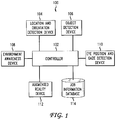
- FIG. 1 depicts a system for providing an augmented reality display to an operator of a machine
- FIG. 2 depicts a machine equipped with an augmented reality display and associated components
- FIG. 3 depicts a schematic of an augmented reality system for displaying an image to an operator of a machine
- FIG. 4 depicts examples of images displayed on an augmented reality display with and without modification to account for eye position and gaze direction;
- FIG. 5 depicts a flowchart of a method for displaying an image to an operator of a machine according to one embodiment
- FIG. 6 depicts a high-level block diagram of a computer.
- Augmented reality is used to provide an operator of a vehicle (e.g., a machine such as a construction machine) with information concerning a job to be performed and additional information.
- the operator of a vehicle is provided with a heads-up display (HUD) on a windscreen (also referred to as a windshield) of the vehicle.
- the HUD provides the operator with information concerning a job, such as surface modification, structure construction, surface construction, etc.
- the information displayed to the operator is based on a location and orientation of the machine.
- the information displayed by the HUD can be used by the machine operator to operate the machine in order to perform a job. For example, an operator can be provided with a virtual boundary of an area designated for excavation displayed on the windscreen.
- the virtual boundary of the area is displayed to the operator based on a location and gaze of the operator's eyes in order to align the real view through the windscreen with the information displayed on the windscreen. This allows the operator to view virtual information aligned with real objects and locations seen through the windscreen. If the location of the operator's eyes and the gaze of the operator are not taken into account when displaying virtual images, the virtual images may not align with real objects and locations seen through the windscreen.
- the HUD provides the operator with information about a particular area with respect to desired structures and surfaces that don't currently exist. Multiple devices are used to provide an augmented reality view to the machine operator.
- FIG. 1 depicts a system 100 for an augmented reality display on a vehicle windscreen.
- Location and orientation detection device 104 is one or more devices used to determine a location and orientation of an associated machine on which device 104 is located.
- a global navigation satellite system (GNSS) receiver can be used to determine a location of the machine.
- the GNSS receiver (also referred to as a global positioning system (GPS) receiver) can also be used to determine an orientation of the machine.
- GPS global positioning system
- GNSS data pertaining to movement of the machine in conjunction with knowledge of how the machine is capable of moving can be used to determine an orientation of the machine.
- a GNSS receiver can be used to determine a location of a machine and another device can be used to determine an orientation of the machine.
- An inertial measurement unit can be used to determine an orientation of a machine.
- An IMU can be mounted or otherwise located on the machine.
- the IMU measures acceleration of the machine in order to determine movement and an orientation of the machine. For example, if a starting orientation of a machine is known, the IMU can measure acceleration of the machine in different directions in order to determine a current orientation of the machine based on the starting orientation and acceleration of the machine in one or more directions.
- An IMU can also be used to determine a location of the machine if a starting location is known. For example, if a forward acceleration is detected by the IMU, this acceleration can be used to determine that a machine is moving forward at a particular speed. The current location of the machine can be determined based on the direction the machine is travelling and how long the machine has been travelling at the particular speed.
- a laser tracking unit, optical tracking unit, and/or stereo camera can also be used to determine a location and/or orientation of a machine.
- a combination of devices such as a GNSS receiver and an IMU, can be used to determine a location and position of a machine. Other combinations of devices can be used as well.
- Object detection device 106 is used to detect objects and obstacles in an area in which a machine is located.
- object detection device 106 includes one or more sensors for monitoring the area in which the machine is located.
- the object detection device can use any type of hardware such as a sonic transceiver, a laser transceiver, an optical sensing device (e.g., camera or stereo camera), radar transceiver, etc. Any type of sensor or device, or combination of sensors and/or devices, that can detect objects and obstacles in an area in which the machine is located can be used.
- Environment awareness device 108 is used to determine placement of additional information displayed to the user so that the information does not interfere with real objects that the operator needs to see.
- environment awareness device 108 includes an object detection device that is used to detect objects and obstacles in an area in which a machine is located.
- the object detection device of environment awareness device 108 is separate from object detection device 106 .
- the environment awareness device uses data obtained by object detection device 106 . Information pertaining to objects located in the area in which the machine is located is then used to determine placement of additional information for display to an operator of the machine so that real objects are not hidden by additional information displayed via the machine's windscreen.
- Eye position and gaze detection device 110 is used to determine a position of an operator's eyes and the direction of the operator's gaze.
- the position of the operator's eyes is determined with respect to the windscreen.
- the operator's eyes can be located centered with respect to the windscreen.
- the position of the operator's eyes changes with movement of the operator's head. For example, an operator may lean left or right, thereby changing the position of the operator's eyes with respect to the windscreen.
- the gaze of the operator is where the operator is looking. For example, the operator can be looking forward, left, right, up, or down.
- eye position and gaze direction of the operator are used to position an image projected on a windscreen of a machine so that additional information is arranged with respect to real objects that can be seen through the windscreen. For example, an image of a lead line pointing to an object can be displayed on the windscreen so that the lead line points to the object based on the eye position and gaze direction of the operator.
- eye position and gaze detection device 110 comprises a stereo camera but can comprise any device, or group of devices, capable of detecting an operator's eye position and gaze direction.
- Augmented reality device 112 is a device used to display information to a machine operator.
- augmented reality device 112 comprises a projector for projecting an image onto a windscreen of a machine in which augmented reality device 112 is located.
- Augmented reality device 112 can project an image onto a transparent film that is attached to the windscreen.
- augmented reality device 112 can adjust the luminosity and contrast of an image displayed on the windscreen in order to promote viewing of the image and visibility of the real world on the outside of the windscreen.
- the luminosity and/or contrast of the displayed image can also be adjusted to prevent discomfort of the operator. Adjustment of the luminosity and/or contrast of the image displayed can be automatic or user controlled.
- Job information database 114 is used to store information pertaining to a job that requires use of a machine.
- Job information database 114 can also store information related to an environment in which the machine is located. For example, information concerning an excavation is stored in job information database 114 along with information pertaining to the location (e.g., environment) in which the excavation to be performed.
- Job information database 114 can be accessed in order to obtain information used in generating and displaying information to a machine operator.
- Controller 102 is a processor for receiving data from various devices, accessing job information database 114 , and outputting data to augmented reality device 112 to cause an image to be displayed to an operator of an associated machine.
- controller 102 , location and orientation detection device 104 , object detection device 106 , environment awareness device 108 , eye position and gaze detection device 110 , augmented reality device 112 , and job information database 114 are physically located on a machine, such as a construction machine.
- Controller 102 can include peripherals, such as a keyboard, cursor controller (e.g., a mouse) and a display (not shown) to allow a user to interact with controller 102 .
- Controller 102 can communicate one or more of the components shown in FIG. 1 via a wired and/or wireless network.
- one or more devices can be located remote from the machine.
- job information database 114 can be located remote from controller 102 and data can be transmitted and received between the two components.
- data is transmitted between job information database 114 and controller 102 wirelessly.
- one or more components of this device can be located remote from the machine on which controller 102 is located.
- FIG. 2 depicts a machine 101 equipped with an augmented reality system and related components.
- Controller 102 eye position and gaze detection device 110 , augmented reality device 112 , and job information database 114 , in this embodiment, are shown located in a cab of machine 101 .
- Location and orientation device 104 object detection device 106 , and environment awareness device 108 , in this embodiment, are shown located on the roof of the cab of machine 101 .
- FIG. 3 depicts a schematic of an augmented reality system for displaying an image to an operator of machine 101 .
- FIG. 3 depicts windscreen 204 of machine 101 in which some components of system 100 are located.
- Operator 202 is shown located in the cab of the machine and viewing environmental feature 208 through windscreen 204 .
- Controller 102 (shown in FIGS. 1 and 2 ) is in communication with eye position and gaze detection device 110 and augmented reality device 112 . Based on data from location and orientation device 104 and object detection device 106 , controller 102 determines attribute image 212 to be displayed to operator 202 .
- attribute image 212 is determined based on information pertaining to the environment in which the machine is located and data from eye position and gaze detection device 110 , environment awareness device 108 , and job information database 114 . Data from environment awareness device 108 is used to determine placement of attribute image 212 so that it does not interfere with parts of the environment that operator 202 needs to see, such as obstacles or structures.
- attribute image 212 is displayed to operator 202 by augmented reality device 112 projecting the attribute image 212 onto windscreen 204 .
- Attribute image 212 in this example, is an arrow indicating an operation to be performed by operator 202 using the machine in which the operator is located.
- Attribute image 212 is projected onto windscreen 204 in a particular location as shown by projection lines 214 .
- the particular location of windscreen 204 on which attribute image 212 is displayed is based on an eye position and gaze of operator 202 in order to align attribute image 212 with the view operator 202 has of environmental feature 208 as shown by view lines 210 .
- the placement of attribute image 212 is determined based on information from job information database 114 using machine location and orientation information from location and orientation detection device 104 . For example, an area requiring excavation can be determined to be near the machine based on machine location. The placement of attribute image 212 can be determined based on machine orientation. If the area to be excavated is currently in view of the operator through the windscreen, attribute image 212 will be displayed based on the eye position and gaze of operator 202 . In addition, information from object detection device 106 is used to identify objects in the environment in which the machine is located. The placement of attribute image 212 can be modified based on information from environment awareness device 108 in order to prevent occlusion of objects that operator 202 needs to see.
- placement of attribute image 212 on windscreen 204 is determined using a line intersection method.
- a line extending from the operator's eye position to an object of interest (e.g., environmental feature 208 ) in the direction of the operator's gaze is calculated.
- the line comprises a plurality of points. The point along the line where the windscreen intersects the line is determined.
- the attribute image 212 is then placed (e.g., projected) on windscreen 204 aligned with the object of interest with respect to the operator's eye position by aligning the attribute image 212 with the intersection point of the line at windscreen 204 .
- a geometric center of an image of the object of interest as viewed by the operator is determined and a geometric center of attribute image 212 is located on windscreen 204 at the intersection point.
- the line can extend from a position of one of the operator's eyes or a midpoint between the operator's eyes. In one embodiment, the midpoint between the operator's eyes is determined prior to calculating the line extending from the midpoint to the object of interest.
- FIG. 4 depicts an augmented reality view when operator eye position and location are not used to modify the location of an attribute image.
- the attribute image should be displayed in the location depicted by phantom attribute image 404 , but instead is displayed in an incorrect location as shown by the location of attribute image 402 .
- the location of attribute image 402 is not adjusted to account for the operator's eye position and gaze direction.
- the location of phantom attribute image 404 is where the image would be displayed if the location of the image was modified based on the operator's eye position and gaze direction.
- FIG. 5 depicts a flow chart of method 500 performed by controller 102 for displaying information to an operator of a machine.
- user input is received by controller 102 .
- the user input identifies a particular job for which the operator would like information. For example, depending on the type of machine that the operator is using, the operator may want to see excavation information, construction information, etc.
- controller 102 determines a location of the vehicle on which controller 102 is located.
- controller 102 determines an orientation of the vehicle on which controller 102 is located. In one embodiment, location and orientation information is determined based on information received by controller 102 from location and orientation device detection device 104 .
- controller 102 determines an eye position of the operator.
- controller 102 determines a gaze of the operator. In one embodiment, the eye position and gaze of the operator are determined based on information received by controller 102 from eye position and gaze detection device 110 .
- controller 102 determines environmental features of the environment in which the vehicle is located.
- controller 102 determines environmental features using information received from object detection device 106 .
- features such as mounds, depressions, equipment, structures, etc.
- Controller 102 can use the information received pertaining to objects and compare this information to environment data contained in job information database 114 .
- environment data can be used to identify objects detected in the environment in which the vehicle is located.
- controller 102 identifies job information to be displayed to a user.
- job information is identified by controller 102 using information stored in job information database 114 .
- controller 102 can identify the environment in which the vehicle is located using the location and orientation of the vehicle. The particular job information the operator would like to view is determined using the user input from the operator.
- an operator of the machine can request and be provided with a display including a virtual boundary of the excavation area and a virtual indication of a required excavation depth.
- the operator can request and be provided with a display including a virtual boundary of the job site and a virtual cut indication and a virtual fill indication.
- a tractor operator can request and be provided with a virtual map of a seeding or spraying job.
- the job information identified in step 514 is displayed to the operator.
- the job information identified for display is transmitted from controller 102 to augmented reality device 112 which, in one embodiment, projects the information on the vehicle's windscreen.
- job information identified and displayed to the operator comprises one or more attribute images.
- each attribute image is associated with an environmental feature.
- controller 102 can assign an attribute image to an area of the environment that needs to be excavated.
- the attribute image comprises an image indicating a depth of excavation required.
- One or more attribute images can be associated with a particular environmental feature.
- the location an attribute image is displayed on the windscreen can be modified based on the environment in which the vehicle is located.
- Information about the environment is received from environment awareness device 108 .
- controller 102 can modify the display of one or more attribute images in order to prevent occlusion or obstruction of the object that should not be interacted with.
- a location of an attribute can be designated to prevent occlusion of an object.
- a luminosity and/or a transparency of an attribute image can also be adjusted to prevent obstruction of an operator's view of an object that should not be interacted with.
- Controller 102 can each be implemented using a computer.
- a high-level block diagram of such a computer is illustrated in FIG. 6 .
- Computer 602 contains a processor 604 which controls the overall operation of the computer 602 by executing computer program instructions which define such operation.
- the computer program instructions may be stored in a storage device 612 , or other computer readable medium (e.g., magnetic disk, CD ROM, etc.), and loaded into memory 610 when execution of the computer program instructions is desired.
- the computer 602 can be defined by the computer program instructions stored in the memory 610 and/or storage 612 and controlled by the processor 604 executing the computer program instructions.
- the computer program instructions can be implemented as computer executable code programmed by one skilled in the art to perform an algorithm defined by the method steps of FIG. 5 .
- the processor 604 executes an algorithm defined by the method steps of FIG. 5 .
- the computer 602 also includes one or more network interfaces 606 for communicating with other devices via a network.
- the computer 602 also includes input/output devices 608 that enable user interaction with the computer 602 (e.g., display, keyboard, mouse, speakers, buttons, etc.)
- input/output devices 608 that enable user interaction with the computer 602 (e.g., display, keyboard, mouse, speakers, buttons, etc.)
- FIG. 6 is a high level representation of some of the components of such a computer for illustrative purposes.
Landscapes
- Engineering & Computer Science (AREA)
- Physics & Mathematics (AREA)
- General Physics & Mathematics (AREA)
- Theoretical Computer Science (AREA)
- Transportation (AREA)
- Mechanical Engineering (AREA)
- General Engineering & Computer Science (AREA)
- Chemical & Material Sciences (AREA)
- Combustion & Propulsion (AREA)
- Optics & Photonics (AREA)
- Human Computer Interaction (AREA)
- Automation & Control Theory (AREA)
- Mathematical Physics (AREA)
- Computer Graphics (AREA)
- Computer Hardware Design (AREA)
- Software Systems (AREA)
- Processing Or Creating Images (AREA)
- User Interface Of Digital Computer (AREA)
- Instrument Panels (AREA)
- Transforming Electric Information Into Light Information (AREA)
Applications Claiming Priority (1)
| Application Number | Priority Date | Filing Date | Title |
|---|---|---|---|
| PCT/RU2016/000186 WO2017176143A1 (en) | 2016-04-04 | 2016-04-04 | Method and apparatus for augmented reality display on vehicle windscreen |
Publications (2)
| Publication Number | Publication Date |
|---|---|
| US20180144523A1 US20180144523A1 (en) | 2018-05-24 |
| US10789744B2 true US10789744B2 (en) | 2020-09-29 |
Family
ID=60000511
Family Applications (1)
| Application Number | Title | Priority Date | Filing Date |
|---|---|---|---|
| US15/577,044 Active US10789744B2 (en) | 2016-04-04 | 2016-04-04 | Method and apparatus for augmented reality display on vehicle windscreen |
Country Status (6)
| Country | Link |
|---|---|
| US (1) | US10789744B2 (ja) |
| EP (1) | EP3440496A4 (ja) |
| JP (1) | JP2019521403A (ja) |
| KR (1) | KR102340298B1 (ja) |
| AU (1) | AU2016402225B2 (ja) |
| WO (1) | WO2017176143A1 (ja) |
Cited By (1)
| Publication number | Priority date | Publication date | Assignee | Title |
|---|---|---|---|---|
| US11905675B2 (en) | 2019-08-05 | 2024-02-20 | Topcon Positioning Systems, Inc. | Vision-based blade positioning |
Families Citing this family (9)
| Publication number | Priority date | Publication date | Assignee | Title |
|---|---|---|---|---|
| EP3543402A1 (de) * | 2018-03-19 | 2019-09-25 | Joseph Vögele AG | Baumaschine zum erstellen oder bearbeiten einer strasse |
| US20190355177A1 (en) * | 2018-05-15 | 2019-11-21 | Honeywell International Inc. | Building system maintenance using mixed reality |
| JP7151392B2 (ja) | 2018-11-07 | 2022-10-12 | コベルコ建機株式会社 | 建設機械の遠隔操作装置 |
| JP7159903B2 (ja) * | 2019-02-19 | 2022-10-25 | コベルコ建機株式会社 | 目標位置推測装置 |
| JP7318258B2 (ja) * | 2019-03-26 | 2023-08-01 | コベルコ建機株式会社 | 遠隔操作システムおよび遠隔操作サーバ |
| EP4097552A4 (en) | 2020-01-28 | 2023-11-22 | Topcon Positioning Systems, Inc. | SYSTEM AND METHOD FOR CONTROLLING A WORK DEVICE ON A WORK MACHINE USING MACHINE VISION |
| JP7013509B2 (ja) * | 2020-03-25 | 2022-01-31 | 株式会社インフォマティクス | 建設機械における図面投影システム、図面投影方法及びプログラム |
| US20220136214A1 (en) * | 2020-11-05 | 2022-05-05 | Trimble Inc. | High-accuracy augmented reality display for construction machines |
| US20230141588A1 (en) * | 2021-11-11 | 2023-05-11 | Caterpillar Paving Products Inc. | System and method for configuring augmented reality on a worksite |
Citations (13)
| Publication number | Priority date | Publication date | Assignee | Title |
|---|---|---|---|---|
| JP2002146846A (ja) | 2000-11-13 | 2002-05-22 | Topcon Corp | 建設機械の施工案内装置 |
| WO2005024144A1 (ja) | 2003-09-02 | 2005-03-17 | Komatsu Ltd. | 施工目標指示装置 |
| WO2005121707A2 (en) | 2004-06-03 | 2005-12-22 | Making Virtual Solid, L.L.C. | En-route navigation display method and apparatus using head-up display |
| US20080262669A1 (en) * | 2006-09-22 | 2008-10-23 | Jadi, Inc. | Autonomous vehicle controller |
| US20090058678A1 (en) * | 2007-08-27 | 2009-03-05 | Mazda Motor Corporation | Driving assist device for vehicle |
| US20090091475A1 (en) | 2005-11-16 | 2009-04-09 | Aisin Seiki Kabushiki Kaisha | Parking assist device |
| JP2010018141A (ja) | 2008-07-10 | 2010-01-28 | Caterpillar Japan Ltd | 建設機械におけるディスプレイ装置 |
| US20130158778A1 (en) * | 2011-12-14 | 2013-06-20 | General Motors Llc | Method of providing information to a vehicle |
| US20140240313A1 (en) | 2009-03-19 | 2014-08-28 | Real Time Companies | Computer-aided system for 360° heads up display of safety/mission critical data |
| US20140362195A1 (en) * | 2013-03-15 | 2014-12-11 | Honda Motor, Co., Ltd. | Enhanced 3-dimensional (3-d) navigation |
| DE112013006256T5 (de) | 2012-12-28 | 2015-10-01 | Komatsu Ltd. | Baumaschinen-Anzeigesystem und Verfahren zum Steuern desselben |
| US20160004305A1 (en) | 2014-07-03 | 2016-01-07 | Topcon Positioning Systems, Inc. | Method and Apparatus for Construction Machine Visualization |
| US9794638B2 (en) * | 2013-12-27 | 2017-10-17 | Geun Sik Jo | Caption replacement service system and method for interactive service in video on demand |
Family Cites Families (4)
| Publication number | Priority date | Publication date | Assignee | Title |
|---|---|---|---|---|
| US8692739B2 (en) * | 2011-09-22 | 2014-04-08 | GM Global Technology Operations LLC | Dynamic information presentation on full windshield head-up display |
| JP2016502479A (ja) * | 2012-12-07 | 2016-01-28 | ボルボトラックコーポレーション | 車両装備、車両装備を制御する方法及びコンピュータプログラム |
| KR102004000B1 (ko) * | 2012-12-26 | 2019-07-25 | 두산인프라코어 주식회사 | 헤드업 디스플레이를 이용한 건설기계의 작업 가이드 디스플레이 장치 및 방법 |
| US9096128B2 (en) * | 2013-01-14 | 2015-08-04 | Intel Corporation | Creating a sensory experience in a vehicle |
-
2016
- 2016-04-04 AU AU2016402225A patent/AU2016402225B2/en active Active
- 2016-04-04 KR KR1020187030339A patent/KR102340298B1/ko active IP Right Grant
- 2016-04-04 US US15/577,044 patent/US10789744B2/en active Active
- 2016-04-04 JP JP2018550676A patent/JP2019521403A/ja active Pending
- 2016-04-04 EP EP16898061.3A patent/EP3440496A4/en active Pending
- 2016-04-04 WO PCT/RU2016/000186 patent/WO2017176143A1/en active Application Filing
Patent Citations (15)
| Publication number | Priority date | Publication date | Assignee | Title |
|---|---|---|---|---|
| JP2002146846A (ja) | 2000-11-13 | 2002-05-22 | Topcon Corp | 建設機械の施工案内装置 |
| WO2005024144A1 (ja) | 2003-09-02 | 2005-03-17 | Komatsu Ltd. | 施工目標指示装置 |
| US20070010925A1 (en) | 2003-09-02 | 2007-01-11 | Komatsu Ltd. | Construction target indicator device |
| WO2005121707A2 (en) | 2004-06-03 | 2005-12-22 | Making Virtual Solid, L.L.C. | En-route navigation display method and apparatus using head-up display |
| US20090091475A1 (en) | 2005-11-16 | 2009-04-09 | Aisin Seiki Kabushiki Kaisha | Parking assist device |
| US20080262669A1 (en) * | 2006-09-22 | 2008-10-23 | Jadi, Inc. | Autonomous vehicle controller |
| US20090058678A1 (en) * | 2007-08-27 | 2009-03-05 | Mazda Motor Corporation | Driving assist device for vehicle |
| JP2010018141A (ja) | 2008-07-10 | 2010-01-28 | Caterpillar Japan Ltd | 建設機械におけるディスプレイ装置 |
| US20140240313A1 (en) | 2009-03-19 | 2014-08-28 | Real Time Companies | Computer-aided system for 360° heads up display of safety/mission critical data |
| US20130158778A1 (en) * | 2011-12-14 | 2013-06-20 | General Motors Llc | Method of providing information to a vehicle |
| DE112013006256T5 (de) | 2012-12-28 | 2015-10-01 | Komatsu Ltd. | Baumaschinen-Anzeigesystem und Verfahren zum Steuern desselben |
| US20160193920A1 (en) | 2012-12-28 | 2016-07-07 | Komatsu Ltd. | Construction Machinery Display System and Control Method for Same |
| US20140362195A1 (en) * | 2013-03-15 | 2014-12-11 | Honda Motor, Co., Ltd. | Enhanced 3-dimensional (3-d) navigation |
| US9794638B2 (en) * | 2013-12-27 | 2017-10-17 | Geun Sik Jo | Caption replacement service system and method for interactive service in video on demand |
| US20160004305A1 (en) | 2014-07-03 | 2016-01-07 | Topcon Positioning Systems, Inc. | Method and Apparatus for Construction Machine Visualization |
Non-Patent Citations (3)
| Title |
|---|
| Extended Search Report dated Oct. 16, 2019, in connection with European Patent Application Serial No. 16898061.3, 10 pgs. |
| International Search Report and Written Opinion dated Jan. 26, 2017, in connection with International Patent Application No. PCT/RU2016/000186, 5 pgs. |
| Notification of Reasons of Refusal dated May 26, 2020, in connection with Japanese Patent Application No. 2018-550676, filed Apr. 4, 2018, 9 pgs (including English translation). |
Cited By (1)
| Publication number | Priority date | Publication date | Assignee | Title |
|---|---|---|---|---|
| US11905675B2 (en) | 2019-08-05 | 2024-02-20 | Topcon Positioning Systems, Inc. | Vision-based blade positioning |
Also Published As
| Publication number | Publication date |
|---|---|
| US20180144523A1 (en) | 2018-05-24 |
| KR20180133864A (ko) | 2018-12-17 |
| EP3440496A4 (en) | 2019-11-13 |
| AU2016402225B2 (en) | 2022-02-10 |
| KR102340298B1 (ko) | 2021-12-20 |
| JP2019521403A (ja) | 2019-07-25 |
| AU2016402225A1 (en) | 2018-09-13 |
| EP3440496A1 (en) | 2019-02-13 |
| WO2017176143A1 (en) | 2017-10-12 |
Similar Documents
| Publication | Publication Date | Title |
|---|---|---|
| US10789744B2 (en) | Method and apparatus for augmented reality display on vehicle windscreen | |
| US11181737B2 (en) | Head-up display device for displaying display items having movement attribute or fixed attribute, display control method, and control program | |
| EP3164787B1 (en) | Method and apparatus for construction machine visualization | |
| US10147165B2 (en) | Display device, control method, program and recording medium | |
| JP4366716B2 (ja) | 車両用情報表示装置 | |
| US20150199847A1 (en) | Head Mountable Display System | |
| US20150203036A1 (en) | Information processing device, information processing method, and non-transitory computer-readable recording medium | |
| JP6545423B2 (ja) | 調整装置、表示システム及び調整方法 | |
| US20210088352A1 (en) | Control device | |
| US11024040B2 (en) | Dynamic object tracking | |
| KR102531888B1 (ko) | 자동차에서 디스플레이 장치를 작동하기 위한 방법 | |
| CN108139224A (zh) | 车辆用显示装置 | |
| JP2016091192A (ja) | 虚像表示装置、制御方法、プログラム、及び記憶媒体 | |
| US20220326028A1 (en) | Method and system of vehicle driving assistance | |
| KR20170014451A (ko) | 시야 확보 시스템, 방법 및 이를 수행하기 위한 단말 | |
| JPWO2011135660A1 (ja) | ナビゲーション装置、ナビゲーション方法、ナビゲーションプログラムおよび記録媒体 | |
| KR20130119144A (ko) | 투명 디스플레이 패널을 이용한 객체 표시 방법 및 장치 | |
| KR20170055577A (ko) | 헤드업 디스플레이를 이용한 건물정보 표시 장치 및 방법 | |
| US20210216769A1 (en) | Providing augmented reality images to an operator of a machine | |
| JP7013509B2 (ja) | 建設機械における図面投影システム、図面投影方法及びプログラム | |
| WO2020230418A1 (ja) | 表示装置 | |
| JP2020163942A (ja) | 表示装置 | |
| JP2005201635A (ja) | 車両用ナビゲーションシステム | |
| JP2019043312A (ja) | ヘッドアップディスプレイ装置 | |
| KR20180026418A (ko) | 헤드업 디스플레이의 좌표 매칭 장치 및 그 방법 |
Legal Events
| Date | Code | Title | Description |
|---|---|---|---|
| FEPP | Fee payment procedure |
Free format text: ENTITY STATUS SET TO UNDISCOUNTED (ORIGINAL EVENT CODE: BIG.); ENTITY STATUS OF PATENT OWNER: LARGE ENTITY |
|
| AS | Assignment |
Owner name: LIMITED LIABILITY COMPANY "TOPCON POSITIONING SYSTEMS", RUSSIAN FEDERATION Free format text: ASSIGNMENT OF ASSIGNORS INTEREST;ASSIGNOR:EDELMAN, LEONID VALERIANOVICH;REEL/FRAME:046806/0034 Effective date: 20180627 Owner name: LIMITED LIABILITY COMPANY "TOPCON POSITIONING SYSTEMS", RUSSIAN FEDERATION Free format text: ASSIGNMENT OF ASSIGNORS INTEREST;ASSIGNOR:PAGLIANI, DANIELE;REEL/FRAME:046804/0631 Effective date: 20180723 Owner name: LIMITED LIABILITY COMPANY "TOPCON POSITIONING SYST Free format text: ASSIGNMENT OF ASSIGNORS INTEREST;ASSIGNOR:PAGLIANI, DANIELE;REEL/FRAME:046804/0631 Effective date: 20180723 Owner name: LIMITED LIABILITY COMPANY "TOPCON POSITIONING SYST Free format text: ASSIGNMENT OF ASSIGNORS INTEREST;ASSIGNOR:EDELMAN, LEONID VALERIANOVICH;REEL/FRAME:046806/0034 Effective date: 20180627 |
|
| STPP | Information on status: patent application and granting procedure in general |
Free format text: FINAL REJECTION MAILED |
|
| AS | Assignment |
Owner name: TOPCON POSITIONING SYSTEMS, INC., CALIFORNIA Free format text: ASSIGNMENT OF ASSIGNORS INTEREST;ASSIGNOR:LIMITED LIABILITY COMPANY "TOPCON POSITIONING SYSTEMS";REEL/FRAME:048410/0223 Effective date: 20180913 |
|
| STPP | Information on status: patent application and granting procedure in general |
Free format text: DOCKETED NEW CASE - READY FOR EXAMINATION |
|
| STPP | Information on status: patent application and granting procedure in general |
Free format text: NON FINAL ACTION MAILED |
|
| STPP | Information on status: patent application and granting procedure in general |
Free format text: RESPONSE TO NON-FINAL OFFICE ACTION ENTERED AND FORWARDED TO EXAMINER |
|
| STPP | Information on status: patent application and granting procedure in general |
Free format text: FINAL REJECTION MAILED |
|
| STPP | Information on status: patent application and granting procedure in general |
Free format text: NON FINAL ACTION MAILED |
|
| STPP | Information on status: patent application and granting procedure in general |
Free format text: RESPONSE TO NON-FINAL OFFICE ACTION ENTERED AND FORWARDED TO EXAMINER |
|
| STPP | Information on status: patent application and granting procedure in general |
Free format text: AWAITING TC RESP., ISSUE FEE NOT PAID |
|
| STPP | Information on status: patent application and granting procedure in general |
Free format text: NOTICE OF ALLOWANCE MAILED -- APPLICATION RECEIVED IN OFFICE OF PUBLICATIONS |
|
| STCF | Information on status: patent grant |
Free format text: PATENTED CASE |
|
| MAFP | Maintenance fee payment |
Free format text: PAYMENT OF MAINTENANCE FEE, 4TH YEAR, LARGE ENTITY (ORIGINAL EVENT CODE: M1551); ENTITY STATUS OF PATENT OWNER: LARGE ENTITY Year of fee payment: 4 |