US10760573B2 - Method of pumping in a system of vacuum pumps and system of vacuum pumps - Google Patents
Method of pumping in a system of vacuum pumps and system of vacuum pumps Download PDFInfo
- Publication number
- US10760573B2 US10760573B2 US15/321,839 US201415321839A US10760573B2 US 10760573 B2 US10760573 B2 US 10760573B2 US 201415321839 A US201415321839 A US 201415321839A US 10760573 B2 US10760573 B2 US 10760573B2
- Authority
- US
- United States
- Prior art keywords
- vacuum pump
- rotary vane
- main
- auxiliary
- lubricated rotary
- Prior art date
- Legal status (The legal status is an assumption and is not a legal conclusion. Google has not performed a legal analysis and makes no representation as to the accuracy of the status listed.)
- Active, expires
Links
- 238000005086 pumping Methods 0.000 title claims abstract description 33
- 238000000034 method Methods 0.000 title claims abstract description 27
- 239000007789 gas Substances 0.000 claims abstract description 44
- 238000007599 discharging Methods 0.000 claims description 2
- 230000003213 activating effect Effects 0.000 claims 2
- 230000006835 compression Effects 0.000 description 5
- 238000007906 compression Methods 0.000 description 5
- 230000004913 activation Effects 0.000 description 3
- 230000007423 decrease Effects 0.000 description 3
- 230000009471 action Effects 0.000 description 2
- 230000008901 benefit Effects 0.000 description 2
- 230000008859 change Effects 0.000 description 2
- 238000005259 measurement Methods 0.000 description 2
- 230000009467 reduction Effects 0.000 description 2
- 230000015572 biosynthetic process Effects 0.000 description 1
- 238000004364 calculation method Methods 0.000 description 1
- 210000000078 claw Anatomy 0.000 description 1
- 230000008878 coupling Effects 0.000 description 1
- 238000010168 coupling process Methods 0.000 description 1
- 238000005859 coupling reaction Methods 0.000 description 1
- 238000013523 data management Methods 0.000 description 1
- 230000001419 dependent effect Effects 0.000 description 1
- 238000011161 development Methods 0.000 description 1
- 230000018109 developmental process Effects 0.000 description 1
- 230000000694 effects Effects 0.000 description 1
- 238000005516 engineering process Methods 0.000 description 1
- 238000009434 installation Methods 0.000 description 1
- 238000012986 modification Methods 0.000 description 1
- 230000004048 modification Effects 0.000 description 1
- 230000000750 progressive effect Effects 0.000 description 1
- 230000000630 rising effect Effects 0.000 description 1
- 230000001960 triggered effect Effects 0.000 description 1
- 238000011144 upstream manufacturing Methods 0.000 description 1
Images


Classifications
-
- F—MECHANICAL ENGINEERING; LIGHTING; HEATING; WEAPONS; BLASTING
- F04—POSITIVE - DISPLACEMENT MACHINES FOR LIQUIDS; PUMPS FOR LIQUIDS OR ELASTIC FLUIDS
- F04C—ROTARY-PISTON, OR OSCILLATING-PISTON, POSITIVE-DISPLACEMENT MACHINES FOR LIQUIDS; ROTARY-PISTON, OR OSCILLATING-PISTON, POSITIVE-DISPLACEMENT PUMPS
- F04C28/00—Control of, monitoring of, or safety arrangements for, pumps or pumping installations specially adapted for elastic fluids
- F04C28/24—Control of, monitoring of, or safety arrangements for, pumps or pumping installations specially adapted for elastic fluids characterised by using valves controlling pressure or flow rate, e.g. discharge valves or unloading valves
-
- F—MECHANICAL ENGINEERING; LIGHTING; HEATING; WEAPONS; BLASTING
- F04—POSITIVE - DISPLACEMENT MACHINES FOR LIQUIDS; PUMPS FOR LIQUIDS OR ELASTIC FLUIDS
- F04C—ROTARY-PISTON, OR OSCILLATING-PISTON, POSITIVE-DISPLACEMENT MACHINES FOR LIQUIDS; ROTARY-PISTON, OR OSCILLATING-PISTON, POSITIVE-DISPLACEMENT PUMPS
- F04C2/00—Rotary-piston machines or pumps
- F04C2/30—Rotary-piston machines or pumps having the characteristics covered by two or more groups F04C2/02, F04C2/08, F04C2/22, F04C2/24 or having the characteristics covered by one of these groups together with some other type of movement between co-operating members
- F04C2/34—Rotary-piston machines or pumps having the characteristics covered by two or more groups F04C2/02, F04C2/08, F04C2/22, F04C2/24 or having the characteristics covered by one of these groups together with some other type of movement between co-operating members having the movement defined in groups F04C2/08 or F04C2/22 and relative reciprocation between the co-operating members
- F04C2/344—Rotary-piston machines or pumps having the characteristics covered by two or more groups F04C2/02, F04C2/08, F04C2/22, F04C2/24 or having the characteristics covered by one of these groups together with some other type of movement between co-operating members having the movement defined in groups F04C2/08 or F04C2/22 and relative reciprocation between the co-operating members with vanes reciprocating with respect to the inner member
-
- F—MECHANICAL ENGINEERING; LIGHTING; HEATING; WEAPONS; BLASTING
- F04—POSITIVE - DISPLACEMENT MACHINES FOR LIQUIDS; PUMPS FOR LIQUIDS OR ELASTIC FLUIDS
- F04C—ROTARY-PISTON, OR OSCILLATING-PISTON, POSITIVE-DISPLACEMENT MACHINES FOR LIQUIDS; ROTARY-PISTON, OR OSCILLATING-PISTON, POSITIVE-DISPLACEMENT PUMPS
- F04C23/00—Combinations of two or more pumps, each being of rotary-piston or oscillating-piston type, specially adapted for elastic fluids; Pumping installations specially adapted for elastic fluids; Multi-stage pumps specially adapted for elastic fluids
- F04C23/001—Combinations of two or more pumps, each being of rotary-piston or oscillating-piston type, specially adapted for elastic fluids; Pumping installations specially adapted for elastic fluids; Multi-stage pumps specially adapted for elastic fluids of similar working principle
-
- F—MECHANICAL ENGINEERING; LIGHTING; HEATING; WEAPONS; BLASTING
- F04—POSITIVE - DISPLACEMENT MACHINES FOR LIQUIDS; PUMPS FOR LIQUIDS OR ELASTIC FLUIDS
- F04C—ROTARY-PISTON, OR OSCILLATING-PISTON, POSITIVE-DISPLACEMENT MACHINES FOR LIQUIDS; ROTARY-PISTON, OR OSCILLATING-PISTON, POSITIVE-DISPLACEMENT PUMPS
- F04C18/00—Rotary-piston pumps specially adapted for elastic fluids
- F04C18/30—Rotary-piston pumps specially adapted for elastic fluids having the characteristics covered by two or more of groups F04C18/02, F04C18/08, F04C18/22, F04C18/24, F04C18/48, or having the characteristics covered by one of these groups together with some other type of movement between co-operating members
- F04C18/34—Rotary-piston pumps specially adapted for elastic fluids having the characteristics covered by two or more of groups F04C18/02, F04C18/08, F04C18/22, F04C18/24, F04C18/48, or having the characteristics covered by one of these groups together with some other type of movement between co-operating members having the movement defined in group F04C18/08 or F04C18/22 and relative reciprocation between the co-operating members
- F04C18/344—Rotary-piston pumps specially adapted for elastic fluids having the characteristics covered by two or more of groups F04C18/02, F04C18/08, F04C18/22, F04C18/24, F04C18/48, or having the characteristics covered by one of these groups together with some other type of movement between co-operating members having the movement defined in group F04C18/08 or F04C18/22 and relative reciprocation between the co-operating members with vanes reciprocating with respect to the inner member
-
- F—MECHANICAL ENGINEERING; LIGHTING; HEATING; WEAPONS; BLASTING
- F04—POSITIVE - DISPLACEMENT MACHINES FOR LIQUIDS; PUMPS FOR LIQUIDS OR ELASTIC FLUIDS
- F04C—ROTARY-PISTON, OR OSCILLATING-PISTON, POSITIVE-DISPLACEMENT MACHINES FOR LIQUIDS; ROTARY-PISTON, OR OSCILLATING-PISTON, POSITIVE-DISPLACEMENT PUMPS
- F04C25/00—Adaptations of pumps for special use of pumps for elastic fluids
- F04C25/02—Adaptations of pumps for special use of pumps for elastic fluids for producing high vacuum
-
- F—MECHANICAL ENGINEERING; LIGHTING; HEATING; WEAPONS; BLASTING
- F04—POSITIVE - DISPLACEMENT MACHINES FOR LIQUIDS; PUMPS FOR LIQUIDS OR ELASTIC FLUIDS
- F04C—ROTARY-PISTON, OR OSCILLATING-PISTON, POSITIVE-DISPLACEMENT MACHINES FOR LIQUIDS; ROTARY-PISTON, OR OSCILLATING-PISTON, POSITIVE-DISPLACEMENT PUMPS
- F04C28/00—Control of, monitoring of, or safety arrangements for, pumps or pumping installations specially adapted for elastic fluids
- F04C28/02—Control of, monitoring of, or safety arrangements for, pumps or pumping installations specially adapted for elastic fluids specially adapted for several pumps connected in series or in parallel
-
- F—MECHANICAL ENGINEERING; LIGHTING; HEATING; WEAPONS; BLASTING
- F04—POSITIVE - DISPLACEMENT MACHINES FOR LIQUIDS; PUMPS FOR LIQUIDS OR ELASTIC FLUIDS
- F04C—ROTARY-PISTON, OR OSCILLATING-PISTON, POSITIVE-DISPLACEMENT MACHINES FOR LIQUIDS; ROTARY-PISTON, OR OSCILLATING-PISTON, POSITIVE-DISPLACEMENT PUMPS
- F04C29/00—Component parts, details or accessories of pumps or pumping installations, not provided for in groups F04C18/00 - F04C28/00
- F04C29/0042—Driving elements, brakes, couplings, transmissions specially adapted for pumps
- F04C29/0085—Prime movers
-
- F—MECHANICAL ENGINEERING; LIGHTING; HEATING; WEAPONS; BLASTING
- F04—POSITIVE - DISPLACEMENT MACHINES FOR LIQUIDS; PUMPS FOR LIQUIDS OR ELASTIC FLUIDS
- F04C—ROTARY-PISTON, OR OSCILLATING-PISTON, POSITIVE-DISPLACEMENT MACHINES FOR LIQUIDS; ROTARY-PISTON, OR OSCILLATING-PISTON, POSITIVE-DISPLACEMENT PUMPS
- F04C29/00—Component parts, details or accessories of pumps or pumping installations, not provided for in groups F04C18/00 - F04C28/00
- F04C29/02—Lubrication; Lubricant separation
- F04C29/026—Lubricant separation
-
- F—MECHANICAL ENGINEERING; LIGHTING; HEATING; WEAPONS; BLASTING
- F04—POSITIVE - DISPLACEMENT MACHINES FOR LIQUIDS; PUMPS FOR LIQUIDS OR ELASTIC FLUIDS
- F04C—ROTARY-PISTON, OR OSCILLATING-PISTON, POSITIVE-DISPLACEMENT MACHINES FOR LIQUIDS; ROTARY-PISTON, OR OSCILLATING-PISTON, POSITIVE-DISPLACEMENT PUMPS
- F04C29/00—Component parts, details or accessories of pumps or pumping installations, not provided for in groups F04C18/00 - F04C28/00
- F04C29/12—Arrangements for admission or discharge of the working fluid, e.g. constructional features of the inlet or outlet
- F04C29/124—Arrangements for admission or discharge of the working fluid, e.g. constructional features of the inlet or outlet with inlet and outlet valves specially adapted for rotary or oscillating piston pumps
- F04C29/126—Arrangements for admission or discharge of the working fluid, e.g. constructional features of the inlet or outlet with inlet and outlet valves specially adapted for rotary or oscillating piston pumps of the non-return type
-
- F—MECHANICAL ENGINEERING; LIGHTING; HEATING; WEAPONS; BLASTING
- F04—POSITIVE - DISPLACEMENT MACHINES FOR LIQUIDS; PUMPS FOR LIQUIDS OR ELASTIC FLUIDS
- F04C—ROTARY-PISTON, OR OSCILLATING-PISTON, POSITIVE-DISPLACEMENT MACHINES FOR LIQUIDS; ROTARY-PISTON, OR OSCILLATING-PISTON, POSITIVE-DISPLACEMENT PUMPS
- F04C2240/00—Components
- F04C2240/30—Casings or housings
-
- F—MECHANICAL ENGINEERING; LIGHTING; HEATING; WEAPONS; BLASTING
- F04—POSITIVE - DISPLACEMENT MACHINES FOR LIQUIDS; PUMPS FOR LIQUIDS OR ELASTIC FLUIDS
- F04C—ROTARY-PISTON, OR OSCILLATING-PISTON, POSITIVE-DISPLACEMENT MACHINES FOR LIQUIDS; ROTARY-PISTON, OR OSCILLATING-PISTON, POSITIVE-DISPLACEMENT PUMPS
- F04C2240/00—Components
- F04C2240/40—Electric motor
-
- F—MECHANICAL ENGINEERING; LIGHTING; HEATING; WEAPONS; BLASTING
- F04—POSITIVE - DISPLACEMENT MACHINES FOR LIQUIDS; PUMPS FOR LIQUIDS OR ELASTIC FLUIDS
- F04C—ROTARY-PISTON, OR OSCILLATING-PISTON, POSITIVE-DISPLACEMENT MACHINES FOR LIQUIDS; ROTARY-PISTON, OR OSCILLATING-PISTON, POSITIVE-DISPLACEMENT PUMPS
- F04C2270/00—Control; Monitoring or safety arrangements
- F04C2270/18—Pressure
- F04C2270/185—Controlled or regulated
-
- F—MECHANICAL ENGINEERING; LIGHTING; HEATING; WEAPONS; BLASTING
- F04—POSITIVE - DISPLACEMENT MACHINES FOR LIQUIDS; PUMPS FOR LIQUIDS OR ELASTIC FLUIDS
- F04C—ROTARY-PISTON, OR OSCILLATING-PISTON, POSITIVE-DISPLACEMENT MACHINES FOR LIQUIDS; ROTARY-PISTON, OR OSCILLATING-PISTON, POSITIVE-DISPLACEMENT PUMPS
- F04C28/00—Control of, monitoring of, or safety arrangements for, pumps or pumping installations specially adapted for elastic fluids
- F04C28/06—Control of, monitoring of, or safety arrangements for, pumps or pumping installations specially adapted for elastic fluids specially adapted for stopping, starting, idling or no-load operation
Definitions
- the present invention relates to a pumping method making it possible to reduce the consumption of electrical energy as well as increase the performance in terms of flow rate and final vacuum in a pumping system in which the main pump is a lubricated rotary vane vacuum pump.
- the invention likewise relates to a system of vacuum pumps which can be used to achieve the method according to the present invention.
- the present invention has as object to propose a pumping method in a system of vacuum pumps making it possible to reduce the electrical energy necessary for putting a chamber under vacuum and for maintaining it, as well as to reduce the temperature of the exit gas.
- the present invention also has as object to propose a pumping method in a system of vacuum pumps making it possible to obtain a higher flow rate at low pressure than that which can be obtained with the aid of a single lubricated rotary vane vacuum pump during the pumping of a vacuum chamber.
- the present invention likewise has as object to propose a pumping method in a system of vacuum pumps making it possible to obtain a better vacuum than that which can be obtained with the aid of a single lubricated rotary vane vacuum pump during the pumping of a vacuum chamber.
- the method according to the present invention thus consists essentially of making an auxiliary lubricated rotary vane vacuum pump operate continuously all the while that the main lubricated rotary vane vacuum pump pumps the gases contained in the vacuum chamber through the gas inlet port, but also all the while that the main lubricated rotary vane vacuum pump maintains a defined pressure (for example the final vacuum) in the chamber by discharging the gases rising through its outlet.
- a defined pressure for example the final vacuum
- the invention resides in the fact that the coupling of the main lubricated rotary vane vacuum pump and of the auxiliary lubricated rotary vane vacuum pump does not require measurements and specific devices (for example sensors for pressure, temperature, current, etc.), servo-controls or data management and calculation. Consequently, the pumping system suitable for implementing the pumping method according to the present invention comprises a minimal number of components, has great simplicity and is far less expensive than the existing systems.
- the start-up of the auxiliary lubricated rotary vane vacuum pump is controlled in an “all or nothing” way.
- the controlling consists in checking one or more parameters and following certain rules in putting into operation the auxiliary lubricated rotary vane vacuum pump or stopping it, depending upon certain predefined rules.
- the parameters provided by suitable sensors, are, for example, the motor current of the main lubricated rotary vane vacuum pump, the temperature or the pressure of the gases in the space of the exit conduit of the main lubricated rotary vane vacuum pump, limited by the non-return valve, or a combination of these parameters.
- the dimensioning of the auxiliary lubricated rotary vane vacuum pump is determined by the minimal consumption of energy of its motor. It is normally single-staged. Its nominal flow rate is selected as a function of the flow rate of the main lubricated rotary vane vacuum pump but also by taking into account the size of the space of the exit conduit of the main lubricated rotary vane vacuum pump, limited by the non-return valve. This flow rate can be 1/500 to 1 ⁇ 5 of the nominal flow rate of the main lubricated rotary vane vacuum pump, but can also be less or greater than these values.
- the non-return valve placed in the conduit at the outlet of the main lubricated rotary vane vacuum pump, can be a commercially available standard element. It is dimensioned according to the nominal flow rate of the main lubricated rotary vane vacuum pump. In particular, it is foreseen that the non-return valve closes when the pressure at the suction end of the main lubricated rotary vane vacuum pump is between 500 mbar absolute and the final vacuum (for example 400 mbar).
- the main lubricated rotary vane vacuum pump is multi-staged.
- the auxiliary lubricated rotary vane vacuum pump is multi-staged.
- the auxiliary lubricated rotary vane vacuum pump is preferably of small size.
- the auxiliary lubricated rotary vane vacuum pump discharges the gases into the oil separator of the main lubricated rotary vane vacuum pump.
- the auxiliary lubricated rotary vane vacuum pump is integrated in the oil separator of the main lubricated rotary vane vacuum pump.
- the pressure there is elevated for example equal to the atmospheric pressure.
- the pressure of the gases discharged at its outlet is higher than the atmospheric pressure (if the gases at the outlet of the main pump are discharged directly into the atmosphere) or higher than the pressure at the inlet of another apparatus connected downstream. This causes the opening of the non-return valve.
- auxiliary lubricated rotary vane vacuum pump In the case of controlling of the auxiliary lubricated rotary vane vacuum pump, there exists an initial position for start-up of the pumping system when the sensors are in a defined state or give initial values.
- the main lubricated rotary vane vacuum pump pumps the gases of the vacuum chamber, the parameters such as the current of its motor, the temperature and the pressure of the gases in the space of the exit conduit begin to change and reach threshold values detected by the sensors. This causes the switching on of the small auxiliary lubricated rotary vane vacuum pump.
- these parameters return to the initial ranges (outside the set values) with a time lag, the auxiliary lubricated rotary vane vacuum pump is stopped.
- FIG. 1 represents in a diagrammatic way a system of vacuum pumps suitable for implementation of a pumping method according to a first embodiment of the present invention
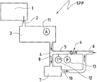
- FIG. 2 represents in a diagrammatic way a system of vacuum pumps suitable for implementation of a pumping method according to a second embodiment of the present invention
- FIG. 3 represents in a diagrammatic way the system of vacuum pumps according to the first embodiment, showing the feature wherein an auxiliary lubricated rotary vane vacuum pump ejects gas into an oil separator of a main lubricated rotary vane vacuum pump; and
- FIG. 4 represents in a diagrammatic way the system of vacuum pumps according to the second embodiment, showing the feature wherein an auxiliary lubricated rotary vane vacuum pump is incorporated in an oil separator of a main lubricated rotary vane vacuum pump.
- FIG. 1 represents a pumping system SP suitable for implementing a pumping method according to a first embodiment of the present invention.
- This system of vacuum pumps SP comprises a chamber 1 , which is connected to the suction port 2 of a main lubricated rotary vane vacuum pump 3 .
- the gas outlet port of the main lubricated rotary vane vacuum pump 3 is connected to a conduit 5 .
- a non-return discharge valve 6 is placed in the conduit 5 , which after this non-return valve continues into a gas exit conduit 8 .
- the non-return valve 6 when it is closed, allows the formation of a space 4 , contained between the gas outlet port of the main vacuum pump 3 and itself.
- the system of vacuum pumps SP also comprises an auxiliary lubricated rotary vane vacuum pump 7 , connected in parallel to the non-return valve 6 .
- the suction port 9 of the auxiliary lubricated rotary vane vacuum pump 7 is connected to the space 4 of the conduit 5 , and its discharge port 10 is connected to the conduit 8 .
- the auxiliary lubricated rotary vane vacuum pump 7 is also started up.
- the main lubricated rotary vane vacuum pump 3 suctions the gases in the chamber 1 through the port 2 connected at its inlet and compresses them to discharge them afterwards at its outlet in the conduit 5 and then through the non-return valve 6 .
- the closure pressure for the non-return valve 6 is reached, it closes.
- the pumping of the auxiliary lubricated rotary vane vacuum pump 7 makes the pressure in the space 4 decrease progressively to its limit pressure.
- the power consumed by the main lubricated rotary vane vacuum pump 3 decreases progressively. This takes place in a short time period, for example for a certain cycle in 5 to 10 seconds.
- FIG. 2 represents a system of vacuum pumps SP suitable for implementation of a pumping method according to a second embodiment of the present invention.
- the system represented in FIG. 2 represents the “controlled” pumping system SPP, which further comprises suitable sensors 11 , 12 , 13 which control either the motor current (sensor 11 ) of the main lubricated rotary vane vacuum pump 3 , or the pressure (sensor 13 ) of the gases in the space of the exit conduit of the main lubricated rotary vane vacuum pump, limited by the non-return valve 6 , or the temperature (sensor 12 ) of the gases in the space of the exit conduit of the main lubricated rotary vane vacuum pump, limited by the non-return valve 6 , or a combination of these parameters.
- suitable sensors 11 , 12 , 13 which control either the motor current (sensor 11 ) of the main lubricated rotary vane vacuum pump 3 , or the pressure (sensor 13 ) of the gases in the space of the exit conduit of the main lubricated rotary vane vacuum pump, limited by the non-return valve 6 , or the temperature (sensor 12 ) of the gases in the space of the exit conduit of the main
- the auxiliary lubricated rotary vane vacuum pump 7 ejects the gas into an oil separator 14 of the main lubricated rotary vane vacuum pump 3 .
- the auxiliary lubricated rotary vane vacuum pump 7 is incorporated in an oil separator 14 ′ of the main lubricated rotary vane vacuum pump 3 .
- the parameters such as the current of its motor, the temperature and the pressure of the gases in the space of the exit conduit 4 , begin to change and reach threshold values detected by the sensors.
- the threshold value can be a percentage of the maximum value measured during an evacuation cycle without activation of the auxiliary vacuum pump (for example 75%).
- the threshold value can be a percentage (for example 80%) of the maximum value measured during an evacuation cycle without activation of the auxiliary vacuum pump.
- the threshold value (for example 100 mbar) is defined as a function in relation to the flow rates of the two pumps, the main one and the auxiliary one.
Abstract
Description
Claims (9)
Applications Claiming Priority (1)
| Application Number | Priority Date | Filing Date | Title |
|---|---|---|---|
| PCT/EP2014/063725 WO2015197138A1 (en) | 2014-06-27 | 2014-06-27 | Method of pumping in a system of vacuum pumps and system of vacuum pumps |
Related Parent Applications (1)
| Application Number | Title | Priority Date | Filing Date |
|---|---|---|---|
| PCT/EP2014/063725 A-371-Of-International WO2015197138A1 (en) | 2014-06-27 | 2014-06-27 | Method of pumping in a system of vacuum pumps and system of vacuum pumps |
Related Child Applications (1)
| Application Number | Title | Priority Date | Filing Date |
|---|---|---|---|
| US16/868,460 Division US11725662B2 (en) | 2014-06-27 | 2020-05-06 | Method of pumping in a system of vacuum pumps and system of vacuum pumps |
Publications (2)
| Publication Number | Publication Date |
|---|---|
| US20170122321A1 US20170122321A1 (en) | 2017-05-04 |
| US10760573B2 true US10760573B2 (en) | 2020-09-01 |
Family
ID=51177037
Family Applications (2)
| Application Number | Title | Priority Date | Filing Date |
|---|---|---|---|
| US15/321,839 Active 2034-12-27 US10760573B2 (en) | 2014-06-27 | 2014-06-27 | Method of pumping in a system of vacuum pumps and system of vacuum pumps |
| US16/868,460 Active 2034-07-17 US11725662B2 (en) | 2014-06-27 | 2020-05-06 | Method of pumping in a system of vacuum pumps and system of vacuum pumps |
Family Applications After (1)
| Application Number | Title | Priority Date | Filing Date |
|---|---|---|---|
| US16/868,460 Active 2034-07-17 US11725662B2 (en) | 2014-06-27 | 2020-05-06 | Method of pumping in a system of vacuum pumps and system of vacuum pumps |
Country Status (15)
| Country | Link |
|---|---|
| US (2) | US10760573B2 (en) |
| EP (1) | EP3161318B1 (en) |
| JP (1) | JP6608394B2 (en) |
| KR (1) | KR102223057B1 (en) |
| CN (1) | CN106662108A (en) |
| AU (3) | AU2014398770A1 (en) |
| BR (1) | BR112016030498B1 (en) |
| CA (1) | CA2953455C (en) |
| DK (1) | DK3161318T3 (en) |
| ES (1) | ES2774438T3 (en) |
| PL (1) | PL3161318T3 (en) |
| PT (1) | PT3161318T (en) |
| RU (1) | RU2666720C2 (en) |
| TW (2) | TWI734588B (en) |
| WO (1) | WO2015197138A1 (en) |
Cited By (1)
| Publication number | Priority date | Publication date | Assignee | Title |
|---|---|---|---|---|
| US11725662B2 (en) * | 2014-06-27 | 2023-08-15 | Ateliers Busch Sa | Method of pumping in a system of vacuum pumps and system of vacuum pumps |
Families Citing this family (4)
| Publication number | Priority date | Publication date | Assignee | Title |
|---|---|---|---|---|
| JP6785695B2 (en) * | 2016-06-08 | 2020-11-18 | 株式会社荏原製作所 | Dry vacuum pump with abatement function |
| US10982663B2 (en) * | 2017-05-30 | 2021-04-20 | Ulvac, Inc. | Vacuum pump |
| CN107559200A (en) * | 2017-11-01 | 2018-01-09 | 广东肯富来泵业股份有限公司 | Balanced type Roots vacuum pumping system and its control method |
| CN107701482A (en) * | 2017-11-15 | 2018-02-16 | 益发施迈茨工业炉(上海)有限公司 | The auxiliary starting system and method for vacuum drying oven motor |
Citations (30)
| Publication number | Priority date | Publication date | Assignee | Title |
|---|---|---|---|---|
| US3536418A (en) * | 1969-02-13 | 1970-10-27 | Onezime P Breaux | Cryogenic turbo-molecular vacuum pump |
| US3707339A (en) * | 1969-06-12 | 1972-12-26 | British Oxygen Co Ltd | Vacuum pumps |
| US4426450A (en) | 1981-08-24 | 1984-01-17 | Fermentec Corporation | Fermentation process and apparatus |
| DE3842886A1 (en) | 1987-12-21 | 1989-07-06 | Rietschle Masch App | Vacuum pump stand |
| DE3819692A1 (en) * | 1988-06-09 | 1989-12-14 | Provac Gmbh & Co | Dry-running slide vane rotary vacuum pump |
| US5004407A (en) * | 1989-09-26 | 1991-04-02 | Sundstrand Corporation | Method of scavenging air and oil and gear pump therefor |
| DE8816875U1 (en) | 1987-12-21 | 1991-04-11 | Werner Rietschle Maschinen- Und Apparatebau Gmbh, 7860 Schopfheim, De | |
| US5697771A (en) * | 1993-08-17 | 1997-12-16 | Leybold Aktiengesellschaft | Vacuum pump with oil separator |
| US6123516A (en) * | 1997-03-06 | 2000-09-26 | Leybold Vakuum Gmbh | Vacuum pump |
| US20020131870A1 (en) | 2001-03-19 | 2002-09-19 | Alcatel | System for pumping low thermal conductivity gases |
| US20030068233A1 (en) * | 2001-10-09 | 2003-04-10 | Applied Materials, Inc. | Device and method for reducing vacuum pump energy consumption |
| US20040173312A1 (en) * | 2001-09-06 | 2004-09-09 | Kouji Shibayama | Vacuum exhaust apparatus and drive method of vacuum apparatus |
| US20040261792A1 (en) | 2001-07-02 | 2004-12-30 | Boehringer Ingelheim Pharma Gmbh & Co. Kg | Control unit for flow regulation |
| US20050268644A1 (en) | 2004-02-18 | 2005-12-08 | Denso Corporation | Vapor compression cycle having ejector |
| US20060086649A1 (en) | 2004-10-26 | 2006-04-27 | Wieczorek Mark T | Automatic water drain for suction fuel water separators |
| US20060182638A1 (en) | 2003-03-03 | 2006-08-17 | Tadahiro Ohmi | Vacuum device and vacuum pump |
| JP2007100562A (en) | 2005-10-03 | 2007-04-19 | Shinko Seiki Co Ltd | Vacuum device |
| US20070286749A1 (en) * | 2006-05-16 | 2007-12-13 | Pfeiffer Vacuum Gmbh | Drive for vacuum pump |
| US20080145209A1 (en) * | 2006-12-13 | 2008-06-19 | Pfeiffer Vacuum Gmbh | Lubricant-tight vane rotary vacuum pump |
| US20080166247A1 (en) | 2005-02-26 | 2008-07-10 | Michael Holzemer | Single-Shaft Vacuum Positive Displacement Pump |
| US20090112370A1 (en) | 2005-07-21 | 2009-04-30 | Asm Japan K.K. | Vacuum system and method for operating the same |
| US20090246040A1 (en) * | 2008-03-24 | 2009-10-01 | Anest Iwata Corporation | Multistage Vacuum Pump Unit and an Operation Method Thereof |
| FR2952683A1 (en) | 2009-11-18 | 2011-05-20 | Alcatel Lucent | METHOD AND APPARATUS FOR PUMPING WITH REDUCED ENERGY CONSUMPTION |
| US20110164992A1 (en) | 2008-09-10 | 2011-07-07 | Ulvac, Inc. | Vacuum evacuation device |
| US20110263406A1 (en) | 2008-11-14 | 2011-10-27 | Mann+Hummel Gmbh | Centrifugal separator with venturi arrangement |
| US20120080134A1 (en) | 2005-01-20 | 2012-04-05 | Jaime Leonard Harris | Eductor assembly with dual-material eductor body |
| WO2014012896A2 (en) | 2012-07-19 | 2014-01-23 | Adixen Vacuum Products | Method and device for pumping of a process chamber |
| DE102012220442A1 (en) | 2012-11-09 | 2014-05-15 | Oerlikon Leybold Vacuum Gmbh | Vacuum pump system for evacuating a chamber and method for controlling a vacuum pump system |
| US20150308461A1 (en) | 2012-12-21 | 2015-10-29 | Xerex Ab | Vacuum Ejector With Multi-Nozzle Drive Stage And Booster |
| US20150345496A1 (en) * | 2012-12-27 | 2015-12-03 | Vhit S.P.A. | Lubrication system for a rotary vacuum pump |
Family Cites Families (20)
| Publication number | Priority date | Publication date | Assignee | Title |
|---|---|---|---|---|
| SU1170190A1 (en) * | 1984-01-17 | 1985-07-30 | Предприятие П/Я А-1614 | Lubricating system of mechanical vacuum pump |
| JPH0776553B2 (en) * | 1986-02-14 | 1995-08-16 | 株式会社島津製作所 | Multiple-type oil rotary vacuum pump |
| JPS62233492A (en) | 1986-03-31 | 1987-10-13 | Shimadzu Corp | Oil rotating vacuum pump |
| JPS63104693A (en) * | 1986-10-22 | 1988-05-10 | Nissho:Kk | Treatment of industrial waste |
| JPH0442557Y2 (en) * | 1986-12-25 | 1992-10-07 | ||
| SU1700283A1 (en) * | 1989-05-05 | 1991-12-23 | Предприятие П/Я А-3634 | Vacuum pump |
| JPH0436091A (en) * | 1990-05-29 | 1992-02-06 | Shimadzu Corp | Oil-sealed rotary vacuum pump |
| KR100190310B1 (en) * | 1992-09-03 | 1999-06-01 | 모리시따 요오이찌 | Two stage primary dry pump |
| JP3386202B2 (en) * | 1993-09-08 | 2003-03-17 | 株式会社アルバック | Two-stage oil rotary vacuum pump |
| JP3992176B2 (en) * | 2001-10-26 | 2007-10-17 | 株式会社アルバック | Vacuum exhaust method and vacuum exhaust device |
| DE10150015A1 (en) * | 2001-10-11 | 2003-04-17 | Leybold Vakuum Gmbh | Multiple chamber plant used for degassing, coating or etching substrates comprises an evacuating system connected to chambers |
| JP4365059B2 (en) | 2001-10-31 | 2009-11-18 | 株式会社アルバック | Operation method of vacuum exhaust system |
| JP4077196B2 (en) * | 2001-12-25 | 2008-04-16 | 滋 山口 | Oil rotary vacuum pump |
| FR2869369B1 (en) * | 2004-04-21 | 2006-07-21 | Alcatel Sa | VACUUM PUMP MULTI-STAGE, AND PUMPING INSTALLATION COMPRISING SUCH A PUMP |
| US7632084B2 (en) * | 2004-08-02 | 2009-12-15 | Panasonic Corporation | Oilless rotary vane pump having open ends of vane grooves being inclined rearward in the rotation direction |
| WO2007003215A1 (en) * | 2005-07-05 | 2007-01-11 | Vhit S.P.A. | Vacuum vane pump with discharge valve |
| JP5303249B2 (en) * | 2008-11-26 | 2013-10-02 | 株式会社荏原製作所 | Dry vacuum pump unit |
| DE102009024336A1 (en) * | 2009-06-09 | 2010-12-23 | Oerlikon Leybold Vacuum Gmbh | vacuum pump |
| JP5677202B2 (en) * | 2011-06-02 | 2015-02-25 | 株式会社荏原製作所 | Vacuum pump |
| RU2666720C2 (en) * | 2014-06-27 | 2018-09-11 | Ателье Буш Са | Method of evacuation in the vacuum pump system and vacuum pump system |
-
2014
- 2014-06-27 RU RU2017102492A patent/RU2666720C2/en active
- 2014-06-27 CN CN201480080173.7A patent/CN106662108A/en active Pending
- 2014-06-27 JP JP2016574254A patent/JP6608394B2/en active Active
- 2014-06-27 AU AU2014398770A patent/AU2014398770A1/en not_active Abandoned
- 2014-06-27 PL PL14738765T patent/PL3161318T3/en unknown
- 2014-06-27 KR KR1020177002586A patent/KR102223057B1/en active IP Right Grant
- 2014-06-27 WO PCT/EP2014/063725 patent/WO2015197138A1/en active Application Filing
- 2014-06-27 CA CA2953455A patent/CA2953455C/en active Active
- 2014-06-27 EP EP14738765.8A patent/EP3161318B1/en not_active Revoked
- 2014-06-27 ES ES14738765T patent/ES2774438T3/en active Active
- 2014-06-27 US US15/321,839 patent/US10760573B2/en active Active
- 2014-06-27 DK DK14738765.8T patent/DK3161318T3/en active
- 2014-06-27 BR BR112016030498-5A patent/BR112016030498B1/en active IP Right Grant
- 2014-06-27 PT PT147387658T patent/PT3161318T/en unknown
-
2015
- 2015-06-25 TW TW109127956A patent/TWI734588B/en active
- 2015-06-25 TW TW104120571A patent/TWI710702B/en active
-
2017
- 2017-03-22 AU AU2017100332A patent/AU2017100332A4/en not_active Expired
-
2019
- 2019-06-28 AU AU2019204608A patent/AU2019204608B2/en active Active
-
2020
- 2020-05-06 US US16/868,460 patent/US11725662B2/en active Active
Patent Citations (38)
| Publication number | Priority date | Publication date | Assignee | Title |
|---|---|---|---|---|
| US3536418A (en) * | 1969-02-13 | 1970-10-27 | Onezime P Breaux | Cryogenic turbo-molecular vacuum pump |
| US3707339A (en) * | 1969-06-12 | 1972-12-26 | British Oxygen Co Ltd | Vacuum pumps |
| US4426450A (en) | 1981-08-24 | 1984-01-17 | Fermentec Corporation | Fermentation process and apparatus |
| DE3842886A1 (en) | 1987-12-21 | 1989-07-06 | Rietschle Masch App | Vacuum pump stand |
| DE8816875U1 (en) | 1987-12-21 | 1991-04-11 | Werner Rietschle Maschinen- Und Apparatebau Gmbh, 7860 Schopfheim, De | |
| DE3819692A1 (en) * | 1988-06-09 | 1989-12-14 | Provac Gmbh & Co | Dry-running slide vane rotary vacuum pump |
| US5004407A (en) * | 1989-09-26 | 1991-04-02 | Sundstrand Corporation | Method of scavenging air and oil and gear pump therefor |
| US5697771A (en) * | 1993-08-17 | 1997-12-16 | Leybold Aktiengesellschaft | Vacuum pump with oil separator |
| US6123516A (en) * | 1997-03-06 | 2000-09-26 | Leybold Vakuum Gmbh | Vacuum pump |
| US20020131870A1 (en) | 2001-03-19 | 2002-09-19 | Alcatel | System for pumping low thermal conductivity gases |
| EP1243795A1 (en) | 2001-03-19 | 2002-09-25 | Alcatel | A two-stage vacuum pump |
| US6644931B2 (en) | 2001-03-19 | 2003-11-11 | Alcatel | System for pumping low thermal conductivity gases |
| US20040261792A1 (en) | 2001-07-02 | 2004-12-30 | Boehringer Ingelheim Pharma Gmbh & Co. Kg | Control unit for flow regulation |
| US20040173312A1 (en) * | 2001-09-06 | 2004-09-09 | Kouji Shibayama | Vacuum exhaust apparatus and drive method of vacuum apparatus |
| US20080145238A1 (en) | 2001-09-06 | 2008-06-19 | Kouji Shibayama | Vacuum exhaust apparatus and drive method of vacuum exhaust apparatus |
| US20030068233A1 (en) * | 2001-10-09 | 2003-04-10 | Applied Materials, Inc. | Device and method for reducing vacuum pump energy consumption |
| US6589023B2 (en) | 2001-10-09 | 2003-07-08 | Applied Materials, Inc. | Device and method for reducing vacuum pump energy consumption |
| US20060182638A1 (en) | 2003-03-03 | 2006-08-17 | Tadahiro Ohmi | Vacuum device and vacuum pump |
| US20050268644A1 (en) | 2004-02-18 | 2005-12-08 | Denso Corporation | Vapor compression cycle having ejector |
| US20060086649A1 (en) | 2004-10-26 | 2006-04-27 | Wieczorek Mark T | Automatic water drain for suction fuel water separators |
| US20120080134A1 (en) | 2005-01-20 | 2012-04-05 | Jaime Leonard Harris | Eductor assembly with dual-material eductor body |
| US20080166247A1 (en) | 2005-02-26 | 2008-07-10 | Michael Holzemer | Single-Shaft Vacuum Positive Displacement Pump |
| US20090112370A1 (en) | 2005-07-21 | 2009-04-30 | Asm Japan K.K. | Vacuum system and method for operating the same |
| JP2007100562A (en) | 2005-10-03 | 2007-04-19 | Shinko Seiki Co Ltd | Vacuum device |
| US20070286749A1 (en) * | 2006-05-16 | 2007-12-13 | Pfeiffer Vacuum Gmbh | Drive for vacuum pump |
| US20080145209A1 (en) * | 2006-12-13 | 2008-06-19 | Pfeiffer Vacuum Gmbh | Lubricant-tight vane rotary vacuum pump |
| US20090246040A1 (en) * | 2008-03-24 | 2009-10-01 | Anest Iwata Corporation | Multistage Vacuum Pump Unit and an Operation Method Thereof |
| US20110164992A1 (en) | 2008-09-10 | 2011-07-07 | Ulvac, Inc. | Vacuum evacuation device |
| US20110263406A1 (en) | 2008-11-14 | 2011-10-27 | Mann+Hummel Gmbh | Centrifugal separator with venturi arrangement |
| FR2952683A1 (en) | 2009-11-18 | 2011-05-20 | Alcatel Lucent | METHOD AND APPARATUS FOR PUMPING WITH REDUCED ENERGY CONSUMPTION |
| US20120219443A1 (en) | 2009-11-18 | 2012-08-30 | Adixen Vacuum Products | Method And Device For Pumping With Reduced Power Use |
| US9175688B2 (en) | 2009-11-18 | 2015-11-03 | Adixen Vacuum Products | Vacuum pumping system having an ejector and check valve |
| WO2014012896A2 (en) | 2012-07-19 | 2014-01-23 | Adixen Vacuum Products | Method and device for pumping of a process chamber |
| US20150170938A1 (en) | 2012-07-19 | 2015-06-18 | Adixen Vacuum Products | Method and device for pumping of a process chamber |
| US9558969B2 (en) | 2012-07-19 | 2017-01-31 | Adixen Vacuum Products | Method and device for pumping of a process chamber |
| DE102012220442A1 (en) | 2012-11-09 | 2014-05-15 | Oerlikon Leybold Vacuum Gmbh | Vacuum pump system for evacuating a chamber and method for controlling a vacuum pump system |
| US20150308461A1 (en) | 2012-12-21 | 2015-10-29 | Xerex Ab | Vacuum Ejector With Multi-Nozzle Drive Stage And Booster |
| US20150345496A1 (en) * | 2012-12-27 | 2015-12-03 | Vhit S.P.A. | Lubrication system for a rotary vacuum pump |
Non-Patent Citations (10)
| Title |
|---|
| Final Office Action issued in U.S. Appl. No. 15/306,175, dated Jan. 24, 2019. |
| Final Office Action issued in U.S. Appl. No. 15/512,883, dated Jul. 11, 2019. |
| Final Office Action issued in U.S. Appl. No. 15/513,574, dated Dec. 12, 2019. |
| International Search Report and Written Opinion for PCT/EP2014/070691, dated Mar. 11, 2015, 12 pages. |
| International Search Report and Written Opinion for PCT/EP2014/071197, dated Mar. 9, 2015, 12 pages. |
| International Search Report for PCT/EP2014/058948, dated May 28, 2014, 4 pages. |
| International Search Report for PCT/EP2014/063725 dated Mar. 9, 2015, 11 pgs. |
| Non-Final Office Action issued in U.S. Appl. No. 15/306,175, dated Jun. 29, 2018. |
| Non-Final Office Action issued in U.S. Appl. No. 15/512,883, dated Feb. 25, 2019. |
| Non-Final Office Action issued in U.S. Appl. No. 15/513,574, dated Aug. 15, 2019. |
Cited By (1)
| Publication number | Priority date | Publication date | Assignee | Title |
|---|---|---|---|---|
| US11725662B2 (en) * | 2014-06-27 | 2023-08-15 | Ateliers Busch Sa | Method of pumping in a system of vacuum pumps and system of vacuum pumps |
Also Published As
| Publication number | Publication date |
|---|---|
| RU2017102492A3 (en) | 2018-07-27 |
| US11725662B2 (en) | 2023-08-15 |
| DK3161318T3 (en) | 2020-03-09 |
| AU2014398770A1 (en) | 2017-01-19 |
| CN106662108A (en) | 2017-05-10 |
| WO2015197138A1 (en) | 2015-12-30 |
| CA2953455C (en) | 2022-03-29 |
| CA2953455A1 (en) | 2015-12-30 |
| AU2019204608A1 (en) | 2019-07-18 |
| TW201608135A (en) | 2016-03-01 |
| RU2017102492A (en) | 2018-07-27 |
| US20200318640A1 (en) | 2020-10-08 |
| JP6608394B2 (en) | 2019-11-20 |
| TWI734588B (en) | 2021-07-21 |
| KR20170028381A (en) | 2017-03-13 |
| PT3161318T (en) | 2020-03-06 |
| TWI710702B (en) | 2020-11-21 |
| EP3161318B1 (en) | 2020-02-05 |
| BR112016030498A2 (en) | 2017-08-22 |
| BR112016030498B1 (en) | 2022-06-28 |
| JP2017523339A (en) | 2017-08-17 |
| AU2019204608B2 (en) | 2021-07-22 |
| US20170122321A1 (en) | 2017-05-04 |
| PL3161318T3 (en) | 2020-08-10 |
| RU2666720C2 (en) | 2018-09-11 |
| AU2017100332A4 (en) | 2017-04-27 |
| TW202043623A (en) | 2020-12-01 |
| ES2774438T3 (en) | 2020-07-21 |
| EP3161318A1 (en) | 2017-05-03 |
| KR102223057B1 (en) | 2021-03-05 |
Similar Documents
| Publication | Publication Date | Title |
|---|---|---|
| US11725662B2 (en) | Method of pumping in a system of vacuum pumps and system of vacuum pumps | |
| US10808730B2 (en) | Pumping system for generating a vacuum and method for pumping by means of this pumping system | |
| AU2014406724B2 (en) | Vacuum-generating pumping system and pumping method using this pumping system | |
| AU2014392229B2 (en) | Method of pumping in a pumping system and vacuum pump system | |
| US10260502B2 (en) | Pumping method in a system of vacuum pumps and system of vacuum pumps |
Legal Events
| Date | Code | Title | Description |
|---|---|---|---|
| AS | Assignment |
Owner name: ATELIERS BUSCH SA, SWITZERLAND Free format text: ASSIGNMENT OF ASSIGNORS INTEREST;ASSIGNORS:MUELLER, DIDIER;LARCHER, JEAN-ERIC;ILTCHEV, THEODORE;REEL/FRAME:041787/0538 Effective date: 20170221 |
|
| STPP | Information on status: patent application and granting procedure in general |
Free format text: RESPONSE TO NON-FINAL OFFICE ACTION ENTERED AND FORWARDED TO EXAMINER |
|
| STPP | Information on status: patent application and granting procedure in general |
Free format text: FINAL REJECTION MAILED |
|
| STPP | Information on status: patent application and granting procedure in general |
Free format text: FINAL REJECTION MAILED |
|
| STPP | Information on status: patent application and granting procedure in general |
Free format text: DOCKETED NEW CASE - READY FOR EXAMINATION |
|
| STPP | Information on status: patent application and granting procedure in general |
Free format text: NON FINAL ACTION MAILED |
|
| STPP | Information on status: patent application and granting procedure in general |
Free format text: PUBLICATIONS -- ISSUE FEE PAYMENT RECEIVED |
|
| STCF | Information on status: patent grant |
Free format text: PATENTED CASE |
|
| MAFP | Maintenance fee payment |
Free format text: PAYMENT OF MAINTENANCE FEE, 4TH YEAR, LARGE ENTITY (ORIGINAL EVENT CODE: M1551); ENTITY STATUS OF PATENT OWNER: LARGE ENTITY Year of fee payment: 4 |