US10713826B2 - Computer-implemented method for drawing a polyline in a three-dimensional scene - Google Patents
Computer-implemented method for drawing a polyline in a three-dimensional scene Download PDFInfo
- Publication number
- US10713826B2 US10713826B2 US15/371,642 US201615371642A US10713826B2 US 10713826 B2 US10713826 B2 US 10713826B2 US 201615371642 A US201615371642 A US 201615371642A US 10713826 B2 US10713826 B2 US 10713826B2
- Authority
- US
- United States
- Prior art keywords
- segment
- computer
- polyline
- graphical tool
- planes
- Prior art date
- Legal status (The legal status is an assumption and is not a legal conclusion. Google has not performed a legal analysis and makes no representation as to the accuracy of the status listed.)
- Active
Links
Images


Classifications
-
- G—PHYSICS
- G06—COMPUTING OR CALCULATING; COUNTING
- G06F—ELECTRIC DIGITAL DATA PROCESSING
- G06F30/00—Computer-aided design [CAD]
- G06F30/20—Design optimisation, verification or simulation
-
- G—PHYSICS
- G06—COMPUTING OR CALCULATING; COUNTING
- G06T—IMAGE DATA PROCESSING OR GENERATION, IN GENERAL
- G06T19/00—Manipulating 3D models or images for computer graphics
- G06T19/20—Editing of 3D images, e.g. changing shapes or colours, aligning objects or positioning parts
-
- G—PHYSICS
- G06—COMPUTING OR CALCULATING; COUNTING
- G06T—IMAGE DATA PROCESSING OR GENERATION, IN GENERAL
- G06T11/00—2D [Two Dimensional] image generation
- G06T11/20—Drawing from basic elements, e.g. lines or circles
- G06T11/203—Drawing of straight lines or curves
-
- G—PHYSICS
- G06—COMPUTING OR CALCULATING; COUNTING
- G06F—ELECTRIC DIGITAL DATA PROCESSING
- G06F30/00—Computer-aided design [CAD]
-
- G—PHYSICS
- G06—COMPUTING OR CALCULATING; COUNTING
- G06F—ELECTRIC DIGITAL DATA PROCESSING
- G06F30/00—Computer-aided design [CAD]
- G06F30/10—Geometric CAD
-
- G—PHYSICS
- G06—COMPUTING OR CALCULATING; COUNTING
- G06T—IMAGE DATA PROCESSING OR GENERATION, IN GENERAL
- G06T19/00—Manipulating 3D models or images for computer graphics
-
- G06T3/0081—
-
- G—PHYSICS
- G06—COMPUTING OR CALCULATING; COUNTING
- G06T—IMAGE DATA PROCESSING OR GENERATION, IN GENERAL
- G06T3/00—Geometric image transformations in the plane of the image
- G06T3/14—Transformations for image registration, e.g. adjusting or mapping for alignment of images
- G06T3/153—Transformations for image registration, e.g. adjusting or mapping for alignment of images using elastic snapping
-
- G—PHYSICS
- G06—COMPUTING OR CALCULATING; COUNTING
- G06T—IMAGE DATA PROCESSING OR GENERATION, IN GENERAL
- G06T3/00—Geometric image transformations in the plane of the image
- G06T3/40—Scaling of whole images or parts thereof, e.g. expanding or contracting
-
- G—PHYSICS
- G06—COMPUTING OR CALCULATING; COUNTING
- G06T—IMAGE DATA PROCESSING OR GENERATION, IN GENERAL
- G06T2200/00—Indexing scheme for image data processing or generation, in general
- G06T2200/24—Indexing scheme for image data processing or generation, in general involving graphical user interfaces [GUIs]
-
- G—PHYSICS
- G06—COMPUTING OR CALCULATING; COUNTING
- G06T—IMAGE DATA PROCESSING OR GENERATION, IN GENERAL
- G06T2207/00—Indexing scheme for image analysis or image enhancement
- G06T2207/20—Special algorithmic details
- G06T2207/20092—Interactive image processing based on input by user
-
- G—PHYSICS
- G06—COMPUTING OR CALCULATING; COUNTING
- G06T—IMAGE DATA PROCESSING OR GENERATION, IN GENERAL
- G06T2219/00—Indexing scheme for manipulating 3D models or images for computer graphics
- G06T2219/016—Exploded view
-
- G—PHYSICS
- G06—COMPUTING OR CALCULATING; COUNTING
- G06T—IMAGE DATA PROCESSING OR GENERATION, IN GENERAL
- G06T2219/00—Indexing scheme for manipulating 3D models or images for computer graphics
- G06T2219/20—Indexing scheme for editing of 3D models
- G06T2219/2004—Aligning objects, relative positioning of parts
Definitions
- the invention relates to a computer-implemented method for drawing a polyline, i.e. a broken line, in a three-dimensional (3D) scene.
- the polyline may, in particular, be an assembly path, i.e. a polyline used to illustrate how the elements of a system, shown in an exploded view, are assembled.
- the invention applies to the field of computer graphics, and more particularly to the field of Computer Aided Design (CAD) and illustration authoring.
- CAD Computer Aided Design
- the invention is particularly suitable for producing technical illustrations, marketing presentations, assembly illustrations, training materials etc.
- FIG. 1 An example of such an exploded view is provided in FIG. 1 .
- dashed polylines AL called “assembly lines”, are used to indicate the original location of the parts and the way they have been removed from there (assembly paths).
- the segments of the polyline are mutually perpendicular and usually oriented parallel or perpendicular to a “world axis” of the view.
- a first possibility for designing assembly lines consists in drawing the polylines freely in the plane defined by the current point of view. Otherwise stated, the polyline is drawn in two dimensions (2D), and automatically integrated into the three-dimensional representation of the scene.
- the angle between consecutive segments of the polyline may not take accurate values (e.g. 45° or 90°); most importantly, as the polyline is not properly situated in three-dimensions, they are lost if the user changes the point of view.
- FIG. 2 the left part of the figure shows a polyline drawn in two-dimensions, which gives the illusion of being constituted of mutually perpendicular segments in 2D space; the illusion is completely lost if the scene is rotated in three dimensions.
- FIG. 3 Another approach, illustrated on FIG. 3 , uses planar grids to properly draw the segments of the polyline.
- a drawback of this technique is that it is quite cumbersome to create and position a grid before drawing each segment.
- drawing a complex three-dimensional polyline requires the simultaneous display of several grids, which may be confusing for the user and demanding (essentially in terms of memory space) for the Computer Aided Design/illustration authoring system.
- Yet another approach is to use software for automatically creating a path (i.e. a polyline) between the original position of a part to a new one.
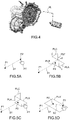
- This approach is not flexible enough, as the user has no control on the position of the “breakings” of the line. The result is often unsatisfactory for a human end user, as depicted on FIG. 4 .
- the invention aims at overcoming these drawbacks of the prior art. More specifically the invention aims at providing a simple and effective method for drawing polylines in a three-dimensional scene, with a sufficient degree of flexibility and yet allowing an accurate determination of the angles between segments of the polyline.
- this aim is achieved by the use of a particular graphical tool, which may be called a “plane selector”.
- This tool is displayed for the first time after the drawing of a first segment; it allows the user to select a plane parallel or perpendicular to this segment, then creates a grid “on the fly” on the selected plane to ease the drawing of the successive segment, and so on.
- This way the user can draw the polyline step by step, choosing the positioning on the breakings and (with some constraints) the angles formed by the different segments, while being relieved from the burden of manually positioning the drawing grids.
- An object of the present invention is then a computer-implemented method for drawing a polyline (AL) in a three-dimensional scene comprising the steps of:
- Another object of the invention is a computer program product, stored on a non-volatile computer-readable data-storage medium, comprising computer-executable instructions to cause a computer system to carry out such a method.
- Another object of the invention is a non-volatile computer-readable data-storage medium containing computer-executable instructions to cause a computer system to carry out such a method.
- Another object of the invention is a Computer Aided Design system comprising a processor coupled to a memory and a graphical user interface, the memory storing computer-executable instructions to cause the Computer Aided Design system to carry out such a method.
- Yet another object of the invention is a three-dimensional illustration authoring system comprising a processor coupled to a memory and a graphical user interface, the memory storing computer-executable instructions to cause the three-dimensional illustration authoring system to carry out such a method.
- FIG. 1 described above, the exploded view of a mechanical assembly, showing a plurality of assembly lines;
- FIGS. 2 to 4 also described above, assembly lines drawn using methods known from the prior art
- FIGS. 5A to 5D the step of a method according to an embodiment of the invention.
- FIGS. 6 and 7A-7C alternative embodiments of the step illustrated by FIG. 5D ;
- FIGS. 8A and 8B the drawing of a freely-oriented segment
- FIGS. 9A-9D the application of the invention to the drawing of an assembly line in the exploded view of a mechanical assembly.
- FIGS. 10 and 11 block diagrams of respective computer systems suitable for carrying out a method according to different embodiments of the invention.
- a “three-dimensional” (or “3D”) object will be an object, or rather its digital representation in a computer system, allowing a three-dimensional (3D) graphical representation.
- a 3D representation allows the viewing of the part from all angles.
- a 3D object when 3D represented, may be handled and turned around any of its axes, or around any axis in the screen on which the representation is displayed.
- a three-dimensional scene is constituted by a plurality of 3D objects disposed in a three-dimensional space.
- a “two-dimensional” (or “2D”) object will be an object only allowing a two-dimensional (2D) representation e.g. on a plane.
- a 2D object may only be translated in the plane of the screen on which the representation is displayed, or rotated around an axis perpendicular to said screen.
- the first step of the inventive method consists in drawing a first segment S 1 of the polyline.
- the direction of the first segment is freely chosen by the user; it may, for instance correspond to that of an axis of a piece of the assembly.
- the user selects a first anchor point P 1 (starting point) and a second anchor point P 2 (endpoint) of the three-dimensional scene using a pointer tool PT moved e.g. using a pointing device such as a mouse, a roller ball or a track pad, or a touch screen.
- a pointing device such as a mouse, a roller ball or a track pad, or a touch screen.
- There are different ways for selecting a point in 3D using a pointing device For example:
- the Computer Aided Design or illustration authoring system traces the segment S 1 by linking the starting point P 1 to the endpoint P 2 .
- the Computer Aided Design or illustration authoring system may continuously trace a segment linking the starting point P 1 to the pointer tool PT, until the endpoint P 2 is selected thus “fixing” the direction of the segment.
- the Computer Aided Design or illustration authoring system displays a graphical tool PST—called a “plane selector”—near to or overlapping the endpoint P 2 of the first segment.
- the plane selector PST comprises a symbolic representation of three mutually orthogonal planes, one of which (reference PLA) is perpendicular to the segment S 1 while the two others (PLB, PLC) are parallel to it. Otherwise stated, the planes PLA, PLB, PLC correspond to the “xy”, “xz” and “yz” planes of an orthonormal coordinate system xyz, wherein the “y” axis has the direction of the segment S 1 .
- the endpoint P 2 of the first segment belongs to all of the three planes, and therefore it constitutes the origin of the orthonormal coordinate system xyz. This is not apparent on FIG. 5B , because the plane selector PST only provides a symbolic representation of the planes.
- the plane selector has the appearance of a “half cube”, but this is not essential.
- the user selects one of the planes (e.g. PLA) of the plane selector, for instance by placing the pointer tool PT on it and by “clicking” on a button of the pointing device; see FIG. 5C .
- the plane selector PLC is no more required and may disappear or fade away; instead, an enlarged representation PLA′ of the selected plane is displayed; this representation may consists in a rectangle lying in the plane, which is conceptually infinite.
- Both the anchor point P 2 which will serve as the starting point of the next segment of the polyline—and the pointer tool PT are included in the enlarged representation PLA′; advantageously, the size of the latter is dynamically adapted to follow the movements of the pointer tool.
- the user selects—e.g. by moving the pointer tool PT to a desired location and then “clicking”—a new anchor point P 3 on the enlarged representation PLA′ of the selected plane, and the Computer Aided Design or illustration authoring system traces a new segment S 2 having P 3 as its endpoint and P 2 as its starting point.
- This step, illustrated on FIG. 5D is similar to the one discussed above in reference to FIG. 5A , except that this time the anchor point P 3 is constrained to lie on the selected plane.
- the Computer Aided Design or illustration authoring system displays the plane selector again, and the previously-described steps are iterated until the user inputs a command which stops the drawing process—e.g. by pressing the “esc” key of a keyboard.
- the enlarged representation PLA′ of the selected plane carries a grid, e.g. a squared-patterned grid GR, in order to assist the user in selecting a suitable endpoint P 3 ; this is represented on FIG. 6 .
- a grid e.g. a squared-patterned grid GR
- the grid may comprise a plurality of snap points SP.
- a snap point is a point which “attracts” the segment: when the segment crosses a snap zone SZ centered on the snap point, its orientation is suddenly changed (it “jumps”) in such a way that it passes through the snap point.
- the snap points may be placed at the vertices of a squared-patterned grid or, as shown on FIGS. 7A-7C , they may form a circular pattern disposed around the starting point P 2 of the segment to be drawn.
- the width of the snapping zones depends on the position of the pointer tool: the farther the pointer tool is from the starting point P 2 , the smaller are the snapping zones (see FIGS. 7B and 7C ). This allows the user to choose between a precise, but rather inflexible, orientation of the segment determined by snap points and a free—but possibly inaccurate orientation obtained without resorting to snapping.
- the plane selector tool helps the user to accurately draw the segments of the polyline, but it imposes a constraint: each segment other than the first one must lie in a plane which is either parallel or perpendicular to the previously drawn segment. The user may then, in some cases, prefer to draw the segments freely, without the help of the plane selector.
- the plane selector tool PST may fade away and eventually disappear if the pointing device moves off from it without having selected one of its planes; this is illustrated on FIGS. 8A, 8B .
- FIGS. 9A-9D illustrate the process of drawing an assembly line for an exploded view comprising a plurality of mechanical elements ME 1 , ME 2 , ME 3 , ME 4 , ME 5 , ME 6 using a method according to the invention.
- the first anchor point P 1 is positioned on a first mechanical element ME 1 and the second anchor point P 2 is chosen such that the first segment S 1 of the assembly line AL is aligned with element ME 2 .
- a plane selecting tool PST is then displayed in order to assist in the drawing of a second segment S 2 , and then of a third one (not represented).
- the inventive method can be performed by a suitably-programmed general-purpose computer or computer system, possibly including a computer network, storing a suitable program in non-volatile form on a computer-readable medium such as a hard disk, a solid state disk or a CD-ROM and executing said program using its microprocessor(s) and memory.
- a suitably-programmed general-purpose computer or computer system possibly including a computer network, storing a suitable program in non-volatile form on a computer-readable medium such as a hard disk, a solid state disk or a CD-ROM and executing said program using its microprocessor(s) and memory.
- a computer—more precisely a Computer Aided Design or illustration authoring system, or station—suitable for carrying out a method according to an exemplary embodiment of the present invention is described with reference to FIG. 10 .
- the computer includes a Central Processing Unit (CPU) P which performs the processes described above.
- the process can be stored as an executable program, i.e. a set of computer-readable instructions in memory, such as RAM M 1 or ROM M 2 , or on hard disk drive (HDD) M 3 , DVD/CD drive M 4 , or can be stored remotely.
- one or more computer files defining the three-dimensional scene e.g. an exploded view of an assembly of objects
- a polyline has to be drawn may also be stored on one or more of memory devices M 1 to M 4 , or remotely.
- the claimed invention is not limited by the form of the computer-readable media on which the computer-readable instructions and/or the digital files of the inventive process are stored.
- the instructions and files can be stored on CDs, DVDs, in FLASH memory, RAM, ROM, PROM, EPROM, EEPROM, hard disk or any other information processing device with which the Computer Aided Design or illustration authoring station communicates, such as a server or computer.
- the program and the files can be stored on a same memory device or on different memory devices.
- a computer program suitable for carrying out the inventive method can be provided as a utility application, background daemon, or component of an operating system, or combination thereof, executing in conjunction with CPU 800 and an operating system such as Microsoft VISTA, Microsoft Windows 8, UNIX, Solaris, LINUX, Apple MAC-OS and other systems known to those skilled in the art.
- an operating system such as Microsoft VISTA, Microsoft Windows 8, UNIX, Solaris, LINUX, Apple MAC-OS and other systems known to those skilled in the art.
- CPU P can be a Xenon processor from Intel of America or an Opteron processor from AMD of America, or can be other processor types, such as a Freescale ColdFire, IMX, or ARM processor from Freescale Corporation of America.
- the CPU can be a processor such as a Core2 Duo from Intel Corporation of America, or can be implemented on an FPGA, ASIC, PLD or using discrete logic circuits, as one of ordinary skill in the art would recognize.
- the CPU can be implemented as multiple processors cooperatively working to perform the computer-readable instructions of the inventive processes described above.
- the Computer Aided Design or illustration authoring station in FIG. 10 also includes a network interface NI, such as an Intel Ethernet PRO network interface card from Intel Corporation of America, for interfacing with a network, such as a local area network (LAN), wide area network (WAN), the Internet and the like.
- the Computer Aided Design or illustration authoring station further includes a display controller DC, such as a NVIDIA GeForce GTX graphics adaptor from NVIDIA Corporation of America for interfacing with display DY, such as a Hewlett Packard HPL2445w LCD monitor.
- a general purpose I/O interface IF interfaces with a keyboard KB and pointing device PD, such as a roller ball, mouse, touchpad and the like.
- a graphical user interface used by the user to provide input commands—e.g. to move the pointer tool, select a point or a plane . . . —and by the Computer Aided Design or illustration authoring station for displaying the three-dimensional scene, the graphical tools (plane selector, pointer tool) and the polyline.
- Disk controller DKC connects HDD M 3 and DVD/CD M 4 with communication bus CBS, which can be an ISA, EISA, VESA, PCI, or similar, for interconnecting all of the components of the Computer Aided Design or illustration authoring station.
- CBS can be an ISA, EISA, VESA, PCI, or similar, for interconnecting all of the components of the Computer Aided Design or illustration authoring station.
- FIG. 11 is a block diagram of a computer system suitable for carrying out a method according to a different exemplary embodiment of the present invention.
- the executable program EXP and the computer files defining the three-dimensional scene are stored on memory devices connected to a server SC.
- the memory devices and the overall architecture of the server may be the same as discussed above with reference to FIG. 10 , except that display controller, display, keyboard and/or pointing device may be missing in the server.
- the server SC is then connected to an administrator system ADS and end user computer EUC via a network NW.
- the overall architectures of the administrator system and of the end user computer may be the same as discussed above with reference to FIG. 10 , except that the memory devices of the administrator system and the end user computer do not store the executable program EXP and/or the computer files defining the three-dimensional scene. However, the end user computer does store a client program designed for cooperating with the executable program of the server, as it will be discussed below.
- the network NW can be a public network, such as the Internet, or a private network such as an LAN or WAN network, or any combination thereof and can also include PSTN or ISDN sub-networks.
- the network NW can also be wired, such as an Ethernet network, or can be wireless such as a cellular network including EDGE, 3G and 4G wireless cellular systems.
- the wireless network can also be Wi-Fi, Bluetooth, or any other wireless form of communication that is known.
- the network NW is merely exemplary and in no way limits the scope of the present advancements.
- the client program stored in a memory device of the end user computer and executed by a CPU of the latter accesses, via the network NW, a database DB stored by the server SC and containing files defining three-dimensional scenes in which a polyline may be drawn.
- a database DB stored by the server SC and containing files defining three-dimensional scenes in which a polyline may be drawn.
- the server performs the processing as described above, and transmits to the end user computer an image file corresponding to the desired representation of the scene including the polyline, again using the network NW.
Landscapes
- Engineering & Computer Science (AREA)
- Physics & Mathematics (AREA)
- Theoretical Computer Science (AREA)
- General Physics & Mathematics (AREA)
- General Engineering & Computer Science (AREA)
- Computer Hardware Design (AREA)
- Geometry (AREA)
- Software Systems (AREA)
- Computer Graphics (AREA)
- Evolutionary Computation (AREA)
- Architecture (AREA)
- Pure & Applied Mathematics (AREA)
- Mathematical Optimization (AREA)
- Mathematical Analysis (AREA)
- Computational Mathematics (AREA)
- Processing Or Creating Images (AREA)
Applications Claiming Priority (3)
| Application Number | Priority Date | Filing Date | Title |
|---|---|---|---|
| EP15306956.2A EP3179451B1 (en) | 2015-12-08 | 2015-12-08 | A computer-implemented method for drawing a polyline in a three-dimensional scene |
| EP15306956 | 2015-12-08 | ||
| EP15306956.2 | 2015-12-08 |
Publications (2)
| Publication Number | Publication Date |
|---|---|
| US20170161924A1 US20170161924A1 (en) | 2017-06-08 |
| US10713826B2 true US10713826B2 (en) | 2020-07-14 |
Family
ID=55068926
Family Applications (1)
| Application Number | Title | Priority Date | Filing Date |
|---|---|---|---|
| US15/371,642 Active US10713826B2 (en) | 2015-12-08 | 2016-12-07 | Computer-implemented method for drawing a polyline in a three-dimensional scene |
Country Status (4)
| Country | Link |
|---|---|
| US (1) | US10713826B2 (OSRAM) |
| EP (1) | EP3179451B1 (OSRAM) |
| JP (1) | JP6924018B2 (OSRAM) |
| CN (1) | CN106960071B (OSRAM) |
Families Citing this family (8)
| Publication number | Priority date | Publication date | Assignee | Title |
|---|---|---|---|---|
| EP3812528A1 (en) * | 2017-12-22 | 2021-04-28 | Dassault Systèmes | Method for designing a tying bar enclosing a plurality of concrete-reinforcing bars by computing proximal points and distal points |
| EP3502858B1 (en) * | 2017-12-22 | 2023-08-16 | Dassault Systèmes | Gesture-based manipulator for rotation |
| EP3506214A1 (en) * | 2017-12-28 | 2019-07-03 | Dassault Systèmes | Method for defining drawing planes for the design of a 3d object |
| EP3617913A1 (en) * | 2018-09-03 | 2020-03-04 | Bricsys NV | Improved creation of an exploded view of an assembly in cad |
| EP3623969B1 (en) * | 2018-09-12 | 2023-10-25 | Dassault Systèmes | Method for generating a movement comprising at least a rotation |
| NO345373B1 (en) * | 2019-02-26 | 2021-01-11 | Vetco Gray Scandinavia As | CNC-parameter generating method for an automated tube bending system |
| CN110503727B (zh) * | 2019-08-09 | 2023-07-18 | 长江水利委员会长江科学院 | 一种cad任意多段线批量快速拼接方法 |
| CN112651058B (zh) * | 2020-12-04 | 2022-04-29 | 赛轮集团股份有限公司 | 一种基于AutoCAD的轮胎半部件自动反包设计方法 |
Citations (7)
| Publication number | Priority date | Publication date | Assignee | Title |
|---|---|---|---|---|
| EP0421818A2 (en) | 1989-10-06 | 1991-04-10 | Xerox Corporation | Interactive computer graphics system for making precise drawings |
| US5771043A (en) | 1990-08-22 | 1998-06-23 | Hitachi, Ltd. | Method and apparatus for displaying operating procedure |
| US6157383A (en) * | 1998-06-29 | 2000-12-05 | Microsoft Corporation | Control polyhedra for a three-dimensional (3D) user interface |
| EP1059581A2 (en) | 1999-06-10 | 2000-12-13 | Dassault Systèmes | Knowledge-based polymorph undockable toolbar |
| US6426745B1 (en) | 1997-04-28 | 2002-07-30 | Computer Associates Think, Inc. | Manipulating graphic objects in 3D scenes |
| US20070168392A1 (en) * | 2005-12-30 | 2007-07-19 | Guillaume Delarue | Process for displaying objects of a PLM database and apparatus implementing this process |
| EP2827303A1 (en) | 2013-07-18 | 2015-01-21 | Dassault Systèmes | A computer-implemented method for determining at least one exploded path of an exploded view of an assembly of three-dimensional modeled objects. |
Family Cites Families (3)
| Publication number | Priority date | Publication date | Assignee | Title |
|---|---|---|---|---|
| JPH0973476A (ja) * | 1995-09-06 | 1997-03-18 | Daitetsuku:Kk | 三次元形状情報入力装置 |
| JPH10162168A (ja) * | 1996-12-02 | 1998-06-19 | Takasago Thermal Eng Co Ltd | 3次元描画ベクトルデータの入力方法 |
| CN103218851B (zh) * | 2013-04-03 | 2015-12-09 | 西安交通大学 | 一种三维线段的分段重建方法 |
-
2015
- 2015-12-08 EP EP15306956.2A patent/EP3179451B1/en active Active
-
2016
- 2016-12-07 US US15/371,642 patent/US10713826B2/en active Active
- 2016-12-08 CN CN201611272894.5A patent/CN106960071B/zh active Active
- 2016-12-08 JP JP2016238472A patent/JP6924018B2/ja active Active
Patent Citations (7)
| Publication number | Priority date | Publication date | Assignee | Title |
|---|---|---|---|---|
| EP0421818A2 (en) | 1989-10-06 | 1991-04-10 | Xerox Corporation | Interactive computer graphics system for making precise drawings |
| US5771043A (en) | 1990-08-22 | 1998-06-23 | Hitachi, Ltd. | Method and apparatus for displaying operating procedure |
| US6426745B1 (en) | 1997-04-28 | 2002-07-30 | Computer Associates Think, Inc. | Manipulating graphic objects in 3D scenes |
| US6157383A (en) * | 1998-06-29 | 2000-12-05 | Microsoft Corporation | Control polyhedra for a three-dimensional (3D) user interface |
| EP1059581A2 (en) | 1999-06-10 | 2000-12-13 | Dassault Systèmes | Knowledge-based polymorph undockable toolbar |
| US20070168392A1 (en) * | 2005-12-30 | 2007-07-19 | Guillaume Delarue | Process for displaying objects of a PLM database and apparatus implementing this process |
| EP2827303A1 (en) | 2013-07-18 | 2015-01-21 | Dassault Systèmes | A computer-implemented method for determining at least one exploded path of an exploded view of an assembly of three-dimensional modeled objects. |
Non-Patent Citations (9)
| Title |
|---|
| BIER E A: "Snap-dragging in three dimensions", PROCEEDINGS SYMPOSIUM ON INTERACTIVE 3D GRAPHICS, NEW YORK, NY, US, vol. 24, no. 2, 25 March 1990 (1990-03-25) - 28 March 1990 (1990-03-28), US, pages 193 - 204, XP002292097 |
| Bier, E. A: "Snap-dragging in three dimensions," Proceedings Symposium on Interactive 3d Graphics, New York, NY, US, vol. 24, No. 2, Mar. 25, 1990, pp. 193-204, XP002292097. |
| CONNER D. B.: "THREE-DIMENSIONAL WIDGETS.", PROCEEDINGS OF THE SYMPOSIUM ON INTERACTIVE 3D GRAPHICS. CAMBRIDGE, MA., MAR. 29 - APR. 1, 1992., NEW YORK, ACM., US, vol. -, 29 March 1992 (1992-03-29), US, pages 183 - 188., XP000308193 |
| Conner, D. B., et al., ED-Association for Computing 1, 6-13 Machinery: "Three-Dimensional Widgets", Proceedings of the Symposium on a Interactive 3d Graphics, Cambridge, MA, Mar. 29-Apr. 1, 1992; [Proceedings of the Symposium on Interactive 3D Graphics], New York, ACM, US, vol. Mar. 29, 1992 (Mar. 29, 1992), pp. 183-188, XP000308193. |
| Eric A . Bier, Snap-Dragging in Three Dimensions, 1990 ACM 089791-351-5/90/0003/0193, pp. 193-204. * |
| Extended European Search Report, European Counterpart Application No. EP 15 30 6956, Date of Completion of Search: Apr. 4, 2016, 13 pages. |
| STEIN T., COQUILLART S.: "The metric cursor", COMPUTER GRAPHICS AND APPLICATIONS, 2000. PROCEEDINGS. THE EIGHTH PACI FIC CONFERENCE ON HONG KONG, CHINA 3-5 OCT. 2000, LOS ALAMITOS, CA, USA,IEEE COMPUT. SOC, US, 3 October 2000 (2000-10-03) - 5 October 2000 (2000-10-05), US, pages 381 - 386, XP010523031, ISBN: 978-0-7695-0868-9, DOI: 10.1109/PCCGA.2000.883962 |
| Stein, T., et al. "The metric cursor", Computer Graphics and Applications, 2000, Proceedings. The Eighth Pacific Conference on Hong Kong, China Oct. 3-5, 2000, Los Alamitos, CA, USA, IEEE Comput. Soc, US, Oct. 3, 2000, pp. 381-386 XP010523031. |
| Terii Stein and Sabine Coquillart, The Metric Cursor, 2000, IEEE Computer Graphics and Applications, Proceedings of The Eighth Pacific Conference on, pp. 381-386, and 458. * |
Also Published As
| Publication number | Publication date |
|---|---|
| CN106960071B (zh) | 2022-03-15 |
| EP3179451B1 (en) | 2019-05-29 |
| JP6924018B2 (ja) | 2021-08-25 |
| US20170161924A1 (en) | 2017-06-08 |
| EP3179451A1 (en) | 2017-06-14 |
| CN106960071A (zh) | 2017-07-18 |
| JP2017126325A (ja) | 2017-07-20 |
Similar Documents
| Publication | Publication Date | Title |
|---|---|---|
| US10713826B2 (en) | Computer-implemented method for drawing a polyline in a three-dimensional scene | |
| US10984606B1 (en) | Graphical user interface tool for orienting computer-aided design model | |
| US10839613B2 (en) | Fast manipulation of objects in a three-dimensional scene | |
| CN110895834B (zh) | 用于生成至少包括旋转的运动的方法 | |
| US10769824B2 (en) | Method for defining drawing planes for the design of a 3D object | |
| US10162476B2 (en) | Computer-implemented method of displaying an assembly of digitally modeled objects revealing hidden objects | |
| US11893314B2 (en) | Method for designing a 3D object by using a virtual 3D grid and hand drawn sketches | |
| JP2017504890A (ja) | コンピュータ支援設計モデルの自動動作 | |
| US10162808B2 (en) | Annotation creation system and method | |
| US20230410452A1 (en) | Method for inferring a 3d geometry onto a 2d sketch | |
| US11176759B2 (en) | Computer-implemented method of displaying a subset of a digitally modeled assembly of objects | |
| US11385783B2 (en) | Gesture-based manipulator for rotation | |
| CN110888787A (zh) | 一种数据监测方法、装置及系统 | |
| JP4946936B2 (ja) | 3次元モデルの関節設定方法および関節設定プログラム | |
| JP2014109935A (ja) | 3次元モデリング方法および3次元モデリング装置 |
Legal Events
| Date | Code | Title | Description |
|---|---|---|---|
| AS | Assignment |
Owner name: DASSAULT SYSTEMES, FRANCE Free format text: ASSIGNMENT OF ASSIGNORS INTEREST;ASSIGNORS:DELFINO, CHRISTOPHE RENE FRANCIS;ARQUES, NICOLAS;SIGNING DATES FROM 20161223 TO 20170109;REEL/FRAME:041079/0901 |
|
| STPP | Information on status: patent application and granting procedure in general |
Free format text: DOCKETED NEW CASE - READY FOR EXAMINATION |
|
| STPP | Information on status: patent application and granting procedure in general |
Free format text: NON FINAL ACTION MAILED |
|
| STPP | Information on status: patent application and granting procedure in general |
Free format text: FINAL REJECTION MAILED |
|
| STPP | Information on status: patent application and granting procedure in general |
Free format text: NOTICE OF ALLOWANCE MAILED -- APPLICATION RECEIVED IN OFFICE OF PUBLICATIONS |
|
| STPP | Information on status: patent application and granting procedure in general |
Free format text: PUBLICATIONS -- ISSUE FEE PAYMENT VERIFIED |
|
| STCF | Information on status: patent grant |
Free format text: PATENTED CASE |
|
| MAFP | Maintenance fee payment |
Free format text: PAYMENT OF MAINTENANCE FEE, 4TH YEAR, LARGE ENTITY (ORIGINAL EVENT CODE: M1551); ENTITY STATUS OF PATENT OWNER: LARGE ENTITY Year of fee payment: 4 |