US10705545B2 - Fluid control device and flow rate ratio control device - Google Patents
Fluid control device and flow rate ratio control device Download PDFInfo
- Publication number
- US10705545B2 US10705545B2 US16/413,312 US201916413312A US10705545B2 US 10705545 B2 US10705545 B2 US 10705545B2 US 201916413312 A US201916413312 A US 201916413312A US 10705545 B2 US10705545 B2 US 10705545B2
- Authority
- US
- United States
- Prior art keywords
- flow rate
- pressure
- measured
- control device
- set flow
- Prior art date
- Legal status (The legal status is an assumption and is not a legal conclusion. Google has not performed a legal analysis and makes no representation as to the accuracy of the status listed.)
- Active
Links
- 239000012530 fluid Substances 0.000 title claims abstract description 76
- 238000011144 upstream manufacturing Methods 0.000 claims abstract description 38
- 230000007423 decrease Effects 0.000 claims abstract description 6
- 230000008859 change Effects 0.000 claims description 13
- 238000003860 storage Methods 0.000 claims description 7
- 238000009826 distribution Methods 0.000 claims description 6
- 239000007789 gas Substances 0.000 description 44
- 230000006870 function Effects 0.000 description 14
- 101100023111 Schizosaccharomyces pombe (strain 972 / ATCC 24843) mfc1 gene Proteins 0.000 description 8
- 238000010586 diagram Methods 0.000 description 7
- 238000004364 calculation method Methods 0.000 description 3
- 238000004519 manufacturing process Methods 0.000 description 3
- 239000004065 semiconductor Substances 0.000 description 3
- 238000001514 detection method Methods 0.000 description 2
- 238000005485 electric heating Methods 0.000 description 2
- 231100000331 toxic Toxicity 0.000 description 2
- 230000002588 toxic effect Effects 0.000 description 2
- 230000008021 deposition Effects 0.000 description 1
- 230000000694 effects Effects 0.000 description 1
- 238000002474 experimental method Methods 0.000 description 1
- 238000012986 modification Methods 0.000 description 1
- 230000004048 modification Effects 0.000 description 1
- 230000004044 response Effects 0.000 description 1
- 230000035945 sensitivity Effects 0.000 description 1
- 238000004904 shortening Methods 0.000 description 1
- 238000004088 simulation Methods 0.000 description 1
- 241000894007 species Species 0.000 description 1
- 239000000126 substance Substances 0.000 description 1
Images


Classifications
-
- F—MECHANICAL ENGINEERING; LIGHTING; HEATING; WEAPONS; BLASTING
- F16—ENGINEERING ELEMENTS AND UNITS; GENERAL MEASURES FOR PRODUCING AND MAINTAINING EFFECTIVE FUNCTIONING OF MACHINES OR INSTALLATIONS; THERMAL INSULATION IN GENERAL
- F16K—VALVES; TAPS; COCKS; ACTUATING-FLOATS; DEVICES FOR VENTING OR AERATING
- F16K31/00—Actuating devices; Operating means; Releasing devices
- F16K31/004—Actuating devices; Operating means; Releasing devices actuated by piezoelectric means
- F16K31/007—Piezoelectric stacks
-
- G—PHYSICS
- G05—CONTROLLING; REGULATING
- G05D—SYSTEMS FOR CONTROLLING OR REGULATING NON-ELECTRIC VARIABLES
- G05D7/00—Control of flow
- G05D7/06—Control of flow characterised by the use of electric means
- G05D7/0617—Control of flow characterised by the use of electric means specially adapted for fluid materials
- G05D7/0629—Control of flow characterised by the use of electric means specially adapted for fluid materials characterised by the type of regulator means
- G05D7/0635—Control of flow characterised by the use of electric means specially adapted for fluid materials characterised by the type of regulator means by action on throttling means
-
- H—ELECTRICITY
- H01—ELECTRIC ELEMENTS
- H01L—SEMICONDUCTOR DEVICES NOT COVERED BY CLASS H10
- H01L21/00—Processes or apparatus adapted for the manufacture or treatment of semiconductor or solid state devices or of parts thereof
- H01L21/67—Apparatus specially adapted for handling semiconductor or electric solid state devices during manufacture or treatment thereof; Apparatus specially adapted for handling wafers during manufacture or treatment of semiconductor or electric solid state devices or components ; Apparatus not specifically provided for elsewhere
- H01L21/67005—Apparatus not specifically provided for elsewhere
- H01L21/67242—Apparatus for monitoring, sorting or marking
- H01L21/67253—Process monitoring, e.g. flow or thickness monitoring
-
- F—MECHANICAL ENGINEERING; LIGHTING; HEATING; WEAPONS; BLASTING
- F16—ENGINEERING ELEMENTS AND UNITS; GENERAL MEASURES FOR PRODUCING AND MAINTAINING EFFECTIVE FUNCTIONING OF MACHINES OR INSTALLATIONS; THERMAL INSULATION IN GENERAL
- F16K—VALVES; TAPS; COCKS; ACTUATING-FLOATS; DEVICES FOR VENTING OR AERATING
- F16K1/00—Lift valves or globe valves, i.e. cut-off apparatus with closure members having at least a component of their opening and closing motion perpendicular to the closing faces
- F16K1/32—Details
- F16K1/52—Means for additional adjustment of the rate of flow
- F16K1/523—Means for additional adjustment of the rate of flow for limiting the maximum flow rate, using a stop
-
- F—MECHANICAL ENGINEERING; LIGHTING; HEATING; WEAPONS; BLASTING
- F16—ENGINEERING ELEMENTS AND UNITS; GENERAL MEASURES FOR PRODUCING AND MAINTAINING EFFECTIVE FUNCTIONING OF MACHINES OR INSTALLATIONS; THERMAL INSULATION IN GENERAL
- F16K—VALVES; TAPS; COCKS; ACTUATING-FLOATS; DEVICES FOR VENTING OR AERATING
- F16K1/00—Lift valves or globe valves, i.e. cut-off apparatus with closure members having at least a component of their opening and closing motion perpendicular to the closing faces
- F16K1/32—Details
- F16K1/54—Arrangements for modifying the way in which the rate of flow varies during the actuation of the valve
-
- F—MECHANICAL ENGINEERING; LIGHTING; HEATING; WEAPONS; BLASTING
- F16—ENGINEERING ELEMENTS AND UNITS; GENERAL MEASURES FOR PRODUCING AND MAINTAINING EFFECTIVE FUNCTIONING OF MACHINES OR INSTALLATIONS; THERMAL INSULATION IN GENERAL
- F16K—VALVES; TAPS; COCKS; ACTUATING-FLOATS; DEVICES FOR VENTING OR AERATING
- F16K17/00—Safety valves; Equalising valves, e.g. pressure relief valves
- F16K17/02—Safety valves; Equalising valves, e.g. pressure relief valves opening on surplus pressure on one side; closing on insufficient pressure on one side
- F16K17/025—Safety valves; Equalising valves, e.g. pressure relief valves opening on surplus pressure on one side; closing on insufficient pressure on one side and remaining open after return of the normal pressure
-
- F—MECHANICAL ENGINEERING; LIGHTING; HEATING; WEAPONS; BLASTING
- F16—ENGINEERING ELEMENTS AND UNITS; GENERAL MEASURES FOR PRODUCING AND MAINTAINING EFFECTIVE FUNCTIONING OF MACHINES OR INSTALLATIONS; THERMAL INSULATION IN GENERAL
- F16K—VALVES; TAPS; COCKS; ACTUATING-FLOATS; DEVICES FOR VENTING OR AERATING
- F16K37/00—Special means in or on valves or other cut-off apparatus for indicating or recording operation thereof, or for enabling an alarm to be given
- F16K37/0075—For recording or indicating the functioning of a valve in combination with test equipment
- F16K37/0091—For recording or indicating the functioning of a valve in combination with test equipment by measuring fluid parameters
-
- G—PHYSICS
- G05—CONTROLLING; REGULATING
- G05D—SYSTEMS FOR CONTROLLING OR REGULATING NON-ELECTRIC VARIABLES
- G05D7/00—Control of flow
- G05D7/06—Control of flow characterised by the use of electric means
- G05D7/0617—Control of flow characterised by the use of electric means specially adapted for fluid materials
- G05D7/0629—Control of flow characterised by the use of electric means specially adapted for fluid materials characterised by the type of regulator means
- G05D7/0635—Control of flow characterised by the use of electric means specially adapted for fluid materials characterised by the type of regulator means by action on throttling means
- G05D7/0641—Control of flow characterised by the use of electric means specially adapted for fluid materials characterised by the type of regulator means by action on throttling means using a plurality of throttling means
- G05D7/0652—Control of flow characterised by the use of electric means specially adapted for fluid materials characterised by the type of regulator means by action on throttling means using a plurality of throttling means the plurality of throttling means being arranged in parallel
-
- G—PHYSICS
- G05—CONTROLLING; REGULATING
- G05D—SYSTEMS FOR CONTROLLING OR REGULATING NON-ELECTRIC VARIABLES
- G05D7/00—Control of flow
- G05D7/06—Control of flow characterised by the use of electric means
- G05D7/0617—Control of flow characterised by the use of electric means specially adapted for fluid materials
- G05D7/0629—Control of flow characterised by the use of electric means specially adapted for fluid materials characterised by the type of regulator means
- G05D7/0635—Control of flow characterised by the use of electric means specially adapted for fluid materials characterised by the type of regulator means by action on throttling means
- G05D7/0641—Control of flow characterised by the use of electric means specially adapted for fluid materials characterised by the type of regulator means by action on throttling means using a plurality of throttling means
- G05D7/0664—Control of flow characterised by the use of electric means specially adapted for fluid materials characterised by the type of regulator means by action on throttling means using a plurality of throttling means the plurality of throttling means being arranged for the control of a plurality of diverging flows from a single flow
-
- H—ELECTRICITY
- H01—ELECTRIC ELEMENTS
- H01L—SEMICONDUCTOR DEVICES NOT COVERED BY CLASS H10
- H01L21/00—Processes or apparatus adapted for the manufacture or treatment of semiconductor or solid state devices or of parts thereof
- H01L21/67—Apparatus specially adapted for handling semiconductor or electric solid state devices during manufacture or treatment thereof; Apparatus specially adapted for handling wafers during manufacture or treatment of semiconductor or electric solid state devices or components ; Apparatus not specifically provided for elsewhere
- H01L21/67005—Apparatus not specifically provided for elsewhere
- H01L21/67011—Apparatus for manufacture or treatment
- H01L21/67017—Apparatus for fluid treatment
-
- H—ELECTRICITY
- H01—ELECTRIC ELEMENTS
- H01L—SEMICONDUCTOR DEVICES NOT COVERED BY CLASS H10
- H01L21/00—Processes or apparatus adapted for the manufacture or treatment of semiconductor or solid state devices or of parts thereof
- H01L21/67—Apparatus specially adapted for handling semiconductor or electric solid state devices during manufacture or treatment thereof; Apparatus specially adapted for handling wafers during manufacture or treatment of semiconductor or electric solid state devices or components ; Apparatus not specifically provided for elsewhere
- H01L21/67005—Apparatus not specifically provided for elsewhere
- H01L21/67242—Apparatus for monitoring, sorting or marking
- H01L21/67276—Production flow monitoring, e.g. for increasing throughput
-
- Y—GENERAL TAGGING OF NEW TECHNOLOGICAL DEVELOPMENTS; GENERAL TAGGING OF CROSS-SECTIONAL TECHNOLOGIES SPANNING OVER SEVERAL SECTIONS OF THE IPC; TECHNICAL SUBJECTS COVERED BY FORMER USPC CROSS-REFERENCE ART COLLECTIONS [XRACs] AND DIGESTS
- Y10—TECHNICAL SUBJECTS COVERED BY FORMER USPC
- Y10T—TECHNICAL SUBJECTS COVERED BY FORMER US CLASSIFICATION
- Y10T137/00—Fluid handling
- Y10T137/7722—Line condition change responsive valves
- Y10T137/7758—Pilot or servo controlled
- Y10T137/7761—Electrically actuated valve
Definitions
- the present invention relates to a fluid control device in which pressure on the upstream side of a valve has to be kept at a limit pressure or less.
- gases are sometimes supplied respectively from multiple introduction ports to a deposition chamber or the like at a predetermined flow rate ratio.
- the introduction ports are respectively provided with flow paths, and each of the flow paths is provided with a packaged fluid control device called a mass flow controller that controls the flow rate of a fluid flowing through the flow path (see Patent Literature 1).
- the pressure on the upstream side is configured to be kept constant at a predetermined value lower than the limit pressure by providing a pressure regulator on the upstream side of the mass flow controller in the flow path.
- the flow rate of the fluid to be supplied to the mass flow controller is in a limited state. For example, when an excessive set flow rate is set in the mass flow controller in the state where the supply of the fluid is limited as described, the convergence time required for a flow rate output to converge at the set flow rate becomes longer.
- Patent Literature 1 International Publication No. WO2008/072614
- the present invention has been made in consideration of the problem as described above, and intends to provide a fluid control device capable of suppressing pressure on the upstream side of a valve, for example, below a limit pressure so as to prevent leakage, as well as converging the flow rate of fluid flowing through a flow path to a set flow rate within a predetermined convergence time.
- the fluid control device has been first made by breaking free from the conventional subjective impression that the pressure of fluid supplying from an upstream side must be always fixed at a constant value lower than a limit pressure for safety, and recognizing that as long as the pressure is the limit pressure or less, even when the pressure varies, required safety specifications can be satisfied.
- the fluid control device includes: a valve provided in a flow path through which fluid flows; a pressure sensor provided on an upstream side of the valve; a flow rate sensor provided on a downstream side of the pressure sensor; a set flow rate generator that is inputted with a measured pressure measured by the pressure sensor and outputs a set flow rate corresponding to the measured pressure on a basis of a pressure-flow rate map; and a valve control part that is inputted with the set flow rate outputted from the set flow rate generator, and controls the opening level of the valve so that the deviation between the set flow rate and a measured flow rate measured by the flow rate sensor decreases.
- the set flow rate generator controls the set flow rate so that the measured pressure has a value equal to or less than a limit pressure.
- flow rate control can be sped up.
- the set flow rate generator controls the set flow rate so that the value of the measured pressure can take a value equal to or more than a predetermined pressure and equal to or less than the limit pressure.
- the set flow rate generator controls the set flow rate so that the convergence time required for the deviation between the set flow rate and the measured flow rate to converge within a tolerance becomes equal to or less than a predetermined time.
- the set flow rate generator sets the value of the set flow rate to be larger as the value of the measured pressure increases.
- the measured pressure measured by the pressure sensor is one indicating the pressure of a gas reservoir formed in a flow path on the upstream side of the valve
- the measured pressure is configured to change depending on the deviation between an inflow flow rate flowing into the gas reservoir from an upstream side and an outflow flow rate obtained by the valve
- the set flow rate generator is configured to output the set flow rate depending on a change in the measured pressure caused by the deviation between the inflow flow rate and the outflow flow rate to the valve control part.
- Specific configuration examples for allowing the set flow rate to surely keep the pressure on the upstream side of the valve at a value equal to or less than the limit pressure include one in which the set flow rate generator includes: a map storage part that stores a pressure-flow rate map in which the set flow rate corresponding to the measured pressure is provided; and a set flow rate determination part that, on the basis of the measured pressure and the pressure-flow rate map, determines the set flow rate to be outputted to the valve control part, in which the measured flow rate and the set flow rate as a pair in the pressure-flow rate map are included in a region surrounded by a limit pressure function indicating the limit pressure in a pressure-flow rate plane having pressure and a flow rate as variables, a lowest operation pressure function indicating the lowest operation pressure at which the flow rate sensor is operable, and a maximum conductance function indicating the maximum conductance of the valve.
- the set flow rate generator includes: a map storage part that stores a pressure-flow rate map in which the set flow rate corresponding to the measured pressure is provided; and
- the fluid control device can regulate the pressure of the fluid to have a desired value that is a value equal to or less than the limit pressure, and therefore for example, a situation where the sensitivity of the thermal type flow rate sensor is lost at near vacuum pressure can be prevented.
- a specific example preferred to use the fluid control device according to the present invention is a flow rate ratio control device that controls a flow rate ratio of fluid flowing through multiple branch flow paths branching from the end of a supply gas flow path through which the fluid is supplied.
- the flow rate ratio control device includes: multiple fluid control devices that are provided in the respective branch flow paths and each of which is provided with a valve, a flow rate sensor, and a valve control part adapted to control the opening level of the valve so that the deviation between an inputted set flow rate and a measured flow rate by the flow rate sensor decreases; a pressure sensor provided in the supply gas flow path or on the upstream side of the valves of the respective fluid control devices in the respective branch flow paths; and a set flow rate generator that is inputted with a measured pressure measured by the pressure sensor and, on the basis of a pressure-flow rate map, outputs a set flow rate corresponding to the measured pressure.
- the set flow rate generator includes: a target total flow rate determination part that, on the basis of the measured pressure and the pressure-flow rate map, determines a target total flow rate that has the target value of the sum of flow rates flowing through the respective branch flow paths; and a flow rate distribution part that, on the basis of the target total flow rate and the predetermined target flow rate ratio of the fluid to be flowed through the respective branch flow paths, determines a set flow rate to be inputted to a fluid control device provided in each of the branch flow paths, and the set flow rate generator controls the set flow rate so that the measured pressure has a value equal to or less than a limit pressure.
- a convergence time required for the flow rate of the fluid flowed through the respective branch flow paths to converge can also be controlled to a predetermined time or less while suppressing the pressure of the supply gas flow path to the limit pressure or less to keep it safe.
- the set flow rate generator is one controlling the set flow rate so that the convergence time required for the deviation between the set flow rate and the measured flow rate to converge within a tolerance becomes equal to or less than a predetermined time, the fluid can be supplied from the respective branch flow paths at a desired total flow rate and flow rate ratio at high speed in addition to ensuring safety.
- Specific configuration examples of the flow rate ratio control device according to the present invention include one in which a fluid control device provided in one branch flow path and the set flow rate generator are configured as separate bodies.
- flow rate ratio control device includes one in which a fluid control device provided in one branch flow path further includes the set flow rate generator.
- Examples concerning a position where the pressure sensor is provided include one in which the pressure sensor is provided in at least one branch flow path or the respective fluid control devices are provided with pressure sensors.
- the fluid control device is capable of, since the set flow rate to be set in the valve control part is changed depending on the measured pressure measured by the pressure sensor, suppressing the pressure on the upstream side of the valve to the limit pressure or less, and also shortening the convergence time required for the flow rate output obtained by the valve to converge to the set flow rate.
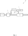
- FIG. 1 is a schematic diagram illustrating the outline of a fluid control device according to a first embodiment of the present invention
- FIG. 2 is a schematic block diagram illustrating the outline of control by the fluid control device of the first embodiment
- FIG. 3 is a schematic diagram illustrating the details of the fluid control device of the first embodiment
- FIG. 4 is a schematic graph illustrating the relationship between a characteristic map and characteristic functions in the fluid control device of the first embodiment.
- FIG. 5 is a schematic diagram illustrating a flow rate ratio control device according to a second embodiment of the present invention.
- a fluid control device 100 according to a first embodiment of the present invention will be described with reference to FIGS. 1 to 4 .
- the fluid control device 100 of the first embodiment is, for example, one used to supply gas as fluid to a chamber or the like in a semiconductor manufacturing process.
- the gas used here is one of a type that must not be leaked outside from a pipe and the like forming a flow path for various reasons such as being toxic to human bodies and being ignitable.
- a hardware portion constituting the fluid control device 100 of the first embodiment is provided between a first mass flow controller MFC 1 serving as a gas supply source and a chamber present on the lowermost side in the flow path.
- the fluid control device 100 is one that, in the flow path, includes: a second mass flow controller MFC 2 provided on the downstream side of the first mass flow controller MFC 1 ; a pressure sensor P provided between the first mass flow controller MFC 1 and the second mass flow controller MFC 2 ; and a controller C that inputs a set flow rate to the second mass flow controller MFC 2 on the basis of a measured pressure measured by the pressure sensor P.
- the first mass flow controller MFC 1 does not constitute the fluid control device 100 of the first embodiment.
- the flow path between the first mass flow controller MFC 1 and the second mass flow controller MFC 2 has volume, and therefore a gas reservoir G having a predetermined volume as illustrated typified by FIG. 1 is formed.
- the pressure sensor P is one that measures the pressure of the gas reservoir G.
- the pressure of the gas reservoir G is determined by the difference between the flow rate Q in of the gas flowing from the first mass flow controller MFC 1 into the gas reservoir G and a flow rate output Q out obtained by the second mass flow controller MFC 2 .
- the pressure of the gas reservoir G is measured by the pressure sensor P, and inputted to the controller C as a pressure signal indicating the measured pressure P 0 .
- the controller C inputs the set flow rate Q set corresponding to the value of the measured pressure P 0 to the second mass flow controller MFC 2 .
- the second mass flow controller MFC 2 outputs the flow rate output Q out corresponding to the set flow rate Q set .
- the controller C is one that appropriately changes the set flow rate to be set in the second mass flow controller MFC 2 , and controls the flow rate output Q out obtained by the second mass flow controller MFC 2 so that the pressure of the gas reservoir G measured by the pressure sensor P is suppressed to a value lower than a limit pressure.
- the set flow rate Q set is controlled so that the convergence time required for the deviation between the set flow rate Q set and the flow rate output Q out to converge to a tolerance becomes equal to or less than a predetermined time.
- the second mass flow controller MFC 2 is one including: a body 1 attached to the flow path and formed with an internal flow path; a flow rate sensor 2 and valve 3 attached to the body 1 ; a cover 4 attached to the body 1 so as to cover the flow rate sensor 2 and the valve 3 ; and a control board B provided inside the cover 4 to perform flow rate feedback control of the opening level of the valve 3 . That is, the mass flow controller is one in which the various components for performing flow rate control are packaged.
- the flow rate sensor 2 is a thermal type flow rate sensor, and configured to include: a flow dividing element 21 provided in the flow path; a narrow tube 22 that branches from the upstream side of the flow dividing element 21 and merges with the downstream side of the flow dividing element 21 ; two electric heating coils 23 that are wound on the narrow tube 22 and respectively applied with voltages so as to be kept at constant temperatures; a detection circuit 24 that detects the difference between the voltages applied to the respective electric heating coils 23 ; and flow rate calculation part 25 that, on the basis of the output of the detection circuit 24 , calculates the flow rate of the gas flowing through the flow path.
- the valve 3 is, for example, a piezo valve 3 , and the opening level thereof is controlled by applied voltage.
- the control board B is a computer including a CPU, a memory, an A/D converter, a D/A converter, and various input/output means, and the functions thereof as a controller are implemented by executing a mass flow controller program stored in the memory to cooperate with various devices. That is, the control board B fulfills at least functions as the above-described flow rate calculation part 25 and a valve control part 5 .
- the valve control part 5 controls the opening level of the valve 3 on the basis of the set flow rate inputted from outside and the measured flow rate measured by the flow rate sensor 2 . More specifically, the valve control part 5 changes the applied voltage to the valve 3 to change the opening level of the valve 3 so that the deviation between the set flow rate and the measured flow rate decreases.
- the set flow rate is set to a value outputted from the controller C.
- the second mass flow controller MFC 2 is formed with a flow rate feedback system and forms a minor loop in the fluid control device 100 .
- the controller C is configured as a separate body from the second mass flow controller MFC 2 , and the functions thereof are implemented by a computer including a CPU, a memory, an A/D converter, a D/A converter, and various input/output means.
- the controller C fulfills at least a function as a set flow rate generator 6 by executing a program stored in the memory to make various devices cooperate.
- the set flow rate generator 6 is inputted with the measured pressure measured by the pressure sensor P and outputs the set flow rate corresponding to the measured pressure to the valve control part 5 of the second mass flow controller MFC 2 . More specifically, the set flow rate generator 6 refers to a pressure-flow rate map in which set flow rates corresponding to measured pressure values are provided, and outputs the set flow rate corresponding to the measured pressure measured by the pressure sensor P.
- the set flow rate generator 6 includes: a map storage part 61 that stores the pressure-flow rate map; and a set flow rate determination part 62 that, on the basis of the measured pressure and the pressure-flow rate map, determining the set flow rate to be set in the second mass flow controller MFC 2 .
- the pressure-flow rate map is a one-dimensional map that when some measured pressure value is measured by the pressure sensor P, provides a set flow rate value capable of simultaneously satisfying multiple control conditions.
- set flow rates corresponding to respective measured pressures are experimentally obtained and determined so as to simultaneously satisfy four control conditions.
- the four control conditions are: (a) the pressure of the gas reservoir G must be equal to or less than the limit pressure, (b) the valve 3 must be fully closed, and after the start of flow rate control at the set flow rate in a state where the flow rate output of the second mass flow controller MFC 2 is zero, the convergence time required for the deviation between the set flow rate and the measured flow rate corresponding to the flow rate output to converge within the tolerance must be able to be made equal to or less than the predetermined value, (c) a set flow rate corresponding to a measured pressure value must have a value not exceeding the maximum conductance of the valve 3 , and (d) pressure at which the operation of the thermal type flow rate sensor is ensured must be kept in the second mass flow controller MFC 2 .
- the limit pressure set upon request for safety is set to, for example, 400 Torr that is a lower value than atmospheric pressure.
- the tolerance stipulated from the flow rate control requirement specification is ⁇ 2% of the set flow rate, and the convergence time is set to, for example, 1 sec.
- the pressure-flow rate map is created by obtaining set flow rate values corresponding to multiple measured pressure values as pairs through experiment or simulation so as to simultaneously satisfy these control conditions (a) to (d) as described above.
- the pressure-flow rate map may be in a table format consisting of pairs of a measured pressure and a set flow rate, or may be, for example, a function having a measured pressure as input variable and a set flow rate as an output variable.
- the pressure-flow rate map graph plotted in the pressure-flow rate plane is set so as to be included a region surrounded by a limit pressure function indicating the limit pressure, a lowest operation pressure function indicating the lowest operation pressure at which the flow rate sensor 2 is operable, a maximum conductance function indicating the maximum conductance of the valve 3 with respect to each pressure, and a supply upper limit function indicating the maximum supply flow rate of the first mass flow controller MFC 1 .
- the fluid control device 100 of the first embodiment configured as described above can set, on the basis of the pressure-flow rate map, the set flow rate capable of satisfying the multiple control conditions in the second mass flow controller MFC 2 depending on the measured pressure that is the pressure of the gas reservoir G formed on the upstream side of the second mass flow controller MFC 2 .
- the measured pressure measured by the pressure sensor P varies depending on the difference between the inflow flow rate of the gas flowing from the first mass flow controller MFC 1 into the gas reservoir G and the outflow flow rate of the gas obtained by the second mass flow controller MFC 2 .
- the set flow rate corresponding to the varied pressure of the gas reservoir G is appropriately changed on the basis of the pressure-flow rate map every period by the set flow rate generator 6 of the controller C. For this reason, even when the pressure of the gas reservoir G varies, every time the control loop illustrated in FIG. 2 is repeated, an appropriate set flow rate is selected, and therefore the control accuracy of pressure and flow rate is increased.
- the pressure of the gas reservoir G is kept constant at a predetermined pressure by a pressure regulator as conventional, but that the pressure of the gas reservoir G can be varied and kept at various values that are equal to or more than the operable pressure of the flow rate sensor 2 and equal to or less than the limit pressure.
- a pressure regulator since a pressure regulator is not present, even when a gas species is changed, the change can be made difficult to affect the variation of the valve 3 of the second mass flow controller MFC 2 .
- the convergence time of the flow rate output of the second mass flow controller MFC 2 can be set to a short period of time like one second or less, which is the predetermined time.
- the flow rate ratio control device 200 of the second embodiment is one that controls the flow rate ratio of fluid flowing through branch flow paths L 1 and L 2 branching from the end of a supply gas flow path S 1 on an upstream side, as well as controls pressure on the upstream side in the supply gas flow path S 1 to a limit pressure or less.
- the flow rate ratio control device 200 includes: mass flow controllers MFC respectively provided in the branch flow paths L 1 and L 2 ; a controller C that sets set flow rates in the respective mass flow controllers MFC; and a pressure sensor P provided in the supply gas flow path S 1 or on the upstream side of the respective mass flow controllers MFC.
- mass flow controller provided on the upper side of FIG. 5 is also referred to as MFCA
- the branch flow path provided with MFCA as a first branch flow path L 1
- MFCB mass flow controller provided on the lower side of FIG. 5
- the branch flow path provided with MFCB as a second branch flow path L 2 .
- the pressure sensor P, MFCA, and a map storage part 61 and set flow rate determination part 62 of a set flow rate generator 6 have substantially the same configurations as those in the fluid control device 100 described in the first embodiment. That is, on the basis of a measured pressure measured by the pressure sensor P and a pressure-flow rate map, the set flow rate generator 6 changes the set flow rates to be set in valve control parts 5 of MFCA and MFCB so that pressures on the upstream sides of MFCA and MFCB becomes equal to a limit pressure and also the convergence time required for the total flow rate, which is the sum of flow rates respectively supplied from the first branch flow path L 1 and the second branch flow path L 2 , to converge to a target value becomes equal to or less than a predetermined time.
- the set flow rate generator 6 includes: the map storage part 61 that stores the pressure-flow rate map; a target total flow rate determination part 63 that determined the target total flow rate of the gas to be supplied to the controller C from the respective branch flow paths L 1 and L 2 ; and a flow rate distribution part 64 that, on the basis of the determined target total flow rate and a target flow rate ratio set by a user, determines the set flow rates to be set in the respective mass flow controllers.
- the pressure-flow rate map provides the relationship between pressure and the flow rate of the gas flowing through the one flow path; however, in the second embodiment, the pressure-flow rate map is one providing the relationship between a measured pressure on the upstream side of the respective mass flow controllers and the target total flow rate that is the target value of the sum of the flow rates of the fluid flowing through the respective branch flow paths L 1 and L 2 . That is, a measured pressure measured by the pressure sensor P, and a target total flow rate allowing the measured pressure to be suppressed to the limit pressure or less are stored as a pair.
- an idea of a region including pairs of a measured flow rate and a target total flow rate is the same as that in the first embodiment, and therefore description thereof is omitted.
- the target total flow rate determination part 63 refers to such a pressure-flow rate map on the basis of a measured pressure measured at the time, and determines the target total flow rate.
- the flow rate distribution part 64 calculates, on the basis of the target total flow rate and the target flow rate ratio, the set flow rates to be set in the respective mass flow controllers, and inputs the calculated values to the respective mass flow controllers.
- the target total flow rate corresponding to the measured pressure at the time is changed every control period, and further the set flow rates to be set in the respective mass flow controllers are also changed.
- the flow rate ratio of the fluid flowing through the respective branch flow path L 1 and L 2 is controlled to become equal to the target flow rate ratio, and also the upstream side of the respective mass flow controllers can be brought into a lower pressure state than the limit pressure.
- the fluid control device is not limited to one obtained by combining the pressure sensor and the mass flow controller, but may be configured by providing a valve and a flow rate sensor as single bodies in place of the mass flow controller.
- control board and the controller may be configured to be integrated into one computer to perform various types of calculation and control.
- the flow rate sensor is not limited to the thermal type flow rate sensor but may be a pressure type flow rate sensor. Also, a position where the flow rate sensor is provided may be on any of the upstream and downstream sides of the valve.
- the limit pressure and the convergence time may be appropriately set to various values depending on required specifications or the like.
- an example of setting the pressure-flow rate map is not limited to one described in the embodiment. A set pressure corresponding to a measured pressure is only required to be set so as to be included in a region determined by respective control conditions.
- the flow rate ratio control device described in the second embodiment may be one such that the respective mass flow controllers are provided with pressure sensors. Also, one mass flow controller may be one provided with functions as the set flow rate generator and the flow rate distribution part. That is, the controller described in the second embodiment is not provided as a separate body from the mass flow controllers, but may be integrated with a mass flow controller.
Landscapes
- Engineering & Computer Science (AREA)
- General Engineering & Computer Science (AREA)
- Physics & Mathematics (AREA)
- General Physics & Mathematics (AREA)
- Automation & Control Theory (AREA)
- Mechanical Engineering (AREA)
- Manufacturing & Machinery (AREA)
- Computer Hardware Design (AREA)
- Microelectronics & Electronic Packaging (AREA)
- Power Engineering (AREA)
- Condensed Matter Physics & Semiconductors (AREA)
- Fluid Mechanics (AREA)
- Flow Control (AREA)
Applications Claiming Priority (2)
| Application Number | Priority Date | Filing Date | Title |
|---|---|---|---|
| JP2018-096639 | 2018-05-18 | ||
| JP2018096639A JP7044629B2 (ja) | 2018-05-18 | 2018-05-18 | 流体制御装置、及び、流量比率制御装置 |
Publications (2)
| Publication Number | Publication Date |
|---|---|
| US20190354120A1 US20190354120A1 (en) | 2019-11-21 |
| US10705545B2 true US10705545B2 (en) | 2020-07-07 |
Family
ID=68533661
Family Applications (1)
| Application Number | Title | Priority Date | Filing Date |
|---|---|---|---|
| US16/413,312 Active US10705545B2 (en) | 2018-05-18 | 2019-05-15 | Fluid control device and flow rate ratio control device |
Country Status (3)
| Country | Link |
|---|---|
| US (1) | US10705545B2 (ko) |
| JP (1) | JP7044629B2 (ko) |
| KR (1) | KR102615958B1 (ko) |
Families Citing this family (8)
| Publication number | Priority date | Publication date | Assignee | Title |
|---|---|---|---|---|
| JP7068062B2 (ja) * | 2018-06-18 | 2022-05-16 | 株式会社堀場製作所 | 流体制御装置、及び、流量比率制御装置 |
| IL269235A (en) * | 2019-09-09 | 2021-03-25 | Sherlock Leaks & Floods Ltd | Multi-range flowmeter |
| EP3848579B1 (de) * | 2020-01-13 | 2023-08-02 | Promix Solutions AG | System und verfahren zur dosierung eines flüssigen oder gasförmigen mediums |
| JP2021152786A (ja) * | 2020-03-24 | 2021-09-30 | 株式会社フジキン | 流量制御システム、流量制御システムの制御方法、流量制御システムの制御プログラム |
| JP7398306B2 (ja) * | 2020-03-24 | 2023-12-14 | 東京エレクトロン株式会社 | ガス検査方法、基板処理方法及び基板処理システム |
| WO2021240412A1 (en) * | 2020-05-26 | 2021-12-02 | Padmini Vna Mechatronics Pvt. Ltd. | Process for controlling flow characteristic of electromechanical valve |
| KR102445304B1 (ko) | 2020-09-18 | 2022-09-20 | 엠케이피 주식회사 | 유량 비율 제어 장치 |
| CN116677785B (zh) * | 2023-08-03 | 2023-10-20 | 山东中力高压阀门股份有限公司 | 一种组合式高温高压阀门 |
Citations (20)
| Publication number | Priority date | Publication date | Assignee | Title |
|---|---|---|---|---|
| US4052003A (en) * | 1976-08-06 | 1977-10-04 | Dickey-John Corporation | Liquid spreader control system |
| US4126540A (en) * | 1973-08-03 | 1978-11-21 | Atlantic Richfield Company | Apparatus and process for distributing a mixed phase through solids |
| US4392611A (en) * | 1981-05-15 | 1983-07-12 | Dickey-John Corporation | Sprayer control system |
| US5158714A (en) * | 1991-05-30 | 1992-10-27 | Union Oil Company Of California | Vapor-liquid distribution method and apparatus |
| US5394755A (en) * | 1992-09-30 | 1995-03-07 | Ckd Corporation | Flow quantity test system for mass flow controller |
| US5687092A (en) * | 1995-05-05 | 1997-11-11 | Nordson Corporation | Method of compensating for changes in flow characteristics of a dispensed fluid |
| US5942163A (en) * | 1997-06-03 | 1999-08-24 | Armstrong International, Inc. | Low pressure jacketed steam manifold |
| US6302106B1 (en) * | 1997-07-18 | 2001-10-16 | John E. Lewis | Rebreather system with optimal PO2 determination |
| US20030130807A1 (en) * | 2002-01-04 | 2003-07-10 | Jesse Ambrosina | Mass flow ratio system and method |
| US20050005994A1 (en) * | 2002-06-03 | 2005-01-13 | Kazuhiko Sugiyama | Method for supplying gas while dividing to chamber from gas supply facility equipped with flow controller |
| WO2008072614A1 (ja) | 2006-12-12 | 2008-06-19 | Horiba Stec, Co., Ltd. | 流量比率制御装置 |
| US20100163119A1 (en) * | 2008-12-25 | 2010-07-01 | Horiba Stec, Co., Ltd. | Mass flow meter and mass flow controller |
| US20110094596A1 (en) * | 2003-06-20 | 2011-04-28 | Fujikin Incorporated | Apparatus and method of dividing and supplying gas to a chamber from a gas supply apparatus equipped with flow-rate control system |
| US20110106319A1 (en) * | 2009-11-05 | 2011-05-05 | Horiba Stec, Co., Ltd. | Mass flow controller |
| US8015995B2 (en) * | 2004-02-12 | 2011-09-13 | Entegris, Inc. | System and method for flow monitoring and control |
| US8517353B2 (en) * | 2010-09-27 | 2013-08-27 | Uop Llc | Apparatus and process for distributing vapor and liquid phases |
| US20140182692A1 (en) * | 2011-05-10 | 2014-07-03 | Fujikin Incorporated | Pressure type flow control system with flow monitoring |
| US8944095B2 (en) * | 2010-04-30 | 2015-02-03 | Tokyo Electron Limited | Gas supply apparatus for semiconductor manufacturing apparatus |
| US20160079105A1 (en) * | 2014-09-12 | 2016-03-17 | Vijay D. Parkhe | Increasing the gas efficiency for an electrostatic chuck |
| US9477232B2 (en) * | 2013-08-30 | 2016-10-25 | Fujikin Incorporated | Apparatus for dividing and supplying gas and method for dividing and supplying gas |
Family Cites Families (6)
| Publication number | Priority date | Publication date | Assignee | Title |
|---|---|---|---|---|
| KR100627959B1 (ko) * | 2004-12-30 | 2006-09-25 | 동부일렉트로닉스 주식회사 | 매스 플로우 미터 |
| KR20080017117A (ko) * | 2006-08-21 | 2008-02-26 | 삼성전자주식회사 | 매스 플로우 콘트롤러 |
| JP5499381B2 (ja) * | 2009-10-20 | 2014-05-21 | 日立金属株式会社 | 流量制御装置 |
| US9304518B2 (en) | 2011-08-24 | 2016-04-05 | Bio-Rad Laboratories, Inc. | Modular automated chromatography system |
| JP6415889B2 (ja) * | 2014-08-01 | 2018-10-31 | 株式会社堀場エステック | 流量制御装置、流量制御装置用プログラム、及び、流量制御方法 |
| JP6804874B2 (ja) * | 2016-05-31 | 2020-12-23 | 株式会社堀場エステック | 流量制御装置、流量制御装置に用いられるプログラム、及び、流量制御方法 |
-
2018
- 2018-05-18 JP JP2018096639A patent/JP7044629B2/ja active Active
-
2019
- 2019-05-15 US US16/413,312 patent/US10705545B2/en active Active
- 2019-05-17 KR KR1020190057660A patent/KR102615958B1/ko active IP Right Grant
Patent Citations (21)
| Publication number | Priority date | Publication date | Assignee | Title |
|---|---|---|---|---|
| US4126540A (en) * | 1973-08-03 | 1978-11-21 | Atlantic Richfield Company | Apparatus and process for distributing a mixed phase through solids |
| US4052003A (en) * | 1976-08-06 | 1977-10-04 | Dickey-John Corporation | Liquid spreader control system |
| US4392611A (en) * | 1981-05-15 | 1983-07-12 | Dickey-John Corporation | Sprayer control system |
| US5158714A (en) * | 1991-05-30 | 1992-10-27 | Union Oil Company Of California | Vapor-liquid distribution method and apparatus |
| US5394755A (en) * | 1992-09-30 | 1995-03-07 | Ckd Corporation | Flow quantity test system for mass flow controller |
| US5687092A (en) * | 1995-05-05 | 1997-11-11 | Nordson Corporation | Method of compensating for changes in flow characteristics of a dispensed fluid |
| US5942163A (en) * | 1997-06-03 | 1999-08-24 | Armstrong International, Inc. | Low pressure jacketed steam manifold |
| US6302106B1 (en) * | 1997-07-18 | 2001-10-16 | John E. Lewis | Rebreather system with optimal PO2 determination |
| US20030130807A1 (en) * | 2002-01-04 | 2003-07-10 | Jesse Ambrosina | Mass flow ratio system and method |
| US20050005994A1 (en) * | 2002-06-03 | 2005-01-13 | Kazuhiko Sugiyama | Method for supplying gas while dividing to chamber from gas supply facility equipped with flow controller |
| US20110094596A1 (en) * | 2003-06-20 | 2011-04-28 | Fujikin Incorporated | Apparatus and method of dividing and supplying gas to a chamber from a gas supply apparatus equipped with flow-rate control system |
| US8015995B2 (en) * | 2004-02-12 | 2011-09-13 | Entegris, Inc. | System and method for flow monitoring and control |
| US20100030390A1 (en) * | 2006-12-12 | 2010-02-04 | Horiba Stec, Co., Ltd. | Flow rate ratio control device |
| WO2008072614A1 (ja) | 2006-12-12 | 2008-06-19 | Horiba Stec, Co., Ltd. | 流量比率制御装置 |
| US20100163119A1 (en) * | 2008-12-25 | 2010-07-01 | Horiba Stec, Co., Ltd. | Mass flow meter and mass flow controller |
| US20110106319A1 (en) * | 2009-11-05 | 2011-05-05 | Horiba Stec, Co., Ltd. | Mass flow controller |
| US8944095B2 (en) * | 2010-04-30 | 2015-02-03 | Tokyo Electron Limited | Gas supply apparatus for semiconductor manufacturing apparatus |
| US8517353B2 (en) * | 2010-09-27 | 2013-08-27 | Uop Llc | Apparatus and process for distributing vapor and liquid phases |
| US20140182692A1 (en) * | 2011-05-10 | 2014-07-03 | Fujikin Incorporated | Pressure type flow control system with flow monitoring |
| US9477232B2 (en) * | 2013-08-30 | 2016-10-25 | Fujikin Incorporated | Apparatus for dividing and supplying gas and method for dividing and supplying gas |
| US20160079105A1 (en) * | 2014-09-12 | 2016-03-17 | Vijay D. Parkhe | Increasing the gas efficiency for an electrostatic chuck |
Also Published As
| Publication number | Publication date |
|---|---|
| US20190354120A1 (en) | 2019-11-21 |
| KR20190132267A (ko) | 2019-11-27 |
| KR102615958B1 (ko) | 2023-12-21 |
| JP2019200748A (ja) | 2019-11-21 |
| JP7044629B2 (ja) | 2022-03-30 |
Similar Documents
| Publication | Publication Date | Title |
|---|---|---|
| US10705545B2 (en) | Fluid control device and flow rate ratio control device | |
| US10921828B2 (en) | Fluid control apparatus and flow rate ratio control apparatus | |
| US10969259B2 (en) | Flow rate control device, method of calibrating flow rate of flow rate control device, flow rate measuring device, and method of measuring flow rate using flow rate measuring device | |
| KR102384035B1 (ko) | 유량 제어 장치, 유량 제어 장치용 프로그램을 기억한 기억 매체 및 유량 제어 방법 | |
| US20210223797A1 (en) | Systems and Methods for Flow Sensor Back Pressure Adjustment for Mass Flow Controller | |
| KR102639507B1 (ko) | 액체 재료 기화 공급 장치 및 제어 프로그램 | |
| US10996689B2 (en) | Flow rate ratio control device with flow velocity control mode | |
| KR20120049148A (ko) | 매스 플로우 컨트롤러 및 유량 제어 프로그램이 저장된 저장 매체 | |
| TWI723170B (zh) | 流量控制裝置、用於流量控制裝置的程式與流量控制方法 | |
| US20170370763A1 (en) | Methods, systems, and apparatus for mass flow verification based on choked flow | |
| JPWO2020004183A1 (ja) | 流量制御方法および流量制御装置 | |
| US10316835B2 (en) | Method of determining output flow rate of gas output by flow rate controller of substrate processing apparatus | |
| KR102596165B1 (ko) | 질량 유량 제어 시스템 및 당해 시스템을 포함하는 반도체 제조 장치 및 기화기 | |
| JP2020013269A (ja) | 流量制御装置 | |
| US20140319705A1 (en) | Vapor concentration control system, vapor concentration control device and control program | |
| US11326914B2 (en) | Flow rate measurement apparatus and method for more accurately measuring gas flow to a substrate processing system | |
| US20220228896A1 (en) | Pressure control system, pressure control method, and pressure control program | |
| JP5973364B2 (ja) | 液体供給制御装置、及び液体供給システム |
Legal Events
| Date | Code | Title | Description |
|---|---|---|---|
| AS | Assignment |
Owner name: HORIBA STEC, CO., LTD., JAPAN Free format text: ASSIGNMENT OF ASSIGNORS INTEREST;ASSIGNORS:TAKIJIRI, KOTARO;KANAMARU, YUSUKE;NAKAGAWA, EMIKO;AND OTHERS;REEL/FRAME:049188/0475 Effective date: 20190422 |
|
| FEPP | Fee payment procedure |
Free format text: ENTITY STATUS SET TO UNDISCOUNTED (ORIGINAL EVENT CODE: BIG.); ENTITY STATUS OF PATENT OWNER: LARGE ENTITY |
|
| STPP | Information on status: patent application and granting procedure in general |
Free format text: DOCKETED NEW CASE - READY FOR EXAMINATION |
|
| STPP | Information on status: patent application and granting procedure in general |
Free format text: NOTICE OF ALLOWANCE MAILED -- APPLICATION RECEIVED IN OFFICE OF PUBLICATIONS |
|
| STPP | Information on status: patent application and granting procedure in general |
Free format text: PUBLICATIONS -- ISSUE FEE PAYMENT VERIFIED |
|
| STCF | Information on status: patent grant |
Free format text: PATENTED CASE |
|
| MAFP | Maintenance fee payment |
Free format text: PAYMENT OF MAINTENANCE FEE, 4TH YEAR, LARGE ENTITY (ORIGINAL EVENT CODE: M1551); ENTITY STATUS OF PATENT OWNER: LARGE ENTITY Year of fee payment: 4 |