US1069283A - Flexible shaft. - Google Patents
Flexible shaft. Download PDFInfo
- Publication number
- US1069283A US1069283A US73192012A US1912731920A US1069283A US 1069283 A US1069283 A US 1069283A US 73192012 A US73192012 A US 73192012A US 1912731920 A US1912731920 A US 1912731920A US 1069283 A US1069283 A US 1069283A
- Authority
- US
- United States
- Prior art keywords
- tongue
- link
- flexible shaft
- blank
- bent
- Prior art date
- Legal status (The legal status is an assumption and is not a legal conclusion. Google has not performed a legal analysis and makes no representation as to the accuracy of the status listed.)
- Expired - Lifetime
Links
Images
Classifications
-
- F—MECHANICAL ENGINEERING; LIGHTING; HEATING; WEAPONS; BLASTING
- F16—ENGINEERING ELEMENTS AND UNITS; GENERAL MEASURES FOR PRODUCING AND MAINTAINING EFFECTIVE FUNCTIONING OF MACHINES OR INSTALLATIONS; THERMAL INSULATION IN GENERAL
- F16C—SHAFTS; FLEXIBLE SHAFTS; ELEMENTS OR CRANKSHAFT MECHANISMS; ROTARY BODIES OTHER THAN GEARING ELEMENTS; BEARINGS
- F16C1/00—Flexible shafts; Mechanical means for transmitting movement in a flexible sheathing
- F16C1/02—Flexible shafts; Mechanical means for transmitting movement in a flexible sheathing for conveying rotary movements
- F16C1/04—Articulated shafts
Definitions
- My invention relates to flexible shafts and consists in the improvements hereinafter described and pointed out in the claims.
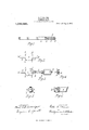
- FIG. l is a side elevation of two adjacent links of a shaft embodying my invention.
- Fig. 2 shows the blank out of which the link is formed.
- Fig. 3 shows the links partly formed and interlocked.
- Fig. 4: is an elevation looking from the right of Fig. 3.
- Fig. 5, is an end view of one link.
- Fig. 6, is perspective view of a portion of one
- the shaft embodying my invention is formed of a series of interlocked links A, each of which is constructed from a blank stamped out of thin malleable metal.
- the thin metal is first stamped out in the form shown in F 2 in which the body a is nearly square, but the edges at each corner are cut in as shown at Z Z d d and from the center of each side there extends a tongue B, the end b of which is formed in the are of a circle of larger diameter than the width of the tongue.
- These tongues are then bent to form the sides of a parallelogram as shown in the middle link in Fig. 3, the enlarged portion b touching and extending at right angles to the body a.
- the tongues of adjacent links are interlocked as indicated in Fig. 3 and then the end of the tongue is again bent downward touching the main body a of the blank.
- the body ct of the blank is then bent over into a cylindrical form, its inner surface lying against the peripheries of the parts Z9 and its edges coming together as shown at C in Fig. 1.
- the cut portions Z Z upon each side of the body a of the blank come opposite each other and form a slot or indentation into and through which the tongue B extends. This is indicated at D D Fig. l.
- the tongue B is inclosed and held from deformation by the body a of the link A.
- the slot C acting to prevent lat-eral motion of the tongue and the enlarged portion inclosed by the turned-up metal of the body a prevents the tongue from being drawn out of such inclosure or being bent in the other direction.
- Vhat I claim is:-
- a link A having a tongue B extending from one side thereof, said tongue having an enlargement at its outer end, said tongue being bent over upon itself and the body of said link being bent over to inclose the enlarged end of said tongue.
- a link formed of a body of thin metal having its corners cut out, said body being bent over upon itself to an approximately cylindrical form so that the cut out portions form a slot in the end of said link, a tongue extending from one side of the body of said link being bent over passing through said slot, said tongue being provided with an enlarged end inclosed by the body of the link.
Landscapes
- Engineering & Computer Science (AREA)
- General Engineering & Computer Science (AREA)
- Health & Medical Sciences (AREA)
- Oral & Maxillofacial Surgery (AREA)
- Mechanical Engineering (AREA)
- Adornments (AREA)
Description
E. C. OLIVER.V
FLEXIBLE SHAFT.
APPLIOATION FILED N0v.1s.1912.
,069,283. Patent@ Aug. 5, 1913.
w/T/v/SSES /NVENTOR cw Ww ATTORNEY coLumum PLANoanAPn co.,w^sH1Nm-0N c.
EDD C. OLIVER, OF DETROIT, MICHIGAN.
FLEXIBLE SHAFT. .s
Specicaton of Letters Patent.
Patented Aug. 5,1913.
Application iiled November 18, 1912. Serial No. 731,920.
To all 'whom t may concern:
Be it known that I, EDD C. OLIVER, a citizen of the United States, residing at Detroit, county of Wayne, State of Michigan, have invented a certain new and useful Improvement in Flexible Shafts, and declare the following to be a full, clear, and exact description of the same, such as will enable others skilled in the art to which it pertains to make and use the same, reference being had to the accompanying drawings, which form a part of this specication.
My invention relates to flexible shafts and consists in the improvements hereinafter described and pointed out in the claims.
In the accompanying drawings Figure l, is a side elevation of two adjacent links of a shaft embodying my invention. Fig. 2, shows the blank out of which the link is formed. Fig. 3, shows the links partly formed and interlocked. Fig. 4:, is an elevation looking from the right of Fig. 3. Fig. 5, is an end view of one link. Fig. 6, is perspective view of a portion of one The shaft embodying my invention is formed of a series of interlocked links A, each of which is constructed from a blank stamped out of thin malleable metal. The thin metal is first stamped out in the form shown in F 2 in which the body a is nearly square, but the edges at each corner are cut in as shown at Z Z d d and from the center of each side there extends a tongue B, the end b of which is formed in the are of a circle of larger diameter than the width of the tongue. These tongues are then bent to form the sides of a parallelogram as shown in the middle link in Fig. 3, the enlarged portion b touching and extending at right angles to the body a. After the second bend the tongues of adjacent links are interlocked as indicated in Fig. 3 and then the end of the tongue is again bent downward touching the main body a of the blank. The body ct of the blank is then bent over into a cylindrical form, its inner surface lying against the peripheries of the parts Z9 and its edges coming together as shown at C in Fig. 1. The cut portions Z Z upon each side of the body a of the blank come opposite each other and form a slot or indentation into and through which the tongue B extends. This is indicated at D D Fig. l. By this construction the tongue B is inclosed and held from deformation by the body a of the link A. The slot C acting to prevent lat-eral motion of the tongue and the enlarged portion inclosed by the turned-up metal of the body a prevents the tongue from being drawn out of such inclosure or being bent in the other direction.
Vhat I claim is:-
1. In a flexible shaft, a link A having a tongue B extending from one side thereof, said tongue having an enlargement at its outer end, said tongue being bent over upon itself and the body of said link being bent over to inclose the enlarged end of said tongue.
2. In a flexible shaft, a link formed of a body of thin metal having its corners cut out, said body being bent over upon itself to an approximately cylindrical form so that the cut out portions form a slot in the end of said link, a tongue extending from one side of the body of said link being bent over passing through said slot, said tongue being provided with an enlarged end inclosed by the body of the link.
In testimony whereof, I sign this specification in the presence of two witnesses.
EDD C. OLIVER.
Witnesses: VIRGINIA C. SPRATT,
ELLIOTT J. STODDARD.
Copies of this patent may be obtained for ve cents each, by addressing the Commissioner of Patents. Washington, D. C.
Priority Applications (1)
| Application Number | Priority Date | Filing Date | Title |
|---|---|---|---|
| US73192012A US1069283A (en) | 1912-11-18 | 1912-11-18 | Flexible shaft. |
Applications Claiming Priority (1)
| Application Number | Priority Date | Filing Date | Title |
|---|---|---|---|
| US73192012A US1069283A (en) | 1912-11-18 | 1912-11-18 | Flexible shaft. |
Publications (1)
| Publication Number | Publication Date |
|---|---|
| US1069283A true US1069283A (en) | 1913-08-05 |
Family
ID=3137520
Family Applications (1)
| Application Number | Title | Priority Date | Filing Date |
|---|---|---|---|
| US73192012A Expired - Lifetime US1069283A (en) | 1912-11-18 | 1912-11-18 | Flexible shaft. |
Country Status (1)
| Country | Link |
|---|---|
| US (1) | US1069283A (en) |
-
1912
- 1912-11-18 US US73192012A patent/US1069283A/en not_active Expired - Lifetime
Similar Documents
| Publication | Publication Date | Title |
|---|---|---|
| US749834A (en) | Half to richard f | |
| US479999A (en) | Corrugated packing | |
| US453797A (en) | Billiard-cue attachment | |
| US1069283A (en) | Flexible shaft. | |
| US769366A (en) | Flexible tube. | |
| US752512A (en) | Belt-joint | |
| US465612A (en) | vinson | |
| US821141A (en) | Lens-finder for clinical thermometers. | |
| US879268A (en) | Shelf-grating for stoves, &c. | |
| US874249A (en) | Chimney cap or ventilator. | |
| US1345136A (en) | Means for holding slats to belts | |
| US910014A (en) | Flexible shaft. | |
| US598643A (en) | Cuff-button | |
| US458319A (en) | Device for repairing broken slats | |
| USD45895S (en) | Design for a metal strip | |
| US1129968A (en) | Corrugated fastener. | |
| US1288030A (en) | Sheet-metal toy. | |
| USD29294S (en) | Design for a radiator-section | |
| US446557A (en) | Thomas y | |
| US281058A (en) | Hubebt c | |
| US781282A (en) | Lacing for shoes, &c. | |
| US1028310A (en) | Coupling-ring for refrigerator-linings. | |
| US794534A (en) | Sheet-metal damper. | |
| USD33104S (en) | Design for a chaffer or sieve slat | |
| USD35518S (en) | Design for a limb-prop bracket |