US10688323B2 - Safety device with fall arrest and descending modes - Google Patents
Safety device with fall arrest and descending modes Download PDFInfo
- Publication number
- US10688323B2 US10688323B2 US12/620,671 US62067109A US10688323B2 US 10688323 B2 US10688323 B2 US 10688323B2 US 62067109 A US62067109 A US 62067109A US 10688323 B2 US10688323 B2 US 10688323B2
- Authority
- US
- United States
- Prior art keywords
- housing
- brake assembly
- safety device
- operatively connected
- gear
- Prior art date
- Legal status (The legal status is an assumption and is not a legal conclusion. Google has not performed a legal analysis and makes no representation as to the accuracy of the status listed.)
- Active, expires
Links
- 230000000712 assembly Effects 0.000 claims abstract description 9
- 238000000429 assembly Methods 0.000 claims abstract description 9
- 239000012530 fluid Substances 0.000 claims description 3
- 230000013011 mating Effects 0.000 claims 2
- 238000007789 sealing Methods 0.000 claims 1
- 238000002955 isolation Methods 0.000 description 14
- 230000008878 coupling Effects 0.000 description 7
- 238000010168 coupling process Methods 0.000 description 7
- 238000005859 coupling reaction Methods 0.000 description 7
- 125000006850 spacer group Chemical group 0.000 description 7
- 239000000356 contaminant Substances 0.000 description 3
- 238000005192 partition Methods 0.000 description 2
- 230000001133 acceleration Effects 0.000 description 1
- 230000003247 decreasing effect Effects 0.000 description 1
- 238000004519 manufacturing process Methods 0.000 description 1
Images


Classifications
-
- A—HUMAN NECESSITIES
- A62—LIFE-SAVING; FIRE-FIGHTING
- A62B—DEVICES, APPARATUS OR METHODS FOR LIFE-SAVING
- A62B1/00—Devices for lowering persons from buildings or the like
- A62B1/06—Devices for lowering persons from buildings or the like by making use of rope-lowering devices
- A62B1/08—Devices for lowering persons from buildings or the like by making use of rope-lowering devices with brake mechanisms for the winches or pulleys
- A62B1/10—Devices for lowering persons from buildings or the like by making use of rope-lowering devices with brake mechanisms for the winches or pulleys mechanically operated
Definitions
- the present invention relates to a safety device with fall arrest and descending modes.
- Safety devices are well known in the art of fall protection safety equipment for use by workers performing tasks during which there is a risk a fall may occur.
- One type of safety device commonly used is a self-retracting lifeline, which is typically connected to a support structure within the vicinity the worker is performing the task, and the end of the cable is typically connected to a safety harness worn by the worker.
- Self-retracting lifelines generally include a housing containing a drum around which a cable, rope, or webbing is wound. The drum is spring biased to pay out cable as tension pulling the cable is applied and to retract any of the cable that has been unwound from the drum as the tension on the cable is reduced or released.
- the housing also includes a brake assembly for stopping rotation of the drum when the cable suddenly unwinds from the drum at a rate greater than a predetermined maximum angular velocity. As the rotation of the drum is stopped, additional cable is prevented from being paid out of the housing to stop the fall of the worker.
- a controlled descent device may be used to assist the worker to safety.
- a housing has a first cavity and a second cavity in fluid communication via a bore interconnecting the first and second cavities.
- a drum is rotatably operatively connected to the housing within the second cavity.
- a lifeline has an intermediate portion interconnecting a first end and a second end. The first end is operatively connected to the drum.
- a shaft is operatively connected to the drum in the second cavity and extends through the bore and into the first cavity.
- a first brake assembly is operatively connected to the shaft, and a second brake assembly is operatively connected to the shaft.
- a control is operatively connected to the first and second brake assemblies and has a first position and a second position. The first position selectively engages the first brake assembly and the second position selectively engages the second brake assembly.
- the first cavity is sealed.
- a drum is rotatably operatively connected to a housing.
- a lifeline has an intermediate portion interconnecting a first end and a second end. The first end is operatively connected to the drum.
- a first brake assembly is operatively connected to the drum, and a second brake assembly is operatively connected to the drum.
- a control is operatively connected to the first and second brake assemblies and has a first position and a second position. The first position selectively engages the first brake assembly and the second position selectively engages the second brake assembly.
- a drum is rotatably operatively connected to a housing.
- a lifeline has an intermediate portion interconnecting a first end and a second end. The first end is operatively connected to the drum, at least a portion of the intermediate portion is wound about the drum, and the second end is operatively connected to a hook.
- a first brake assembly and a second brake assembly are operatively connected to the drum.
- the first brake assembly includes a rotor to which at least one first pawl having a friction pad is pivotally operatively connected and a first spur gear.
- the rotor includes a rotor gear.
- the first spur gear includes inner teeth and outer teeth.
- the second brake assembly includes a gear assembly and at least one second pawl.
- the gear assembly includes a second spur gear.
- a shaft includes first and second teeth and operatively connects the first and second brake assemblies. The inner teeth of the first spur gear mate with the first teeth of the shaft and the outer teeth mate with the rotor gear to interconnect the shaft and the rotor.
- the second spur gear mates with the second teeth of the shaft.
- a control is operatively connected to the shaft and has a first position and a second position. The first position allows the shaft to rotate and selectively engages the first brake assembly in a descending mode in which the friction pad contacts the housing when the rotor rotates.
- the second position locks the shaft and selectively engages the second brake assembly in a fall arrest mode in which the at least one second pawl is operatively connected to the drum and is configured and arranged to engage the gear assembly when the drum rotates at a predetermined speed.
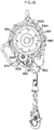
- FIG. 1 is a front perspective view of a safety device with fall arrest and descending modes constructed according to the principles of the present invention
- FIG. 2 is a rear view of the safety device shown in FIG. 1 ;
- FIG. 3 is a side view of the safety device shown in FIG. 1 ;
- FIG. 4 is an exploded perspective view of the safety device shown in FIG. 1 ;
- FIG. 5A is an exploded front perspective view of a control and descending assembly of the safety device shown in FIG. 1 ;
- FIG. 5B is an exploded rear perspective view of the control and descending assembly shown in FIG. 5A ;
- FIG. 6 is an exploded perspective view of a portion of a brake assembly of the safety device shown in FIG. 1 ;
- FIG. 7 is a front view of the safety device shown in FIG. 1 in a fall arrest mode
- FIG. 8 is a cross-section view of the safety device taken along the lines 8 - 8 in FIG. 7 ;
- FIG. 9 is a perspective view of the control and the descending assembly in the fall arrest mode
- FIG. 10 is a cross-section view of the control and the descending assembly in the fall arrest mode
- FIG. 11 is a front view of the safety device shown in FIG. 1 in a descending mode
- FIG. 12 is a cross-section view of the safety device taken along the lines 12 - 12 in FIG. 11 ;
- FIG. 13 is a perspective view of the control and the descending assembly in the descending mode
- FIG. 14 is a cross-section view of the control and the descending assembly in the descending mode
- FIG. 15 is an exploded perspective view of a first brake assembly of the control and descending assembly shown in FIGS. 5A and 5B ;
- FIG. 16 is a cross-section view of the first brake assembly taken proximate the rotation axis of the assembly shown in FIG. 15 ;
- FIG. 17 is a front perspective view of another embodiment safety device with fall arrest and descending modes constructed according to the principles of the present invention.
- FIG. 18 is a front view of the safety device shown in FIG. 17 with a front plate removed;
- FIG. 19 is a partial exploded perspective view of the safety device shown in FIG. 17 ;
- FIG. 20 is a front view of the safety device shown in FIG. 17 ;
- FIG. 21 is a cross-sectional view taken along the lines 21 - 21 in FIG. 20 ;
- FIG. 22 is a front view of the safety device shown in FIG. 17 ;
- FIG. 23 is a cross-sectional view taken along the lines 23 - 23 in FIG. 22 ;
- FIG. 24 is a front view of the safety device shown in FIG. 17 ;
- FIG. 25 is a cross-sectional view taken along the lines 25 - 25 in FIG. 24 .
- the safety device 100 includes a front housing portion 101 and a rear housing portion 121 that form a cavity in which some of the other components are housed.
- the front housing portion 101 includes a front plate 102 , which includes a protrusion 103 proximate the top, a center aperture 104 , a bottom opening 105 with apertures 106 proximate the sides and the bottom of the bottom opening 105 , and bottom apertures 107 below the bottom opening 105 .
- a top 108 , a first side 111 , a second side 112 , and a bottom 114 extend outward from the front plate 102 to form a cavity (not shown) therebetween.
- the top 108 includes a notch or an opening 110 providing access to a cavity (not shown) configured and arranged to receive a portion of a swivel eye 240 .
- the second side 112 includes a handle portion 113 proximate the middle and the bottom of the second side 112 .
- the bottom 114 includes a notch or an opening 116 providing access to a cavity 117 .
- the rear housing portion 121 includes a rear plate 122 , which includes a center aperture 124 and other apertures (not shown).
- a top 128 , a first side 131 , a second side 132 , and a bottom 134 extend outward from the rear plate 122 to form a cavity 137 .
- the top 128 includes a notch or an opening 130 providing access to a cavity 129 configured and arranged to receive a portion of the swivel eye 240 .
- the second side 132 includes a handle portion 133 proximate the middle and the bottom of the second side 132 .
- a partition 135 extending from the second side 132 to proximate the first side 131 with a gap between the partition 135 and the first side 131 .
- the bottom 134 includes a notch or an opening 136 providing access to a cavity 138 .
- a control and descending assembly 145 is operatively connected to the front plate 102 proximate the bottom opening 105 .
- the assembly 145 which is shown in FIGS. 5A and 5B , includes a housing 146 , which houses some of the other assembly components, and a control knob 148 operatively connected to the housing 146 .
- the housing 146 Proximate the bottom of the front side, the housing 146 includes a bore 147 with a flanged portion 147 a extending outward proximate the perimeter of the bore 147 .
- the bore 147 includes notches 280 , preferably spaced approximately ninety degrees apart. In the orientation shown in FIG.
- the top right notch 280 is deeper than the top left notch 280 , which allows the spline sleeve 155 to have an inward and an outward position or engagement relative to the housing 146 .
- the spline sleeve 155 is in the inward position when the position indicator 149 a is positioned proximate the top right notch 280 , and the spline sleeve 155 is in the outward position when the position indicator 149 a is positioned proximate the top left notch 280 .
- the spline sleeve 155 is in the inward position, it is engaged with the pinion gear 172 and locked.
- the rear side of the housing 146 includes a cavity 260 with sides 260 b .
- the side proximate the front of the housing 146 includes a receiver 260 a .
- Above the cavity 260 is a bore 261 with an aperture 262 on each side.
- the bore 147 extends through the housing 146 between the cavity 260 and the bottom of the housing 146 .
- the bottom of the housing 146 includes a bore 263 on each side of the bottom.
- the knob 148 includes a flange portion 149 , which preferably has a knurled outer surface and a position indicator 149 a , and a cylindrical portion 151 extending outward from the flange portion 149 . Bores 150 extend axially through the knob 148 .
- the cylindrical portion 151 is configured and arranged to house some of the components of the assembly 145 .
- a spline sleeve 155 is generally washer-shaped with tabs 155 b extending outward from the base portion 155 a .
- the tabs 155 b are configured and arranged to correspond with the notches 280 in the housing 146 .
- a bore 156 extends through the center of the base portion 155 a , and apertures 157 and 157 a are positioned around the bore 156 . Apertures 157 are on opposing sides of the bore 156 , and aperture 157 a is on a side of the bore 156 between apertures 157 .
- the surface of the base portion 155 a forming the bore 156 includes teeth 156 a .
- a spring 154 is positioned proximate the bore 156 , and a washer 153 and a spiral ring 152 are positioned between the spring 154 and the front plate portion of the knob 148 . The spring 154 exerts a biasing force against the spline sleeve 155 , which moves inwardly and outwardly relative to the housing 146 .
- Fasteners 158 extend through bores 150 of the knob 148 and into the two opposing apertures 157 of the spline sleeve 155 to connect the knob 148 and the spline sleeve.
- Fastener 159 extends through the aperture 157 a between the opposing apertures 157 and is configured and arranged to be received in the recessed portion 281 when the control and descending assembly 145 is in select positions relative to the housing 146 .
- the first brake assembly includes a rotor 162 , pawls 161 , and friction pads 160 , which fit within the cavity 260 .
- the rotor 162 includes a base from which pivot receivers 162 a extend on opposing sides of the base and to which a gear 162 b is operatively connected.
- the ends of the pivot receivers 162 a include relatively flat surfaces 162 d .
- a bore 162 c extends through the base and the gear 162 b .
- Each of the pawls 161 includes a pivot portion 161 a , which is configured and arranged to fit and pivot within the respective pivot receiver 162 a .
- Each pivot portion 161 a includes a flanged portion 161 e proximate one side of the pivot portion 161 a .
- Each of the pawls 161 also includes a free end 161 b and a pad receiver 161 c .
- the pad receiver 161 c is positioned on the outer surface of the pawl 161 between the pivot portion 161 a and the free end 161 b .
- the pad receiver 161 c is configured and arranged to receive a portion of a friction pad 160 .
- Each of the pawls 161 also includes a relatively flat surface 161 d proximate between the pivot portion 161 a and the pad receiver 161 c .
- An optional disk 264 could be positioned between the pawls 161 and the housing 146 to reduce the friction of the flanged portions 161 e on the housing 146 .
- the disk 264 is shown in FIGS. 15 and 16 but is not shown in FIGS. 5A and 5B .
- a groove pin 163 extends through the bore 162 c , and one end of the groove pin 163 fits within the receiver 260 a and the other end fits within the middle aperture 167 .
- a spur gear 164 includes teeth 164 a around its outer perimeter, an aperture 164 b , and teeth 164 c around the perimeter forming the aperture 164 b .
- a base plate 165 has a shape corresponding to the shape of the housing 146 and includes top apertures 166 and 166 a , a middle aperture 167 , a bore 168 with apertures 169 around the sides and bottom of the bore 168 , and bottom apertures 170 .
- Fasteners 171 extend through apertures 166 a and 170 into bores 261 and 263 to connect the base plate 165 to the housing 146 .
- a pinion gear 172 includes a shaft portion 173 to which first teeth 174 and second teeth 175 are operatively connected.
- the first teeth 174 are proximate one end and the second teeth 175 are proximate the middle of the shaft portion 173 .
- the second teeth 175 include a male portion 175 a , which extends outward with a smaller diameter from the second teeth 175 .
- the male portion 175 a is configured and arranged to mate with the teeth 164 c of the spur gear 164 .
- the ends of the shaft portion 173 preferably have a smaller diameter than the middle of the shaft portion 173 .
- the pinion gear 172 extends through the bore 168 of the base plate 165 , the aperture 164 b of the spur gear 164 , the bore 147 of the housing 146 , the bore 156 of the spline sleeve 155 , the bore of the spring 154 , the aperture of the washer 153 , and the aperture of the spiral ring 152 . Because the knob 148 is connected to the spline sleeve 155 , the knob 148 is connected to the pinion gear 172 via the spline sleeve 155 .
- the spring 154 Because the spring 154 is fixedly connected to the end of the shaft portion 173 proximate the first teeth 174 , the spring 154 exerts a biasing force against the spline sleeve 155 toward the housing 146 .
- the first teeth 174 mate with the teeth 156 a of the spline sleeve 155 , and the male portion 175 a of the second teeth 175 mate with the teeth 164 c of the spur gear 164 .
- the teeth 164 a of the spur gear 164 mate with the teeth of the gear 162 b.
- the pivot receivers 162 a receive the respective pivot portions 161 a of the pawls 161 , and the flanged portions 161 e are positioned proximate one side of the rotor 162 between the rotor 162 and the housing 146 .
- the flanged portions 161 e prevent the pivot portions 161 a from sliding out of the pivot receivers 162 from the opposite side of the rotor 162 .
- the gear assembly 180 Proximate the other, inner side of the front housing portion 101 is a gear assembly 180 , which is operatively connected to the second teeth 175 , which extends through the bottom opening 105 of the front housing portion 101 .
- the gear assembly 180 shown in FIG. 6 , includes a hub 184 , a spur gear 181 , a friction disk 188 , a ratchet disk 190 , a friction disk 193 , a spring disk 195 , and a lock nut 197 .
- the hub 184 includes a flange portion 185 and a cylindrical portion 186 extending outward from the flange portion 185 .
- a bore 187 extends longitudinally through the hub 184 .
- the spur gear 181 includes an aperture 182 and teeth 183 .
- the friction disk 188 includes an aperture 189 .
- the ratchet disk 190 includes an aperture 191 and teeth 192 .
- the friction disk 193 includes an aperture 194 .
- the spring disk 195 includes an aperture 196 .
- the lock nut 197 includes an aperture 198 .
- the cylindrical portion 186 extends through the aperture 182 of the spur gear 181 , the aperture 189 of the friction disk 188 , the aperture 191 of the ratchet disk 190 , the aperture 194 of the friction disk 193 , the aperture 196 of the spring disk 195 .
- the cylindrical portion 186 has opposing sides that are flat, and the surfaces forming apertures 182 , 189 , and 194 have corresponding flat portions so that the spur gear 181 , the friction disk 188 , and the friction disk 193 do not rotate about the cylindrical portion 186 .
- the aperture 198 of the lock nut 197 receives the end of the cylindrical portion 186 , and the flange portion 185 of the hub 184 and the lock nut 197 secure the other components to the cylindrical portion 186 .
- the teeth 183 of the spur gear 181 mate with the second teeth 175 of the pinion gear 172 .
- An isolation disk 202 with an aperture 203 is positioned proximate the gear assembly 180 , and a drum 220 is positioned proximate the isolation disk 202 .
- the drum 220 includes a cylindrical hub portion 221 with an end portion 221 a covering one end and a flange 224 proximate the opposing end extending outward from the hub portion 221 .
- the end portion 221 a includes cylindrical portions 222 with apertures and a bore 223 proximate the middle of the end portion 221 a.
- the hub portion 221 forms a cavity in which a portion of the second brake assembly is housed.
- the second brake assembly includes the gear assembly 180 and pawls 205 .
- Each pawl 205 includes a rocker portion 206 , an engaging portion 207 , and an extension portion 208 .
- the extension portion 208 extends outward from the respective pawl 205 and fits within the bore formed by the respective cylindrical portion 222 in the end portion 221 a .
- Springs 210 bias the pawls 205 in a disengaged position.
- Each spring 210 includes a first end 211 , a second end 212 , and a coiled portion 213 between the ends 221 and 212 .
- the first end 211 is operatively connected to the end portion 221 a and the second end 212 is operatively connected to the respective pawl 205 .
- a shaft 216 extends through the bore 223 , and bearings 215 are positioned in the bores of the cylindrical portions 222 and the bore 223 .
- the bearing 235 is positioned proximate the bore 223 , and the shaft 216 also extends through the bearing 235 .
- a cable 225 includes a first end 226 operatively connected to the drum 220 and a second end 227 operatively connected to a hook 230 .
- Proximate the hook 230 is a stop 228 , which fits within the cavity 117 proximate the opening 116 , and a bumper 229 , which protects the second end 227 of the cable 225 and prevents the cable 225 from being completely retracted into the housing.
- the shear pin 232 creates a reserve portion of the cable 225 , and the spacer 233 positions the cable 225 with the shear pin 232 to maintain a consistent breakage point.
- a flange 238 is operatively connected to the end portion 221 a with fasteners 239 extending through apertures 238 a .
- An intermediate portion of the cable 225 is wound at least partially around the outside of the hub 221 , and the flanges 224 and 238 keep the cable 225 from sliding off the hub 221 .
- An isolation disk 241 is positioned proximate the flange 238 , and a spring 242 , which is preferably a motor spring, is positioned between the isolation disk 241 and the rear plate 122 .
- One end of the spring 242 is connected to the rear housing portion 121 , and the other end of the spring 242 is connected to the shaft 216 via a slot (not shown) receiving the end.
- the spring 242 exerts a biasing force on the shaft 216 .
- a front load strap 245 is positioned between the front plate 102 and the control and descending assembly 145 .
- the front load strap 245 includes top apertures 246 , an aperture 247 below the top apertures 246 , an aperture 248 proximate the middle, apertures 249 below the aperture 248 , a bore 250 below the apertures 249 , apertures 251 positioned proximate the sides and the bottom of the bore 250 , and bottom apertures 252 .
- the fasteners 253 extend through the apertures 246 to connect to the spacers 236
- the fasteners 254 extend through the apertures 252 to connect to the respective coupling hex nuts 234 .
- Alignment pins 177 extend into apertures 249 and extend through top apertures 166 into apertures 262 .
- a rear load strap 265 is positioned proximate the rear plate 122 .
- the rear load strap 265 includes top apertures 266 , an aperture 267 below the top apertures 266 , an aperture 268 proximate the middle, apertures 271 below the aperture 268 , and bottom apertures 272 .
- the fasteners 273 extend through the apertures 266 to connect to the spacers 236
- the fasteners 274 extend through the apertures 272 to connect to the respective coupling hex nuts 234 .
- the coupling hex nuts 234 a and 234 b and the spacers 236 assist in interconnecting the front and rear housing portions 101 and 121 .
- the tops of the housing portions include bores (only bores 110 a in top 108 are shown) configured and arranged to receive the spacers 236 , which include threaded bores configured and arranged to receive fasteners 253 and 273 .
- Fasteners 253 extend through apertures 246 in the front load strap 245 and into the threaded bores of the spacers 236 .
- Fasteners 273 extend through apertures 266 in the rear load strap 265 and into the threaded bores of the spacers 236 .
- the housing portions 101 and 121 form bores 141 configured and arranged to receive the coupling hex nuts 234 a , which include threaded bores configured and arranged to receive the fasteners 254 a and 274 a .
- the bottoms of the housing portions include bores corresponding with apertures (only apertures 107 are shown) configured and arranged to receive the coupling hex nuts 234 b , which include threaded bores configured and arranged to receive fasteners 254 b and 274 b .
- Fasteners 254 b extend through apertures 252 in the front load strap 245 and into the threaded bores of the coupling hex nuts 234 b .
- Fasteners 274 b extend through apertures 272 in the rear load strap 265 and into the threaded bores of the coupling hex nuts 234 b .
- a sponge cord 237 helps seal the front and rear housing portions 101 and 121 .
- the shaft 216 extends from proximate the front housing portion 101 to the rear housing portion 121 .
- Fastener 258 extends through the aperture 248 in the front load strap 245 , through the center aperture 104 in the front plate 102 , and into the bore in the shaft 216 .
- Fastener 259 extends through the aperture 268 in the rear load strap 265 , through the center aperture 124 in the rear plate 122 , and into the bore in the shaft 216 .
- the shaft 216 extends through bore 187 of the gear assembly 180 and the aperture 203 of the isolation disk 202 between the front housing portion 101 and the drum 220 , the shaft 216 extends through the bore 223 of the drum and the bearings 215 and 235 , and the shaft 216 extends through the aperture 241 a of the isolation disk 241 and is operatively connected to an end of the spring 242 between the drum 220 and the rear housing portion 121 .
- the end of the spring 242 is inserted into a slot (not shown) proximate the end of the shaft 216 thus placing a biasing force on the shaft 216 .
- the shaft 216 rotates as cable 225 is paid out from around the drum 220 and winds the spring 242 more tightly.
- the spring 242 wants to unwind, the spring 242 places a biasing force on the shaft 216 to automatically retract and wind the cable 225 around the drum 220 . If the cable 225 is paid out too quickly from the drum 220 , for example should a fall occur, the pawls 205 pivot outwardly and engage the teeth 192 on the ratchet disk 190 , which stops the drum 220 from rotating when positioned in a fall arrest mode.
- the fasteners 176 extend through the apertures 106 of the front plate 102 , through the apertures 251 of the front load strap 245 , and into bores 169 in the base plate 165 to connect the control and descending assembly 145 to the front housing portion 101 .
- the shaft portion 173 and a portion of the second teeth 175 of the pinion gear 172 extend through the bore 250 of the front load strap 245 and through the bottom opening 105 of the front plate 102 so that the male portion 175 a of the second teeth 175 mate with the teeth 164 c of the spur gear 164 and the second teeth 175 mate with the teeth 183 of the gear assembly 180 .
- the shaft portion 173 extends further outward into the bore 139 in the rear housing portion 121 .
- the device 100 When the knob 148 of the control and descending assembly 145 is positioned in the first position 278 , the device 100 is positioned in a descending mode, as shown in FIG. 11 .
- the pinion gear 172 In the descending mode, the pinion gear 172 is allowed to rotate because the knob 148 is not locked relative to the housing 146 .
- the spline sleeve tabs 155 b are not engaged by the housing 146 and the knob 148 is in a disengaged position 301 , the knob 148 positioned outward relative to the housing 146 .
- the pinion gear 172 can rotate, the gear assembly 180 can rotate, and the second brake assembly cannot operate properly. This allows the first brake assembly to operate.
- the first brake assembly does not include springs so the pawls 161 could pivot outward during use of the device 100 .
- the friction pads 160 could contact the sides 260 b of the housing 146 , but until the pinion gear 172 is rotating rapidly, relatively little to no braking force would occur. As the rotational rate increases, the braking force increases. It is recognized that the first brake assembly could also include springs to bias the pawls inward relative to the rotor 162 .
- the pawls 161 include surfaces 161 d , which contact the surfaces 162 d of the rotor 162 when the pawls 161 pivot outward relative to the rotor 162 .
- the friction pads 160 contact the sides 260 b of the housing 146 prior to the surfaces 161 d and 162 d contacting each other thus limiting the outward movement of the pawls 161 .
- the device 100 When the knob 148 is positioned in the second position 279 , the device 100 is positioned in a fall arrest mode, as shown in FIG. 7 .
- the pinion gear 172 does not rotate because the knob 148 is locked relative to the housing 146 .
- the spline sleeve tabs 155 b are engaged by the housing 146 and the knob 148 is in an engaged position 300 , the knob 148 positioned inward relative to the housing 146 .
- the tabs 155 b are received in the respective notches 280 and the fastener 159 is received in the recessed portion 281 , as shown in FIGS. 8-10 .
- the fastener 159 and the recessed portion 281 prevent the knob 148 from over-rotating past the positions 278 and 278 .
- the spring 154 places a biasing force on the spline sleeve 155 , and thus the knob 148 , to keep the knob 148 biased in the second position 279 .
- the gear assembly 180 cannot rotate, and the second brake assembly can operate properly.
- the ratchet disk 190 is locked in place so that when the drum 220 rotates at a predetermined speed and the pawls 205 pivot to engage the teeth 192 of the ratchet disk 190 , rotation of the drum 220 stops because the gear assembly 180 does not rotate.
- the safety device 100 is operatively connected to a support structure, and the cable is operatively connected to a safety harness donned by a worker.
- the worker is free to move about the vicinity of the safety device 100 , with only the length of the cable restricting the distance of the worker's movement.
- cable is paid out of the device as it is unwound from the drum 220 .
- cable is retracted into the device as it is wound about the drum 220 .
- a sudden acceleration or predetermined rate of speed at which the drum 220 turns to pay out cable causes the pawls 205 to overcome the forces of the springs 210 .
- the centrifugal force causes the pawls 205 to pivot away from the central portion of the hub 221 .
- the forces of the springs 210 are overcome, the extension portions 208 rotate within the cylindrical portions 222 , and the engaging portions 207 move outward so that at least one of the pawls 205 engages at least one of the ratcheting teeth 192 of the gear assembly 180 .
- engagement of the gear assembly 180 by at least one of the pawls 205 activates the rest of the second brake assembly.
- the brake hub 184 which is rotatably mounted to shaft 216 but does not normally rotate about shaft 216 , begins to rotate with the pawls 205 and the drum 220 .
- the torque is set to a predetermined level to slow and eventually stop rotation of the brake hub 184 .
- the second brake assembly cannot operate properly because the gear assembly 180 rotates with the pinion gear 172 .
- the rotating pinion gear 172 rotates the spur gear 164 , which rotates the gear 162 b of the rotor 162 , which rotates the rotor 162 and the pawls 161 .
- the pivot portions 161 a of the pawls 161 will pivot within the pivot receivers 162 a and the free ends 161 b will move outward relative to the rotor 162 to contact the surface of the housing 146 .
- the friction between the friction pads 160 and the housing 146 slows the rate of rotation of the pinion gear 172 , which slows the rate of rotation of the drum 220 , which slows the rate the cable 225 is paid out to control the rate of descent of the user connected to the hook 230 .
- This type of centrifugal brake (the first brake assembly) will engage to some degree as the rotor rotates, and the braking force will increase as the angular velocity is increases.
- springs are not used, it is recognized that springs could be used to bias the pawls inward and the brake pads could be prevented from contacting the housing and applying any braking force until a predetermined angular velocity is reached.
- the knob can be moved from the second position (fall arrest mode) to the first position (descending mode) after a fall has occurred.
- a tool (not shown) could be used to assist in moving the knob outward, thus disengaging the fall arrest system and allowing the descending system to function, and the knob can be rotated to the first position. Once the knob is pulled outward (disengaging the spline sleeve from the pinion gear) the descending system will function.
- Safety device 300 is similar to the safety device 100 and, therefore, only the substantial differences will be described.
- the safety device 300 is shown in FIGS. 17-25 .
- the housing of the safety device 300 is separated into a first portion and a second portion by a plate portion 323 .
- the first portion, the second portion, and the plate portion 323 are integral.
- the plate portion 323 includes a bore 324 , which is in fluid communication with a cavity 312 a of the first portion and a cavity 314 a of the second portion.
- the safety device 300 includes a front plate 302 configured and arranged to cover side 312 , which defines cavities 312 a , 312 b , and 312 c .
- a gasket 302 a corresponds with the side 312 and is positioned between the front plate 302 and the side 312 to seal the connection thereto.
- the front plate 302 includes a bottom opening 305 through which a portion of a descent assembly 345 extends and is positioned within the cavity 312 b .
- the descent assembly 345 includes a knob 348 , which includes a cover 348 a , a base 348 b , and a gasket 348 c .
- the gasket 348 c seals the connection between the cover 348 a and the base 348 b .
- Fasteners 358 extend through apertures in the cover 348 a , the gasket, and the base 348 b and also into apertures of a spline sleeve 355 to connect the knob 348 and the spline sleeve 355 .
- Fasteners 358 include O-rings 358 a proximate the heads to seal the fasteners 358 and the cover 348 a.
- the spline sleeve 355 is positioned within cavities of the base 348 b and a cylindrical member 360 , and the spline sleeve 355 is also connected to the cylindrical member 360 with a fastener 359 .
- the cylindrical member 360 includes an O-ring 360 a to seal the cylindrical member 360 and the base 348 b .
- a bottom knob gasket 365 is connected to the cylindrical member 360 with fasteners 366 to seal the cylindrical member 360 and the housing.
- a fastener 356 has a spring 357 positioned around its shaft, and its shaft extends through a bore of the spline sleeve 355 and is connected to an end of a pinion gear 372 .
- Fastener 359 extends through an aperture between the opposing apertures of the spline sleeve and into an aperture in the cylindrical member 360 and is configured and arranged to be received in a recessed portion of the housing when the descent assembly 345 is in select positions relative to the housing.
- Spring 357 exerts a biasing force against the spline sleeve 355 , which moves the knob 348 and the spline sleeve 355 toward the housing.
- the cylindrical member 360 is fixed relative to the housing as it is attached with four fasteners 366 to the front plate 302 .
- the knob 348 When positioned inwardly, the knob 348 is locked relative to the housing and cannot rotate. More specifically, the spline sleeve 355 engages the male spline portion of pinion gear 372 and the spline sleeve 355 engages the cylindrical member 360 , which is fixed relative to the housing so that spline sleeve 355 cannot rotate and, thus, pinion gear 372 cannot rotate.
- the knob 348 is free to rotate.
- knob 348 is free to rotate to an outward position and in this configuration, the spline sleeve 355 and the male spline portion of pinion gear 372 are not engaged and, thus, pinion gear 372 is free to rotate.
- a spur gear 364 is operatively connected to the pinion gear 372 proximate the end opposite the spline sleeve 355 .
- the end of the pinion gear 372 extends into a bearing 368 around which is an isolation disk 367 positioned in a bore of the housing.
- the isolation disk 367 reduces friction between the pinion gear 372 and the housing.
- the spur gear 364 includes teeth which are configured and arranged to engage teeth of a gear operatively connected to the rotor 362 .
- the rotor 362 is also configured and arranged to engage pawls 361 .
- the rotor 362 and the pawls 361 are positioned within cavity 312 c .
- the pawls include friction pads configured and arranged to contact sides of the housing when the pawls pivot outward.
- a fastener 370 extends through a bore of the rotor 362 and into a bore of a bushing 363 .
- Fastener 370 is a shoulder screw that screws into the housing.
- the bushing 363 extends through the bore of the rotor 362 to reduce friction between the rotor 362 , which rotates, and the fastener 370 , which is secured to the housing.
- An isolation disk 371 reduces friction between the pawls 361 and the housing proximate the cavity 312 c.
- a brake assembly 380 , an isolation disk 441 , and a spring 442 are configured and arranged to be positioned within the cavity 312 a .
- the brake assembly 380 which is of a type known in the art, includes a connecting plate 385 to which a cover 384 is connected with fasteners 385 a and a ratchet cam gear 381 is connected with fasteners 385 b . Between the connecting plate 385 and the ratchet cam gear 381 is an isolation disk 402 .
- a ball bearing 386 is positioned about a protrusion (not shown) extending outward from the cover 384 , and the ball bearing 386 assists in allowing smooth rotation of the cover 384 , the connecting plate 385 , the isolation disk 402 , and the ratchet cam gear 381 about the hub of the brake assembly.
- the ratchet cam gear 381 includes an aperture 382 having inner teeth 382 a and includes outer teeth 383 .
- a connector 388 includes a base plate 391 to which pawls 405 and springs 410 are operatively connected.
- a hub portion 389 extends outward from the base plate 391 , and an end of the hub portion 389 includes a threaded cylindrical portion 390 .
- a bore extends through the connector 388 .
- Ratchet cam gear 381 combines a ratchet cam, which at least one of the pawls 405 engage when they pivot outward, and a gear, which engages teeth of the pinion gear 372 . Because the ratchet cam gear 381 combines two components into one component, there are fewer components and thus the safety device weighs less, assembly is easier, and the cost is reduced.
- a shaft 416 extends through the cavity 312 a , through the bore 324 , and into the cavity 314 a .
- the shaft 416 is operatively connected to the connector 388 via a key 393 proximate one end of the shaft 416 , an intermediate portion of the shaft 416 extends through the bore 324 , and the other end of the shaft 416 extends into the cavity 314 a proximate the side 314 .
- the shaft 416 is substantially cantilevered within the housing, and the shaft 416 is rotatable.
- a bearing 326 assists in supporting the shaft 416
- a retaining ring 327 prevents bearing 326 from coming off of the housing
- a lip seal 330 seals the shaft 416 and the plate portion 323 to prevent moisture or other contaminants from entering the cavity 312 a via bore 324 .
- a drum 316 about which a lifeline 317 is wound is positioned within the cavity 314 a proximate the side 314 and is operatively connected to the shaft 416 .
- the spring 442 is positioned within the cavity 312 a and is operatively connected to the shaft 416 to place a biasing force on the shaft 416 to wind cable about the drum.
- the isolation disk 441 is positioned about the shaft 416 proximate the spring 442 .
- a washer 394 is positioned about the shaft 416 , and the key 393 connects the shaft 416 to the connector 388 so that they rotate together.
- the connector 388 is operatively connected to the shaft 416 .
- the ratchet cam gear 381 , the isolation disk 402 , the connecting plate 385 , and the cover 384 are operatively connected to the connector 388 , and ball bearing 386 positioned within the bore of the connector 388 allows these components to rotate when the knob 348 is in an outward position.
- the spline sleeve 355 is fixed, and thus the pinion gear 372 and the ratchet cam gear 381 are fixed.
- the pawls 405 pivot outward and at least one pawl engages the inner teeth 382 a , which prevents rotation of the shaft 416 when the knob 348 is in an inward position so that pinion gear 372 is locked.
- the knob 348 is in an outward position so that the pinion gear 372 is unlocked and free to rotate, the shaft 416 can still rotate but the rate of rotation is decreased due to the frictional forces of the pawls 361 .
- the safety device 300 operates similarly to the safety device 100 .
- the safety device 300 includes a sealed housing portion, including the descent assembly 345 , to prevent moisture and other contaminants from getting into the cavities 312 a , 312 b , and 312 c .
- the seal members 302 a , 348 c , 358 a , 360 a , 365 , and 330 assist in keeping moisture and other contaminants out of the cavities 312 a , 312 b , and 312 c.
Landscapes
- Engineering & Computer Science (AREA)
- Mechanical Engineering (AREA)
- Health & Medical Sciences (AREA)
- General Health & Medical Sciences (AREA)
- Business, Economics & Management (AREA)
- Emergency Management (AREA)
- Braking Arrangements (AREA)
Abstract
Description
Claims (14)
Priority Applications (1)
| Application Number | Priority Date | Filing Date | Title |
|---|---|---|---|
| US12/620,671 US10688323B2 (en) | 2009-03-09 | 2009-11-18 | Safety device with fall arrest and descending modes |
Applications Claiming Priority (2)
| Application Number | Priority Date | Filing Date | Title |
|---|---|---|---|
| US12/400,208 US9764172B2 (en) | 2009-03-09 | 2009-03-09 | Safety device with fall arrest and descending modes |
| US12/620,671 US10688323B2 (en) | 2009-03-09 | 2009-11-18 | Safety device with fall arrest and descending modes |
Related Parent Applications (1)
| Application Number | Title | Priority Date | Filing Date |
|---|---|---|---|
| US12/400,208 Continuation-In-Part US9764172B2 (en) | 2009-03-09 | 2009-03-09 | Safety device with fall arrest and descending modes |
Publications (2)
| Publication Number | Publication Date |
|---|---|
| US20100224448A1 US20100224448A1 (en) | 2010-09-09 |
| US10688323B2 true US10688323B2 (en) | 2020-06-23 |
Family
ID=42677244
Family Applications (1)
| Application Number | Title | Priority Date | Filing Date |
|---|---|---|---|
| US12/620,671 Active 2031-03-27 US10688323B2 (en) | 2009-03-09 | 2009-11-18 | Safety device with fall arrest and descending modes |
Country Status (1)
| Country | Link |
|---|---|
| US (1) | US10688323B2 (en) |
Cited By (7)
| Publication number | Priority date | Publication date | Assignee | Title |
|---|---|---|---|---|
| US20180296861A1 (en) * | 2015-03-05 | 2018-10-18 | Mittelmann Sicherheitstechnik Gmbh & Co Kg | Abseiling device |
| US20190275356A1 (en) * | 2016-11-23 | 2019-09-12 | Latchways Plc | Fall Arrest Device with Controlled Retraction Speed |
| US10994161B2 (en) * | 2016-05-03 | 2021-05-04 | Honeywell International Inc. | Release device for use with a fall protection unit having a deployable lifeline |
| TWI748860B (en) * | 2021-02-01 | 2021-12-01 | 貝加工業有限公司 | Temporary horizontal lifeline device |
| US20220161071A1 (en) * | 2020-11-23 | 2022-05-26 | Yoke Industrial Corp. | Fall arrester |
| US20220176173A1 (en) * | 2020-12-07 | 2022-06-09 | Werner Co. | Self-retracting lifeline housing |
| US12564743B2 (en) | 2022-02-14 | 2026-03-03 | Werner Co. | Self-retracting lifeline system |
Families Citing this family (30)
| Publication number | Priority date | Publication date | Assignee | Title |
|---|---|---|---|---|
| GB2467953B (en) * | 2009-02-20 | 2013-07-17 | Latchways Plc | Fall arrest system safety device |
| NZ575464A (en) * | 2009-03-10 | 2010-07-30 | Holmes Solutions Ltd | Improvements in and relating to braking mechanisms |
| US8567562B2 (en) * | 2009-11-02 | 2013-10-29 | B D Industries, LLC | Brake assembly for a self-retracting lifeline assembly |
| EP2777771B1 (en) | 2009-12-23 | 2022-05-04 | D B Industries, LLC | Fall Protection Safety Device with a Braking Mechanism |
| CA2795336C (en) * | 2010-04-06 | 2019-06-25 | Sperian Fall Protection Inc. | Retracting lifeline systems for use in tie-back anchoring |
| US8469149B2 (en) * | 2010-06-07 | 2013-06-25 | D B Industries, Llc | Self-retracting lifeline with disconnectable lifeline |
| US8430207B2 (en) * | 2010-06-23 | 2013-04-30 | 3M Innovative Properties Company | Preassembled and pretorqued friction brake and method of making a safety device containing such a friction brake |
| FR2965183B1 (en) * | 2010-09-29 | 2013-08-16 | Tractel Sas | SAFETY LINE CABLE RETRACTOR FALL BRAKE AND CABLE RESERVE |
| US9121462B2 (en) | 2011-10-28 | 2015-09-01 | D B Industries, Llc | Self-retracting lifeline |
| KR101376047B1 (en) * | 2012-05-10 | 2014-03-18 | 주식회사 코브 인터내셔날 | Brake assembly for a self-retracting lifeline |
| US10004927B2 (en) | 2012-12-02 | 2018-06-26 | Reliance Industries, Llc | Retractable lanyard lock mechanism |
| US9821178B2 (en) | 2013-02-08 | 2017-11-21 | D B Industries, Llc | Bracket assembly |
| US9283412B2 (en) | 2014-07-15 | 2016-03-15 | 1827642 Alberta Ltd. | Fall arresting system |
| IL235049A (en) * | 2014-10-07 | 2017-05-29 | Skysaver Rescue Ltd | Centrifugal brake |
| US10981760B2 (en) * | 2014-10-07 | 2021-04-20 | Skysaver Rescue Ltd. | Centrifugal brake mechanism |
| GB2539418B (en) * | 2015-06-15 | 2019-10-02 | Swisslogo Ag | Self-braking pulley |
| US20160367844A1 (en) * | 2015-06-16 | 2016-12-22 | Kai Chieh Yang | Anti-Fall Device with Visible Inspection Function |
| US11260252B2 (en) | 2016-10-14 | 2022-03-01 | 3M Innovative Properties Company | Methods and apparatus for generating energy using fall protection devices |
| US10888723B2 (en) * | 2017-01-25 | 2021-01-12 | Jeffrey D. Thompson | Self-retracting lanyard with fall protection harness tracker |
| US20190030381A1 (en) * | 2017-07-27 | 2019-01-31 | Yoke Industrial Corp. | Fall protection device with buffering capability |
| PL240122B1 (en) * | 2018-05-28 | 2022-02-21 | Jacek Sordyl | Automatic lowering device after restraining a fall at a height |
| EP4031254B1 (en) | 2019-09-20 | 2025-07-09 | Trublue LLC | Lock-off descent control systems and devices |
| CN110885008B (en) * | 2019-11-14 | 2022-06-10 | 金华捷科工具有限公司 | A buffer type speed difference fall arrester |
| EP4121176B1 (en) * | 2020-03-18 | 2025-03-12 | Trublue LLC | Line dispensing devices |
| WO2022003500A1 (en) * | 2020-07-02 | 2022-01-06 | 3M Innovative Properties Company | Fall-protection apparatus comprising dual-actuatable braking device |
| WO2022003501A1 (en) * | 2020-07-02 | 2022-01-06 | 3M Innovative Properties Company | Fall-protection apparatus comprising braking device with velocity-actuated, acceleration-modulated pawl(s) |
| US20220305308A1 (en) * | 2021-03-26 | 2022-09-29 | Msa Technology, Llc | Two-Part Locking Polymer Hub for Cable Self-Retracting Device |
| TWI762326B (en) * | 2021-05-21 | 2022-04-21 | 貝加工業有限公司 | Drum brake arrester |
| US20230310910A1 (en) * | 2022-03-31 | 2023-10-05 | Msa Technology, Llc | Systems and Methods for Providing a Consolidated PFL or SRL Drum |
| TWI890578B (en) * | 2024-09-03 | 2025-07-11 | 陳晉弘 | Improved device for fall arrester |
Citations (84)
| Publication number | Priority date | Publication date | Assignee | Title |
|---|---|---|---|---|
| DE177841C (en) | ||||
| US157660A (en) | 1874-12-08 | Improvement in friction-clutches | ||
| US523874A (en) | 1894-07-31 | Friction-clutch | ||
| US659093A (en) | 1900-02-14 | 1900-10-02 | Frederick Ockers | Fire-escape. |
| US1020065A (en) * | 1909-07-19 | 1912-03-12 | Ezra C Welsh | Fire-escape. |
| US1363749A (en) | 1920-05-12 | 1920-12-28 | American Safety Device Co | Scaffolding-machine |
| US1724713A (en) | 1927-02-24 | 1929-08-13 | American Safety Device Company | Scaffolding |
| US1950289A (en) | 1933-03-22 | 1934-03-06 | Equipment Company Inc Const | Scaffold hoist |
| US2502896A (en) | 1947-05-06 | 1950-04-04 | Clarence H Sherbrook | Safety lowering device |
| US2680593A (en) * | 1950-02-07 | 1954-06-08 | William D Mcintyre | Escape device |
| US2776815A (en) | 1954-06-18 | 1957-01-08 | Patent Scaffolding Co Inc | Universal scaffolding machine |
| US2809804A (en) | 1954-06-18 | 1957-10-15 | Patent Scaffolding Co Inc | Universal scaffolding machine |
| CH364180A (en) | 1957-09-16 | 1962-08-31 | Wittner Kurt Erich | Conveyor and rescue equipment |
| US3081839A (en) | 1960-12-05 | 1963-03-19 | William J O'brien | Rescue apparatus |
| US3089599A (en) | 1961-05-23 | 1963-05-14 | Casella Francesco | Hoist |
| US3101927A (en) | 1960-11-21 | 1963-08-27 | Robert H Gray | Load binding winch |
| GB999553A (en) | 1962-03-30 | 1965-07-28 | Joseph Trouin | Safety lowering apparatus |
| US3204720A (en) | 1961-07-03 | 1965-09-07 | Telsta Corp | Lifting equipment |
| US3946989A (en) * | 1972-05-22 | 1976-03-30 | Masao Tsuda | Slow descender including fluid and mechanical braking devices |
| US3999627A (en) | 1975-09-23 | 1976-12-28 | Hiromitsu Naka | Emergency escape |
| US4018423A (en) * | 1975-10-16 | 1977-04-19 | The United States Of America As Represented By The Administrator Of The National Aeronautics And Space Administration | Emergency descent device |
| US4125142A (en) | 1975-06-03 | 1978-11-14 | Repa Feinstanzwerk Gmbh | Safety device protecting roller blinds against unrolling |
| DE2919216A1 (en) | 1979-05-12 | 1980-11-20 | Mittelmann Armaturen | Rope speed limited abseiling mechanism - has single overhung pulley outside housing and driving gear for centrifugal brake |
| US4253545A (en) * | 1979-01-09 | 1981-03-03 | Makoto Yui | Escape device for use in multistoried buildings |
| US4421209A (en) | 1982-01-25 | 1983-12-20 | Vermette Machine Company, Inc. | Lift apparatus |
| US4434869A (en) | 1982-06-07 | 1984-03-06 | Roop Michael R | Rescue apparatus |
| US4476956A (en) | 1983-08-26 | 1984-10-16 | Eger Leroy O | Slide for frictional engagement with flexible descent line |
| US4487292A (en) * | 1982-06-10 | 1984-12-11 | LeRoy G. Haagen | Let down apparatus |
| US4577725A (en) | 1984-05-16 | 1986-03-25 | Hunter Danny P | Vehicle mounted fire escape chute |
| US4589519A (en) | 1984-05-16 | 1986-05-20 | Hunter Danny P | Vehicle mounted fire escape chute |
| US4589523A (en) | 1984-02-10 | 1986-05-20 | Rose Manufacturing Company | Fall arrester and emergency retrieval apparatus and anchor apparatus therefor |
| US4598793A (en) | 1984-11-30 | 1986-07-08 | Lew Hyok S | Sky-ride emergency escape system |
| US4598792A (en) | 1984-11-30 | 1986-07-08 | Lew Hyok S | Sky-ride vertical mobility system |
| US4623038A (en) * | 1985-06-04 | 1986-11-18 | Enzo Stancato | Portable escape device |
| JPS6290177A (en) | 1985-10-16 | 1987-04-24 | 石岡 繁雄 | Rope brake especially used in falling tool for refuge |
| US4679656A (en) | 1984-11-30 | 1987-07-14 | Lew Hyok S | Sky-ride vertical mobility device |
| US4688657A (en) | 1983-12-20 | 1987-08-25 | Erickson Leonard R | Portable elevating device |
| US4694934A (en) | 1983-12-20 | 1987-09-22 | Erickson Curtis W | Portable elevating device |
| US4702348A (en) | 1984-11-30 | 1987-10-27 | Lew Hyok S | Sky-ride vertical mobility system |
| GB2192679A (en) | 1986-05-28 | 1988-01-20 | Barrow Hepburn Equip Ltd | Fall-arrest apparatus |
| US4737065A (en) | 1986-07-28 | 1988-04-12 | Ju Jing C | Truck |
| US4793436A (en) | 1984-11-30 | 1988-12-27 | Lew Hyok S | Push-pull sky-ride vertical mobility device |
| US4830340A (en) | 1987-12-14 | 1989-05-16 | Willie Loree Franklin | Rope grip apparatus |
| US4877110A (en) | 1988-10-14 | 1989-10-31 | D B Industries, Inc. | Safety device with retractable lifeline |
| US4938435A (en) * | 1988-12-30 | 1990-07-03 | Frost Engineering Development Corporation | Personnel lowering device |
| FR2654940A1 (en) | 1989-11-28 | 1991-05-31 | Games | Device for lowering a load, particularly an individual |
| US5076395A (en) * | 1986-12-08 | 1991-12-31 | Takeshi Kikuchi | Portable slow descender |
| US5127631A (en) * | 1989-03-28 | 1992-07-07 | Mannesmann Aktiengesellschaft | Chain hoist with integral safety device |
| GB2256413A (en) | 1991-05-23 | 1992-12-09 | Invetek Plc | Fall arrest device. |
| US5186289A (en) * | 1990-10-26 | 1993-02-16 | D B Industries, Inc. | Retractable lifeline safety device |
| US5280828A (en) * | 1992-02-07 | 1994-01-25 | Mattel, Inc. | Speed governor for rotational drive |
| US5305852A (en) | 1989-12-20 | 1994-04-26 | Per Klokseth | Apparatus for lowering people from buildings and the like |
| US5343976A (en) * | 1993-03-03 | 1994-09-06 | Meyer Ostrobrod | Safety device |
| US5447280A (en) * | 1990-12-21 | 1995-09-05 | Barrow Hepburn Sala Ltd. | Fall-arrest safety anchorages |
| JPH08131568A (en) | 1994-11-10 | 1996-05-28 | Polymer Giya Kk | Fall preventing device |
| US5586617A (en) * | 1994-09-30 | 1996-12-24 | Robert L. England | Automatic emergency escape for tall structures |
| GB2306107A (en) | 1995-10-14 | 1997-04-30 | Stephen Griffiths | Safety device |
| US5701972A (en) * | 1992-08-10 | 1997-12-30 | Hans Bloder | Device for roping down or hoisting persons and/or loads from or to great heights |
| US5829548A (en) * | 1996-07-29 | 1998-11-03 | Ostrobrod; Meyer | Safety device inspection indicator |
| US5878855A (en) | 1996-05-31 | 1999-03-09 | Bando Chemical Industries, Ltd. | One-way clutch |
| US5927438A (en) | 1996-09-30 | 1999-07-27 | Ostrobrod; Meyer | Personnel lifting-lowering system |
| DE19818688C1 (en) | 1998-04-25 | 2000-01-05 | Mittelmann Armaturen | Braking pulley for abseiling |
| US6085368A (en) | 1997-10-03 | 2000-07-11 | Bhm Medical Inc. | Person lowering and raising winch assembly |
| US6182789B1 (en) * | 1995-03-13 | 2001-02-06 | Toshio Okamura | Escape device |
| US6182791B1 (en) | 1998-06-19 | 2001-02-06 | James L. Cope | Adjustable scaffolding and lift carriage and support member therefor |
| US6279682B1 (en) * | 1994-01-13 | 2001-08-28 | Sala Group Limited | Speed responsive coupling device especially for fall arrest apparatus |
| US20020179372A1 (en) * | 2000-07-06 | 2002-12-05 | Schreiber Phillip H. | Controlled descent device |
| US6550597B2 (en) | 1999-12-01 | 2003-04-22 | Wakayama Nainenki Co., Ltd. | Emergency brake mechanism |
| DE10210969A1 (en) | 2002-03-13 | 2003-10-09 | Mittelmann Armaturen | Abseil device with winding function for abseiling has second lever element able to move on first lever element |
| US20040065508A1 (en) | 2002-10-04 | 2004-04-08 | Ivars Avots | Rappelling apparatus |
| US20050051659A1 (en) | 2003-09-05 | 2005-03-10 | D B Industries, Inc. | Self-retracting lifeline |
| US20060113147A1 (en) | 2004-04-06 | 2006-06-01 | Harris Rano J Jr | Fall protection system |
| US7097005B2 (en) * | 2001-12-18 | 2006-08-29 | Lea Walter | Abseiling device |
| WO2006094486A1 (en) | 2005-03-09 | 2006-09-14 | Mittelmann Sicherheitstechnik Gmbh & Co. Kg | Abseiling device having a winch function |
| US7258324B2 (en) | 2004-09-30 | 2007-08-21 | Gilman Jeffry S | Ratcheting winch with a magnetically biased pawl |
| US20070261921A1 (en) | 2004-04-04 | 2007-11-15 | Res-Q Rescue Technologies Ltd. | Portable Apparatus for Controlled Descent |
| DE202007013135U1 (en) | 2007-09-18 | 2008-02-28 | Mittelmann Sicherheitstechnik Gmbh & Co.Kg | Abseiling device with fire-resistant traction means |
| US20090173578A1 (en) * | 2004-05-15 | 2009-07-09 | Fallsafe Limited | Personal height rescue apparatus |
| US20100282541A1 (en) * | 2007-08-24 | 2010-11-11 | Julian Elwyn Renton | Height rescue apparatus |
| US7845467B2 (en) * | 2006-03-15 | 2010-12-07 | Zedel | Multifunctional belaying device for a rope |
| US20110278095A1 (en) * | 2010-05-12 | 2011-11-17 | Hetrich Mitchell H | Fall Protection Arrangement |
| US8245817B2 (en) * | 2008-08-04 | 2012-08-21 | D B Industries, Inc. | Self-rescue safety device |
| US20130248291A1 (en) * | 2010-11-18 | 2013-09-26 | Latchways Plc | Rescue Descender System |
| US20140190770A1 (en) * | 2011-07-27 | 2014-07-10 | Fallsafe Limited | Height Rescue Apparatus |
-
2009
- 2009-11-18 US US12/620,671 patent/US10688323B2/en active Active
Patent Citations (89)
| Publication number | Priority date | Publication date | Assignee | Title |
|---|---|---|---|---|
| DE177841C (en) | ||||
| US157660A (en) | 1874-12-08 | Improvement in friction-clutches | ||
| US523874A (en) | 1894-07-31 | Friction-clutch | ||
| US659093A (en) | 1900-02-14 | 1900-10-02 | Frederick Ockers | Fire-escape. |
| US1020065A (en) * | 1909-07-19 | 1912-03-12 | Ezra C Welsh | Fire-escape. |
| US1363749A (en) | 1920-05-12 | 1920-12-28 | American Safety Device Co | Scaffolding-machine |
| US1724713A (en) | 1927-02-24 | 1929-08-13 | American Safety Device Company | Scaffolding |
| US1950289A (en) | 1933-03-22 | 1934-03-06 | Equipment Company Inc Const | Scaffold hoist |
| US2502896A (en) | 1947-05-06 | 1950-04-04 | Clarence H Sherbrook | Safety lowering device |
| US2680593A (en) * | 1950-02-07 | 1954-06-08 | William D Mcintyre | Escape device |
| US2776815A (en) | 1954-06-18 | 1957-01-08 | Patent Scaffolding Co Inc | Universal scaffolding machine |
| US2809804A (en) | 1954-06-18 | 1957-10-15 | Patent Scaffolding Co Inc | Universal scaffolding machine |
| CH364180A (en) | 1957-09-16 | 1962-08-31 | Wittner Kurt Erich | Conveyor and rescue equipment |
| US3101927A (en) | 1960-11-21 | 1963-08-27 | Robert H Gray | Load binding winch |
| US3081839A (en) | 1960-12-05 | 1963-03-19 | William J O'brien | Rescue apparatus |
| US3089599A (en) | 1961-05-23 | 1963-05-14 | Casella Francesco | Hoist |
| US3204720A (en) | 1961-07-03 | 1965-09-07 | Telsta Corp | Lifting equipment |
| GB999553A (en) | 1962-03-30 | 1965-07-28 | Joseph Trouin | Safety lowering apparatus |
| US3946989A (en) * | 1972-05-22 | 1976-03-30 | Masao Tsuda | Slow descender including fluid and mechanical braking devices |
| US4125142A (en) | 1975-06-03 | 1978-11-14 | Repa Feinstanzwerk Gmbh | Safety device protecting roller blinds against unrolling |
| US3999627A (en) | 1975-09-23 | 1976-12-28 | Hiromitsu Naka | Emergency escape |
| US4018423A (en) * | 1975-10-16 | 1977-04-19 | The United States Of America As Represented By The Administrator Of The National Aeronautics And Space Administration | Emergency descent device |
| US4253545A (en) * | 1979-01-09 | 1981-03-03 | Makoto Yui | Escape device for use in multistoried buildings |
| DE2919216A1 (en) | 1979-05-12 | 1980-11-20 | Mittelmann Armaturen | Rope speed limited abseiling mechanism - has single overhung pulley outside housing and driving gear for centrifugal brake |
| US4421209A (en) | 1982-01-25 | 1983-12-20 | Vermette Machine Company, Inc. | Lift apparatus |
| US4434869A (en) | 1982-06-07 | 1984-03-06 | Roop Michael R | Rescue apparatus |
| US4487292A (en) * | 1982-06-10 | 1984-12-11 | LeRoy G. Haagen | Let down apparatus |
| US4476956A (en) | 1983-08-26 | 1984-10-16 | Eger Leroy O | Slide for frictional engagement with flexible descent line |
| US4694934A (en) | 1983-12-20 | 1987-09-22 | Erickson Curtis W | Portable elevating device |
| US4688657A (en) | 1983-12-20 | 1987-08-25 | Erickson Leonard R | Portable elevating device |
| US4589523A (en) | 1984-02-10 | 1986-05-20 | Rose Manufacturing Company | Fall arrester and emergency retrieval apparatus and anchor apparatus therefor |
| US4589519A (en) | 1984-05-16 | 1986-05-20 | Hunter Danny P | Vehicle mounted fire escape chute |
| US4577725A (en) | 1984-05-16 | 1986-03-25 | Hunter Danny P | Vehicle mounted fire escape chute |
| US4598793A (en) | 1984-11-30 | 1986-07-08 | Lew Hyok S | Sky-ride emergency escape system |
| US4598792A (en) | 1984-11-30 | 1986-07-08 | Lew Hyok S | Sky-ride vertical mobility system |
| US4793436A (en) | 1984-11-30 | 1988-12-27 | Lew Hyok S | Push-pull sky-ride vertical mobility device |
| US4679656A (en) | 1984-11-30 | 1987-07-14 | Lew Hyok S | Sky-ride vertical mobility device |
| US4702348A (en) | 1984-11-30 | 1987-10-27 | Lew Hyok S | Sky-ride vertical mobility system |
| US4623038A (en) * | 1985-06-04 | 1986-11-18 | Enzo Stancato | Portable escape device |
| JPS6290177A (en) | 1985-10-16 | 1987-04-24 | 石岡 繁雄 | Rope brake especially used in falling tool for refuge |
| GB2192679A (en) | 1986-05-28 | 1988-01-20 | Barrow Hepburn Equip Ltd | Fall-arrest apparatus |
| US4737065A (en) | 1986-07-28 | 1988-04-12 | Ju Jing C | Truck |
| US5076395A (en) * | 1986-12-08 | 1991-12-31 | Takeshi Kikuchi | Portable slow descender |
| US4830340A (en) | 1987-12-14 | 1989-05-16 | Willie Loree Franklin | Rope grip apparatus |
| US4877110A (en) | 1988-10-14 | 1989-10-31 | D B Industries, Inc. | Safety device with retractable lifeline |
| US4938435A (en) * | 1988-12-30 | 1990-07-03 | Frost Engineering Development Corporation | Personnel lowering device |
| US5127631A (en) * | 1989-03-28 | 1992-07-07 | Mannesmann Aktiengesellschaft | Chain hoist with integral safety device |
| FR2654940A1 (en) | 1989-11-28 | 1991-05-31 | Games | Device for lowering a load, particularly an individual |
| US5305852A (en) | 1989-12-20 | 1994-04-26 | Per Klokseth | Apparatus for lowering people from buildings and the like |
| US5186289A (en) * | 1990-10-26 | 1993-02-16 | D B Industries, Inc. | Retractable lifeline safety device |
| US5447280A (en) * | 1990-12-21 | 1995-09-05 | Barrow Hepburn Sala Ltd. | Fall-arrest safety anchorages |
| GB2256413A (en) | 1991-05-23 | 1992-12-09 | Invetek Plc | Fall arrest device. |
| US5280828A (en) * | 1992-02-07 | 1994-01-25 | Mattel, Inc. | Speed governor for rotational drive |
| US5701972A (en) * | 1992-08-10 | 1997-12-30 | Hans Bloder | Device for roping down or hoisting persons and/or loads from or to great heights |
| US5343976A (en) * | 1993-03-03 | 1994-09-06 | Meyer Ostrobrod | Safety device |
| US6279682B1 (en) * | 1994-01-13 | 2001-08-28 | Sala Group Limited | Speed responsive coupling device especially for fall arrest apparatus |
| US5586617A (en) * | 1994-09-30 | 1996-12-24 | Robert L. England | Automatic emergency escape for tall structures |
| JPH08131568A (en) | 1994-11-10 | 1996-05-28 | Polymer Giya Kk | Fall preventing device |
| US6182789B1 (en) * | 1995-03-13 | 2001-02-06 | Toshio Okamura | Escape device |
| GB2306107A (en) | 1995-10-14 | 1997-04-30 | Stephen Griffiths | Safety device |
| US5878855A (en) | 1996-05-31 | 1999-03-09 | Bando Chemical Industries, Ltd. | One-way clutch |
| US5829548A (en) * | 1996-07-29 | 1998-11-03 | Ostrobrod; Meyer | Safety device inspection indicator |
| US5927438A (en) | 1996-09-30 | 1999-07-27 | Ostrobrod; Meyer | Personnel lifting-lowering system |
| US6085368A (en) | 1997-10-03 | 2000-07-11 | Bhm Medical Inc. | Person lowering and raising winch assembly |
| DE19818688C1 (en) | 1998-04-25 | 2000-01-05 | Mittelmann Armaturen | Braking pulley for abseiling |
| US6182791B1 (en) | 1998-06-19 | 2001-02-06 | James L. Cope | Adjustable scaffolding and lift carriage and support member therefor |
| US6494292B2 (en) | 1998-06-19 | 2002-12-17 | James L. Cope | Adjustable scaffolding and lift carriage and support member therefor |
| US6550597B2 (en) | 1999-12-01 | 2003-04-22 | Wakayama Nainenki Co., Ltd. | Emergency brake mechanism |
| US20020179372A1 (en) * | 2000-07-06 | 2002-12-05 | Schreiber Phillip H. | Controlled descent device |
| US7097005B2 (en) * | 2001-12-18 | 2006-08-29 | Lea Walter | Abseiling device |
| DE10210969A1 (en) | 2002-03-13 | 2003-10-09 | Mittelmann Armaturen | Abseil device with winding function for abseiling has second lever element able to move on first lever element |
| US20040065508A1 (en) | 2002-10-04 | 2004-04-08 | Ivars Avots | Rappelling apparatus |
| US7281620B2 (en) | 2003-09-05 | 2007-10-16 | D B Industries, Inc. | Self-retracting lifeline |
| US20050051659A1 (en) | 2003-09-05 | 2005-03-10 | D B Industries, Inc. | Self-retracting lifeline |
| US20070261921A1 (en) | 2004-04-04 | 2007-11-15 | Res-Q Rescue Technologies Ltd. | Portable Apparatus for Controlled Descent |
| US20060113147A1 (en) | 2004-04-06 | 2006-06-01 | Harris Rano J Jr | Fall protection system |
| US8061479B2 (en) * | 2004-04-06 | 2011-11-22 | Harris Jr Rano J | Fall protection system |
| US20090173578A1 (en) * | 2004-05-15 | 2009-07-09 | Fallsafe Limited | Personal height rescue apparatus |
| US7258324B2 (en) | 2004-09-30 | 2007-08-21 | Gilman Jeffry S | Ratcheting winch with a magnetically biased pawl |
| DE202006020127U1 (en) | 2005-03-09 | 2007-10-25 | Mittelmann Sicherheitstechnik Gmbh & Co.Kg | Descender with winch function |
| WO2006094486A1 (en) | 2005-03-09 | 2006-09-14 | Mittelmann Sicherheitstechnik Gmbh & Co. Kg | Abseiling device having a winch function |
| US20080128221A1 (en) | 2005-03-09 | 2008-06-05 | Mittelmann Sicherheitstechnik Gmbh & Co. Kg | Abseiling Unit with a Winding Function |
| US7845467B2 (en) * | 2006-03-15 | 2010-12-07 | Zedel | Multifunctional belaying device for a rope |
| US20100282541A1 (en) * | 2007-08-24 | 2010-11-11 | Julian Elwyn Renton | Height rescue apparatus |
| DE202007013135U1 (en) | 2007-09-18 | 2008-02-28 | Mittelmann Sicherheitstechnik Gmbh & Co.Kg | Abseiling device with fire-resistant traction means |
| US8245817B2 (en) * | 2008-08-04 | 2012-08-21 | D B Industries, Inc. | Self-rescue safety device |
| US20110278095A1 (en) * | 2010-05-12 | 2011-11-17 | Hetrich Mitchell H | Fall Protection Arrangement |
| US20130248291A1 (en) * | 2010-11-18 | 2013-09-26 | Latchways Plc | Rescue Descender System |
| US20140190770A1 (en) * | 2011-07-27 | 2014-07-10 | Fallsafe Limited | Height Rescue Apparatus |
Non-Patent Citations (24)
| Title |
|---|
| "Retrieval Instructions-To Engage and Disengage the Function Winch-Retractable Type Fall Arrester-AD515, EN360-EN1496 Classe B", Protecta® International, Carros, Cedex, France, 4 pages (known of prior to filing of U.S. Appl. No. 12/400,208). |
| "Sealed Self Retracting Lifeline-Revolutionary Sealed Design Stands-Up to Even the Harshest Environments for Ultimate Safety and Reliability!", DBI/SALA®, 2 pages (© 2007-Capital Safety). |
| "User Instruction Manual Fisk Descender", DBI SALA®, Form 5902142 Rev: D, 36 pages (© 2002 DB Industries, Inc.). |
| "User Instruction Manual Rescumatic® Emergency Escape Device and Rescue Cradle", DBI SALA®, Form 5906277 Rev: F, 16 pages (© 2005, DB Industries, Inc.). |
| "User Instruction Manual-Sealed Self Retracting Lifelines", DBI/SALA®, Form 5902122 Rev: G, 26 pages (© 2004-DB Industries, Inc.). |
| "User Instructions Manual Self Retracting Lifelines", DBI SALA®, 40 pages Form: 5902101C Rev: I (© 2007, DB Industries, Inc.). |
| "Retrieval Instructions—To Engage and Disengage the Function Winch—Retractable Type Fall Arrester—AD515, EN360-EN1496 Classe B", Protecta® International, Carros, Cedex, France, 4 pages (known of prior to filing of U.S. Appl. No. 12/400,208). |
| "Sealed Self Retracting Lifeline—Revolutionary Sealed Design Stands-Up to Even the Harshest Environments for Ultimate Safety and Reliability!", DBI/SALA®, 2 pages (© 2007—Capital Safety). |
| "User Instruction Manual—Sealed Self Retracting Lifelines", DBI/SALA®, Form 5902122 Rev: G, 26 pages (© 2004—DB Industries, Inc.). |
| Examiner's Answer to Appeal Brief for U.S. Appl. No. 12/400,208 dated Dec. 23, 2014 (13 pgs.). |
| Fall Arrest Block UB157, ISC (International Safety Components Ltd.), Bangor, Gwynedd, United Kingdom, 4 pages (Printed Sep. 14, 2007). |
| Fallstop® Safety, Bornack, pp. 55-64 (© Bornack 2007). |
| Fiche technique, Tractel Group, 3 pages (© TRACTEL S.A.S. 2003). |
| Final Office Action for U.S. Appl. No. 12/400,208 dated May 2, 2014 (9 pgs.). |
| International Search Report for PCT/US2010/024896, 4 pages (dated Aug. 4, 2010). |
| Modern Language Association (MLA): "sealed." Dictionary.com Unabridged. Random House, Inc. Jan. 16, 2012. <Dictionary.com http://dictionary.reference.com/browse/sealed>. * |
| Non-Final Office Action for corresponding U.S. Appl. No. 12/400,208, dated Jan. 3, 2012. |
| Notice of Allowance for U.S. Appl. No. 12/400,208 dated Jun. 14, 2017 (18 pages). |
| Photographs of fall arrest block device, International Safety Components Ltd., Bangor, Gwynedd, United Kingdom, 11 pages (known of prior to filing of U.S. Appl. No. 12/400,208). |
| Protecta, Instructions for Use AD Series Self Retracting Lifelines, Form 5902290 Rev: F, 2 pages (© Protecta 2005). |
| Restriction Requirement for U.S. Appl. No. 12/400,208 dated Sep. 6, 2011 (7 pages). |
| User Instruction Manual for Rescue/Personnel Riding System Rollgliss R350, DBI/SALA®, Form 5902125 Rev: A, 28 pages (© 2004, DB Industries, Inc.). |
| User Instruction Manual Rollgliss® Rescue Emergency Descent Device with Auto-Retract, DBI SALA®, Form No. 5902105 Rev. B, 16 pages (© 2008, DB Industries, Inc.). |
| User Instruction Manual Rollgliss® Rescue Emergency Descent Device with Manual Retract, High-Speed, DBI/SALA®, Form 5902152 Rev: A, 12 pages (© 2000 DB Industries, Inc.). |
Cited By (11)
| Publication number | Priority date | Publication date | Assignee | Title |
|---|---|---|---|---|
| US20180296861A1 (en) * | 2015-03-05 | 2018-10-18 | Mittelmann Sicherheitstechnik Gmbh & Co Kg | Abseiling device |
| US11717708B2 (en) * | 2015-03-05 | 2023-08-08 | Mittelmann Sicherheitstechnik Gmbh & Co Kg | Abseiling device |
| US10994161B2 (en) * | 2016-05-03 | 2021-05-04 | Honeywell International Inc. | Release device for use with a fall protection unit having a deployable lifeline |
| US20190275356A1 (en) * | 2016-11-23 | 2019-09-12 | Latchways Plc | Fall Arrest Device with Controlled Retraction Speed |
| US11938350B2 (en) * | 2016-11-23 | 2024-03-26 | Latchways Plc | Fall arrest device with controlled retraction speed |
| US20220161071A1 (en) * | 2020-11-23 | 2022-05-26 | Yoke Industrial Corp. | Fall arrester |
| US12076594B2 (en) * | 2020-11-23 | 2024-09-03 | Yoke Industrial Corp. | Fall arrester |
| US20220176173A1 (en) * | 2020-12-07 | 2022-06-09 | Werner Co. | Self-retracting lifeline housing |
| US12599791B2 (en) * | 2020-12-07 | 2026-04-14 | Werner Co. | Self-retracting lifeline housing |
| TWI748860B (en) * | 2021-02-01 | 2021-12-01 | 貝加工業有限公司 | Temporary horizontal lifeline device |
| US12564743B2 (en) | 2022-02-14 | 2026-03-03 | Werner Co. | Self-retracting lifeline system |
Also Published As
| Publication number | Publication date |
|---|---|
| US20100224448A1 (en) | 2010-09-09 |
Similar Documents
| Publication | Publication Date | Title |
|---|---|---|
| US10688323B2 (en) | Safety device with fall arrest and descending modes | |
| US9764172B2 (en) | Safety device with fall arrest and descending modes | |
| US7281620B2 (en) | Self-retracting lifeline | |
| US8430206B2 (en) | Safety devices comprising a load-bearing composite polymeric housing and a load-bearing anchorage plate | |
| US7780146B2 (en) | Retrieval assembly | |
| EP2777771B1 (en) | Fall Protection Safety Device with a Braking Mechanism | |
| US8430208B2 (en) | Centrifugally-operated apparatus | |
| US7237651B2 (en) | Rappelling apparatus | |
| US20090260922A1 (en) | Distance limiting self-retractable lifeline | |
| US20110315482A1 (en) | Preassembled and pretorqued friction brake and method of making a safety device containing such a friction brake | |
| KR101376047B1 (en) | Brake assembly for a self-retracting lifeline | |
| WO2021093180A1 (en) | Buffer type retractable fall arrester | |
| US3402899A (en) | Safety harness device |
Legal Events
| Date | Code | Title | Description |
|---|---|---|---|
| AS | Assignment |
Owner name: D B INDUSTRIES, INC., MINNESOTA Free format text: ASSIGNMENT OF ASSIGNORS INTEREST;ASSIGNORS:WOLNER, J. THOMAS;CASEBOLT, SCOTT C.;GAMACHE, GABRIEL GRANT;AND OTHERS;SIGNING DATES FROM 20091202 TO 20100201;REEL/FRAME:023924/0824 |
|
| AS | Assignment |
Owner name: UBS AG, STAMFORD BRANCH, AS COLLATERAL AGENT, CONN Free format text: SECURITY AGREEMENT;ASSIGNORS:D B INDUSTRIES, INC., A MINNESOTA CORPORATION;REDWING US LLC, A DELAWARE LLC;REEL/FRAME:027625/0461 Effective date: 20120119 Owner name: UBS AG, STAMFORD BRANCH, AS COLLATERAL AGENT, CONNECTICUT Free format text: SECURITY AGREEMENT;ASSIGNORS:D B INDUSTRIES, INC., A MINNESOTA CORPORATION;REDWING US LLC, A DELAWARE LLC;REEL/FRAME:027625/0461 Effective date: 20120119 |
|
| AS | Assignment |
Owner name: D B INDUSTRIES, LLC, MINNESOTA Free format text: CONVERSION;ASSIGNOR:D B INDUSTRIES, INC.;REEL/FRAME:029659/0560 Effective date: 20121227 |
|
| AS | Assignment |
Owner name: D B INDUSTRIES, INC., AS PLEDGOR, MINNESOTA Free format text: RELEASE OF SECURITY INTEREST IN PATENT RIGHTS;ASSIGNOR:UBS AG, STAMFORD BRANCH, AS COLLATERAL AGENT;REEL/FRAME:032589/0661 Effective date: 20140327 Owner name: REDWING US LLC, AS PLEDGOR, MINNESOTA Free format text: RELEASE OF SECURITY INTEREST IN PATENT RIGHTS;ASSIGNOR:UBS AG, STAMFORD BRANCH, AS COLLATERAL AGENT;REEL/FRAME:032589/0661 Effective date: 20140327 |
|
| AS | Assignment |
Owner name: UBS AG, STAMFORD BRANCH, AS COLLATERAL AGENT, CONN Free format text: GRANT OF SECURITY INTEREST IN PATENT RIGHTS;ASSIGNOR:D B INDUSTRIES, LLC, AS GRANTOR;REEL/FRAME:032594/0039 Effective date: 20140327 Owner name: UBS AG, STAMFORD BRANCH, AS COLLATERAL AGENT, CONNECTICUT Free format text: GRANT OF SECURITY INTEREST IN PATENT RIGHTS;ASSIGNOR:D B INDUSTRIES, LLC, AS GRANTOR;REEL/FRAME:032594/0039 Effective date: 20140327 |
|
| AS | Assignment |
Owner name: MORGAN STANLEY SENIOR FUNDING, INC., AS COLLATERAL AGENT, MARYLAND Free format text: SECOND LIEN GRANT OF SECURITY INTEREST IN PATENT RIGHTS;ASSIGNOR:D B INDUSTRIES, LLC, AS GRANTOR;REEL/FRAME:032606/0226 Effective date: 20140327 Owner name: MORGAN STANLEY SENIOR FUNDING, INC., AS COLLATERAL Free format text: SECOND LIEN GRANT OF SECURITY INTEREST IN PATENT RIGHTS;ASSIGNOR:D B INDUSTRIES, LLC, AS GRANTOR;REEL/FRAME:032606/0226 Effective date: 20140327 |
|
| AS | Assignment |
Owner name: D B INDUSTRIES, LLC, MINNESOTA Free format text: RELEASE BY SECURED PARTY;ASSIGNOR:MORGAN STANLEY SENIOR FUNDING, INC.;REEL/FRAME:036530/0142 Effective date: 20150803 Owner name: D B INDUSTRIES, LLC, MINNESOTA Free format text: RELEASE BY SECURED PARTY;ASSIGNOR:UBS AG, STAMFORD BRANCH;REEL/FRAME:036529/0847 Effective date: 20150803 |
|
| STPP | Information on status: patent application and granting procedure in general |
Free format text: RESPONSE TO NON-FINAL OFFICE ACTION ENTERED AND FORWARDED TO EXAMINER |
|
| STPP | Information on status: patent application and granting procedure in general |
Free format text: FINAL REJECTION MAILED |
|
| STPP | Information on status: patent application and granting procedure in general |
Free format text: DOCKETED NEW CASE - READY FOR EXAMINATION |
|
| STPP | Information on status: patent application and granting procedure in general |
Free format text: PUBLICATIONS -- ISSUE FEE PAYMENT VERIFIED |
|
| STCF | Information on status: patent grant |
Free format text: PATENTED CASE |
|
| MAFP | Maintenance fee payment |
Free format text: PAYMENT OF MAINTENANCE FEE, 4TH YEAR, LARGE ENTITY (ORIGINAL EVENT CODE: M1551); ENTITY STATUS OF PATENT OWNER: LARGE ENTITY Year of fee payment: 4 |