US10670845B2 - Zoom lens and image pickup apparatus having the same - Google Patents
Zoom lens and image pickup apparatus having the same Download PDFInfo
- Publication number
- US10670845B2 US10670845B2 US15/889,520 US201815889520A US10670845B2 US 10670845 B2 US10670845 B2 US 10670845B2 US 201815889520 A US201815889520 A US 201815889520A US 10670845 B2 US10670845 B2 US 10670845B2
- Authority
- US
- United States
- Prior art keywords
- lens
- lens unit
- zoom
- zooming
- unit
- Prior art date
- Legal status (The legal status is an assumption and is not a legal conclusion. Google has not performed a legal analysis and makes no representation as to the accuracy of the status listed.)
- Active, expires
Links
Images


Classifications
-
- G—PHYSICS
- G02—OPTICS
- G02B—OPTICAL ELEMENTS, SYSTEMS OR APPARATUS
- G02B15/00—Optical objectives with means for varying the magnification
- G02B15/14—Optical objectives with means for varying the magnification by axial movement of one or more lenses or groups of lenses relative to the image plane for continuously varying the equivalent focal length of the objective
- G02B15/145—Optical objectives with means for varying the magnification by axial movement of one or more lenses or groups of lenses relative to the image plane for continuously varying the equivalent focal length of the objective having five groups only
- G02B15/1451—Optical objectives with means for varying the magnification by axial movement of one or more lenses or groups of lenses relative to the image plane for continuously varying the equivalent focal length of the objective having five groups only the first group being positive
- G02B15/145117—Optical objectives with means for varying the magnification by axial movement of one or more lenses or groups of lenses relative to the image plane for continuously varying the equivalent focal length of the objective having five groups only the first group being positive arranged +---+
-
- G—PHYSICS
- G02—OPTICS
- G02B—OPTICAL ELEMENTS, SYSTEMS OR APPARATUS
- G02B15/00—Optical objectives with means for varying the magnification
- G02B15/14—Optical objectives with means for varying the magnification by axial movement of one or more lenses or groups of lenses relative to the image plane for continuously varying the equivalent focal length of the objective
- G02B15/16—Optical objectives with means for varying the magnification by axial movement of one or more lenses or groups of lenses relative to the image plane for continuously varying the equivalent focal length of the objective with interdependent non-linearly related movements between one lens or lens group, and another lens or lens group
- G02B15/163—Optical objectives with means for varying the magnification by axial movement of one or more lenses or groups of lenses relative to the image plane for continuously varying the equivalent focal length of the objective with interdependent non-linearly related movements between one lens or lens group, and another lens or lens group having a first movable lens or lens group and a second movable lens or lens group, both in front of a fixed lens or lens group
- G02B15/167—Optical objectives with means for varying the magnification by axial movement of one or more lenses or groups of lenses relative to the image plane for continuously varying the equivalent focal length of the objective with interdependent non-linearly related movements between one lens or lens group, and another lens or lens group having a first movable lens or lens group and a second movable lens or lens group, both in front of a fixed lens or lens group having an additional fixed front lens or group of lenses
- G02B15/17—Optical objectives with means for varying the magnification by axial movement of one or more lenses or groups of lenses relative to the image plane for continuously varying the equivalent focal length of the objective with interdependent non-linearly related movements between one lens or lens group, and another lens or lens group having a first movable lens or lens group and a second movable lens or lens group, both in front of a fixed lens or lens group having an additional fixed front lens or group of lenses arranged +--
-
- G—PHYSICS
- G02—OPTICS
- G02B—OPTICAL ELEMENTS, SYSTEMS OR APPARATUS
- G02B9/00—Optical objectives characterised both by the number of the components and their arrangements according to their sign, i.e. + or -
- G02B9/60—Optical objectives characterised both by the number of the components and their arrangements according to their sign, i.e. + or - having five components only
Definitions
- the present invention relates to a zoom lens and an image pickup apparatus.
- An image pickup device such as a CCD or a CMOS, used in a professional video filming system like a television or movie camera has a substantially uniform resolution over the entire image pickup range.
- a zoom lens used with such an image pickup device is required to have a substantially uniform resolution from the center to the periphery of the image.
- a zoom lens of a positive lead type which includes, in order from an object side, a first lens unit having a positive refractive power and a second lens unit for zooming having a negative refractive power.
- Japanese Patent Application Laid-Open No. 2015-161693 and International Publication No. WO2013/031203 disclose zoom lenses including, in order from the object side, a first lens unit having a positive refractive power, second, third, and fourth lens units each having a negative refractive power, and a fifth lens unit having a positive refractive power, with three of these lens units being configured to move for zooming.
- the lens units move so that a distance between the second and third lens units is always widened for zooming from the wide angle end to the telephoto end.
- the present invention provides, for example, a zoom lens advantageous in its wide angle of view, high zoom ratio, reduced size and weight, and high optical performance over its entire zoom range.
- a zoom lens comprises in order from an object side to an image side thereof: a first lens unit having a positive refractive power and configured not to move for zooming; a second lens unit having a negative refractive power and configured to move for zooming; a third lens unit having a negative refractive power and configured to move for zooming; an intermediate lens group including at least one lens unit and configured to move for zooming; and a rear lens group including at least one lens unit, a lens unit therein, closest to an object of the zoom lens, being configured not to move for zooming, in which the zoom lens comprises an aperture stop placed on a side of the object with respect to the rear lens group or placed in the rear lens group, in which a distances between each pair of adjacent ones of the lens units changes for zooming, and in which the zoom lens satisfies conditional expressions, 1.3 ⁇ L 2max/ L 2 w ⁇ 3.0, and 0.8 ⁇ L 2max/ L 2 t ⁇ 4.0, where L2w is a distance between
- FIG. 1 is a lens sectional diagram of a zoom lens according to Numerical Embodiment 1 at the wide angle end, focused at infinity.
- FIG. 2A is an aberration diagram of the zoom lens according to Numerical Embodiment 1 at the wide angle end, focused at infinity.
- FIG. 2D is an aberration diagram of the zoom lens according to Numerical Embodiment 1 at the telephoto end, focused at infinity.
- FIG. 3 is a lens sectional diagram of a zoom lens according to Numerical Embodiment 2 at the wide angle end, focused at infinity.
- FIG. 4A is an aberration diagram of the zoom lens according to Numerical Embodiment 2 at the wide angle end, focused at infinity.
- FIG. 4D is an aberration diagram of the zoom lens according to Numerical Embodiment 2 at the telephoto end, focused at infinity.
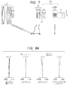
- FIG. 5 is a lens sectional diagram of a zoom lens according to Numerical Embodiment 3 at the wide angle end, focused at infinity.
- FIG. 6A is an aberration diagram of the zoom lens according to Numerical Embodiment 3 at the wide angle end, focused at infinity.
- FIG. 6D is an aberration diagram of the zoom lens according to Numerical Embodiment 3 at the telephoto end, focused at infinity.
- FIG. 7 is a lens sectional diagram of a zoom lens according to Numerical Embodiment 4 at the wide angle end, focused at infinity.
- FIG. 8A is an aberration diagram of the zoom lens according to Numerical Embodiment 4 at the wide angle end, focused at infinity.
- FIG. 8E is an aberration diagram of the zoom lens according to Numerical Embodiment 4 at the telephoto end, focused at infinity.
- FIG. 9 is a lens sectional diagram of a zoom lens according to Numerical Embodiment 5 at the wide angle end, focused at infinity.
- FIG. 10A is an aberration diagram of the zoom lens according to Numerical Embodiment 5 at the wide angle end, focused at infinity.
- FIG. 10D is an aberration diagram of the zoom lens according to Numerical Embodiment 5 at the telephoto end, focused at infinity.
- FIG. 11 is a lens sectional diagram of a zoom lens according to Numerical Embodiment 6 at the wide angle end, focused at infinity.
- FIG. 12A is an aberration diagram of the zoom lens according to Numerical Embodiment 6 at the wide angle end, focused at infinity.
- FIG. 12D is an aberration diagram of the zoom lens according to Numerical Embodiment 6 at the telephoto end, focused at infinity.
- FIG. 13A is a diagram illustrating an optical path in the zoom lens of Numerical Embodiment 1 at the wide angle end.
- FIG. 13C is a diagram illustrating an optical path in the zoom lens of Numerical Embodiment 1 at the telephoto end.
- FIG. 14 is a schematic diagram illustrating a main portion of an image pickup apparatus of the present invention.
- a zoom lens of the present invention is described based on conditional expressions.
- the movement loci of a second lens unit and a third lens unit of the zoom lens of the present invention are defined so that the zoom lens can achieve a wide angle of view, a high zoom ratio, size and weight reduction, and high optical performance over the entire zoom range.
- the zoom lens of the present invention and an image pickup apparatus having the same includes, in order from an object side to an image side, a first lens unit having a positive refractive power, a second lens unit having a negative refractive power, a third lens unit having a negative refractive power, an intermediate lens group including at least one lens unit, and a rear lens group including at least one lens unit.
- An aperture stop is placed either on the object side of the rear lens group or inside the rear lens group.
- the first lens unit is configured not to move for zooming
- the second lens unit is configured to move for zooming
- the third lens unit is configured to move for zooming
- the intermediate lens group is configured to move for zooming.
- the lens unit in the rear lens group closest to the object side is configured not to move for zooming.
- the rear lens group is configured not to move for zooming if the rear lens group includes only one lens unit, and that the lens unit in the rear lens group closest to the object is configured not to move for zooming if the rear lens group includes more than one lens unit. Further, the zoom lens is so configured that the distances between the adjacent lens units change for zooming.
- “L1” to “L5” denote the first to fifth lens units, respectively.
- the movement loci of the second lens and the third lens are set so that the distance between the second lens unit and the third lens unit may be widened for zooming from the wide angle end to the zoom middle range (fw ⁇ Z 0.7 to fw ⁇ Z 0.9 ), and become a predetermined distance for zooming from the zoom middle range to the telephoto end. Optical effects by this are described.
- the beam height of the principal ray of off-axial rays passing through the first lens unit start to descend particularly in the zoom middle range (fw ⁇ Z 0.7 to fw ⁇ Z 0.9 ), and therefore the curvature of field tends to occur in an overcorrected direction (to the image side).
- the beam height of the off-axial rays passing through the third lens unit is lowered, which reduces the curvature of field in the overcorrected direction occurring in the third lens unit.
- the curvature of field in the overcorrected direction which tends to occur in the zoom middle range can be favorably corrected.
- Expressions (1) and (2) define the distances between the second lens unit and the third lens unit in the zoom middle range (fw ⁇ Z 0.7 to fw ⁇ Z 0.9 ).
- the zoom lens can favorably correct curvature of field in the zoom middle range, achieving high optical performance over the entire zoom range.
- the zoom lens does not satisfy the upper limit of Expression (1), the distance between the third lens unit and the third lens unit becomes so long that it is difficult to correct axial chromatic aberration in the zoom middle range.
- the zoom lens does not satisfy the lower limit of Expression (1), the distance between the second lens unit and the third lens unit is not long enough relative to that at the wide angle end, and the above-described effects of the curvature of field correction becomes so small that it is difficult to achieve high optical performance over the entire zoom range.
- the zoom lens achieves both size reduction and high optical performance.
- the distance between the second lens unit and the third lens unit becomes so long that it is difficult to correct axial chromatic aberration in the zoom middle range.
- the zoom lens does not satisfy the lower limit of Expression (2) the distance between the second lens unit and the third lens unit at the telephoto end becomes too long relative to that in the zoom middle range. Consequently, the combined focal length of the second lens unit and the third lens unit becomes short, and zooming roles assigned to the second lens unit and the third lens unit become small.
- the zoom ratio is reduced as a result, making it difficult to reduce the size of the zoom lens. It is preferable when numerical values in Expressions (1) and (2) are set as follows: 1.32 ⁇ L 2max/ L 2 w ⁇ 2.20, and (1a) 0.9 ⁇ L 2max/ L 2 t ⁇ 3.0. (2a)
- the rear lens group has at least two convex lenses and at least one concave lens, and is configured not to move for zooming.
- the rear lens group has at least two convex lenses and at least one concave lens.
- a lens unit LRR which is one of the lens units in the rear lens group, is configured to move for zooming.
- the zoom lens satisfies the following expression:
- the lens unit LRR may move for zooming within the range satisfying Expression (3) to correct off-axial aberration. Further, defocusing caused by zooming may be corrected by moving the lens unit LRR in conjunction with a zooming operation.
- the zoom lens satisfies the following expression: ⁇ 10.0 ⁇ f 1 ⁇ ( f 2+ f 3)/( f 2 ⁇ f 3) ⁇ 2.0 (4)
- f1, f2, and f3 are the focal lengths of the first lens unit, the second lens unit, and the third lens unit, respectively.
- a numerical value of (f2 ⁇ f3)/(f2+f3) corresponds to the combined focal length of the second lens unit and the third lens unit.
- the zoom lens does not satisfy the upper limit of Expression (4), the first lens unit has too strong a refractive power relative to the second lens unit, which makes it difficult to correct distortion at the wide angle end or axial chromatic aberration at the telephoto end.
- the zoom lens does not satisfy the lower limit of Expression (4), the first lens unit has too weak a refractive power relative to the second lens unit, which increases the size of the first lens unit in particular, making size reduction difficult. It is preferable when the numerical values in Expression (4) are set as follows: —8.5 ⁇ f 1 ⁇ ( f 2+ f 3)/( f 2 ⁇ f 3) ⁇ 3.5 (4a)
- the zoom lens satisfies the following expression: 0.1 ⁇ f 2/ f 3 ⁇ 10.0 (5) where f2 and f3 are the focal lengths of the second lens unit and the third lens unit, respectively.
- the zoom lens does not satisfy the upper limit of Expression (5), the third lens unit has too strong a refractive power relative to the second lens unit, and the third lens unit becomes more sensitive to manufacturing error at the telephoto end. In particular, the curvature of field and comatic aberration occur more, degrading manufacturability.
- the zoom lens does not satisfy the lower limit of Expression (5), the second lens unit has too strong a refractive power relative to the third lens unit, which increases aberrations occurring in the second lens unit, making it difficult to achieve high optical performance over the entire zoom range. It is preferable when the numerical values in Expression (5) are set as follows: 0.15 ⁇ f 2/ f 3 ⁇ 6.00. (5a)
- the second lens unit and the third lens unit collectively include at least one convex lens and at least two concave lenses.
- Such a lens configuration enables the lenses constituting the second lens unit and the third lens unit to have appropriate refractive powers to be able to favorably correct the aberrations in the zoom middle range and axial chromatic aberration at the telephoto end.
- the second lens unit or the third lens unit has at least one aspherical surface. This achieves effective correction of the curvature of field and spherical aberration in the zoom middle range.
- the zoom lens satisfies the following expression: ⁇ 2 ⁇ ( R 2+ R 3)/( R 2 ⁇ R 3) ⁇ 30 (6)
- R2 is the radius of curvature of the surface of the second lens unit closest to the image side
- R3 is the radius of curvature of the surface of the third lens unit closest to the object side.
- the image pickup apparatus of the present invention is characterized by including the zoom lens of any of the embodiments and a solid-state image pickup element having a predetermined effective image pickup range for receiving an optical image formed by the zoom lens.
- the specific configuration of the zoom lens of the present invention is described based on the characteristics of the lens configurations of Numerical Embodiments 1 to 6 corresponding to Embodiments 1 to 6.
- FIG. 1 is a lens sectional diagram of a zoom lens of Embodiment 1 (Numerical Embodiment 1) of the present invention at the wide angle end, focused at infinity.
- FIGS. 2A, 2B, 2C, and 2D are longitudinal aberration diagrams of the zoom lens of Numerical Embodiment 1 at the wide angle end, the focal length of 145.5 mm (fw ⁇ Z 0.7 ), the focal length of 304.3 mm (fw ⁇ Z 0.9 ), and the telephoto end, respectively.
- the zoom lens is focused at infinity in all the longitudinal aberration diagrams.
- the values of the focal lengths are ones in the numerical embodiments given later expressed in millimeters. This also applies to the rest of the numerical embodiments.
- the focal length of 145.5 mm is a zoom position where the distance between the second lens unit and the third lens unit is at the maximum in the range from fw ⁇ Z 0.7 to fw ⁇ Z 0.9 .
- the zoom lens in FIG. 1 includes, in order from the object side, a first lens unit L1 for focusing which has a positive refractive power, a second lens unit L2 for zooming and a third lens unit L3 which have negative refractive powers and move to the image side for zooming from the wide angle end to the telephoto end, a fourth lens unit L4 which has a negative refractive power and moves on the optical axis nonlinearly in conjunction with the movements of the second lens unit L2 and the third lens unit L3 to correct image plane displacement caused by the zooming, and a fifth lens unit L5 which is configured not to move for zooming and performs imaging effect.
- the fourth lens unit L4 forms the intermediate lens group.
- the second lens unit L2, the third lens unit L3, and the fourth lens unit L4 constitute a zooming system.
- SP denotes an aperture stop and is placed between the fourth lens unit L4 and the fifth lens unit L5. The aperture stop does not move in the optical axis direction for zooming.
- P denotes a glass block corresponding to an optical filter or a color separation optical system placed inside the image pickup apparatus to which the zoom lens of the present invention is connected.
- I is an image plane.
- the image plane I is the image pickup surface of, for example, a solid-state image pickup element (photoelectric conversion element) that receives an optical image formed by the zoom lens and converts it photo-electrically.
- the image plane I is a film plane that is sensitive to an optical image formed by the zoom lens.
- the solid line and the two-dot dash line in the part showing spherical aberration denote e-line and g-line, respectively.
- the broken line and the solid line denote the meridional image plane and the sagittal image plane, respectively.
- the two-dot dash line denotes g-line.
- ⁇ denotes a half angle of view
- Fno denotes an f-number.
- the spherical aberration is expressed based on a scale ranging from ⁇ 0.4 to 0.4 mm, the astigmatism based on a scale ranging from ⁇ 0.4 to 0.4 mm, the distortion based on a scale ranging from ⁇ 10% to 10%, and the lateral chromatic aberration based on a scale ranging from ⁇ 0.05 mm to 0.05 mm.
- the wide angle end and the telephoto end refer to zoom positions which are available ends of the zoom range in which the second lens unit L2 for zooming can move on an optical axis mechanically.
- the first lens unit L1 corresponds to the first to tenth surfaces
- the second lens unit L2 the 11th to 16th surfaces
- the third lens unit L3 the 17th to 18th surfaces
- the fourth lens unit L4 the 19th to 21st surfaces
- the fifth lens unit L5 the 23rd to 42nd surfaces.
- the second lens unit L2 includes a total of three lenses including convex and concave lenses
- the third lens unit L3 includes one concave lens.
- Numerical Embodiment 1 corresponding to Embodiment 1.
- “i” represents the ordinal number of a surface (an optical surface) from the object side
- “ri” represents the radius of curvature of the i-th surface from the object side
- “di” represents the distance (on the optical axis) between the i-th surface and the (i+1)-th surface from the object side.
- “ndi” and “vdi” respectively represent the refractive index and the Abbe number of a medium (an optical member) between the i-th surface and the (i+1)-th surface
- “BF” represents a back focal length in air.
- An aspherical shape is expressed as follows when an X axis is the optical-axis direction, an H axis is perpendicular to the optical axis, and a light travelling direction is positive:
- X H 2 / R 1 + 1 - ( 1 + k ) ⁇ ( H / R ) 2 + A ⁇ ⁇ 4 ⁇ H 4 + A ⁇ ⁇ 6 ⁇ H 6 + A ⁇ ⁇ 8 ⁇ H 8 + A ⁇ ⁇ 10 ⁇ H 10 + A ⁇ ⁇ 12 ⁇ H 12 + A ⁇ ⁇ 14 ⁇ H 14 + A ⁇ ⁇ 16 ⁇ H 16
- R is a paraxial curvature radius
- k is a conic constant
- A4, A6, A8, A10, A12, A14, and A16 are each an aspherical coefficient.
- “e-Z” indicates “X10 ⁇ Z”.
- Table 1 shows numerical values in the conditional expressions for the present embodiment.
- the present embodiment satisfies Expressions (1), (2), (4) to (6). Since the movement loci of the second lens unit and the third lens unit are appropriately set, the zoom lens of the present embodiment favorably corrects the aberrations over the entire zoom range, achieving both high optical performance and reduction in size and weight.
- the zoom lens of the present invention must satisfy Expressions (1) and (2), but does not have to satisfy Expressions (3) to (6). Nonetheless, better effects are produced when at least one of Expressions (3) to (6) is satisfied. This is true for the rest of the embodiments.
- FIG. 14 is a schematic diagram of an image pickup apparatus (a television camera system) using the zoom lens of any of the embodiments as its image pickup optical system.
- reference numeral “ 101 ” denotes the zoom lens of any of Embodiments 1 to 6, and “ 124 ” denotes a camera.
- the zoom lens 101 is attachable to and detachable from the camera 124 .
- Reference numeral “ 125 ” denotes an image pickup apparatus formed by attaching the zoom lens 101 to the camera 124 .
- the zoom lens 101 has a first lens unit F, a zooming part LZ, and a rear lens group R for forming an image.
- the first lens unit F includes a lens unit for focusing.
- the zooming part LZ includes a second lens unit and a third lens unit that move on the optical axis for zooming and a fourth lens unit that moves on the optical axis for correcting image plane displacement caused by zooming.
- SP denotes an aperture stop.
- Reference numerals “ 114 ” and “ 115 ” denote driving mechanisms, such as a helicoid or a cam, that drive the first lens unit F and the zooming part LZ, respectively, in the optical-axis direction.
- Reference numerals “ 116 ” to “ 118 ” are motors (driving means) that electrically drive the driving mechanism 114 , the driving mechanism 115 , and the aperture stop SP, respectively.
- Reference numerals “ 119 ” to “ 121 ” are detectors, such as encoders, potentiometers, or photo-sensors, that detect the position of the first lens unit F on the optical axis, the position of the zooming part LZ on the optical axis, and the aperture diameter of the aperture stop SP, respectively.
- “ 109 ” denotes a glass block corresponding to an optical filter or a color separation optical system in the camera 124
- “ 110 ” denotes a solid-state image pickup element (photoelectric conversion element), such as a CCD or CMOS sensor, that receives a subject's optical image formed by the zoom lens 101 .
- “ 111 ” and “ 122 ” are CPUs that control driving of the camera 124 and the zoom lens 101 , respectively.
- the zoom lens of the present invention When the zoom lens of the present invention is thus applied to an image pickup apparatus, or in the above example a television camera, the image pickup apparatus can achieve high optical performance.
- FIG. 3 is a lens sectional diagram of a zoom lens of Embodiment 2 (Numerical Embodiment 2) of the present invention at the wide angle end, focused at infinity.
- FIGS. 4A, 4B, 4C, and 4D are longitudinal aberration diagrams of the zoom lens of Numerical Embodiment 2 at the wide angle end, the focal length of 145.5 mm (fw ⁇ Z 0.7 ), the focal length of 304.3 mm (fw ⁇ Z 0.9 ), and the telephoto end, respectively.
- the zoom lens is focused at infinity in all the longitudinal aberration diagrams.
- the focal length of 304.3 mm is a zoom position where the distance between the second lens unit and the third lens unit is at the maximum in the range from fw ⁇ Z 0.7 to fw ⁇ Z 0.9 .
- the zoom lens in FIG. 3 includes, in order from the object side, a first lens unit L1 for focusing which has a positive refractive power, a second lens unit L2 for zooming and a third lens unit L3 which have negative refractive powers and move to the image side for zooming from the wide angle end to the telephoto end, a fourth lens unit L4 which has a negative refractive power and moves on the optical axis nonlinearly in conjunction with the movements of the second lens unit L2 and the third lens unit L3 to correct image plane displacement caused by the zooming, and a fifth lens unit L5 which is configured not to move for zooming and performs imaging effect.
- the fourth lens unit L4 forms the intermediate lens group.
- the lens configurations of the lens units are the same as those in Numerical Embodiment 1.
- Table 1 shows numerical values in the conditional expressions for the present embodiment.
- the present embodiment satisfies Expressions (1), (2), (4) to (6). Since the movement loci of the second lens unit and the third lens unit are appropriately set, the zoom lens of the present embodiment favorably corrects the aberrations over the entire zoom range, achieving both high optical performance and reduction in size and weight.
- FIG. 5 is a lens sectional diagram of a zoom lens of Embodiment 3 (Numerical Embodiment 3) of the present invention at the wide angle end, focused at infinity.
- FIGS. 6A, 6B, 6C, and 6D are longitudinal aberration diagrams of the zoom lens of Numerical Embodiment 3 at the wide angle end, the focal length of 145.5 mm (fw ⁇ Z 0.7 ), the focal length of 304.3 mm (fw ⁇ Z 0.9 ), and the telephoto end, respectively.
- the zoom lens is focused at infinity in all the longitudinal aberration diagrams.
- the focal length of 145.5 mm is a zoom position where the distance between the second lens unit and the third lens unit is at the maximum in the range from fw ⁇ Z 0.7 to fw ⁇ Z 0.9 .
- the zoom lens in FIG. 5 includes, in order from the object side, a first lens unit L1 for focusing which has a positive refractive power, a second lens unit L2 for zooming and a third lens unit L3 which have negative refractive powers and move to the image side for zooming from the wide angle end to the telephoto end, a fourth lens unit L4 and a fifth lens unit L5 which have a negative refractive power and a positive refractive power, respectively, and move on the optical axis nonlinearly in conjunction with the movements of the second lens unit L2 and the third lens unit L3, and a sixth lens unit L6 which is configured not to move for zooming and performs imaging effect.
- the fourth lens unit L4 and the fifth lens unit L5 form the intermediate lens group.
- the first lens unit L1 corresponds to the first to tenth surfaces
- the second lens unit L2 the 11th to 16th surfaces
- the third lens unit L3 the 17th to 18th surfaces
- the fourth lens unit L4 the 19th to 21st surfaces
- the fifth lens unit L5 the 22nd to 25th surfaces
- the sixth lens unit L6 the 27th to 42nd surfaces.
- the second lens unit L2 includes a total of three convex and concave lenses
- the third lens unit L3 includes one concave lens.
- Table 1 shows numerical values in the conditional expressions for the present embodiment.
- the present embodiment satisfies Expressions (1), (2), (4) to (6). Since the movement loci of the second lens unit and the third lens unit are appropriately set, the zoom lens of the present embodiment favorably corrects the aberrations over the entire zoom range, achieving both high optical performance and reduction in size and weight.
- FIG. 7 is a lens sectional diagram of a zoom lens of Embodiment 4 (Numerical Embodiment 4) of the present invention at the wide angle end, focused at infinity.
- FIGS. 8A, 8B, 8C, 8D, and 8E are longitudinal aberration diagrams of the zoom lens of Numerical Embodiment 4 at the wide angle end, the focal length of 145.5 mm (fw ⁇ Z 0.7 ), the focal length of 200.5 mm (a zoom position where the distance between the second lens unit and the third lens unit is at the maximum in the range from fw ⁇ Z 0.7 to fw ⁇ Z 0.9 ), the focal length of 304.3 mm (fw ⁇ Z 0.9 ), and the telephoto end, respectively.
- the zoom lens is focused at infinity in all the longitudinal aberration diagrams.
- the focal length of 200.5 mm is a zoom position where the distance between the second lens unit and the third lens unit is at the maximum in the range from fw ⁇ Z 0.7 to fw ⁇ Z 0.9 .
- the zoom lens in FIG. 7 includes, in order from the object side, a first lens unit L1 for focusing which has a positive refractive power, a second lens unit L2 for zooming and a third lens unit L3 which have negative refractive powers and move to the image side for zooming from the wide angle end to the telephoto end, a fourth lens unit L4 and a fifth lens unit L5 which have a negative refractive power and a positive refractive power, respectively, and move on the optical axis nonlinearly in conjunction with the movements of the second lens unit L2 and the third lens unit L3, a sixth lens unit L6 which is configured not to move for zooming, and a seventh lens unit L7 which is configured to move for zooming.
- the fourth lens unit L4 and the fifth lens unit L5 form the intermediate lens group
- the sixth lens unit L6 and the seventh lens unit L7 form the rear lens group
- the seventh lens unit L7 corresponds to the lens unit LRR which is part of the rear lens group.
- the first lens unit L1 corresponds to the first to tenth surfaces
- the second lens unit L2 the 11th to 12th surfaces
- the third lens unit L3 the 13th to 18th surfaces
- the fourth lens unit L4 the 19th to 21st surfaces
- the fifth lens unit L5 the 22nd to 25th surfaces
- the sixth lens unit L6 the 27th to 32nd surfaces
- the seventh lens unit L7 the 33rd to 42nd surfaces.
- the second lens unit L2 includes one concave lens
- the third lens unit L3 includes a total of three convex and concave lenses.
- Table 1 shows numerical values in the conditional expressions for the present embodiment.
- the present embodiment satisfies Expressions (1) to (6). Since the movement loci of the second lens unit and the third lens unit are appropriately set, the zoom lens of the present embodiment favorably corrects the aberrations over the entire zoom range, achieving both high optical performance and reduction in size and weight.
- FIG. 9 is a lens sectional diagram of a zoom lens of Embodiment 5 (Numerical Embodiment 5) of the present invention at the wide angle end, focused at infinity.
- FIGS. 10A, 10B, 10C, and 10D are longitudinal aberration diagrams of the zoom lens of Numerical Embodiment 5 at the wide angle end, the focal length of 58.1 mm (fw ⁇ Z 0.7 ), the focal length of 102.44 mm (fw ⁇ Z 0.9 ), and the telephoto end, respectively.
- the zoom lens is focused at infinity in all the longitudinal aberration diagrams.
- the focal length of 102.44 mm is a zoom position where the distance between the second lens unit and the third lens unit is at the maximum in the range from fw ⁇ Z 0.7 to fw ⁇ Z 0.9 .
- the zoom lens in FIG. 9 includes, in order from the object side, a first lens unit L1 for focusing which has a positive refractive power, a second lens unit L2 for zooming and a third lens unit L3 which have negative refractive powers and move to the image side for zooming from the wide angle end to the telephoto end, a fourth lens unit L4 and a fifth lens unit L5 which have a negative refractive power and a positive refractive power, respectively, and move on the optical axis nonlinearly in conjunction with the movements of the second lens unit L2 and the third lens unit L3, and a sixth lens unit L6 which is configured not to move for zooming and performs imaging effect.
- the fourth lens unit L4 and the fifth lens unit L5 form the intermediate lens group.
- the first lens unit L1 corresponds to the first to tenth surfaces
- the second lens unit L2 the 11th to 17th surfaces
- the third lens unit L3 the 18th to 19th surfaces
- the fourth lens unit L4 the 20th to 22nd surfaces
- the fifth lens unit L5 the 23rd to 26th surfaces
- the sixth lens unit L6 the 28th to 40th surfaces.
- the second lens unit L2 includes a total of four convex and concave lenses
- the third lens unit L3 includes one concave lens.
- Table 1 shows numerical values in the conditional expressions for the present embodiment.
- the present embodiment satisfies Expressions (1), (2), (4) to (6). Since the movement loci of the second lens unit and the third lens unit are appropriately set, the zoom lens of the present embodiment favorably corrects the aberrations over the entire zoom range, achieving both high optical performance and reduction in size and weight.
- FIG. 11 is a lens sectional diagram of a zoom lens of Embodiment 6 (Numerical Embodiment 6) of the present invention at the wide angle end, focused at infinity.
- FIGS. 12A, 12B, 12C, and 12D are longitudinal aberration diagrams of the zoom lens of Numerical Embodiment 6 at the wide angle end, the focal length of 233.61 mm (fw ⁇ Z 0.7 ), the focal length of 586.8 mm (fw ⁇ Z 0.9 ), and the telephoto end, respectively.
- the zoom lens is focused at infinity in all the longitudinal aberration diagrams.
- the focal length of 233.61 mm is a zoom position where the distance between the second lens unit and the third lens unit is at the maximum in the range from fw ⁇ Z 0.7 to fw ⁇ Z 0.9 .
- the zoom lens in FIG. 11 includes, in order from the object side, a first lens unit L1 for focusing which has a positive refractive power, a second lens unit L2 for zooming and a third lens unit L3 which have negative refractive powers and move to the image side for zooming from the wide angle end to the telephoto end, a fourth lens unit L4 and a fifth lens unit L5 which have positive refractive powers and move on the optical axis nonlinearly in conjunction with the movements of the second lens unit L2 and the third lens unit L3, and a sixth lens unit L6 which is configured not to move for zooming and performs imaging effect.
- the fourth lens unit L4 and the fifth lens unit L5 form the intermediate lens group.
- the first lens unit L1 corresponds to the first to tenth surfaces
- the second lens unit L2 the 11th to 15th surfaces
- the third lens unit L3 the 16th to 18th surfaces
- the fourth lens unit L4 the 19th to 25th surfaces
- the fifth lens unit L5 the 26th to 27th surfaces
- the sixth lens unit L6 the 29th to 49th surfaces.
- the second lens unit L2 includes a total of three convex and concave lenses
- the third lens unit L3 includes a total of two convex and concave lenses.
- Table 1 shows numerical values in the conditional expressions for the present embodiment.
- the present embodiment satisfies Expressions (1), (2), (4) to (6). Since the movement loci of the second lens unit and the third lens unit are appropriately set, the zoom lens of the present embodiment favorably corrects the aberrations over the entire zoom range, achieving both high optical performance and reduction in size and weight.
Landscapes
- Physics & Mathematics (AREA)
- General Physics & Mathematics (AREA)
- Optics & Photonics (AREA)
- Nonlinear Science (AREA)
- Lenses (AREA)
Applications Claiming Priority (2)
| Application Number | Priority Date | Filing Date | Title |
|---|---|---|---|
| JP2017-021499 | 2017-02-08 | ||
| JP2017021499A JP6862203B2 (ja) | 2017-02-08 | 2017-02-08 | ズームレンズ及びそれを有する撮像装置 |
Publications (2)
| Publication Number | Publication Date |
|---|---|
| US20180224640A1 US20180224640A1 (en) | 2018-08-09 |
| US10670845B2 true US10670845B2 (en) | 2020-06-02 |
Family
ID=61131888
Family Applications (1)
| Application Number | Title | Priority Date | Filing Date |
|---|---|---|---|
| US15/889,520 Active 2038-07-05 US10670845B2 (en) | 2017-02-08 | 2018-02-06 | Zoom lens and image pickup apparatus having the same |
Country Status (4)
| Country | Link |
|---|---|
| US (1) | US10670845B2 (enExample) |
| EP (1) | EP3361301B1 (enExample) |
| JP (1) | JP6862203B2 (enExample) |
| CN (1) | CN108398773B (enExample) |
Cited By (3)
| Publication number | Priority date | Publication date | Assignee | Title |
|---|---|---|---|---|
| US11435564B2 (en) | 2019-08-16 | 2022-09-06 | Canon Kabushiki Kaisha | Zoom lens and image pickup apparatus |
| US11789249B2 (en) | 2021-02-12 | 2023-10-17 | Canon Kabushiki Kaisha | Zoom lens and image pickup apparatus |
| US11921268B2 (en) | 2021-02-12 | 2024-03-05 | Canon Kabushiki Kaisha | Zoom lens and image pickup apparatus |
Families Citing this family (7)
| Publication number | Priority date | Publication date | Assignee | Title |
|---|---|---|---|---|
| JP7039241B6 (ja) * | 2017-10-12 | 2022-04-18 | キヤノン株式会社 | ズームレンズ及び撮像装置 |
| JP7129178B2 (ja) | 2018-02-28 | 2022-09-01 | キヤノン株式会社 | ズームレンズ及び撮像装置 |
| JP7207854B2 (ja) | 2018-02-28 | 2023-01-18 | キヤノン株式会社 | ズームレンズ及び撮像装置 |
| JP6772209B2 (ja) | 2018-02-28 | 2020-10-21 | キヤノン株式会社 | ズームレンズ及び撮像装置 |
| CN109164563B (zh) * | 2018-09-17 | 2020-08-18 | 河北汉光重工有限责任公司 | 一种超大像面大相对孔径高清连续变焦光学系统 |
| JP2020085934A (ja) * | 2018-11-15 | 2020-06-04 | キヤノン株式会社 | ズームレンズ及び撮像装置 |
| JP7286341B2 (ja) * | 2019-02-22 | 2023-06-05 | キヤノン株式会社 | ズームレンズおよび撮像装置 |
Citations (17)
| Publication number | Priority date | Publication date | Assignee | Title |
|---|---|---|---|---|
| US20120262798A1 (en) | 2011-04-15 | 2012-10-18 | Canon Kabushiki Kaisha | Zoom lens and image pickup apparatus including the same |
| US20120262608A1 (en) | 2011-04-15 | 2012-10-18 | Canon Kabushiki Kaisha | Zoom lens and image pickup apparatus including the same |
| WO2013031203A1 (ja) | 2011-08-30 | 2013-03-07 | 富士フイルム株式会社 | 変倍光学系および撮像装置 |
| US20140049672A1 (en) * | 2012-08-17 | 2014-02-20 | Canon Kabushiki Kaisha | Zoom lens and image pickup apparatus including the same |
| JP2015161693A (ja) | 2014-02-26 | 2015-09-07 | 富士フイルム株式会社 | ズームレンズおよび撮像装置 |
| JP2016024341A (ja) | 2014-07-22 | 2016-02-08 | キヤノン株式会社 | ズームレンズ及びそれを有する撮像装置 |
| US9264638B2 (en) | 2013-11-12 | 2016-02-16 | Canon Kabushiki Kaisha | Zoom lens and image pickup apparatus including the same |
| US9268120B2 (en) | 2013-11-12 | 2016-02-23 | Canon Kabushiki Kaisha | Zoom lens and image pickup apparatus including the same |
| US9310592B2 (en) | 2013-11-12 | 2016-04-12 | Canon Kabushiki Kaisha | Zoom lens and image pickup apparatus including the same |
| US9329372B2 (en) | 2013-08-08 | 2016-05-03 | Canon Kabushiki Kaisha | Zoom lens and image pickup apparatus having the same |
| US9400374B2 (en) | 2013-01-23 | 2016-07-26 | Canon Kabushiki Kaisha | Zoom lens and image pickup apparatus including the same |
| JP2016173529A (ja) | 2015-03-18 | 2016-09-29 | キヤノン株式会社 | ズームレンズ及びそれを有する撮像装置 |
| JP2016173530A (ja) | 2015-03-18 | 2016-09-29 | キヤノン株式会社 | ズームレンズ及びそれを有する撮像装置 |
| US20170108678A1 (en) | 2015-10-20 | 2017-04-20 | Canon Kabushiki Kaisha | Zoom lens and image pickup apparatus including the same |
| US9678318B2 (en) | 2013-11-12 | 2017-06-13 | Canon Kabushiki Kaisha | Zoom lens and image pickup apparatus including the same |
| US9716829B2 (en) | 2014-12-09 | 2017-07-25 | Canon Kabushiki Kaisha | Zoom lenses and image pickup apparatus including the zoom lenses |
| US9904043B2 (en) | 2015-10-20 | 2018-02-27 | Canon Kabushiki Kaisha | Zoom lens and image pickup apparatus including the same |
Family Cites Families (5)
| Publication number | Priority date | Publication date | Assignee | Title |
|---|---|---|---|---|
| JPH03293613A (ja) * | 1990-04-12 | 1991-12-25 | Konica Corp | ズームレンズ |
| JP5009758B2 (ja) * | 2007-11-26 | 2012-08-22 | 富士フイルム株式会社 | 投影用ズームレンズおよび投写型表示装置 |
| JP2013003384A (ja) * | 2011-06-17 | 2013-01-07 | Konica Minolta Advanced Layers Inc | 大口径変倍光学系および撮像装置 |
| JP5841270B2 (ja) * | 2013-01-22 | 2016-01-13 | 富士フイルム株式会社 | ズームレンズおよび撮像装置 |
| KR102001220B1 (ko) * | 2013-03-12 | 2019-07-17 | 삼성전자주식회사 | 망원 줌 렌즈계 및 이를 포함한 촬영 장치 |
-
2017
- 2017-02-08 JP JP2017021499A patent/JP6862203B2/ja active Active
-
2018
- 2018-01-31 EP EP18000080.4A patent/EP3361301B1/en active Active
- 2018-02-05 CN CN201810109508.3A patent/CN108398773B/zh active Active
- 2018-02-06 US US15/889,520 patent/US10670845B2/en active Active
Patent Citations (17)
| Publication number | Priority date | Publication date | Assignee | Title |
|---|---|---|---|---|
| US20120262608A1 (en) | 2011-04-15 | 2012-10-18 | Canon Kabushiki Kaisha | Zoom lens and image pickup apparatus including the same |
| US20120262798A1 (en) | 2011-04-15 | 2012-10-18 | Canon Kabushiki Kaisha | Zoom lens and image pickup apparatus including the same |
| WO2013031203A1 (ja) | 2011-08-30 | 2013-03-07 | 富士フイルム株式会社 | 変倍光学系および撮像装置 |
| US20140049672A1 (en) * | 2012-08-17 | 2014-02-20 | Canon Kabushiki Kaisha | Zoom lens and image pickup apparatus including the same |
| US9400374B2 (en) | 2013-01-23 | 2016-07-26 | Canon Kabushiki Kaisha | Zoom lens and image pickup apparatus including the same |
| US9329372B2 (en) | 2013-08-08 | 2016-05-03 | Canon Kabushiki Kaisha | Zoom lens and image pickup apparatus having the same |
| US9678318B2 (en) | 2013-11-12 | 2017-06-13 | Canon Kabushiki Kaisha | Zoom lens and image pickup apparatus including the same |
| US9264638B2 (en) | 2013-11-12 | 2016-02-16 | Canon Kabushiki Kaisha | Zoom lens and image pickup apparatus including the same |
| US9268120B2 (en) | 2013-11-12 | 2016-02-23 | Canon Kabushiki Kaisha | Zoom lens and image pickup apparatus including the same |
| US9310592B2 (en) | 2013-11-12 | 2016-04-12 | Canon Kabushiki Kaisha | Zoom lens and image pickup apparatus including the same |
| JP2015161693A (ja) | 2014-02-26 | 2015-09-07 | 富士フイルム株式会社 | ズームレンズおよび撮像装置 |
| JP2016024341A (ja) | 2014-07-22 | 2016-02-08 | キヤノン株式会社 | ズームレンズ及びそれを有する撮像装置 |
| US9716829B2 (en) | 2014-12-09 | 2017-07-25 | Canon Kabushiki Kaisha | Zoom lenses and image pickup apparatus including the zoom lenses |
| JP2016173529A (ja) | 2015-03-18 | 2016-09-29 | キヤノン株式会社 | ズームレンズ及びそれを有する撮像装置 |
| JP2016173530A (ja) | 2015-03-18 | 2016-09-29 | キヤノン株式会社 | ズームレンズ及びそれを有する撮像装置 |
| US20170108678A1 (en) | 2015-10-20 | 2017-04-20 | Canon Kabushiki Kaisha | Zoom lens and image pickup apparatus including the same |
| US9904043B2 (en) | 2015-10-20 | 2018-02-27 | Canon Kabushiki Kaisha | Zoom lens and image pickup apparatus including the same |
Non-Patent Citations (2)
| Title |
|---|
| European Search Report dated Jul. 19, 2018 corresponding to European Appln. No. EP 18 00 0080.4 (9 pages). |
| Extended European Search Report dated Jun. 20, 2018 corresponding to European Appln. No. EP 18 00 0080, 9 pages. |
Cited By (3)
| Publication number | Priority date | Publication date | Assignee | Title |
|---|---|---|---|---|
| US11435564B2 (en) | 2019-08-16 | 2022-09-06 | Canon Kabushiki Kaisha | Zoom lens and image pickup apparatus |
| US11789249B2 (en) | 2021-02-12 | 2023-10-17 | Canon Kabushiki Kaisha | Zoom lens and image pickup apparatus |
| US11921268B2 (en) | 2021-02-12 | 2024-03-05 | Canon Kabushiki Kaisha | Zoom lens and image pickup apparatus |
Also Published As
| Publication number | Publication date |
|---|---|
| JP2018128572A (ja) | 2018-08-16 |
| JP6862203B2 (ja) | 2021-04-21 |
| EP3361301A1 (en) | 2018-08-15 |
| CN108398773B (zh) | 2021-04-09 |
| EP3361301B1 (en) | 2023-09-20 |
| CN108398773A (zh) | 2018-08-14 |
| US20180224640A1 (en) | 2018-08-09 |
| EP3361301A3 (en) | 2018-11-21 |
Similar Documents
| Publication | Publication Date | Title |
|---|---|---|
| US10670845B2 (en) | Zoom lens and image pickup apparatus having the same | |
| US9268120B2 (en) | Zoom lens and image pickup apparatus including the same | |
| US10222594B2 (en) | Zoom lens and image pickup apparatus including the same | |
| US8879164B2 (en) | Zoom lens and image pickup apparatus having the same | |
| US9684155B2 (en) | Optical system and image pickup apparatus including the same | |
| US9329372B2 (en) | Zoom lens and image pickup apparatus having the same | |
| US11137586B2 (en) | Zoom lens and image pickup apparatus | |
| US8736971B2 (en) | Zoom lens and image pickup apparatus including the same | |
| US8743469B2 (en) | Zoom lens and image pickup apparatus including the same | |
| US10670834B2 (en) | Zoom lens and image pickup apparatus | |
| JP5751991B2 (ja) | ズームレンズ及びそれを有する撮像装置 | |
| US10295803B2 (en) | Zoom lens and image pickup apparatus having the same | |
| US10908401B2 (en) | Zoom lens and image pickup apparatus | |
| US11137583B2 (en) | Zoom lens and image capturing apparatus | |
| US10571670B2 (en) | Zoom lens and image pickup apparatus including the same | |
| EP4636453A2 (en) | Zoom lens | |
| JP2013050519A5 (enExample) | ||
| US12292556B2 (en) | Zoom lens and image pickup apparatus | |
| US12292555B2 (en) | Zoom lens and image pickup apparatus | |
| US8964303B2 (en) | Zoom lens and image pickup apparatus having the same | |
| US8593736B2 (en) | Zoom lens and image pickup apparatus including the same | |
| US20210003831A1 (en) | Zoom lens and image pickup apparatus | |
| US12405456B2 (en) | Zoom lens and image pickup apparatus | |
| US9170407B2 (en) | Zoom lens and image pickup apparatus including the same | |
| US20230266574A1 (en) | Zoom lens and image pickup apparatus |
Legal Events
| Date | Code | Title | Description |
|---|---|---|---|
| FEPP | Fee payment procedure |
Free format text: ENTITY STATUS SET TO UNDISCOUNTED (ORIGINAL EVENT CODE: BIG.); ENTITY STATUS OF PATENT OWNER: LARGE ENTITY |
|
| STPP | Information on status: patent application and granting procedure in general |
Free format text: DOCKETED NEW CASE - READY FOR EXAMINATION |
|
| AS | Assignment |
Owner name: CANON KABUSHIKI KAISHA, JAPAN Free format text: ASSIGNMENT OF ASSIGNORS INTEREST;ASSIGNOR:SHIMOMURA, KAZUYA;REEL/FRAME:046089/0980 Effective date: 20180116 |
|
| STPP | Information on status: patent application and granting procedure in general |
Free format text: NON FINAL ACTION MAILED |
|
| STPP | Information on status: patent application and granting procedure in general |
Free format text: RESPONSE TO NON-FINAL OFFICE ACTION ENTERED AND FORWARDED TO EXAMINER |
|
| STPP | Information on status: patent application and granting procedure in general |
Free format text: NOTICE OF ALLOWANCE MAILED -- APPLICATION RECEIVED IN OFFICE OF PUBLICATIONS |
|
| STPP | Information on status: patent application and granting procedure in general |
Free format text: PUBLICATIONS -- ISSUE FEE PAYMENT VERIFIED |
|
| STCF | Information on status: patent grant |
Free format text: PATENTED CASE |
|
| MAFP | Maintenance fee payment |
Free format text: PAYMENT OF MAINTENANCE FEE, 4TH YEAR, LARGE ENTITY (ORIGINAL EVENT CODE: M1551); ENTITY STATUS OF PATENT OWNER: LARGE ENTITY Year of fee payment: 4 |