US1064510A - Mattress-frame. - Google Patents
Mattress-frame. Download PDFInfo
- Publication number
- US1064510A US1064510A US75394013A US1913753940A US1064510A US 1064510 A US1064510 A US 1064510A US 75394013 A US75394013 A US 75394013A US 1913753940 A US1913753940 A US 1913753940A US 1064510 A US1064510 A US 1064510A
- Authority
- US
- United States
- Prior art keywords
- mattress
- frame
- bedstead
- side rails
- members
- Prior art date
- Legal status (The legal status is an assumption and is not a legal conclusion. Google has not performed a legal analysis and makes no representation as to the accuracy of the status listed.)
- Expired - Lifetime
Links
- 230000000717 retained effect Effects 0.000 description 5
- 238000010276 construction Methods 0.000 description 3
- 230000007246 mechanism Effects 0.000 description 3
- 230000006835 compression Effects 0.000 description 2
- 238000007906 compression Methods 0.000 description 2
- 229910000746 Structural steel Inorganic materials 0.000 description 1
- 239000004744 fabric Substances 0.000 description 1
Images

Classifications
-
- A—HUMAN NECESSITIES
- A47—FURNITURE; DOMESTIC ARTICLES OR APPLIANCES; COFFEE MILLS; SPICE MILLS; SUCTION CLEANERS IN GENERAL
- A47C—CHAIRS; SOFAS; BEDS
- A47C19/00—Bedsteads
- A47C19/02—Parts or details of bedsteads not fully covered in a single one of the following subgroups, e.g. bed rails, post rails
- A47C19/021—Bedstead frames
- A47C19/025—Direct mattress support frames, Cross-bars
Definitions
- My invention relates to improvements in devices for yieldingly supporting a mattress frame and spring from the side rails of a bedstead and it pertains more especially, among other things, 1st, to the device for detachably connecting the yielding mecha nism of the mattress supporting frame to the side rails of the bed-stead, and 2nd, to the device for securely retaining the spiral springs in place between the bearing surfaces of the bed-stead and the four corners of the mattress supporting frame.
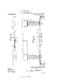
- Figure 1 represents a side view of one corner of the bedstead and mattress supporting frame provided with my device for yieldingly supporting a mattress frame.
- Fig. 2 is an end View of the device for yieldingly supporting one end of the mattress supporting frame from a bedstead and the mechanism for removably securing said device to the side rails of the bedstead.
- F 3 is a plan view of the fastening mechanism, a side view of which is shown in Fig. 2.
- Fig. 4 is a top view of one of the spring retaining cup shaped disks in connection with one of the mattress supporting springs; and Fig. 5 is a top View of the device shown in Fig. 4 with the spring and central rod removed.
- the mattress supporting frame comprises two side rails 3, one of which only is shown in Fig. l and the respective ends of each side rail are provided with a vertical bracket 4, which is rigidly secured thereto in the ordinary manner.
- Patented J nne M 1913 Patented J nne M 1913.
- mattress frame which is of ordinary con struction and is adapted to be connected with the side bars of the mattress frame in the ordinary manner.
- the several springs 7 are in'closed at their respective ends by cup shaped disks 8 and said disks are each provided with a central aperture 9 for the reception of the vertical rods 10, and the vertical rods 10 are colinected at their respective ends with the brackets 4, and are adapted to move upwardly and downwardly with said brackets.
- the upper ends of the rods 10 are connected with the upper ends of the brackets by pins,
- the rods 10 are retained in place in a true vertical position by said brackets 4 and the disks 8 are retained in place by said rods which pass through the central apertures therein and the respective ends of said springs 7 are retained in place by said cup-shaped disks whereby all the said parts cooperate to re tain said springs in their proper relative position to the mattress and mattress supporting frame.
- the spring supporting members 12 at the respective ends of the bedstead are secured to the side rails 2 of the bedstead by the angular brackets 13, which extend across the upper surface of the side rails 2, thence down their outer sides and thence beneath their lower edge, as shown in Fig. 2.
- the members 12 are preferably formed in two separate parts which are connected by clamping members 1-1, let, and bolts 15, 15 and 16.
- the clamping members 14, 1 are permanently connected at one end to the members 12 by the bolts 15, while the opposite ends of said members 14: are ad justably connected together by said bolts 16 operating in the elongated slots 17.
- the nut 18 is turned back on said bolt 16, when said members 12 are separated slightly, whereby the lower arms 19 of the brackets 13 are free to be brought beneath the lower edge of the rails 2. W hen this is done, said arms 19 are drawn toward each other and beneath the lower edge of the side rails 2.
- each bar comprising two separable members adj ustably connected together, each separable member being provided with angular brackets adapted to extend across and rest upon the upper horizontal surface down past the exterior vertical surface to and beneath the lower edge of the respective side rails of the bedstead, means for adjustably connecting the inner ends of said separable ;1nembers together, a compression spring supported in a vertical position'from each of said separable members within the side rails of the bedstead, and a mattress frame sup .ported from the upper ends of said springs.
- each bar comprising two separable members adjustably connected together, each separable member being provided with angular brackets adapted to extend across and ,rest upon the upper horizontal surface down past the exterior vertical surface to and beneath the lower edge of the respective side .rails of the bedstead, means for adjustably iconnecting the inner ends of said separable zmembers together, a compression spring supported in a vertical position from each of said separable members within the side rails ;of the bedstead, a cup-shaped disk inclosing the respective ends of each of said springs, ieach disk being provided with a central aperture, a rod centrally located within each of said springs, having its respective ends 'within the apertures of said cup-shaped disks, a corner bracket forming an integral part of said mattress frame located at its respective corners, said bracket being adapted to support a mattress fabric from and above said frame and
Landscapes
- Mattresses And Other Support Structures For Chairs And Beds (AREA)
Description
R. G. MARQUARDT. MATTRESS FRAME.
APPLICATION FILED MAR.13, 1918.
1,064,5 10, Patented June 10,1913.
2 SHEETS-SHEET l.
R. G. MARQUARDT. MATTRESS FRAME.
APPLICATION FILED MAR.13, 1913.
Patented June 10,1913.
2 SHEETS-SHEET 2.
Game/t 5 COLUMBXA I-LANOGRAPH CO.,WASHINOTON. D c,
ill ES A N FTC.
REINI-IOLD Gr. MARQUARDT, OF MILWAUKEE, WISCONSIN, ASSIGNOR- TO MILWAUKEE WOVEN WIRE WORKS, OF MILWAUKEE, \VISCONSIN, A CORPORATION OF WIS- CONSIN.
MATTRESS-FRAME.
Application filed March 13, 1913.
To all whom it may concern Be it known that I, REINHOLD Gr. MAR- QUAIEDT, a citizen of the United States, residing at Milwaukee, county of Milwaukee, and State of Wisconsin, have invented new and useful Improvements in Mattress- Frames, of which the following is a specification.
My invention relates to improvements in devices for yieldingly supporting a mattress frame and spring from the side rails of a bedstead and it pertains more especially, among other things, 1st, to the device for detachably connecting the yielding mecha nism of the mattress supporting frame to the side rails of the bed-stead, and 2nd, to the device for securely retaining the spiral springs in place between the bearing surfaces of the bed-stead and the four corners of the mattress supporting frame.
My invention is further explained by reference to the accompanying drawings in which Figure 1 represents a side view of one corner of the bedstead and mattress supporting frame provided with my device for yieldingly supporting a mattress frame. Fig. 2 is an end View of the device for yieldingly supporting one end of the mattress supporting frame from a bedstead and the mechanism for removably securing said device to the side rails of the bedstead. F 3 is a plan view of the fastening mechanism, a side view of which is shown in Fig. 2.
Fig. 4 is a top view of one of the spring retaining cup shaped disks in connection with one of the mattress supporting springs; and Fig. 5 is a top View of the device shown in Fig. 4 with the spring and central rod removed.
Like parts are identified by the same reference numerals throughout the several views.
1 represents one of the corner posts of a bedstead of ordinary construction.
2 is a side rail of the bedstead, which is preferably made of angle iron and the same is connected with the posts in the ordinary manner. The mattress supporting frame comprises two side rails 3, one of which only is shown in Fig. l and the respective ends of each side rail are provided with a vertical bracket 4, which is rigidly secured thereto in the ordinary manner.
5 represents one of the end bars of the Specification of Letters Patent.
Patented J nne M 1913.
Serial No. 753,940.
mattress frame, which is of ordinary con struction and is adapted to be connected with the side bars of the mattress frame in the ordinary manner.
6 represents a portion of the mattress supporting spring, which is adapted to be connected at its respective ends with the end bars 5 of the spring supporting frame.
It will be understood that the parts thus far described are of ordinary construction, and invention herein is predicated more especially, upon the device for yieldingly supporting the mattress supporting frame from the side rails 2 of the bedstead, whereby when pressure is applied to the upper sur face of the spring 6, said springs together with the frame members 5, brackets 4 and the side rails 3 are adapted to be moved downwardly past the side rails 2 against the resistance of the four spiral springs 7, one of which is connected, as shown in Figs. 1 and 2, with each corner of the bedstead and mattress supporting frame.
The several springs 7 are in'closed at their respective ends by cup shaped disks 8 and said disks are each provided with a central aperture 9 for the reception of the vertical rods 10, and the vertical rods 10 are colinected at their respective ends with the brackets 4, and are adapted to move upwardly and downwardly with said brackets. The upper ends of the rods 10 are connected with the upper ends of the brackets by pins,
nuts or other equivalent devices 11. It will now be understood that when a downward pressure is applied upon the surface of the mattress, the rods 10 will move downwardly with the brackets 4 that the lower portions of said brackets are located within and move downwardly past the under edge of the spring supporting members 12, while the lower end of the spring, together with the disks 8 will remain at rest upon the upper side of said members 12. As soon as the pressure upon the surface of the mattress is removed, said mattress and its supporting frame will be thrown upwardly by the recoil of said spiral spring 7. The rods 10 are retained in place in a true vertical position by said brackets 4 and the disks 8 are retained in place by said rods which pass through the central apertures therein and the respective ends of said springs 7 are retained in place by said cup-shaped disks whereby all the said parts cooperate to re tain said springs in their proper relative position to the mattress and mattress supporting frame. The spring supporting members 12 at the respective ends of the bedstead are secured to the side rails 2 of the bedstead by the angular brackets 13, which extend across the upper surface of the side rails 2, thence down their outer sides and thence beneath their lower edge, as shown in Fig. 2.
The members 12 are preferably formed in two separate parts which are connected by clamping members 1-1, let, and bolts 15, 15 and 16. The clamping members 14, 1 1, are permanently connected at one end to the members 12 by the bolts 15, while the opposite ends of said members 14: are ad justably connected together by said bolts 16 operating in the elongated slots 17. Thus it isobvious that when it is desired to connect the spring supporting members with the side rails 2 of the bedstead, the nut 18 is turned back on said bolt 16, when said members 12 are separated slightly, whereby the lower arms 19 of the brackets 13 are free to be brought beneath the lower edge of the rails 2. W hen this is done, said arms 19 are drawn toward each other and beneath the lower edge of the side rails 2. The nut 18 is then turned back on the bolt 16, whereby said clamping members 14: are rigidly clamped together, and whereby the brackets 13 are securely retained in place around and beneath said side rails. To permit of the required lateral movement of the members 12 when engaging the arms 19 beneath the lower edges of the side rails 2 without mov ing or inclining the rods 10, I have provided an elongated slot in the outer ends of said members 12 for the reception of the lower end of said rods 10, whereby the members 12 are free to be moved toward the right and left for the purpose stated" Experience has demonstrated that when any one or more of the springs 7 have been suddenly released from pressure, the m0- mentum of the mattress and supporting frame is such, as heretofore constructed, to lift the mattress supporting frame from the side rails of the bedstead. It will be obvious that by extending the arms 19 beneath the lower edge of the side rails 2, the mattress supporting frame will be rigidly retained in place upon the side rails of the bedstead and cannot be thrown upwardly i away from the rails by the momentum of.
the mattress supporting frame.
I-Iavmg thus descrlbed my invention, what I claim as new, and desire to secure by Letters Patent, is
1. In a device of the described class, the combination with the side rails of a bedstead, of a pair of transversely arranged bars, each bar comprising two separable members adj ustably connected together, each separable member being provided with angular brackets adapted to extend across and rest upon the upper horizontal surface down past the exterior vertical surface to and beneath the lower edge of the respective side rails of the bedstead, means for adjustably connecting the inner ends of said separable ;1nembers together, a compression spring supported in a vertical position'from each of said separable members within the side rails of the bedstead, and a mattress frame sup .ported from the upper ends of said springs.
2. In a device of the described class, the combination with the side rails of a bed stead, of a pair of transversely arranged bars, each bar comprising two separable members adjustably connected together, each separable member being provided with angular brackets adapted to extend across and ,rest upon the upper horizontal surface down past the exterior vertical surface to and beneath the lower edge of the respective side .rails of the bedstead, means for adjustably iconnecting the inner ends of said separable zmembers together, a compression spring supported in a vertical position from each of said separable members within the side rails ;of the bedstead, a cup-shaped disk inclosing the respective ends of each of said springs, ieach disk being provided with a central aperture, a rod centrally located within each of said springs, having its respective ends 'within the apertures of said cup-shaped disks, a corner bracket forming an integral part of said mattress frame located at its respective corners, said bracket being adapted to support a mattress fabric from and above said frame and to form supporting bearings for said vertical rods, said Tbrackets being adapted to support said rods, esaid rods to hold said cup-shaped disks, :while said disks in turn retain the respective ends of said springs in place, all substantially as and for the purpose specified.
In testimony whereof I atfix my signature in the presence of two witnesses.
REINHOLD G. MARQUARDT.
I IVitnesses:
HELEN O. VAN RYN, IRMA 'D. BREMER.
Copies of this patent may be obtained for ,five cents each. by addressing the Commissioner of Patents, Washington, D. 0.
Priority Applications (1)
| Application Number | Priority Date | Filing Date | Title |
|---|---|---|---|
| US75394013A US1064510A (en) | 1913-03-13 | 1913-03-13 | Mattress-frame. |
Applications Claiming Priority (1)
| Application Number | Priority Date | Filing Date | Title |
|---|---|---|---|
| US75394013A US1064510A (en) | 1913-03-13 | 1913-03-13 | Mattress-frame. |
Publications (1)
| Publication Number | Publication Date |
|---|---|
| US1064510A true US1064510A (en) | 1913-06-10 |
Family
ID=3132753
Family Applications (1)
| Application Number | Title | Priority Date | Filing Date |
|---|---|---|---|
| US75394013A Expired - Lifetime US1064510A (en) | 1913-03-13 | 1913-03-13 | Mattress-frame. |
Country Status (1)
| Country | Link |
|---|---|
| US (1) | US1064510A (en) |
-
1913
- 1913-03-13 US US75394013A patent/US1064510A/en not_active Expired - Lifetime
Similar Documents
| Publication | Publication Date | Title |
|---|---|---|
| US1064510A (en) | Mattress-frame. | |
| US522014A (en) | George hunzinger | |
| US815610A (en) | Mattress. | |
| US908689A (en) | Lawn-swing. | |
| US874421A (en) | Baby-crib. | |
| US792520A (en) | Spring-bottom for beds. | |
| US399902A (en) | Spring-bed | |
| US1143342A (en) | Bed. | |
| US149547A (en) | Improvement in spring bed-bottoms | |
| US788825A (en) | Spring-bottom. | |
| US341494A (en) | Spring bed-bottom | |
| US279188A (en) | Spring-bed | |
| US986836A (en) | Corner bed-spring. | |
| US258595A (en) | phillips | |
| US331599A (en) | Spring-bed | |
| US240903A (en) | Cot-bed | |
| US600481A (en) | Self-leveling table | |
| US133090A (en) | Improvement in bed-bottoms | |
| US162096A (en) | Improvement in bed-bottoms | |
| US1018865A (en) | Bed-spring. | |
| US1341714A (en) | Spring-bed | |
| US264760A (en) | Geqege f | |
| US147778A (en) | Improvement in bed-bottoms | |
| US153547A (en) | Improvement in spring-chairs | |
| US1424853A (en) | roever |