US10569359B2 - Method for cutting out a section of a workpiece using a laser beam, and an associated laser cutting machine - Google Patents
Method for cutting out a section of a workpiece using a laser beam, and an associated laser cutting machine Download PDFInfo
- Publication number
- US10569359B2 US10569359B2 US15/292,579 US201615292579A US10569359B2 US 10569359 B2 US10569359 B2 US 10569359B2 US 201615292579 A US201615292579 A US 201615292579A US 10569359 B2 US10569359 B2 US 10569359B2
- Authority
- US
- United States
- Prior art keywords
- drive
- target values
- workpiece
- drive axis
- low
- Prior art date
- Legal status (The legal status is an assumption and is not a legal conclusion. Google has not performed a legal analysis and makes no representation as to the accuracy of the status listed.)
- Active, expires
Links
- 238000003698 laser cutting Methods 0.000 title claims abstract description 61
- 238000000034 method Methods 0.000 title claims abstract description 20
- 238000011144 upstream manufacturing Methods 0.000 claims description 11
- 238000012546 transfer Methods 0.000 claims description 6
- 238000001914 filtration Methods 0.000 claims description 3
- 230000001934 delay Effects 0.000 description 4
- 230000003111 delayed effect Effects 0.000 description 4
- 238000012545 processing Methods 0.000 description 4
- 230000001133 acceleration Effects 0.000 description 2
- 238000004364 calculation method Methods 0.000 description 2
- 230000004069 differentiation Effects 0.000 description 2
- 238000013459 approach Methods 0.000 description 1
- 230000008014 freezing Effects 0.000 description 1
- 238000007710 freezing Methods 0.000 description 1
- 239000011159 matrix material Substances 0.000 description 1
- 238000012986 modification Methods 0.000 description 1
- 230000004048 modification Effects 0.000 description 1
- 230000008569 process Effects 0.000 description 1
- 230000001360 synchronised effect Effects 0.000 description 1
Images


Classifications
-
- B—PERFORMING OPERATIONS; TRANSPORTING
- B23—MACHINE TOOLS; METAL-WORKING NOT OTHERWISE PROVIDED FOR
- B23K—SOLDERING OR UNSOLDERING; WELDING; CLADDING OR PLATING BY SOLDERING OR WELDING; CUTTING BY APPLYING HEAT LOCALLY, e.g. FLAME CUTTING; WORKING BY LASER BEAM
- B23K26/00—Working by laser beam, e.g. welding, cutting or boring
- B23K26/08—Devices involving relative movement between laser beam and workpiece
- B23K26/0869—Devices involving movement of the laser head in at least one axial direction
- B23K26/0876—Devices involving movement of the laser head in at least one axial direction in at least two axial directions
-
- B—PERFORMING OPERATIONS; TRANSPORTING
- B23—MACHINE TOOLS; METAL-WORKING NOT OTHERWISE PROVIDED FOR
- B23K—SOLDERING OR UNSOLDERING; WELDING; CLADDING OR PLATING BY SOLDERING OR WELDING; CUTTING BY APPLYING HEAT LOCALLY, e.g. FLAME CUTTING; WORKING BY LASER BEAM
- B23K26/00—Working by laser beam, e.g. welding, cutting or boring
- B23K26/08—Devices involving relative movement between laser beam and workpiece
- B23K26/083—Devices involving movement of the workpiece in at least one axial direction
- B23K26/0853—Devices involving movement of the workpiece in at least in two axial directions, e.g. in a plane
-
- B—PERFORMING OPERATIONS; TRANSPORTING
- B23—MACHINE TOOLS; METAL-WORKING NOT OTHERWISE PROVIDED FOR
- B23K—SOLDERING OR UNSOLDERING; WELDING; CLADDING OR PLATING BY SOLDERING OR WELDING; CUTTING BY APPLYING HEAT LOCALLY, e.g. FLAME CUTTING; WORKING BY LASER BEAM
- B23K26/00—Working by laser beam, e.g. welding, cutting or boring
- B23K26/36—Removing material
- B23K26/38—Removing material by boring or cutting
Definitions
- the present invention relates to methods and apparatuses for cutting out a workpiece section along a target path from a plate-shaped workpiece using a laser beam of a laser cutting machine.
- a target position of a tool can be reached by various combinations of the movements along the redundant axes.
- one machine component can be the sluggish (heavy) coarse axis component, having a large range of motion along the axis for movement over the workpiece (in the order of magnitude of meters) and another component, which can be highly accelerated, can be the (light) fine axis component having a small range of motion (in the order of magnitude of several centimeters to a few tens of centimeters) over the same axis. Movement in the components along the axis in concert can allow rapid travel down fine contours.
- the component for movement of the sheet acts as the coarse axis component
- the component for movement of the laser head acts as the fine axis component.
- German Patent Publication DE 103 55 614 A1 discloses filtering a target path using a low-pass filter and supplying the filtered target path to the coarse axis component to obtain target positions along the axis for each component so that the combined motion of the components produces the target path of laser processing.
- the difference between the filtered target path and the actual target path results in the target path for the fine axis component.
- the target values, which are strongly smoothed by the low-pass filter, are thus supplied to the less dynamic coarse axis component, and the difference between the smoothed target values of the coarse axis component and the target values of the axis pair are supplied to the more dynamic fine axis component.
- the target path is supplied to the system only after a delay to minimize the range of motion of the fine axis component, which enables higher accelerations for this component along the axis.
- the target path of the coarse axis component is thus closer to the target path of the overall system.
- Various embodiments disclosed herein provide methods and apparatuses for cutting out a workpiece section along a target path, to safely and reliably avoid the overlapping or entangling of cut-out workpiece sections with the remaining workpiece, i.e., to increase the process reliability during the outward transfer of cut-out workpiece sections, and to provide an associated laser cutting machine.
- Certain embodiments provide methods for cutting out a workpiece section along a target path from a plate-shaped workpiece using a laser beam of a laser cutting machine configured to emit a laser beam for cutting.
- the methods include determining, via at least one controller, first target values, X G , corresponding to positions of a workpiece and second target values, X S , corresponding to positions of a laser cutting head configured to emit the laser beam to align the laser beam onto the workpiece as a first drive moves the workpiece along a first drive axis and as a second drive configured to align the laser beam onto the workpiece contemporaneously moves the laser cutting head along the first drive axis as the first drive moves the workpiece so at to cause the laser beam to traverse the target path along the workpiece.
- the methods further include causing, the first drive to drive the workpiece to move, along at least a portion of the first target values, X G .
- the methods also include causing the second drive to drive the laser cutting head to move along at least a portion of the second target values, X S .
- the methods include setting the first target values X G to a constant drive axis target value via the at least one controller from a point in time before the laser beam reaches a cutting-out end position of the workpiece section and by at least a braking time of the first drive to bring the workpiece to a stop, so that after the braking of the first drive, the cutting out of the workpiece section is only still executed by the second drive continuing to drive the laser cutting head and the workpiece comes to a stop at latest at the cutting-out end position.
- the coarse axis is supplied a constant target value shortly before the cutting-out end position, so that the coarse axis and therefore the workpiece come to a stop and only the fine axis still moves during the cutting out of the workpiece section.
- the switchover point in time can be selected such that the workpiece comes to a standstill precisely at the moment at which the laser beam reaches the cutting-out end position. Due to the flying introduction of the final cut without prior stopping of the redundant axes, time is saved during each severing cut.
- low-frequency drive axis target values are filtered out of the drive axis target values using a low-pass filter and high-frequency drive axis target values are ascertained as the difference between the original drive axis target values and the low-frequency drive axis target values.
- This final cut initiated in a flying manner may be implemented particularly simply using a switch function, which stops the coarse axis at latest at the position at which the final cut begins.
- the drive axis target values for the first drive are switched to a constant drive axis target value by a switch arranged before the low-pass filter from the point in time before the cutting-out end position of the workpiece section by at least the braking time of the first drive, in accordance with particular implementations.
- a differentiation is made between a path division with and without delayed path execution.
- the switchover point in time is before the cutting-out end position of the workpiece section by at least two times the group delay of the low-pass filter.
- the switchover point in time is before the cutting-out end position of the workpiece section by at least one group delay of the low-pass filter.
- the invention also relates to a laser cutting machine for laser cutting of workpiece sections along a target path from a plate-shaped workpiece using a laser beam having a first drive for moving the workpiece at least along a first drive axis and a second drive for moving a laser cutting head, which aligns the laser beam onto the workpiece, at least along the first drive axis, and having a control device for movement division of drive axis target values of the target path of the laser beam into low-frequency drive axis target values of the first drive and high-frequency drive axis target values of the second drive, wherein the control device ascertains the high-frequency drive axis target values as the difference between the original drive axis target values and the low-frequency drive axis target values and, according to the invention, has an activatable transfer device, which transfers the drive axis target values for the first drive to a constant drive axis target value.
- the control device has a low-pass filter implemented, for example, as a linear-phase FIR filter, which filters the low-frequency drive axis target values out of the supplied drive axis target values, and a subtraction unit, which ascertains the high-frequency drive axis target values as the difference between the original drive axis target values and the low-frequency drive axis target values, and an activatable switch upstream of the low-pass filter as the transfer device, which in its one switch position relays the supplied drive axis target values and in its other switch position relays a constant drive axis target value to the low-pass filter.
- the switch is activated in a timely manner before the cutting-out end position by the machine control of the laser cutting machine, for example.
- a switch is introduced upstream the low-pass filter, which is flipped when the target value of the redundant axis pair has reached the position at which the final cut begins.
- the target position of the coarse axis is kept constant at the input of the low-pass filter, so that the coarse axis and therefore the workpiece come to a stop and only the fine axis still moves during the cutting out of the workpiece section.
- the supplied drive axis target values for the execution of the final cut are interpolated further by the machine control without interruption, but only used for the calculation of the target values of the fine axis.
- the length of the final cut has to be dimensioned in this case so that it is within the range of the fine axis.
- the path division uses a low-pass filter
- a differentiation is made between path division with and without delayed path execution, wherein the implementation according to the invention of a final cut introduced in a flying manner functions in the same manner in both variants.
- a linear-phase FIR filter is used as the low-pass filter, as a result of its properties, it thus lasts exactly two group delays of the filter from the point in time of flipping the switch until the coarse axis comes to a standstill. The soft braking of the coarse axis is automatically ensured in this case without complex auxiliary algorithms by the path division filter.
- the device can have a delay unit upstream of the subtraction unit, which chronologically delays the supplied drive axis target values by at least the group delay of the low-pass filter. If a linear-phase FIR filter is used as the low-pass filter, as a result of its properties, it thus lasts exactly one group delay of the filter from the point in time of flipping the switch until the coarse axis comes to a standstill. The soft braking of the coarse axis is automatically ensured in this case without complex auxiliary algorithms by the path division filter.
- the first drive is designed for moving the workpiece along two drive axes perpendicular to one another and the second drive is designed for moving the laser cutting head along the two drive axes.
- the device can have, for each of the two drive axes, a low-pass filter and a subtraction unit for the movement division of the drive axis target values of the target path into low-frequency drive axis target values of the coarse axes and high-frequency drive axis target values of the fine axes and an activatable switch upstream of the low-pass filter, which in one switch position relays the supplied drive axis target values and in another switch position relays a constant drive axis target value to the low-pass filter.
- the switches are activated, for example, by the machine control of the laser cutting machine in a timely manner before the cutting-out end position.
- particular embodiments of the invention also relate to a device for movement division of drive axis target values of the target path of a laser beam into low-frequency drive axis target values of a first drive and high-frequency drive axis target values of a second drive.
- the device has a low-pass filter, which filters the low-frequency drive axis target values out of the supplied drive axis target values, and has a subtraction unit, which ascertains the high-frequency drive axis target values as the difference between the original drive axis target values and the low-frequency drive axis target values.
- an activatable switch is upstream of the low-pass filter, which in its one switch position relays the supplied drive axis target values to the low-pass filter and in its other switch position relays a constant drive axis target value to the low-pass filter.
- particular embodiments of the invention also relates to a method for cutting out a workpiece section along a target path from a plate-shaped workpiece using a laser beam of a laser cutting machine, which has a first drive for moving the workpiece at least along a first drive axis, a second drive for moving a laser cutting head, which aligns the laser beam onto the workpiece, at least along the first drive axis, wherein drive axis target values of the target path of the laser beam are divided into drive axis target values for the first drive and drive axis target values for the second drive, and wherein from a point in time which is before the cutting-out end position of the workpiece section by at least the braking time of the first drive, the drive axis target values for the first drive are transferred to a constant drive axis target value, so that after the braking of the first drive, the cutting out of the workpiece section is only still executed by moving the laser cutting head and the workpiece comes to a stop at latest at the cutting-out end position.
- FIG. 1 shows a laser cutting machine having a workpiece movable along the X and Y axes, a laser cutting head movable along the X and Y axes, and a device for path division of the target path of the laser beam into a movement along the workpiece axes and a movement along the laser cutting head axes.
- FIG. 2A and FIG. 2B show a known path division device having a low-pass filter without time delay ( FIG. 2A ) and an associated path division ( FIG. 2B ) along the Y axis during the laser cutting of a square workpiece section.
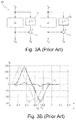
- FIG. 3A and FIG. 3B show a known path division device having a low-pass filter with time delay ( FIG. 3A ) and an associated path division ( FIG. 3B ) along the Y axis during the laser cutting of a square workpiece section.
- FIG. 4A and FIG. 4B show a path division device according to the invention having a low-pass filter without time delay ( FIG. 4A ) and an associated path division ( FIG. 4B ) along the Y axis during the laser cutting of a square workpiece section.
- FIG. 5A and FIG. 5B show a path division device according to the invention having a low-pass filter with time delay ( FIG. 5A ) and an associated path division ( FIG. 5B ) along the Y axis during the laser cutting of a square workpiece section.
- the laser cutting machine 1 shown in FIG. 1 is used for the laser cutting of workpiece sections 2 along a target path 3 from a plate-shaped workpiece (for example, sheet) 4 using a laser beam 5 .
- the laser cutting machine 1 comprises a first XY drive (“workpiece drive”) 6 for moving the workpiece 4 in the XY plane along the X and Y axes, a second XY drive (“laser cutting head drive”) 7 for moving a laser cutting head 8 , which aligns the laser beam 5 on the workpiece 4 , along the X and Y axes, and a machine controller 9 , which supplies the target values X S , Y S for the target path of the laser beam 5 on the workpiece 4 .
- the laser cutting machine 1 additionally has a device 10 for the movement division of the drive axis target values X S , Y S of the target path 3 of the laser beam 5 into low-frequency drive axis target values X G , Y G for the workpiece drive 6 and high-frequency drive axis target values X F , Y F for the laser cutting head drive 7 .
- FIG. 2A shows a known path division device 20 having a low-pass filter 11 without time delay and a subtraction unit 12 for each of the two drive axes X, Y.
- the low-pass filters 11 are linear-phase FIR filters having constant group delay and filter in each case the low-frequency drive axis target values X G , Y G out of the supplied drive axis target values X S , Y S and relay them to the workpiece drive 6 .
- the subtraction units 12 ascertain the high-frequency drive axis target values X F , Y F as the difference between the supplied drive axis target values X S , Y S and the filtered drive axis target values X G , Y G and relay them to the laser processing head drive 7 .
- the low-frequency drive axis target values X G , Y G which are strongly smoothed by the low-pass filters 11 , are thus supplied to the less dynamic coarse axes of the workpiece drive 6 , and the difference between the original drive axis target values X S , Y S and the smoothed drive axis target values X G , Y G of the coarse axis are supplied to the more dynamic fine axes of the laser cutting head drive 7 .
- FIG. 2B shows the time curve of the associated path division during the laser cutting of a square workpiece section 2 along the Y axis, i.e., the time curve of the supplied drive axis target values Y S (solid line), the drive axis target values Y G for the coarse axis (fine dashed line) and the drive axis target values Y F for the fine axis (dashed line).
- the coarse and fine axes also still run in opposite directions when the superimposed movement of the redundant coarse and fine axes is already completed. The remaining sheet thus still moves when the workpiece section 2 is already cut out. The risk of overlapping or entangling between the workpiece section 2 and the remaining sheet thus exists.
- the known path division device 20 ′ shown in FIG. 3A differs from the path division device 20 only in that the drive axis target values X S , Y S are supplied with a time delay to the subtraction units 12 using delay units 14 here.
- the target path of the coarse axis is closer to the target path of the overall system and, on the other hand, the range of motion of the fine axis required for the method is minimized, which enables higher accelerations for this axis.
- 3B shows the time curve of the associated path division during the laser cutting of a square workpiece section 2 along the Y axis, i.e., the time curve of the supplied drive axis target values Y S (fine dashed line), the delayed drive axis target values Y S ′ (solid line), the drive axis target values Y G for the coarse axis (dashed line) and the drive axis target values Y F for the fine axis (broken line).
- the coarse and fine axes also still run in opposite directions here when the superimposed movement of the redundant coarse and fine axes is already completed.
- the path division device 10 differs from the path division device 20 in that a switch 15 , which is activated by the machine control 9 , is arranged upstream of each of the low-pass filters 11 .
- the switches 15 relay in their one switch position the supplied drive axis target values X S , Y S and in their other switch position a constant drive axis target value X Sconst , Y Sconst to the respective low-pass filters 11 .
- FIG. 4B shows the associated path division during the laser cutting of a square workpiece section 2 along the Y axis, i.e., the time curve of the supplied drive axis target values Y S (solid line), the drive axis target values Y G for the coarse axis (solid line), and the drive axis target values Y F for the fine axis (dashed line).
- the final cut 13 of the workpiece section 2 i.e., the severing cut of the last contour section for cutting out the workpiece section 2 from the workpiece 4 , is initiated by switching over the switch 15 to the constant drive axis target values X Sconst , Y Sconst .
- this target position is kept constant (“frozen”) at the input of the low-pass filter 11 , i.e., the coarse axis is stopped at the position at which the final cut 13 begins.
- the target values for the execution of the final cut 13 are further interpolated by the machine control 9 without interruption and used for the calculation of the target values of the fine axis. From the point in time t A , the cutting out of the workpiece section 2 is increasingly performed by moving the fine axis or the laser cutting head 8 , while the coarse axis or the workpiece 4 decelerate and come to a standstill precisely at the point in time t E at which the final cut 13 reaches the cutting-out end position F.
- the length of the final cut 13 has to be dimensioned in this case so that it is within the range of the fine axis.
- the linear-phase FIR low-pass filter 11 used, it lasts exactly two group delays of the low-pass filter 11 from the point in time of flipping the switch 15 until the coarse axis comes to a standstill.
- the braking time for the execution of the final cut 13 therefore has to be at least two group delays. The soft braking of the coarse axis is ensured automatically in this case without complex auxiliary algorithms by the low-pass filter 11 .
- the path division device 10 ′ according to the invention shown in FIG. 5A differs from the path division device 10 in that the drive axis target values X S , Y S are supplied with a time delay to the subtraction units 12 using delay units 14 .
- FIG. 5B shows the associated path division during the laser cutting of a square workpiece section 2 along the Y axis, i.e., the time curve of the supplied drive axis target values Y S (light dashed line), the delayed drive axis target values Y S′ (solid line), the drive axis target values Y G for the coarse axis (dark dashed line) and the drive axis target values Y F for the fine axis (broken line).
- the final cut 13 is initiated by switching over the switch 15 to the constant drive axis target values X Gconst , Y Gconst , so that the cutting out of the workpiece section 2 is only still performed by moving the fine axis or the laser cutting head 8 and the coarse axis or the workpiece 4 come to a standstill precisely at the point in time t E at which the final cut 13 reaches the cutting-out end position F.
- the braking time for the execution of the final cut 13 has to be at least one group delay.
- the switches 15 for switching over the target values can be implemented in the same manner in the machine control 9 as the low-pass filters 11 for the path division.
- the information about when the switches 15 have to be flipped and how strongly the velocity has to be reduced during the final cut 13 can advantageously be calculated via a user interface (Numeric Control Kernel-Original Equipment Manufacturer interface (“NCK-OEM interface”) or via suitable synchronous actions, which are incorporated at a corresponding point in the NC program of the workpiece processing.
- NCK-OEM interface Numeric Control Kernel-Original Equipment Manufacturer interface
- offset values X Soffset , Y Soffset can optionally additionally also be added to the target values.
- the location of the cut-out workpiece section 2 in relation to the cutting matrix during the cutting out can be manipulated by these offset values.
- the adding is performed—like the freezing of the drive axis target values X S , Y S —in a “hard” manner.
- the offset values are retracted again when switching on the coarse axes using the switches 15 .
Landscapes
- Physics & Mathematics (AREA)
- Optics & Photonics (AREA)
- Engineering & Computer Science (AREA)
- Plasma & Fusion (AREA)
- Mechanical Engineering (AREA)
- Laser Beam Processing (AREA)
Applications Claiming Priority (4)
| Application Number | Priority Date | Filing Date | Title |
|---|---|---|---|
| DE102014207170.4 | 2014-04-15 | ||
| DE102014207170.4A DE102014207170B4 (de) | 2014-04-15 | 2014-04-15 | Verfahren zum Freischneiden eines Werkstückteils mittels eines Laserstrahls und zugehörige Laserschneidmaschine |
| DE102014207170 | 2014-04-15 | ||
| PCT/EP2015/057936 WO2015158647A1 (de) | 2014-04-15 | 2015-04-13 | Verfahren zum freischneiden eines werkstückteils mittels eines laserstrahls und zugehörige laserschneidmaschine |
Related Parent Applications (1)
| Application Number | Title | Priority Date | Filing Date |
|---|---|---|---|
| PCT/EP2015/057936 Continuation WO2015158647A1 (de) | 2014-04-15 | 2015-04-13 | Verfahren zum freischneiden eines werkstückteils mittels eines laserstrahls und zugehörige laserschneidmaschine |
Publications (2)
| Publication Number | Publication Date |
|---|---|
| US20170028508A1 US20170028508A1 (en) | 2017-02-02 |
| US10569359B2 true US10569359B2 (en) | 2020-02-25 |
Family
ID=53016584
Family Applications (1)
| Application Number | Title | Priority Date | Filing Date |
|---|---|---|---|
| US15/292,579 Active 2036-11-20 US10569359B2 (en) | 2014-04-15 | 2016-10-13 | Method for cutting out a section of a workpiece using a laser beam, and an associated laser cutting machine |
Country Status (6)
| Country | Link |
|---|---|
| US (1) | US10569359B2 (pl) |
| EP (1) | EP3131695B1 (pl) |
| CN (1) | CN106232284B (pl) |
| DE (1) | DE102014207170B4 (pl) |
| PL (1) | PL3131695T3 (pl) |
| WO (1) | WO2015158647A1 (pl) |
Families Citing this family (3)
| Publication number | Priority date | Publication date | Assignee | Title |
|---|---|---|---|---|
| CN109890553B (zh) | 2016-08-28 | 2022-05-17 | Acs 运动控制有限公司 | 用于激光机械加工多个相对较大工件的方法及系统 |
| JP7438009B2 (ja) * | 2020-04-28 | 2024-02-26 | 浜松ホトニクス株式会社 | レーザ加工装置 |
| CN112373016B (zh) * | 2020-10-23 | 2023-02-17 | 杭州德迪智能科技有限公司 | 三维层叠造型方法、装置、电子装置和存储介质 |
Citations (9)
| Publication number | Priority date | Publication date | Assignee | Title |
|---|---|---|---|---|
| DE4123323A1 (de) | 1991-07-13 | 1993-01-21 | Andreas Ehlerding | Werkzeugtraeger |
| US5751585A (en) * | 1995-03-20 | 1998-05-12 | Electro Scientific Industries, Inc. | High speed, high accuracy multi-stage tool positioning system |
| CN1213440A (zh) | 1996-03-12 | 1999-04-07 | 电科学工业公司 | 多刀具定位系统 |
| DE10355614A1 (de) | 2003-11-28 | 2005-07-07 | Siemens Ag | Einrichtung und Verfahren zur Bewegungsaufteilung einer Bewegung eines Maschinenteils entlang einer Antriebsachse einer Werkzeug- oder Produktionsmaschine |
| WO2011026486A1 (de) | 2009-09-04 | 2011-03-10 | Trumpf Werkzeugmaschinen Gmbh & Co. Kg | Laserbearbeitungsmaschine mit redundanten achsen |
| CN102015191A (zh) | 2008-05-08 | 2011-04-13 | 通快机床两合公司 | 具有扩展的工作空间的激光加工机 |
| CN102066036A (zh) | 2008-06-17 | 2011-05-18 | 伊雷克托科学工业股份有限公司 | 在多头激光机械加工系统中沿着共用夹具的行进方向消除头对头偏差 |
| WO2011131507A1 (de) | 2010-04-23 | 2011-10-27 | Osram Opto Semiconductors Gmbh | Verfahren und vorrichtung zur bearbeitung eines werkstückes mit einem laser |
| DE102011088673A1 (de) | 2011-12-15 | 2013-06-20 | Trumpf Werkzeugmaschinen Gmbh + Co. Kg | Werkzeugmaschine und Verfahren zur Bearbeitung von plattenförmigen Werkstücken |
-
2014
- 2014-04-15 DE DE102014207170.4A patent/DE102014207170B4/de not_active Expired - Fee Related
-
2015
- 2015-04-13 CN CN201580019825.0A patent/CN106232284B/zh active Active
- 2015-04-13 WO PCT/EP2015/057936 patent/WO2015158647A1/de not_active Ceased
- 2015-04-13 EP EP15719421.8A patent/EP3131695B1/de active Active
- 2015-04-13 PL PL15719421T patent/PL3131695T3/pl unknown
-
2016
- 2016-10-13 US US15/292,579 patent/US10569359B2/en active Active
Patent Citations (14)
| Publication number | Priority date | Publication date | Assignee | Title |
|---|---|---|---|---|
| DE4123323A1 (de) | 1991-07-13 | 1993-01-21 | Andreas Ehlerding | Werkzeugtraeger |
| US5574348A (en) | 1991-07-13 | 1996-11-12 | Ehlerding; Andreas | Tool support |
| US5751585A (en) * | 1995-03-20 | 1998-05-12 | Electro Scientific Industries, Inc. | High speed, high accuracy multi-stage tool positioning system |
| US5798927A (en) | 1995-03-20 | 1998-08-25 | Electro Scientific Industries, Inc. | Apparatus and method for coordinating the movements of stages in a multi-stage multi-rate positioner system |
| CN1213440A (zh) | 1996-03-12 | 1999-04-07 | 电科学工业公司 | 多刀具定位系统 |
| US6982536B2 (en) | 2003-11-28 | 2006-01-03 | Siemens Aktiengesellschaft | Device and method for apportioning a movement of a machine element along a drive axis of a machine tool or production machine |
| DE10355614A1 (de) | 2003-11-28 | 2005-07-07 | Siemens Ag | Einrichtung und Verfahren zur Bewegungsaufteilung einer Bewegung eines Maschinenteils entlang einer Antriebsachse einer Werkzeug- oder Produktionsmaschine |
| CN102015191A (zh) | 2008-05-08 | 2011-04-13 | 通快机床两合公司 | 具有扩展的工作空间的激光加工机 |
| CN102066036A (zh) | 2008-06-17 | 2011-05-18 | 伊雷克托科学工业股份有限公司 | 在多头激光机械加工系统中沿着共用夹具的行进方向消除头对头偏差 |
| WO2011026486A1 (de) | 2009-09-04 | 2011-03-10 | Trumpf Werkzeugmaschinen Gmbh & Co. Kg | Laserbearbeitungsmaschine mit redundanten achsen |
| CN102574240A (zh) | 2009-09-04 | 2012-07-11 | 通快机床两合公司 | 具有冗余轴的激光加工机 |
| WO2011131507A1 (de) | 2010-04-23 | 2011-10-27 | Osram Opto Semiconductors Gmbh | Verfahren und vorrichtung zur bearbeitung eines werkstückes mit einem laser |
| US20130126491A1 (en) * | 2010-04-23 | 2013-05-23 | Osram Opto Semiconductors Gmbh | Method and Device for Machining a Workpiece by Means of a Laser |
| DE102011088673A1 (de) | 2011-12-15 | 2013-06-20 | Trumpf Werkzeugmaschinen Gmbh + Co. Kg | Werkzeugmaschine und Verfahren zur Bearbeitung von plattenförmigen Werkstücken |
Non-Patent Citations (2)
| Title |
|---|
| International Search Report for corresponding PCT Application No. PCT/EP2015/057936, dated Aug. 28, 2015, 4 pages. |
| Office Action in Chinese Application No. 201580019825.0, dated Sep. 4, 2017, 28 pages (with English translation). |
Also Published As
| Publication number | Publication date |
|---|---|
| WO2015158647A1 (de) | 2015-10-22 |
| EP3131695B1 (de) | 2019-06-05 |
| PL3131695T3 (pl) | 2019-12-31 |
| DE102014207170B4 (de) | 2016-09-22 |
| DE102014207170A1 (de) | 2015-10-29 |
| CN106232284B (zh) | 2019-07-09 |
| EP3131695A1 (de) | 2017-02-22 |
| US20170028508A1 (en) | 2017-02-02 |
| CN106232284A (zh) | 2016-12-14 |
Similar Documents
| Publication | Publication Date | Title |
|---|---|---|
| US10569359B2 (en) | Method for cutting out a section of a workpiece using a laser beam, and an associated laser cutting machine | |
| DE102015103047B3 (de) | Initiale Abstandseinnahme für die Laserbearbeitung | |
| US9494929B2 (en) | Numerical controller having program restart function | |
| US7899575B2 (en) | Machine tool and method for processing a workpiece | |
| US20130240227A1 (en) | Method for operating a machine tool, projection device for a machine tool and machine tool with such a projection device | |
| SE1650545A1 (en) | Method and system for controlling platooning operation of a platoon of vehicles along a road | |
| CN104942453A (zh) | 激光加工装置 | |
| US20180339457A1 (en) | Three-dimensional laminating and shaping apparatus, control method of three-dimensional laminating and shaping apparatus, and control program of three-dimensional laminating and shaping apparatus | |
| US10814432B2 (en) | Unloading a cut-free workpiece part during machining | |
| JP5980977B1 (ja) | 絶対位置検出器を使用した機械座標値の再確立を行う数値制御装置 | |
| TWI632768B (zh) | 馬達控制裝置 | |
| WO2011117915A1 (ja) | 数値制御装置及び数値制御方法 | |
| US9841746B2 (en) | Numerical controller having function of controlling speed by superimposed control | |
| CN107457793B (zh) | 利用多机器人动态用户框进行动态激光触摸感测 | |
| JP2021051568A (ja) | 数値制御装置 | |
| JP6632710B2 (ja) | 機械制御部のためのフィルタ切り換え方法、プログラム、機械の制御ユニットおよび機械 | |
| JP6514004B2 (ja) | ギャップ制御機能を備えたレーザ加工機及びその制御装置 | |
| EP4613422A1 (en) | Gantry loader control method | |
| CN106232289B (zh) | 用于借助激光束激光加工工件的方法及相应的激光加工机 | |
| WO2020241905A1 (ja) | 制御装置、制御方法およびプログラム | |
| JP2015170310A (ja) | 準備動作を含む同期制御装置 | |
| JP2011164977A (ja) | 数値制御装置付き板材加工機の安全運転方法 | |
| US20200079277A1 (en) | Assistance method for a light control system in a motor vehicle, light control system, computer program product, and computer-readable medium | |
| JP2014108454A (ja) | レーザ加工機 | |
| JP7398947B2 (ja) | モータ制御装置 |
Legal Events
| Date | Code | Title | Description |
|---|---|---|---|
| AS | Assignment |
Owner name: TRUMPF WERKZEUGMASCHINEN GMBH + CO. KG, GERMANY Free format text: ASSIGNMENT OF ASSIGNORS INTEREST;ASSIGNORS:RENZ, BERND HERMANN;SCHMAUDER, FRANK;PFISTERER, DIETER;AND OTHERS;REEL/FRAME:040343/0807 Effective date: 20161026 |
|
| STPP | Information on status: patent application and granting procedure in general |
Free format text: DOCKETED NEW CASE - READY FOR EXAMINATION |
|
| STPP | Information on status: patent application and granting procedure in general |
Free format text: NON FINAL ACTION MAILED |
|
| STPP | Information on status: patent application and granting procedure in general |
Free format text: RESPONSE TO NON-FINAL OFFICE ACTION ENTERED AND FORWARDED TO EXAMINER |
|
| STPP | Information on status: patent application and granting procedure in general |
Free format text: NOTICE OF ALLOWANCE MAILED -- APPLICATION RECEIVED IN OFFICE OF PUBLICATIONS |
|
| STPP | Information on status: patent application and granting procedure in general |
Free format text: PUBLICATIONS -- ISSUE FEE PAYMENT VERIFIED |
|
| STCF | Information on status: patent grant |
Free format text: PATENTED CASE |
|
| MAFP | Maintenance fee payment |
Free format text: PAYMENT OF MAINTENANCE FEE, 4TH YEAR, LARGE ENTITY (ORIGINAL EVENT CODE: M1551); ENTITY STATUS OF PATENT OWNER: LARGE ENTITY Year of fee payment: 4 |