EP3131695B1 - Verfahren und vorrichtung zum laser-schneiden - Google Patents
Verfahren und vorrichtung zum laser-schneiden Download PDFInfo
- Publication number
- EP3131695B1 EP3131695B1 EP15719421.8A EP15719421A EP3131695B1 EP 3131695 B1 EP3131695 B1 EP 3131695B1 EP 15719421 A EP15719421 A EP 15719421A EP 3131695 B1 EP3131695 B1 EP 3131695B1
- Authority
- EP
- European Patent Office
- Prior art keywords
- drive axis
- drive
- axis target
- target values
- low
- Prior art date
- Legal status (The legal status is an assumption and is not a legal conclusion. Google has not performed a legal analysis and makes no representation as to the accuracy of the status listed.)
- Active
Links
Images


Classifications
-
- B—PERFORMING OPERATIONS; TRANSPORTING
- B23—MACHINE TOOLS; METAL-WORKING NOT OTHERWISE PROVIDED FOR
- B23K—SOLDERING OR UNSOLDERING; WELDING; CLADDING OR PLATING BY SOLDERING OR WELDING; CUTTING BY APPLYING HEAT LOCALLY, e.g. FLAME CUTTING; WORKING BY LASER BEAM
- B23K26/00—Working by laser beam, e.g. welding, cutting or boring
- B23K26/08—Devices involving relative movement between laser beam and workpiece
- B23K26/0869—Devices involving movement of the laser head in at least one axial direction
- B23K26/0876—Devices involving movement of the laser head in at least one axial direction in at least two axial directions
-
- B—PERFORMING OPERATIONS; TRANSPORTING
- B23—MACHINE TOOLS; METAL-WORKING NOT OTHERWISE PROVIDED FOR
- B23K—SOLDERING OR UNSOLDERING; WELDING; CLADDING OR PLATING BY SOLDERING OR WELDING; CUTTING BY APPLYING HEAT LOCALLY, e.g. FLAME CUTTING; WORKING BY LASER BEAM
- B23K26/00—Working by laser beam, e.g. welding, cutting or boring
- B23K26/08—Devices involving relative movement between laser beam and workpiece
- B23K26/083—Devices involving movement of the workpiece in at least one axial direction
- B23K26/0853—Devices involving movement of the workpiece in at least in two axial directions, e.g. in a plane
-
- B—PERFORMING OPERATIONS; TRANSPORTING
- B23—MACHINE TOOLS; METAL-WORKING NOT OTHERWISE PROVIDED FOR
- B23K—SOLDERING OR UNSOLDERING; WELDING; CLADDING OR PLATING BY SOLDERING OR WELDING; CUTTING BY APPLYING HEAT LOCALLY, e.g. FLAME CUTTING; WORKING BY LASER BEAM
- B23K26/00—Working by laser beam, e.g. welding, cutting or boring
- B23K26/36—Removing material
- B23K26/38—Removing material by boring or cutting
Definitions
- the present invention relates to a method for cutting open a workpiece part along a closed nominal path from a plate-shaped workpiece by means of a laser beam of a laser cutting machine, which has a first drive for moving the workpiece at least along a first drive axis, a second drive for moving a laser beam on the Wherein the drive axis setpoint values of the desired path of the laser beam are divided into drive axis nominal values for the first drive and drive axis nominal values for the second drive, as well as a laser cutting machine suitable for performing the method for laser cutting workpiece parts along a self-contained Target path from a plate-shaped workpiece by means of a laser beam.
- Such a method for free cutting a workpiece part and such a laser cutting machine for machining workpieces are, for example, from WO 2011/026486 A1 known.
- the setpoint position of a tool can be achieved by various combinations of movements along the redundant axes.
- the movement of the sheet forms the Grobachse and the movement of the laser head forms the fine axis.
- a multiaxial movement unit is moved by means of a control in such a way that a guided processing unit including a laser cutting head moves on a desired path over a workpiece and the workpiece is processed by means of a laser beam.
- the desired trajectory is divided by the controller into a movement of the track-laying unit along its main axes and into a deflection of the processing unit about its additional axes, and the drives of the traversing and processing units are controlled accordingly by the controller.
- the desired path is supplied to the system only after a delay.
- the desired path of the Grobachse is closer to the desired path of the overall system.
- This object is achieved in that from a time which is at least the braking time of the first drive before Freitenendposition of the workpiece part, the drive axle setpoints for the first drive are converted to a constant drive axle setpoint, so that after braking the first drive, the free cutting of the workpiece part is carried out only by moving the laser cutting head and the workpiece comes to a halt at the latest at the Freitenendposition.
- the Grobachse is supplied shortly before the Freiauerendposition a constant setpoint, so that the Grobachse and thus the workpiece come to a halt and moves when cutting the workpiece part only the fine axis.
- the switching time is chosen such that the workpiece comes to a standstill just in the moment in which the laser beam reaches the Freiauerendposition. The flying initiation of the Final Cut without prior stopping of the redundant axes saves time with each cut.
- low frequency drive axle setpoint values are filtered out of the drive axle setpoint values by means of a low pass filter and high frequency drive axle setpoint values are determined as the difference between the original drive axle setpoint values and the low frequency drive axle setpoint values.
- This flying-initiated Final Cut can then be implemented particularly easily by means of a switching function that stops the Grobachse at the latest at the position at which the Final Cut begins.
- the drive axle setpoint values for the first drive are particularly preferably selected by a switch arranged upstream of the low-pass filter Time, which is at least the braking time of the first drive before the free cutting end position of the workpiece part, switched to a constant drive axle setpoint.
- the switchover time is at least twice the group delay of the low-pass filter before the free-cutting end position of the workpiece part.
- the switchover time is at least one group delay of the low-pass filter before the free-cutting end position of the workpiece part.
- the invention also relates to a laser cutting machine for laser cutting workpiece parts along a closed nominal path from a plate-shaped workpiece by means of a laser beam with a first drive for moving the workpiece at least along a first drive axis and a second drive for moving the laser beam the workpiece aligning laser cutting head at least along the first drive axis, and with a device for movement division of driving axis target values of the desired path of the laser beam in the low frequency drive axle setpoints of the first drive and high frequency drive axle setpoints of the second drive, the device the high frequency drive axle setpoints as the difference between the original drive axle setpoints and the Low-frequency drive axle setpoints determined and according to the invention has a controllable transfer device, the Drive axle setpoints for the first drive transferred to a constant drive axle setpoint.
- the device has a low-pass filter realized, for example, as a linear-phase FIR filter, which converts the low-frequency currents from the supplied drive axle setpoints Drive axle setpoint values, and a subtractor, which determines the high-frequency drive axle setpoint as the difference between the original drive axle setpoints and the low-frequency drive axle setpoints, and as a transfer means a controllable switch upstream of the low-pass filter, the one in its switching position, the input drive axle setpoints and in its other switching position a constant drive axle setpoint to the low pass filter forwards.
- the switch is activated, for example, by the machine control of the laser cutting machine in good time before the free-cutting end position.
- a switch is inserted in front of the low-pass filter, which switch is then switched over when the setpoint value of the redundant axis pair has reached the position at which the final cut begins.
- this target position of the Grobachse at the input of the low-pass filter is kept constant, so that the Grobachse and thus the workpiece come to a halt and only moves the fine axis when cutting free the workpiece part.
- the supplied drive axle setpoints for the execution of the Final Cut are further interpolated by the machine control without interruption, but only used for the calculation of the setpoints of the fine axis.
- the length of the Final Cut must be such that it is within the range of the fine axis.
- the device preferably has a decelerator upstream of the subtractor, which delays the supplied drive axle setpoint values by at least the group delay of the low-pass filter.
- a decelerator upstream of the subtractor which delays the supplied drive axle setpoint values by at least the group delay of the low-pass filter.
- the gentle deceleration of the Grobachse is automatically ensured by the web splitting filter without the need for additional additional algorithms.
- the first drive for moving the workpiece along two mutually perpendicular drive axes and the second drive for moving the laser cutting head along the two drive axes are formed.
- the device for both drive axles can each have a low-pass filter and a subtractor for the movement distribution of the drive axle setpoint values of the setpoint path into low-frequency drive axle setpoint values of the coarse axes and into high-frequency drive axle setpoint values of the fine axes and a controllable switch upstream of the low-pass filter, which in its one switch position feeds the drive axle setpoint values and in its other switching position forwards a constant drive axle setpoint to the low-pass filter.
- the switches are activated, for example, by the machine control of the laser cutting machine in good time before the free-cutting end position.
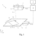
- laser cutting machine 1 is used for laser cutting of workpiece parts 2 along a desired path 3 from a plate-shaped workpiece (eg sheet metal) 4 by means of a laser beam.
- the laser cutting machine 1 includes a first XY ("workpiece drive”) drive 6 for moving the workpiece 4 in the XY plane along the X and Y axes, a second XY drive (“laser cutting head drive”) 7 for moving the laser beam 5 on the workpiece 4 aligning laser cutting head 8 along the X and Y axes, and a machine controller 9 , which supplies the target values XS , YS for the desired path of the laser beam 5 on the workpiece 4.
- first XY workpiece drive
- laser cutting head drive for moving the laser beam 5 on the workpiece 4 aligning laser cutting head 8 along the X and Y axes
- machine controller 9 which supplies the target values XS , YS for the desired path of the laser beam 5 on the workpiece 4.
- the laser cutting machine 1 also has a device 10 for the movement division of the drive axle setpoint values XS, YS of the setpoint path 3 of the laser beam 5 into low-frequency drive axle setpoint values XG , YG for the workpiece drive 6 and into high-frequency drive axle setpoint values XF , YF for the laser cutting head drive 7.
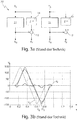
- Fig. 2a shows a known web splitting device 20 , each with a low-pass filter 11 without time delay and a subtractor 12 for both drive axes X, Y.
- the low-pass filter 11 are linear phase FIR filters with constant group delay and filter from the supplied drive axle setpoints XS, YS respectively the low-frequency drive axle setpoints XG, YG out and forward them to the workpiece drive 6 on.
- the subtractors 12 determine the high-frequency drive axle setpoint values XF, YF as the difference between the supplied drive axle setpoint values XS, YS and the filtered drive axle setpoint values XG, YG and forward them to the laser processing head drive 7.
- the low-frequency drive axle setpoint values XG, YG which are greatly smoothed by the low-pass filters 11 are thus fed to the less dynamic coarse axes of the workpiece drive 6, and the difference between the original drive axis setpoints XS, YS and the smoothed drive axis setpoint values XG, YG of the coarse axis becomes the higher dynamic fine axes of the laser cutting head drive 7 fed.
- Fig. 2b the time course of the associated path division during the laser cutting of a square workpiece part 2 along the Y-axis is shown, ie the time course of the supplied drive axle setpoint YS, the drive axle setpoint YG for the coarse and the drive axle setpoint YF for the fine axis. Due to the properties of the web splitting, the coarse and fine axes also run in opposite directions even if the superimposed movement of the redundant coarse and fine axes has already been completed. The residual sheet still moves when the workpiece part 2 is already cut free. As a result, there is a risk of overlapping or catching between the workpiece part 2 and the residual sheet.
- the in Fig. 3a shown known web splitting device 20 ' only in that here the drive axle setpoint values XS, YS are supplied by means of retarders 14 time delayed to the subtractors 12.
- the desired trajectory of the Grobachse is closer to the desired trajectory of the overall system and on the other hand minimizes the necessary for the process movement space of the fine axis, which allows higher accelerations for this axis.
- Fig. 3a shown known web splitting device 20 ' only in that here the drive axle setpoint values XS, YS are supplied by means of retarders 14 time delayed to the subtractors 12.
- 3b is the time course of the associated path division when laser cutting a square workpiece part 2 along the Y-axis shown, ie the time course of the input drive axle setpoint values YS, the delayed drive axle setpoint values YS ', the drive axle setpoint values YG for the coarse axle and the drive axle setpoint values YF for the fine axle.
- the coarse and fine axes continue to run in opposite directions even when the superimposed movement of the redundant coarse and fine axes has already been completed.
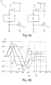
- the in Fig. 4a shown web partitioning device 10 characterized in that here the low-pass filters 11 each have a switch 15 is arranged upstream, which is controlled by the machine control 9.
- the switches 15 in their one shift position forward the supplied drive axle setpoint values XS, YS and in their other switching position a constant drive axle setpoint value XS const , YS const to the respective lowpass filters 11.
- Fig. 4b the associated path division during the laser cutting of a square workpiece part 2 along the Y axis is shown, ie the time profile of the supplied drive axle setpoint values YS, the drive axle setpoint values YG for the coarse axis and the drive axle setpoint values YF for the fine axis.
- time t A which is the braking time of the Grobachse before the Freiintroductoryendposition F of the workpiece part 2, the final cut 13 of the workpiece part 2, so the separation section of the last contour section for free cutting of the workpiece part 2 from the workpiece 4, by switching the switch 15 the constant drive axle setpoints XS const , YS const initiated.
- this desired position at the input of the low-pass filter 11 is kept constant ("frozen"), ie the coarse breeze is stopped at the position at which the final cut 13 begins.
- the setpoint values for the execution of the final cut 13 are further interpolated by the machine control 9 without interruption and used for the calculation of the setpoint values of the fine axis. From the time t A , the free cutting of the workpiece part 2 is increasingly carried out by moving the fine axis or the laser cutting head 8, while the coarse or the workpiece 4 decelerate and come to a standstill at the time t E , in which the Final Cut 13, the Free cut end position F reached.
- the length of the Final Cut 13 must be such that it is within the reach of the fine axis.
- the linear-phase FIR low-pass filter 11 Due to the characteristics of the linear-phase FIR low-pass filter 11 used, it takes from the time the switch 15 is turned over exactly two group delays of the low-pass filter 11 until the Grobachse comes to a standstill. Therefore, in this web splitting without time-delayed web execution, the braking time for the execution of the Final Cut 13 must be at least two group delays. The gentle deceleration of the Grobachse is automatically ensured by the low-pass filter 11 without complicated additional algorithms.
- Fig. 5a shown web splitting device 10 ' only in that here the drive axle setpoint values XS, YS delayed delays 14 are supplied to the subtractors 12.
- Fig. 5b the associated path division during the laser cutting of a square workpiece part 2 along the Y-axis is shown, ie the time course of the input drive axle setpoints YS, the delayed drive axle setpoints YS ', the drive axle setpoints YG for the coarse axle and the drive axle setpoints YF for the fine axle.
- the Final Cut 13 is initiated by switching the switch 15 to the constant drive axle setpoints XG const , YG const , so that the free cutting of the workpiece part 2 only by moving the fine axis or the laser cutting head 8 and the Grobachse or the workpiece 4 just at the time t E come to a standstill, in which the Final Cut 13 reaches the Freiauerendposition F.
- the brake time required to complete the Final Cut 13 must be at least one group delay.
- the switches 15 for the switching of the set values can be implemented in the same way in the machine control 9 as the low-pass filters 11 for the web splitting.
- the information as to when the switches 15 have to be relocated and how much the speed must be reduced during the final cut 13 can advantageously be calculated via a user interface (NCK-OEM interface) or via suitable synchronized actions, which are located at the appropriate place in the NC program of workpiece machining can be inserted.
- offset values XS offset , YS offset can optionally additionally be added to the setpoint values become.
- the position of the cut-free workpiece part 2 can be manipulated relative to the cutting die during free cutting.
- the connection takes place - as well as the freezing of the drive axle setpoints XS, YS - "hard”.
- the offset values are withdrawn again when the coarse axes are connected by means of the switch 15.
Landscapes
- Physics & Mathematics (AREA)
- Optics & Photonics (AREA)
- Engineering & Computer Science (AREA)
- Plasma & Fusion (AREA)
- Mechanical Engineering (AREA)
- Laser Beam Processing (AREA)
Priority Applications (1)
| Application Number | Priority Date | Filing Date | Title |
|---|---|---|---|
| PL15719421T PL3131695T3 (pl) | 2014-04-15 | 2015-04-13 | Sposób i urządzenie do cięcia laserem |
Applications Claiming Priority (2)
| Application Number | Priority Date | Filing Date | Title |
|---|---|---|---|
| DE102014207170.4A DE102014207170B4 (de) | 2014-04-15 | 2014-04-15 | Verfahren zum Freischneiden eines Werkstückteils mittels eines Laserstrahls und zugehörige Laserschneidmaschine |
| PCT/EP2015/057936 WO2015158647A1 (de) | 2014-04-15 | 2015-04-13 | Verfahren zum freischneiden eines werkstückteils mittels eines laserstrahls und zugehörige laserschneidmaschine |
Publications (2)
| Publication Number | Publication Date |
|---|---|
| EP3131695A1 EP3131695A1 (de) | 2017-02-22 |
| EP3131695B1 true EP3131695B1 (de) | 2019-06-05 |
Family
ID=53016584
Family Applications (1)
| Application Number | Title | Priority Date | Filing Date |
|---|---|---|---|
| EP15719421.8A Active EP3131695B1 (de) | 2014-04-15 | 2015-04-13 | Verfahren und vorrichtung zum laser-schneiden |
Country Status (6)
| Country | Link |
|---|---|
| US (1) | US10569359B2 (pl) |
| EP (1) | EP3131695B1 (pl) |
| CN (1) | CN106232284B (pl) |
| DE (1) | DE102014207170B4 (pl) |
| PL (1) | PL3131695T3 (pl) |
| WO (1) | WO2015158647A1 (pl) |
Families Citing this family (3)
| Publication number | Priority date | Publication date | Assignee | Title |
|---|---|---|---|---|
| CN109890553B (zh) | 2016-08-28 | 2022-05-17 | Acs 运动控制有限公司 | 用于激光机械加工多个相对较大工件的方法及系统 |
| JP7438009B2 (ja) * | 2020-04-28 | 2024-02-26 | 浜松ホトニクス株式会社 | レーザ加工装置 |
| CN112373016B (zh) * | 2020-10-23 | 2023-02-17 | 杭州德迪智能科技有限公司 | 三维层叠造型方法、装置、电子装置和存储介质 |
Family Cites Families (9)
| Publication number | Priority date | Publication date | Assignee | Title |
|---|---|---|---|---|
| DE4123323C2 (de) * | 1991-07-13 | 1994-02-10 | Andreas Ehlerding | Werkzeugträger |
| US5847960A (en) * | 1995-03-20 | 1998-12-08 | Electro Scientific Industries, Inc. | Multi-tool positioning system |
| US5751585A (en) * | 1995-03-20 | 1998-05-12 | Electro Scientific Industries, Inc. | High speed, high accuracy multi-stage tool positioning system |
| DE10355614B4 (de) | 2003-11-28 | 2006-11-23 | Siemens Ag | Einrichtung und Verfahren zur Bewegungsaufteilung einer Bewegung eines Maschinenteils entlang einer Antriebsachse einer Werkzeug- oder Produktionsmaschine |
| DE102008022449A1 (de) * | 2008-05-08 | 2009-11-12 | Trumpf Werkzeugmaschinen Gmbh + Co. Kg | Laserbearbeitungsmaschine mit erweitertem Arbeitsraum |
| US8378259B2 (en) * | 2008-06-17 | 2013-02-19 | Electro Scientific Industries, Inc. | Eliminating head-to-head offsets along common chuck travel direction in multi-head laser machining systems |
| DE102009029193A1 (de) * | 2009-09-04 | 2011-03-17 | Trumpf Werkzeugmaschinen Gmbh + Co. Kg | Laserbearbeitungsmaschine mit redundanten Achsen |
| DE102010018032A1 (de) * | 2010-04-23 | 2011-10-27 | Osram Opto Semiconductors Gmbh | Verfahren und Vorrichtung zur Bearbeitung eines Werkstückes mit einem Laser |
| DE102011088673A1 (de) * | 2011-12-15 | 2013-06-20 | Trumpf Werkzeugmaschinen Gmbh + Co. Kg | Werkzeugmaschine und Verfahren zur Bearbeitung von plattenförmigen Werkstücken |
-
2014
- 2014-04-15 DE DE102014207170.4A patent/DE102014207170B4/de not_active Expired - Fee Related
-
2015
- 2015-04-13 CN CN201580019825.0A patent/CN106232284B/zh active Active
- 2015-04-13 WO PCT/EP2015/057936 patent/WO2015158647A1/de not_active Ceased
- 2015-04-13 EP EP15719421.8A patent/EP3131695B1/de active Active
- 2015-04-13 PL PL15719421T patent/PL3131695T3/pl unknown
-
2016
- 2016-10-13 US US15/292,579 patent/US10569359B2/en active Active
Non-Patent Citations (1)
| Title |
|---|
| None * |
Also Published As
| Publication number | Publication date |
|---|---|
| WO2015158647A1 (de) | 2015-10-22 |
| PL3131695T3 (pl) | 2019-12-31 |
| DE102014207170B4 (de) | 2016-09-22 |
| DE102014207170A1 (de) | 2015-10-29 |
| CN106232284B (zh) | 2019-07-09 |
| EP3131695A1 (de) | 2017-02-22 |
| US20170028508A1 (en) | 2017-02-02 |
| CN106232284A (zh) | 2016-12-14 |
| US10569359B2 (en) | 2020-02-25 |
Similar Documents
| Publication | Publication Date | Title |
|---|---|---|
| EP3083123B1 (de) | Maschine zum trennenden bearbeiten von plattenförmigen werkstücken und dessen verwendung | |
| EP2420344B1 (de) | Verfahren und Vorrichtung zum Herstellen eines Konturschnitts in einem Blechband | |
| EP3083127B1 (de) | Maschine zum trennenden bearbeiten von plattenförmigen werkstücken und dessen verwendung | |
| EP1688807B2 (de) | Verfahren zur Bewegungsaufteilung einer Relativbewegung zwischen einem Werkstück und einem Werkzeug einer Werkzeugmaschine | |
| EP2158526B1 (de) | Verfahren zur optimierten bewegungskoordination von mess- oder werkzeugmaschinen mit redundanten translatorisch wirksamen achsen | |
| DE102015103047B3 (de) | Initiale Abstandseinnahme für die Laserbearbeitung | |
| DE102016203597A1 (de) | Werkzeugmaschine und Verfahren zur maschinellen Herstellung eines Werkstücks | |
| WO2010028514A1 (de) | Laserschneidanlage zum schneiden eines werkstücks mit einem laserstrahl mit einer variablen schneidgeschwindigkeit | |
| EP0384925A1 (de) | Steuerungsverfahren bei einer numerischen Werkzeugmaschine oder einem Roboter | |
| EP2008753B1 (de) | Werkzeugmaschine und Verfahren zum Bearbeiten eines Werkstückes | |
| EP3131695B1 (de) | Verfahren und vorrichtung zum laser-schneiden | |
| DE102015204562A1 (de) | Maschine zum trennenden Bearbeiten von plattenförmigen Werkstücken | |
| DE3809630C1 (pl) | ||
| EP3310524B1 (de) | Verfahren zum hauptzeitparallelen entladen eines freigeschnittenen werkstückteils, zugehörige laserschneidmaschine und computerprogrammprodukt | |
| EP1963935A1 (de) | Ermittlungsverfahren für eine lagegeführt abzufahrende grobbahn | |
| EP3722651A1 (de) | Deformationseinrichtung und verfahren zum betreiben einer deformationseinrichtung | |
| EP3131700B1 (de) | Verfahren zum laserbearbeiten eines werkstücks mittels eines laserstrahls und zugehörige laserbearbeitungsmaschine | |
| EP3314761B1 (de) | Filterumschaltverfahren für eine maschinensteuerung | |
| EP0743579A2 (de) | Verfahren zum Betrieb einer numerisch gesteuerten Werkzeugmaschine oder eines Roboters | |
| DE102016003640A1 (de) | Laserbearbeitungsvorrichtung mit Abstandssteuerfunktion und Steuerung hierfür | |
| DE102015005201A1 (de) | Schweißkappenbearbeitungsvorrichtung | |
| EP3802026B1 (de) | Führen eines schneidkopfes gegenüber einem schneidgut | |
| EP3325238B1 (de) | Verfahren und vorrichtung zum ausbilden einer aussparung | |
| DE102022110546A1 (de) | Steuereinheit und Steuerungsverfahren | |
| DE102011105957A1 (de) | System zum Schneiden von Folie insbesondere für Membran-Elektronen-Einheiten von Brennstoffzellen |
Legal Events
| Date | Code | Title | Description |
|---|---|---|---|
| STAA | Information on the status of an ep patent application or granted ep patent |
Free format text: STATUS: THE INTERNATIONAL PUBLICATION HAS BEEN MADE |
|
| PUAI | Public reference made under article 153(3) epc to a published international application that has entered the european phase |
Free format text: ORIGINAL CODE: 0009012 |
|
| STAA | Information on the status of an ep patent application or granted ep patent |
Free format text: STATUS: REQUEST FOR EXAMINATION WAS MADE |
|
| 17P | Request for examination filed |
Effective date: 20161115 |
|
| AK | Designated contracting states |
Kind code of ref document: A1 Designated state(s): AL AT BE BG CH CY CZ DE DK EE ES FI FR GB GR HR HU IE IS IT LI LT LU LV MC MK MT NL NO PL PT RO RS SE SI SK SM TR |
|
| AX | Request for extension of the european patent |
Extension state: BA ME |
|
| DAV | Request for validation of the european patent (deleted) | ||
| DAX | Request for extension of the european patent (deleted) | ||
| STAA | Information on the status of an ep patent application or granted ep patent |
Free format text: STATUS: EXAMINATION IS IN PROGRESS |
|
| 17Q | First examination report despatched |
Effective date: 20181010 |
|
| GRAP | Despatch of communication of intention to grant a patent |
Free format text: ORIGINAL CODE: EPIDOSNIGR1 |
|
| STAA | Information on the status of an ep patent application or granted ep patent |
Free format text: STATUS: GRANT OF PATENT IS INTENDED |
|
| INTG | Intention to grant announced |
Effective date: 20181217 |
|
| GRAS | Grant fee paid |
Free format text: ORIGINAL CODE: EPIDOSNIGR3 |
|
| GRAA | (expected) grant |
Free format text: ORIGINAL CODE: 0009210 |
|
| STAA | Information on the status of an ep patent application or granted ep patent |
Free format text: STATUS: THE PATENT HAS BEEN GRANTED |
|
| AK | Designated contracting states |
Kind code of ref document: B1 Designated state(s): AL AT BE BG CH CY CZ DE DK EE ES FI FR GB GR HR HU IE IS IT LI LT LU LV MC MK MT NL NO PL PT RO RS SE SI SK SM TR |
|
| REG | Reference to a national code |
Ref country code: GB Ref legal event code: FG4D Free format text: NOT ENGLISH |
|
| REG | Reference to a national code |
Ref country code: CH Ref legal event code: EP |
|
| REG | Reference to a national code |
Ref country code: AT Ref legal event code: REF Ref document number: 1139511 Country of ref document: AT Kind code of ref document: T Effective date: 20190615 |
|
| REG | Reference to a national code |
Ref country code: IE Ref legal event code: FG4D Free format text: LANGUAGE OF EP DOCUMENT: GERMAN |
|
| REG | Reference to a national code |
Ref country code: DE Ref legal event code: R096 Ref document number: 502015009237 Country of ref document: DE |
|
| REG | Reference to a national code |
Ref country code: NL Ref legal event code: MP Effective date: 20190605 |
|
| REG | Reference to a national code |
Ref country code: LT Ref legal event code: MG4D |
|
| PG25 | Lapsed in a contracting state [announced via postgrant information from national office to epo] |
Ref country code: ES Free format text: LAPSE BECAUSE OF FAILURE TO SUBMIT A TRANSLATION OF THE DESCRIPTION OR TO PAY THE FEE WITHIN THE PRESCRIBED TIME-LIMIT Effective date: 20190605 Ref country code: HR Free format text: LAPSE BECAUSE OF FAILURE TO SUBMIT A TRANSLATION OF THE DESCRIPTION OR TO PAY THE FEE WITHIN THE PRESCRIBED TIME-LIMIT Effective date: 20190605 Ref country code: SE Free format text: LAPSE BECAUSE OF FAILURE TO SUBMIT A TRANSLATION OF THE DESCRIPTION OR TO PAY THE FEE WITHIN THE PRESCRIBED TIME-LIMIT Effective date: 20190605 Ref country code: AL Free format text: LAPSE BECAUSE OF FAILURE TO SUBMIT A TRANSLATION OF THE DESCRIPTION OR TO PAY THE FEE WITHIN THE PRESCRIBED TIME-LIMIT Effective date: 20190605 Ref country code: NO Free format text: LAPSE BECAUSE OF FAILURE TO SUBMIT A TRANSLATION OF THE DESCRIPTION OR TO PAY THE FEE WITHIN THE PRESCRIBED TIME-LIMIT Effective date: 20190905 Ref country code: FI Free format text: LAPSE BECAUSE OF FAILURE TO SUBMIT A TRANSLATION OF THE DESCRIPTION OR TO PAY THE FEE WITHIN THE PRESCRIBED TIME-LIMIT Effective date: 20190605 Ref country code: LT Free format text: LAPSE BECAUSE OF FAILURE TO SUBMIT A TRANSLATION OF THE DESCRIPTION OR TO PAY THE FEE WITHIN THE PRESCRIBED TIME-LIMIT Effective date: 20190605 |
|
| PG25 | Lapsed in a contracting state [announced via postgrant information from national office to epo] |
Ref country code: LV Free format text: LAPSE BECAUSE OF FAILURE TO SUBMIT A TRANSLATION OF THE DESCRIPTION OR TO PAY THE FEE WITHIN THE PRESCRIBED TIME-LIMIT Effective date: 20190605 Ref country code: BG Free format text: LAPSE BECAUSE OF FAILURE TO SUBMIT A TRANSLATION OF THE DESCRIPTION OR TO PAY THE FEE WITHIN THE PRESCRIBED TIME-LIMIT Effective date: 20190905 Ref country code: RS Free format text: LAPSE BECAUSE OF FAILURE TO SUBMIT A TRANSLATION OF THE DESCRIPTION OR TO PAY THE FEE WITHIN THE PRESCRIBED TIME-LIMIT Effective date: 20190605 Ref country code: GR Free format text: LAPSE BECAUSE OF FAILURE TO SUBMIT A TRANSLATION OF THE DESCRIPTION OR TO PAY THE FEE WITHIN THE PRESCRIBED TIME-LIMIT Effective date: 20190906 |
|
| PG25 | Lapsed in a contracting state [announced via postgrant information from national office to epo] |
Ref country code: NL Free format text: LAPSE BECAUSE OF FAILURE TO SUBMIT A TRANSLATION OF THE DESCRIPTION OR TO PAY THE FEE WITHIN THE PRESCRIBED TIME-LIMIT Effective date: 20190605 Ref country code: EE Free format text: LAPSE BECAUSE OF FAILURE TO SUBMIT A TRANSLATION OF THE DESCRIPTION OR TO PAY THE FEE WITHIN THE PRESCRIBED TIME-LIMIT Effective date: 20190605 Ref country code: SK Free format text: LAPSE BECAUSE OF FAILURE TO SUBMIT A TRANSLATION OF THE DESCRIPTION OR TO PAY THE FEE WITHIN THE PRESCRIBED TIME-LIMIT Effective date: 20190605 Ref country code: RO Free format text: LAPSE BECAUSE OF FAILURE TO SUBMIT A TRANSLATION OF THE DESCRIPTION OR TO PAY THE FEE WITHIN THE PRESCRIBED TIME-LIMIT Effective date: 20190605 Ref country code: PT Free format text: LAPSE BECAUSE OF FAILURE TO SUBMIT A TRANSLATION OF THE DESCRIPTION OR TO PAY THE FEE WITHIN THE PRESCRIBED TIME-LIMIT Effective date: 20191007 Ref country code: CZ Free format text: LAPSE BECAUSE OF FAILURE TO SUBMIT A TRANSLATION OF THE DESCRIPTION OR TO PAY THE FEE WITHIN THE PRESCRIBED TIME-LIMIT Effective date: 20190605 |
|
| PG25 | Lapsed in a contracting state [announced via postgrant information from national office to epo] |
Ref country code: SM Free format text: LAPSE BECAUSE OF FAILURE TO SUBMIT A TRANSLATION OF THE DESCRIPTION OR TO PAY THE FEE WITHIN THE PRESCRIBED TIME-LIMIT Effective date: 20190605 Ref country code: IS Free format text: LAPSE BECAUSE OF FAILURE TO SUBMIT A TRANSLATION OF THE DESCRIPTION OR TO PAY THE FEE WITHIN THE PRESCRIBED TIME-LIMIT Effective date: 20191005 |
|
| REG | Reference to a national code |
Ref country code: DE Ref legal event code: R097 Ref document number: 502015009237 Country of ref document: DE |
|
| PG25 | Lapsed in a contracting state [announced via postgrant information from national office to epo] |
Ref country code: TR Free format text: LAPSE BECAUSE OF FAILURE TO SUBMIT A TRANSLATION OF THE DESCRIPTION OR TO PAY THE FEE WITHIN THE PRESCRIBED TIME-LIMIT Effective date: 20190605 |
|
| PLBE | No opposition filed within time limit |
Free format text: ORIGINAL CODE: 0009261 |
|
| STAA | Information on the status of an ep patent application or granted ep patent |
Free format text: STATUS: NO OPPOSITION FILED WITHIN TIME LIMIT |
|
| PG25 | Lapsed in a contracting state [announced via postgrant information from national office to epo] |
Ref country code: DK Free format text: LAPSE BECAUSE OF FAILURE TO SUBMIT A TRANSLATION OF THE DESCRIPTION OR TO PAY THE FEE WITHIN THE PRESCRIBED TIME-LIMIT Effective date: 20190605 |
|
| 26N | No opposition filed |
Effective date: 20200306 |
|
| PG25 | Lapsed in a contracting state [announced via postgrant information from national office to epo] |
Ref country code: SI Free format text: LAPSE BECAUSE OF FAILURE TO SUBMIT A TRANSLATION OF THE DESCRIPTION OR TO PAY THE FEE WITHIN THE PRESCRIBED TIME-LIMIT Effective date: 20190605 |
|
| PG25 | Lapsed in a contracting state [announced via postgrant information from national office to epo] |
Ref country code: MC Free format text: LAPSE BECAUSE OF FAILURE TO SUBMIT A TRANSLATION OF THE DESCRIPTION OR TO PAY THE FEE WITHIN THE PRESCRIBED TIME-LIMIT Effective date: 20190605 |
|
| REG | Reference to a national code |
Ref country code: CH Ref legal event code: PL |
|
| PG25 | Lapsed in a contracting state [announced via postgrant information from national office to epo] |
Ref country code: CH Free format text: LAPSE BECAUSE OF NON-PAYMENT OF DUE FEES Effective date: 20200430 Ref country code: LU Free format text: LAPSE BECAUSE OF NON-PAYMENT OF DUE FEES Effective date: 20200413 Ref country code: LI Free format text: LAPSE BECAUSE OF NON-PAYMENT OF DUE FEES Effective date: 20200430 |
|
| REG | Reference to a national code |
Ref country code: BE Ref legal event code: MM Effective date: 20200430 |
|
| PG25 | Lapsed in a contracting state [announced via postgrant information from national office to epo] |
Ref country code: BE Free format text: LAPSE BECAUSE OF NON-PAYMENT OF DUE FEES Effective date: 20200430 |
|
| PG25 | Lapsed in a contracting state [announced via postgrant information from national office to epo] |
Ref country code: IE Free format text: LAPSE BECAUSE OF NON-PAYMENT OF DUE FEES Effective date: 20200413 |
|
| REG | Reference to a national code |
Ref country code: AT Ref legal event code: MM01 Ref document number: 1139511 Country of ref document: AT Kind code of ref document: T Effective date: 20200413 |
|
| PG25 | Lapsed in a contracting state [announced via postgrant information from national office to epo] |
Ref country code: AT Free format text: LAPSE BECAUSE OF NON-PAYMENT OF DUE FEES Effective date: 20200413 |
|
| PG25 | Lapsed in a contracting state [announced via postgrant information from national office to epo] |
Ref country code: MT Free format text: LAPSE BECAUSE OF FAILURE TO SUBMIT A TRANSLATION OF THE DESCRIPTION OR TO PAY THE FEE WITHIN THE PRESCRIBED TIME-LIMIT Effective date: 20190605 Ref country code: CY Free format text: LAPSE BECAUSE OF FAILURE TO SUBMIT A TRANSLATION OF THE DESCRIPTION OR TO PAY THE FEE WITHIN THE PRESCRIBED TIME-LIMIT Effective date: 20190605 |
|
| PG25 | Lapsed in a contracting state [announced via postgrant information from national office to epo] |
Ref country code: MK Free format text: LAPSE BECAUSE OF FAILURE TO SUBMIT A TRANSLATION OF THE DESCRIPTION OR TO PAY THE FEE WITHIN THE PRESCRIBED TIME-LIMIT Effective date: 20190605 |
|
| PGFP | Annual fee paid to national office [announced via postgrant information from national office to epo] |
Ref country code: GB Payment date: 20220425 Year of fee payment: 8 Ref country code: FR Payment date: 20220421 Year of fee payment: 8 |
|
| GBPC | Gb: european patent ceased through non-payment of renewal fee |
Effective date: 20230413 |
|
| PG25 | Lapsed in a contracting state [announced via postgrant information from national office to epo] |
Ref country code: GB Free format text: LAPSE BECAUSE OF NON-PAYMENT OF DUE FEES Effective date: 20230413 |
|
| PG25 | Lapsed in a contracting state [announced via postgrant information from national office to epo] |
Ref country code: GB Free format text: LAPSE BECAUSE OF NON-PAYMENT OF DUE FEES Effective date: 20230413 Ref country code: FR Free format text: LAPSE BECAUSE OF NON-PAYMENT OF DUE FEES Effective date: 20230430 |
|
| PGFP | Annual fee paid to national office [announced via postgrant information from national office to epo] |
Ref country code: PL Payment date: 20250319 Year of fee payment: 11 |
|
| PGFP | Annual fee paid to national office [announced via postgrant information from national office to epo] |
Ref country code: DE Payment date: 20250422 Year of fee payment: 11 |
|
| PGFP | Annual fee paid to national office [announced via postgrant information from national office to epo] |
Ref country code: IT Payment date: 20250424 Year of fee payment: 11 |