US1056621A - Curtain-holder. - Google Patents
Curtain-holder. Download PDFInfo
- Publication number
- US1056621A US1056621A US60553811A US1911605538A US1056621A US 1056621 A US1056621 A US 1056621A US 60553811 A US60553811 A US 60553811A US 1911605538 A US1911605538 A US 1911605538A US 1056621 A US1056621 A US 1056621A
- Authority
- US
- United States
- Prior art keywords
- strip
- curtain
- casing
- tooth
- bars
- Prior art date
- Legal status (The legal status is an assumption and is not a legal conclusion. Google has not performed a legal analysis and makes no representation as to the accuracy of the status listed.)
- Expired - Lifetime
Links
- 239000002184 metal Substances 0.000 description 8
- 210000003414 extremity Anatomy 0.000 description 7
- 230000015572 biosynthetic process Effects 0.000 description 2
- 210000003141 lower extremity Anatomy 0.000 description 2
- 238000005452 bending Methods 0.000 description 1
- 239000000463 material Substances 0.000 description 1
- 230000000717 retained effect Effects 0.000 description 1
Images
Classifications
-
- A—HUMAN NECESSITIES
- A47—FURNITURE; DOMESTIC ARTICLES OR APPLIANCES; COFFEE MILLS; SPICE MILLS; SUCTION CLEANERS IN GENERAL
- A47H—FURNISHINGS FOR WINDOWS OR DOORS
- A47H1/00—Curtain suspension devices
- A47H1/10—Means for mounting curtain rods or rails
- A47H1/13—Brackets or adjustable mountings for both roller blinds and drawable curtains
Definitions
- An object of this invention is to form a combined holder which is capable of supporting not only the curtains but also a pair of shade rollers, the shades of which may be I formed of light and dark material respec-' tively in order to produce the light desired within the room.
- the invention has for another object the provision of a curtain holder and shade bracket combined which is formed in such a manner that it eomprisesbut few operative parts and that the said parts are so shaped as to perform several functions.
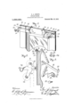
- Figure 1 is a perspective view of the up per portion of a window frame having the improved bracket applied thereto, the curtains and shades being removed therefrom
- Fig. 2 is a central vertical section through the upper portion of the window frame disclosing one of the brackets as applied thereto, the curtains and shades being disclosed in dotted lines inposition
- Fig. 3 is a perspective view of one of the bracket securing means, the parts thereof being'shown detached.
- each of the corner blocks 11 supports a strip 12 which is provided at its outer end with an arm 13 extended inwardly and engaged against the outer edge of the block 11, the arm 13 being retained in such.
- the strip 12 extends inwardly of the frame 10 toward the block 11 and is provided with a series of apertures 15 through which is engaged a locking screw 16.
- a locking bar 17 Connected to the inner end of the strip 12 is a locking bar 17 which is provided with a biting tooth 18 at its lower extremity for engagement against the under side of the framelO at the upper portion thereof adjacent the block 11.
- the bar 17 is provided with a series of apertures corresponding with the apertures 15, and is secured to the strip 12 through the medium of the locking screw 16 which adjusts the relation between the two members.
- a clamping bar 19 is provided which is engaged with the locking screw 16 by the provision of a plurality of apertures formed through the clamping bar 19 at the inner end of the same, the bar 19 having a rounded and threaded portion 20 formed at its outer extremity for the reception of a nut 21 to secure a clamp 22 upon the bar 19.
- the clamp 22 is formed of a portion of sheet metal so stamped as to provide the aperture 23 formed through the inner'end of the same through which the roundedv portion 20 is loosely engaged, the clamp 22 having an in t-egrally formed tooth 24 disposed at its opposite end by the tapering of the portion of metal at the said opposite end.
- the tooth 24 is bent at right angles to the bodyportion of the clamp 22 and is adapted to engage in the upper edge of the frame 10 to lock the clamping bar 19 rigidly with respect to the strip 12.
- the bar 19 is formed of a strip of metal so stamped as to be of elongated formation and provided with a rounded portion which is formed integrally therewith as is disclosed'in the accompanying drawings.
- the bar 17 is also formed 'of a strip of metal which is stamped to form the biting tooth 18 at one extremity and the apertures at the opposite extremity when the member is bent into the form disclosed to dispose the biting tooth 18 inwardly and to extend the same upwardly "to form a hook.
- Thestrip 12 is formed of a flat strip of metal which is apertured as at 15 and formed into hooked shape at its opposite extremity to provide the arm 13 and tooth 14.
- the means employed for retaining the curtains and shades upon the window frame 10 comprises brackets engaging upon each of the strips 12 and which are formed from a sheet of metal so stamped as to provide a sleeve member 25 having inturned flanges 26 for engagement about the edges of the strip 12 to retain the sleeve member 25 upon the strip and to permit of the longitudinal adjustment of the sleeve upon the strip.
- a set screw 27 is disposed in threaded engagement through the outer portion of the sleeve 25 and is engaged at its inner end against the strip 12 in order to bind the flanges 26 against the inner face of the strip 12 and lock the improved bracket in adjusted position.
- the bracket which is formed of a sheet of metal is provided with an arm 28 extendlng outwardly from the frame 10 at substantially right angles to the sleeve 25 and mounted in the lower extremities of the lugs 30.
- the lugs 29 and 30 are provided in the usual manner with a rounded aperture at one side of the device and a slot or elongated aperture at the opposite end of the same in order to support the shade rollers and to enable the operation of the springs disposed therein.
- the curtain support 33 which comprises a strip of metal-extended outwardly in a forward plane and being twisted into a horizontal plane as is disclosed in Figs. 1 and 2 upon the outer extremity of which is provided a hook by the circular curving of the strip of metal to receive frictionally the extremity of a curtain rod 34:.
- the strip frictionally retains the curtain rod 34: by the bending inwardly of the same against the face of the strip so as to reduce the passage through the hook to considerably less than the diameter of the curvature of the same.
- the outer extremity of the strip is disclosed as being rolled although any other formation may be given the same within the scope of the invention as it does not materially alter the operation of the device.
- the strip 12 In securing the curtain and shade roller to a window the strip 12 is engaged against the block 11 to insert the teeth 14 in the outer edge of the block.
- the bars 17 and 19 are now adjusted with respect to the width of the frame 10 to engage the teeth 18 in the under face of the frame and the teeth 24 in the upper edge thereof.
- the lock nut is now rotated about the shank 20 when the clamping member 22 is fed downwardly and inwardly upon the clamping bar 17 to draw the strip 12 inwardly of the frame thereby binding all of the teeth of the device in position.
- the set screw 27 is now released from the strip 12 and the sleeve 25 is longitudinally adjusted in order to obtain the correct adjustment with respect to the lengths of the rollers 31 and 32 employed.
- lugs 29 are positioned inwardly of the lugs 30 and that therefore the shades 31 and 32 will. be supported in different planes relative to the window casing 10, whereupon two shades are positioned against the window, one being a light shade while the opposite one is a dark shade so that the same may be employed in accordance with the light which it is desired to admit into the building.
- a curtain holder including a strip for engagement against the outer face of a window casing, and having an inturned arm with a biting tooth upon its outer end and a series of apertures through its inner end, a pair of diverging bars adjustably secured upon the inner end of the strip and having biting teeth upon their outer ends to engage within the edges of the window casing, a locking screw carried through the inner ends of the bars and the strip, and a bracket arm adjustably mounted for longitudinal movement upon said strip.
- a curtain holder including a strip for engagement against the outer side of a win dow casing, an inturned arm formed upon the outer end of the strip, a tooth carried upon the inner end of the arm to seat within the side of the casing, a pair of diverging clamping bars adjustably carried upon the inner end of the strip, biting teeth formed upon the outer ends of said clamping bars to engage within the edges of the casing, an adjustable arm carried by the strip, and means carried upon one of the clamping bars for binding the same against the edges of the casing.
- a curtain holder including a strip for engagement against the outer face of a window casing, a tooth carried at the outer end of the strip to engage with the edge of the casing, a pair of adjustable clamping bars carried upon the inner end of the strip to bind against the edges of the casing and to draw said strip inwardly to engage the tooth thereof in the side of the casing, and an out wardly-extending arm adjustably carried upon the strip for supporting a curtain.
- a curtain holder including a strip for engagement against the outer face of a window casing, and having an inturned arm with a biting tooth upon its outer end and a series of apertures through its inner end, a pair of diverging bars adjustably' secured upon the inner end of the stripand having biting teeth upon their outer ends to engage within the edges of the window casing, a locking screw carried through the inner ends of the bars and the strip, and a supporting means upon said strip.
- a curtain holder including a strip for engagement against the outer side of a window casing, an inturned arm formed upon the outer end of the strip, a tooth carried upon the inner end of the arm to seat within the side of the casing, a pair of diverging clamping bars adjustably carried upon the inner end of the strip, biting teeth formed upon the outer ends of said clamping bars to engage within the edges of the casing, and a supporting means upon said strip.
- a curtain holder including a strip for engagement against the outer face of a window casing, a tooth carried at the outer end of the strip to engage with the edge of the casing, a pair of adjustable clamping bars carried upon the inner end of the strip tobind against the edges of the casing and to draw said strip inwardly to engage the tooth thereof in the side of the casing, and a supporting means upon said strip.
- a device of the class described comprising a strip adapted for engagement with the outer face of a window casing, apair of ad justable clamping bars carried by the inner end of the strip, one of said bars provided with an inwardly-extending tooth adapted to engage the window casing, the outer end of the other of said bars being screwthreaded, a clamping member provided with a perforation for loosely receiving said threaded bar end, and a perforated nut upon said threaded end adapted for retaining and adjusting said last-mentioned bar with respect to the clamping member.
- a device of the class described comprising a plurality of relatively adjustable strip members, teeth carried by each of said members and adapted for engaging a window casing, an adjustable combined curtain and shade roller support mounted upon one of said members, said strip members each provided at their inner ends with a plurality of perforations adapted for relative alinement, the perforations of one of said members being internally screw-threaded, and a locking screw positioned through openings in each of said members and engaging within said screw-threaded opening.
- a device of the class described comprising a combined curtain and shade roller support, flanges positioned upon the base of said support, a strip engageable against the outer face of a window casing, and said flanges mounted thereon, a set screw positioned through said support and engaging said strip, diagonally opposite extending clamping bars adjustably carried by the inner end of the strip, one of said bars having an integral projecting engaging tooth upon the outer end thereof and the other of said bars having a separable engaging tooth adjustably disposed upon its outer end.
Landscapes
- Curtains And Furnishings For Windows Or Doors (AREA)
Description
G. A. BENOIT.
CURTAIN HOLDER.
Patented Mar. 18. 1 913.
GEORGE A. BENOI'I, OF CHICOPEE FALLS, MASSACHUSETTS.
CURTAIN-HOLDER.
Specification of Letters Patent.
Patented Mar. 18, 1913.
Application filed January 30, 1911. Serial No. 605,538.
To all whom it may concern Be it known that I, GEORGE A. BENOIT, a' citizen of the United States, residing at Chicopee Falls, in the county of Hampden and State ofMassachusetts, have invented certain new and useful Improvements in Curtain-Holders, of which the following is a specification. I a v This invention relates to curtain holders and has particular reference to a device of this character which is applicable to window frames, or like frames upon which the curtain and shades are to be hung and which are adaptable for any size shade.
An object of this invention is to form a combined holder which is capable of supporting not only the curtains but also a pair of shade rollers, the shades of which may be I formed of light and dark material respec-' tively in order to produce the light desired within the room. v
The invention has for another object the provision of a curtain holder and shade bracket combined which is formed in such a manner that it eomprisesbut few operative parts and that the said parts are so shaped as to perform several functions. v
For a full understanding of the invention and the merits thereof, reference is to be had to the following description and accompanying drawings, in which:
Figure 1 is a perspective view of the up per portion of a window frame having the improved bracket applied thereto, the curtains and shades being removed therefrom Fig. 2 is a central vertical section through the upper portion of the window frame disclosing one of the brackets as applied thereto, the curtains and shades being disclosed in dotted lines inposition; and'Fig. 3 is a perspective view of one of the bracket securing means, the parts thereof being'shown detached.
Corresponding and like part-s are referred to in the following description, and indicated in all the views of the accompanying drawings by the same reference characters.
Referring to the drawingsflthe numeral 10 designates a window casing which is provided in the usual manner with corner blocks 11. Each of the corner blocks 11 supports a strip 12 which is provided at its outer end with an arm 13 extended inwardly and engaged against the outer edge of the block 11, the arm 13 being retained in such.
position by the provision of a tooth 14 which bites into the surface of the block 11. The strip 12 extends inwardly of the frame 10 toward the block 11 and is provided with a series of apertures 15 through which is engaged a locking screw 16.
Connected to the inner end of the strip 12 is a locking bar 17 which is provided with a biting tooth 18 at its lower extremity for engagement against the under side of the framelO at the upper portion thereof adjacent the block 11. The bar 17 is provided with a series of apertures corresponding with the apertures 15, and is secured to the strip 12 through the medium of the locking screw 16 which adjusts the relation between the two members. A clamping bar 19 is provided which is engaged with the locking screw 16 by the provision of a plurality of apertures formed through the clamping bar 19 at the inner end of the same, the bar 19 having a rounded and threaded portion 20 formed at its outer extremity for the reception of a nut 21 to secure a clamp 22 upon the bar 19. The clamp 22 is formed of a portion of sheet metal so stamped as to provide the aperture 23 formed through the inner'end of the same through which the roundedv portion 20 is loosely engaged, the clamp 22 having an in t-egrally formed tooth 24 disposed at its opposite end by the tapering of the portion of metal at the said opposite end. The tooth 24 is bent at right angles to the bodyportion of the clamp 22 and is adapted to engage in the upper edge of the frame 10 to lock the clamping bar 19 rigidly with respect to the strip 12.
The bar 19 is formed of a strip of metal so stamped as to be of elongated formation and provided with a rounded portion which is formed integrally therewith as is disclosed'in the accompanying drawings. The bar 17 is also formed 'of a strip of metal which is stamped to form the biting tooth 18 at one extremity and the apertures at the opposite extremity when the member is bent into the form disclosed to dispose the biting tooth 18 inwardly and to extend the same upwardly "to form a hook.- Thestrip 12 is formed of a flat strip of metal which is apertured as at 15 and formed into hooked shape at its opposite extremity to provide the arm 13 and tooth 14.
The means employed for retaining the curtains and shades upon the window frame 10 comprises brackets engaging upon each of the strips 12 and which are formed from a sheet of metal so stamped as to provide a sleeve member 25 having inturned flanges 26 for engagement about the edges of the strip 12 to retain the sleeve member 25 upon the strip and to permit of the longitudinal adjustment of the sleeve upon the strip. A set screw 27 is disposed in threaded engagement through the outer portion of the sleeve 25 and is engaged at its inner end against the strip 12 in order to bind the flanges 26 against the inner face of the strip 12 and lock the improved bracket in adjusted position.
The bracket, which is formed of a sheet of metal is provided with an arm 28 extendlng outwardly from the frame 10 at substantially right angles to the sleeve 25 and mounted in the lower extremities of the lugs 30. The lugs 29 and 30 are provided in the usual manner with a rounded aperture at one side of the device and a slot or elongated aperture at the opposite end of the same in order to support the shade rollers and to enable the operation of the springs disposed therein.
Outwardly extended from the arm 28 is the curtain support 33 which comprises a strip of metal-extended outwardly in a forward plane and being twisted into a horizontal plane as is disclosed in Figs. 1 and 2 upon the outer extremity of which is provided a hook by the circular curving of the strip of metal to receive frictionally the extremity of a curtain rod 34:. The strip frictionally retains the curtain rod 34: by the bending inwardly of the same against the face of the strip so as to reduce the passage through the hook to considerably less than the diameter of the curvature of the same. The outer extremity of the strip is disclosed as being rolled although any other formation may be given the same within the scope of the invention as it does not materially alter the operation of the device.
In securing the curtain and shade roller to a window the strip 12 is engaged against the block 11 to insert the teeth 14 in the outer edge of the block. The bars 17 and 19 are now adjusted with respect to the width of the frame 10 to engage the teeth 18 in the under face of the frame and the teeth 24 in the upper edge thereof. The lock nut is now rotated about the shank 20 when the clamping member 22 is fed downwardly and inwardly upon the clamping bar 17 to draw the strip 12 inwardly of the frame thereby binding all of the teeth of the device in position. The set screw 27 is now released from the strip 12 and the sleeve 25 is longitudinally adjusted in order to obtain the correct adjustment with respect to the lengths of the rollers 31 and 32 employed.
It will be noted from Fig. 2 that the lugs 29 are positioned inwardly of the lugs 30 and that therefore the shades 31 and 32 will. be supported in different planes relative to the window casing 10, whereupon two shades are positioned against the window, one being a light shade while the opposite one is a dark shade so that the same may be employed in accordance with the light which it is desired to admit into the building.
Having thus described the invention, what is claimed as new is:
1. A curtain holder including a strip for engagement against the outer face of a window casing, and having an inturned arm with a biting tooth upon its outer end and a series of apertures through its inner end, a pair of diverging bars adjustably secured upon the inner end of the strip and having biting teeth upon their outer ends to engage within the edges of the window casing, a locking screw carried through the inner ends of the bars and the strip, and a bracket arm adjustably mounted for longitudinal movement upon said strip.
2. A curtain holder including a strip for engagement against the outer side of a win dow casing, an inturned arm formed upon the outer end of the strip, a tooth carried upon the inner end of the arm to seat within the side of the casing, a pair of diverging clamping bars adjustably carried upon the inner end of the strip, biting teeth formed upon the outer ends of said clamping bars to engage within the edges of the casing, an adjustable arm carried by the strip, and means carried upon one of the clamping bars for binding the same against the edges of the casing.
3. A curtain holder including a strip for engagement against the outer face of a window casing, a tooth carried at the outer end of the strip to engage with the edge of the casing, a pair of adjustable clamping bars carried upon the inner end of the strip to bind against the edges of the casing and to draw said strip inwardly to engage the tooth thereof in the side of the casing, and an out wardly-extending arm adjustably carried upon the strip for supporting a curtain.
4. A curtain holder including a strip for engagement against the outer face of a window casing, and having an inturned arm with a biting tooth upon its outer end and a series of apertures through its inner end, a pair of diverging bars adjustably' secured upon the inner end of the stripand having biting teeth upon their outer ends to engage within the edges of the window casing, a locking screw carried through the inner ends of the bars and the strip, and a supporting means upon said strip.
5. A curtain holder including a strip for engagement against the outer side of a window casing, an inturned arm formed upon the outer end of the strip, a tooth carried upon the inner end of the arm to seat within the side of the casing, a pair of diverging clamping bars adjustably carried upon the inner end of the strip, biting teeth formed upon the outer ends of said clamping bars to engage within the edges of the casing, and a supporting means upon said strip.
6. A curtain holder including a strip for engagement against the outer face of a window casing, a tooth carried at the outer end of the strip to engage with the edge of the casing, a pair of adjustable clamping bars carried upon the inner end of the strip tobind against the edges of the casing and to draw said strip inwardly to engage the tooth thereof in the side of the casing, and a supporting means upon said strip.
7. A device of the class described comprising a strip adapted for engagement with the outer face of a window casing, apair of ad justable clamping bars carried by the inner end of the strip, one of said bars provided with an inwardly-extending tooth adapted to engage the window casing, the outer end of the other of said bars being screwthreaded, a clamping member provided with a perforation for loosely receiving said threaded bar end, and a perforated nut upon said threaded end adapted for retaining and adjusting said last-mentioned bar with respect to the clamping member.
8. A device of the class described comprising a plurality of relatively adjustable strip members, teeth carried by each of said members and adapted for engaging a window casing, an adjustable combined curtain and shade roller support mounted upon one of said members, said strip members each provided at their inner ends with a plurality of perforations adapted for relative alinement, the perforations of one of said members being internally screw-threaded, and a locking screw positioned through openings in each of said members and engaging within said screw-threaded opening. 9. A device of the class described comprising a combined curtain and shade roller support, flanges positioned upon the base of said support, a strip engageable against the outer face of a window casing, and said flanges mounted thereon, a set screw positioned through said support and engaging said strip, diagonally opposite extending clamping bars adjustably carried by the inner end of the strip, one of said bars having an integral projecting engaging tooth upon the outer end thereof and the other of said bars having a separable engaging tooth adjustably disposed upon its outer end.
In testimony whereof I aflix my signature in presence of two witnesses.
GEORGE A. BENOIT.
Copies of this patent may be obtained for five cents each, by addressing the Commissioner of 2mm, Washington, D. O.
Priority Applications (1)
| Application Number | Priority Date | Filing Date | Title |
|---|---|---|---|
| US60553811A US1056621A (en) | 1911-01-30 | 1911-01-30 | Curtain-holder. |
Applications Claiming Priority (1)
| Application Number | Priority Date | Filing Date | Title |
|---|---|---|---|
| US60553811A US1056621A (en) | 1911-01-30 | 1911-01-30 | Curtain-holder. |
Publications (1)
| Publication Number | Publication Date |
|---|---|
| US1056621A true US1056621A (en) | 1913-03-18 |
Family
ID=3124875
Family Applications (1)
| Application Number | Title | Priority Date | Filing Date |
|---|---|---|---|
| US60553811A Expired - Lifetime US1056621A (en) | 1911-01-30 | 1911-01-30 | Curtain-holder. |
Country Status (1)
| Country | Link |
|---|---|
| US (1) | US1056621A (en) |
Cited By (1)
| Publication number | Priority date | Publication date | Assignee | Title |
|---|---|---|---|---|
| US11812882B2 (en) * | 2020-07-06 | 2023-11-14 | House of Atlas, LLC | Support bracket |
-
1911
- 1911-01-30 US US60553811A patent/US1056621A/en not_active Expired - Lifetime
Cited By (1)
| Publication number | Priority date | Publication date | Assignee | Title |
|---|---|---|---|---|
| US11812882B2 (en) * | 2020-07-06 | 2023-11-14 | House of Atlas, LLC | Support bracket |
Similar Documents
| Publication | Publication Date | Title |
|---|---|---|
| US1119695A (en) | Window-fixture. | |
| US1095551A (en) | Combination shade and curtain bracket. | |
| US624482A (en) | Window-fixture | |
| US967317A (en) | Curtain-holder. | |
| US1071642A (en) | Curtain-fixture. | |
| US785560A (en) | Curtain-hanger. | |
| US690437A (en) | Curtain-fixture. | |
| US902744A (en) | Curtain and shade holder. | |
| US796238A (en) | Shade-fixture. | |
| US1120902A (en) | Adjustable bracket for curtain-fixtures. | |
| US749088A (en) | Shade-bracket | |
| US1302292A (en) | Shade and curtain holder. | |
| US1103982A (en) | Window shade and curtain fixture. | |
| US704205A (en) | Curtain-fixture. | |
| US787751A (en) | Window-curtain fixture. | |
| US795101A (en) | Bracket. | |
| US723583A (en) | Adjustable shade-roller holder. | |
| US812262A (en) | Window-shade bracket. | |
| US723284A (en) | Curtain-fixture. | |
| US752397A (en) | Curtain-roll support | |
| US951260A (en) | Adjustable curtain-fixture. | |
| US804552A (en) | Curtain-fixture. | |
| US1615868A (en) | Combined shade and curtain holder | |
| US825306A (en) | Shade and curtain fixture. | |
| US614844A (en) | dallin |