US10520719B2 - Image acquisition device - Google Patents
Image acquisition device Download PDFInfo
- Publication number
- US10520719B2 US10520719B2 US15/861,602 US201815861602A US10520719B2 US 10520719 B2 US10520719 B2 US 10520719B2 US 201815861602 A US201815861602 A US 201815861602A US 10520719 B2 US10520719 B2 US 10520719B2
- Authority
- US
- United States
- Prior art keywords
- lens group
- positive lens
- image acquisition
- positive
- acquisition device
- Prior art date
- Legal status (The legal status is an assumption and is not a legal conclusion. Google has not performed a legal analysis and makes no representation as to the accuracy of the status listed.)
- Active, expires
Links
Images


Classifications
-
- G—PHYSICS
- G02—OPTICS
- G02B—OPTICAL ELEMENTS, SYSTEMS OR APPARATUS
- G02B23/00—Telescopes, e.g. binoculars; Periscopes; Instruments for viewing the inside of hollow bodies; Viewfinders; Optical aiming or sighting devices
- G02B23/24—Instruments or systems for viewing the inside of hollow bodies, e.g. fibrescopes
- G02B23/2407—Optical details
- G02B23/2423—Optical details of the distal end
- G02B23/243—Objectives for endoscopes
-
- A—HUMAN NECESSITIES
- A61—MEDICAL OR VETERINARY SCIENCE; HYGIENE
- A61B—DIAGNOSIS; SURGERY; IDENTIFICATION
- A61B1/00—Instruments for performing medical examinations of the interior of cavities or tubes of the body by visual or photographical inspection, e.g. endoscopes; Illuminating arrangements therefor
- A61B1/00064—Constructional details of the endoscope body
- A61B1/00071—Insertion part of the endoscope body
- A61B1/0008—Insertion part of the endoscope body characterised by distal tip features
- A61B1/00096—Optical elements
-
- A—HUMAN NECESSITIES
- A61—MEDICAL OR VETERINARY SCIENCE; HYGIENE
- A61B—DIAGNOSIS; SURGERY; IDENTIFICATION
- A61B1/00—Instruments for performing medical examinations of the interior of cavities or tubes of the body by visual or photographical inspection, e.g. endoscopes; Illuminating arrangements therefor
- A61B1/00163—Optical arrangements
- A61B1/00193—Optical arrangements adapted for stereoscopic vision
-
- G—PHYSICS
- G02—OPTICS
- G02B—OPTICAL ELEMENTS, SYSTEMS OR APPARATUS
- G02B23/00—Telescopes, e.g. binoculars; Periscopes; Instruments for viewing the inside of hollow bodies; Viewfinders; Optical aiming or sighting devices
- G02B23/24—Instruments or systems for viewing the inside of hollow bodies, e.g. fibrescopes
- G02B23/2407—Optical details
- G02B23/2415—Stereoscopic endoscopes
-
- G—PHYSICS
- G02—OPTICS
- G02B—OPTICAL ELEMENTS, SYSTEMS OR APPARATUS
- G02B6/00—Light guides; Structural details of arrangements comprising light guides and other optical elements, e.g. couplings
- G02B6/02—Optical fibres with cladding with or without a coating
- G02B6/036—Optical fibres with cladding with or without a coating core or cladding comprising multiple layers
- G02B6/03616—Optical fibres characterised both by the number of different refractive index layers around the central core segment, i.e. around the innermost high index core layer, and their relative refractive index difference
- G02B6/03638—Optical fibres characterised both by the number of different refractive index layers around the central core segment, i.e. around the innermost high index core layer, and their relative refractive index difference having 3 layers only
- G02B6/03644—Optical fibres characterised both by the number of different refractive index layers around the central core segment, i.e. around the innermost high index core layer, and their relative refractive index difference having 3 layers only arranged - + -
-
- H—ELECTRICITY
- H04—ELECTRIC COMMUNICATION TECHNIQUE
- H04N—PICTORIAL COMMUNICATION, e.g. TELEVISION
- H04N1/00—Scanning, transmission or reproduction of documents or the like, e.g. facsimile transmission; Details thereof
- H04N1/00127—Connection or combination of a still picture apparatus with another apparatus, e.g. for storage, processing or transmission of still picture signals or of information associated with a still picture
- H04N1/00249—Connection or combination of a still picture apparatus with another apparatus, e.g. for storage, processing or transmission of still picture signals or of information associated with a still picture with a photographic apparatus, e.g. a photographic printer or a projector
Definitions
- the present invention relates to an image acquisition device.
- one lens group is moved in the optical-axis direction in order to adjust the focal position on an object surface.
- the present invention provides an image acquisition device including: an imaging optical system that forms two images having parallax; and an image acquisition element that is disposed at an image side of the imaging optical system and that acquires the parallax images, wherein the imaging optical system is provided with a first negative lens group that has a negative refractive power, which are arranged in this order from an object side to an image side; a first positive lens group that has a positive refractive power, and a second positive lens group that has a positive refractive power; the first negative lens group is provided with two negative lens groups that are disposed side by side in a parallax direction corresponding to the parallax images and that have central axes respectively; the first positive lens group is a common lens group that has a single central axis and which light rays emitted from the respective negative lens groups in the first negative lens group to pass through; the second positive lens group is provided with two positive lens groups that are disposed side by side in the parallax direction corresponding to the paralla
- FIG. 1 is a view showing ray tracing of the principal ray when a moving lens group in an image acquisition device according to a first embodiment of the present invention is located at a far-point position.
- FIG. 2 is a view showing ray tracing of the principal ray when the moving lens in the image acquisition device shown in FIG. 1 is located at a near-point position.
- FIG. 3 is a view showing a lens array of an imaging optical system according to Example 1 of the image acquisition device shown in FIG. 1 .
- FIG. 4 is a view showing lateral aberrations of (a) a light ray L 7 , (b) a light ray L 6 , (c) a light ray L 5 , (d) a light ray L 4 , (e) a light ray L 3 , (f) a light ray L 2 , and (g) a light ray L 1 in the Y-direction when the moving lens group in the imaging optical system shown in FIG. 3 is located at the far-point position shown in FIG. 1 .
- FIG. 5 is a view showing lateral aberrations of (a) the light ray L 7 , (b) the light ray L 6 , (c) the light ray L 5 , (d) the light ray L 4 , (e) the light ray L 3 , (f) the light ray L 2 , and (g) the light ray L 1 in the X-direction when the moving lens group in the imaging optical system shown in FIG. 3 is located at the far-point position shown in FIG. 1 .
- FIG. 6 is a view showing lateral aberrations of (a) the light ray L 7 , (b) the light ray L 6 , (c) the light ray L 5 , (d) the light ray L 4 , (e) the light ray L 3 , (f) the light ray L 2 , and (g) the light ray L 1 in the Y-direction when the moving lens group in the imaging optical system shown in FIG. 3 is located at the near-point position shown in FIG. 2 .
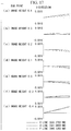
- FIG. 7 is a view showing lateral aberrations of (a) the light ray L 7 , (b) the light ray L 6 , (c) the light ray L 5 , (d) the light ray L 4 , (e) the light ray L 3 , (f) the light ray L 2 , and (g) the light ray L 1 in the X-direction when the moving lens group in the imaging optical system shown in FIG. 3 is located at the near-point position shown in FIG. 2 .
- FIG. 8 is a view showing a lens array of an imaging optical system according to Example 2 of the image acquisition device shown in FIG. 1 .
- FIG. 9 is a view showing lateral aberrations of (a) the light ray L 7 , (b) the light ray L 6 , (c) the light ray L 5 , (d) the light ray L 4 , (e) the light ray L 3 , (f) the light ray L 2 , and (g) the light ray L 1 in the Y-direction when the moving lens group in the imaging optical system shown in FIG. 8 is located at the far-point position.
- FIG. 10 is a view showing lateral aberrations of (a) the light ray L 7 , (b) the light ray L 6 , (c) the light ray L 5 , (d) the light ray L 4 , (e) the light ray L 3 , (f) the light ray L 2 , and (g) the light ray L 1 in the X-direction when the moving lens group in the imaging optical system shown in FIG. 8 is located at the far-point position.
- FIG. 11 is a view showing lateral aberrations of (a) the light ray L 7 , (b) the light ray L 6 , (c) the light ray L 5 , (d) the light ray L 4 , (e) the light ray L 3 , (f) the light ray L 2 , and (g) the light ray L 1 in the Y-direction when the moving lens group in the imaging optical system shown in FIG. 8 is located at the near-point position.
- FIG. 12 is a view showing lateral aberrations of (a) the light ray L 7 , (b) the light ray L 6 , (c) the light ray L 5 , (d) the light ray L 4 , (e) the light ray L 3 , (f) the light ray L 2 , and (g) the light ray L 1 in the X-direction when the moving lens group in the imaging optical system shown in FIG. 8 is located at the near-point position.
- FIG. 13 is a view showing ray tracing of the principal ray when a moving lens group in an image acquisition device according to a second embodiment of the present invention is located at the far-point position.
- FIG. 14 is a view showing ray tracing of the principal ray when the moving lens in the image acquisition device shown in FIG. 13 is located at the near-point position.
- FIG. 15 is a view showing a lens array of an imaging optical system according to Example 3 of the image acquisition device shown in FIG. 13 .
- FIG. 16 is a view showing lateral aberrations of (a) the light ray L 7 , (b) the light ray L 6 , (c) the light ray L 5 , (d) the light ray L 4 , (e) the light ray L 3 , (f) the light ray L 2 , and (g) the light ray L 1 in the Y-direction when the moving lens group in the imaging optical system shown in FIG. 15 is located at the far-point position shown in FIG. 13 .
- FIG. 17 is a view showing lateral aberrations of (a) the light ray L 7 , (b) the light ray L 6 , (c) the light ray L 5 , (d) the light ray L 4 , (e) the light ray L 3 , (f) the light ray L 2 , and (g) the light ray L 1 in the X-direction when the moving lens group in the imaging optical system shown in FIG. 15 is located at the far-point position shown in FIG. 13 .
- FIG. 18 is a view showing lateral aberrations of (a) the light ray L 7 , (b) the light ray L 6 , (c) the light ray L 5 , (d) the light ray L 4 , (e) the light ray L 3 , (f) the light ray L 2 , and (g) the light ray L 1 in the Y-direction when the moving lens group in the imaging optical system shown in FIG. 15 is located at the near-point position shown in FIG. 14 .
- FIG. 19 is a view showing lateral aberrations of (a) the light ray L 7 , (b) the light ray L 6 , (c) the light ray L 5 , (d) the light ray L 4 , (e) the light ray L 3 , (f) the light ray L 2 , and (g) the light ray L 1 in the X-direction when the moving lens group in the imaging optical system shown in FIG. 15 is located at the near-point position shown in FIG. 14 .
- FIG. 20 is a view showing ray tracing of the principal ray when a moving lens group in an image acquisition device according to a third embodiment of the present invention is located at the far-point position.
- FIG. 21 is a view showing ray tracing of the principal ray when the moving lens in the image acquisition device shown in FIG. 20 is located at the near-point position.
- FIG. 22 is a view showing a lens array of an imaging optical system according to Example 4 of the image acquisition device shown in FIG. 20 .
- FIG. 23 is a view showing lateral aberrations of (a) the light ray L 7 , (b) the light ray L 6 , (c) the light ray L 5 , (d) the light ray L 4 , (e) the light ray L 3 , (f) the light ray L 2 , and (g) the light ray L 1 in the Y-direction when the moving lens group in the imaging optical system shown in FIG. 22 is located at the far-point position shown in FIG. 20 .
- FIG. 24 is a view showing lateral aberrations of (a) the light ray L 7 , (b) the light ray L 6 , (c) the light ray L 5 , (d) the light ray L 4 , (e) the light ray L 3 , (f) the light ray L 2 , and (g) the light ray L 1 in the X-direction when the moving lens group in the imaging optical system shown in FIG. 22 is located at the far-point position shown in FIG. 20 .
- FIG. 25 is a view showing lateral aberrations of (a) the light ray L 7 , (b) the light ray L 6 , (c) the light ray L 5 , (d) the light ray L 4 , (e) the light ray L 3 , (f) the light ray L 2 , and (g) the light ray L 1 in the Y-direction when the moving lens group in the imaging optical system shown in FIG. 22 is located at the near-point position shown in FIG. 21 .
- FIG. 26 is a view showing lateral aberrations of (a) the light ray L 7 , (b) the light ray L 6 , (c) the light ray L 5 , (d) the light ray L 4 , (e) the light ray L 3 , (f) the light ray L 2 , and (g) the light ray L 1 in the X-direction when the moving lens group in the imaging optical system shown in FIG. 22 is located at the near-point position shown in FIG. 21 .
- FIG. 27 includes (a) an overall view of a rigid endoscope to which the image acquisition device according to each of the embodiments is applied and (b) a perspective view showing a distal end portion thereof.
- FIG. 28 is an overall view of a flexible electronic endoscope to which the image acquisition device according to each of the embodiments is applied.
- FIG. 29 includes (a) a perspective view of a front portion of a vehicle to which the image acquisition device according to each of the embodiments is applied and (b) a side view thereof.
- the image acquisition device 1 of this embodiment is, for example, an image acquisition device that is provided at the distal end of an insertion portion of an endoscope and, as shown in FIGS. 1 and 2 , is provided with an imaging optical system 2 and an image acquisition element 3 .
- the imaging optical system 2 is provided with, in order from an object side toward an image side, a first negative lens group 4 having a negative refractive power, a first positive lens group 5 having a positive refractive power, and a second positive lens group 6 having a positive refractive power, and forms two parallax images.
- the first negative lens group 4 is provided with two negative lens groups 7 and 8 that are disposed side by side in the parallax direction corresponding to the two parallax images and that have central axes A and B, respectively.
- the respective negative lens groups 7 and 8 of the first negative lens group 4 have, in order from the object side, a plano-concave lens 9 that has concave surfaces on the image side thereof, a combined lens 10 that is made up of a biconcave lens and a biconvex lens, and one meniscus lens 11 that has concave surfaces on the object side thereof. Furthermore, as the combined lens 10 , lenses of which only two surfaces, i.e., an object-side surface and an image-side surface, are in contact with air on the central axes A and B are lens components.
- the first positive lens group 5 has a single central axis (common central axis) S, is a common lens group that causes light rays emitted from the respective negative lens groups 7 and 8 in the first negative lens group 4 to pass therethrough, and is formed of a combined lens 12 made up of a meniscus lens having a convex surface on the object side thereof and a biconvex lens.
- the first positive lens group 5 forms a moving lens group that is provided movably along the common central axis S.
- the second positive lens group 6 is provided with two positive lens groups 13 and 14 that are disposed side by side in the parallax direction corresponding to the parallax images and that have central axes X and Y, respectively.
- the respective positive lens groups 13 and 14 in the second positive lens group 6 have, in order from the object side, a combined lens 15 that is made up of a meniscus lens having a convex surface on the object side thereof and a biconvex lens, and a biconvex lens 16 .
- An aperture stop (stop) 17 that has openings corresponding to the parallax images is provided between the first positive lens group 5 and the second positive lens group 6 .
- Light rays from an object are collected, in a state in which they are separated into two according to the parallax, by the two negative lens groups 7 and 8 in the first negative lens group 4 , pass through the first positive lens group 5 , which is the common lens group, and, when entering the second positive lens group 6 , are again separated into two according to the parallax, thereby being formed into two parallax images by means of the respective positive lens groups 13 and 14 , which constitute the second positive lens group 6 .
- the image acquisition element 3 is formed of a CCD, a CMOS, or the like in which an imaging surface 18 is disposed at imaging positions of the parallax images formed by the second positive lens group 6 .
- the image acquisition device 1 of this embodiment satisfies the following conditions (1) to (4).
- fm >( Dk ⁇ D )/( ih ⁇ 0.2) (1) ⁇ 1.6 ⁇ fGN 1/ fGP 2 ⁇ 0.6 (2) ⁇ 1.5 ⁇ Dk/fGN 1 ⁇ 0 (3) 1> Dk/fGP 2>0 (4)
- fm >( Dk ⁇ D )/( ih ⁇ 0.2) (1) ⁇ 1.6 ⁇ fGN 1/ fGP 2 ⁇ 0.6 (2) ⁇ 1.5 ⁇ Dk/fGN 1 ⁇ 0 (3) 1> Dk/fGP 2>0 (4)
- fm indicates the absolute value of the focal length of the moving lens group 5 .
- ⁇ D indicates the maximum amount of movement of the moving lens group 5 .
- ih indicates the image height of a parallax image
- Dk indicates the distance between the central axes X and Y of the two positive lens groups 13 and 14 , which constitute the second positive lens group 6 ,
- fGN 1 indicates the focal length of the first negative lens group 4 .
- fGP 2 indicates the focal length of the second positive lens group 6 .
- condition (1) is derived, provided that the amount of change ⁇ Y in the image height is smaller than 10% of the image height ih, specifically, ⁇ Y ⁇ ih ⁇ 0.1.
- the image acquisition device 1 of this embodiment when light rays from an object enter the image acquisition device 1 , two images having parallax are formed in the imaging optical system 2 , and the two parallax images are acquired by the image acquisition element 3 .
- the light rays from the object are separated into two according to parallax and are collected by the two negative lens groups 7 and 8 , which constitute the first negative lens group 4 , thus making it possible to secure a wide angle of view and causing the diameters of light fluxes collected by the first negative lens group 4 to be kept narrow by the first positive lens group 5 , which is provided at the sequent stage.
- the light rays passing through the first positive lens group 5 enter the second positive lens group 6 , which is provided with the two positive lens groups 13 and 14 disposed side by side in the parallax direction, thereby being separated again into two parallax images, and the two parallax images are acquired by the image acquisition element 3 .
- the single combined lens 12 which forms the first positive lens group 5 , is moved along the common central axis S, thus making it possible to adjust the focus position with a simple movement mechanism. Accordingly, it is possible to achieve a reduction in the diameter and a reduction in the length of the image acquisition device 1 .
- the image acquisition device 1 of this embodiment there is an advantage in that the structure is simplified, thus making it possible to prevent an increase in size and to sufficiently increase the angle of view.
- the first positive lens group 5 which is disposed between the first negative lens group 4 and the second positive lens group 6 and which is the common lens group, is moved along the common central axis S, the second positive lens group 6 , which is close to the image acquisition element 3 , need not be moved.
- the second positive lens group 6 which is close to the image acquisition element 3 , need not be moved.
- the first positive lens group 5 is formed of the combined lens 12 , which is made up of the meniscus lens having a convex surface on the image side thereof and the biconvex lens, it is possible to suppress a fluctuation of chromatic aberration caused by movement thereof.
- the aperture stop 17 may be eccentrically disposed with respect to the each of the central axes X and Y of the two positive lens groups 13 and 14 in the second positive lens group 6 .
- the distance between the centers of the two openings of the aperture stop 17 may be larger than the distance between the central axes X and Y of the two positive lens groups 13 and 14 in the second positive lens group 6 . By doing so, it is possible to reduce crosstalk of the parallax images obtained when the imaging angle of view is increased.
- the distance between the centers of the two openings of the aperture stop 17 may be smaller than the distance between the central axes X and Y of the two positive lens groups 13 and 14 in the second positive lens group 6 . By doing so, the distance between the parallax images is reduced, thus making it possible to reduce the size of the imaging surface 18 of the image acquisition element 3 .
- condition (1) is satisfied, there is an advantage in that it is possible to suppress an aberration caused by a driving error of the moving lens group 5 .
- condition (2) is satisfied, it is possible to reduce a fluctuation in aberration when the moving lens group 5 is moved.
- Example 1 of the image acquisition device 1 of this embodiment will be described below by using FIGS. 3 to 7 and lens data.
- FIG. 3 shows a lens array of the imaging optical system 2 of the image acquisition device 1 of this Example. Furthermore, FIGS. 4 to 7 are aberration diagrams corresponding to respective light rays L 1 to L 7 in the imaging optical system 2 of this Example.
- the maximum angle of view (far point) is 120′
- the image height is 0.4 mm
- the Fno is 4.
- r indicates the radius of curvature (mm)
- d indicates inter-surface distance (mm)
- Nd indicates the refractive index with respect to the d line
- ⁇ indicates the Abbe number.
- OBJ indicates a subject (object).
- the object point, the inter-surface distance 7 , and the inter-surface distance 10 in the above-described lens data show values obtained when the moving lens group 5 is located at a far-point position.
- the eleventh surface denotes the aperture stop 17
- the amounts of eccentricities yde at the eighth surface, the eleventh surface, and the eighteenth surface with respect to the central axis S at the object sides thereof are:
- Example 2 of the image acquisition device 1 of this embodiment will be described below by using FIGS. 8 to 12 and lens data.
- FIG. 8 shows a lens array of the imaging optical system 2 of the image acquisition device 1 of this Example. Furthermore, FIGS. 9 to 12 are aberration diagrams corresponding to respective light rays L 1 to L 7 in the imaging optical system 2 of this Example.
- the maximum angle of view (far point) is 122°
- the image height is 0.4 mm
- the Fno is 3.5.
- the object point, the inter-surface distance 7 , and the inter-surface distance 10 in the above-described lens data show values obtained when the moving lens group 5 is located at the far-point position.
- the eleventh surface denotes the aperture stop 17
- the amounts of eccentricities yde at the eighth surface, the eleventh surface, and the eighteenth surface with respect to the central axis S at the object sides thereof are:
- this embodiment differs from the image acquisition device 1 of the first embodiment in terms of two negative lens groups 23 and 24 in a first negative lens group 22 , and a first positive lens group 25 .
- This embodiment differs from the image acquisition device 1 of the first embodiment in that the two negative lens groups 23 and 24 in the first negative lens group 22 include: a combined lens 26 that is made up of a biconcave lens and a meniscus lens having a concave surface on the image side thereof; and a biconvex lens 27 .
- this embodiment differs from the image acquisition device 1 of the first embodiment in that the first positive lens group 25 is provided with, in order from the object side: a combined lens 28 that is made up of a meniscus lens having a convex surface on the object side thereof and a biconvex lens; and one biconcave lens 29 , and in that the combined lens 28 forms a moving lens group.
- this embodiment differs from the image acquisition device 1 of the first embodiment in that the aperture stop 17 having openings corresponding to respective parallax images is provided between the combined lens 28 and the biconcave lens 29 , which constitute the first positive lens group 25 .
- the first positive lens group 25 is provided with the plurality of lens groups, which are disposed with a space which is variable, and the plurality of lens groups include the combined lens (positive lens group) 28 , which has a positive refractive power, and the biconcave lens (negative lens group) 29 , which has a negative refractive power, there is an advantage in that a shift of the optical axis in the common lens can be suppressed by means of a combination of concavity and convexity.
- the aperture stop 17 which has the openings corresponding to the respective parallax, is provided between the combined lens 28 and the biconcave lens 29 , it is possible to minimize the spreading of the light fluxes at the position of the aperture stop 17 and to suppress the spreading of the light fluxes at the image side and the object side of the aperture stop 17 . Accordingly, it is possible to suppress both the effective diameter of the first negative lens group 22 and the effective diameter of the second positive lens group 6 and to reduce the impact of vignetting. Then, even when the distance between the pupils of the negative lens groups 23 and 24 in the first negative lens group 22 is not increased, it is possible to acquire parallax images with a wide angle of view and to achieve a reduction in size.
- Example 3 of the image acquisition device 20 of this embodiment will be described below by using FIGS. 15 to 19 and lens data.
- FIG. 15 shows a lens array of an imaging optical system 21 of the image acquisition device 20 of this Example. Furthermore, FIGS. 16 to 19 are aberration diagrams corresponding to respective light rays L 1 to L 7 in the imaging optical system 21 of this Example.
- the maximum angle of view (far point) is 140°
- the image height is 0.4 mm
- the Fno is 4.
- the object point, the inter-surface distance 7 , and the inter-surface distance 10 in the above-described lens data show values obtained when the moving lens group 28 is located at the far-point position.
- the eleventh surface denotes the aperture stop 17
- the amounts of eccentricities yde at the eighth surface, the eleventh surface, the twelfth surface, the fourteenth surface, and the twenty-first surface with respect to the central axis S at the object sides thereof are:
- this embodiment differs from the image acquisition device 20 of the second embodiment in terms of a first negative lens group 32 and a first positive lens group 33 .
- This embodiment differs from the image acquisition device 20 of the second embodiment in that two negative lens groups 34 and 35 in the first negative lens group 32 include: a combined lens 36 that is made up of a biconcave lens and a meniscus lens having a concave surface on the image side thereof; and one meniscus lens 37 that has a concave surface directed toward the object side.
- this embodiment differs from the image acquisition device 20 of the second embodiment in that the first positive lens group 33 is provided with, in order from the object side: a combined lens 38 that is made up of two meniscus lenses having concave surfaces directed toward the object side; and one meniscus lens 39 that has a concave surface directed toward the object side.
- Example 4 of the image acquisition device 30 of this embodiment will be described below by using FIGS. 22 to 26 and lens data.
- FIG. 22 shows a lens array of an imaging optical system 31 of the image acquisition device 30 of this Example. Furthermore, FIGS. 23 to 26 are aberration diagrams corresponding to respective light rays L 1 to L 7 in the imaging optical system 31 of this Example.
- the maximum angle of view (far point) is 140°
- the image height is 0.4 mm
- the Fno is 3.5.
- the object point, the inter-surface distance 7 , and the inter-surface distance 10 in the above-described lens data show values obtained when the moving lens group 38 is located at the far-point position.
- the eleventh surface denotes the aperture stop 17
- the amounts of eccentricities yde in the eighth surface, the eleventh surface, the twelfth surface, the fourteenth surface, and the twenty-first surface with respect to the central axis S at the object sides thereof are:
- Table 1 shows values of conditions (1) to (4) in the above-described four Examples.
- FIG. 27 includes views showing an example in which the image acquisition device 1 , 20 , 30 of each of the embodiments is applied to an endoscope.
- FIG. 27( a ) is an overall view showing a rigid endoscope 110
- FIG. 27( b ) shows the image acquisition device 1 , 20 , 30 of each of the embodiments attached to a distal end of the rigid endoscope 110 .
- FIG. 28 is an overall view showing a flexible-electronic-endoscope system.
- the image acquisition device 1 , 20 , 30 of each of the above-described embodiments is attached to a distal end of an insertion portion of a flexible electronic endoscope 113 , and an acquired image is subjected to image processing to correct distortion and is stereoscopically displayed on a display device 114 .
- the image acquisition device 1 , 20 , 30 of each of the embodiments is applied to an endoscope, thereby making it possible to stereoscopically acquire and observe an omnidirectional image and to stereoscopically observe various sites from angles different from the conventional techniques.
- FIG. 29 includes views showing an example in which the image acquisition device 1 , 20 , 30 of each of the embodiments of the present invention is applied to a vehicle 130 .
- the image acquisition device 1 , 20 , 30 is attached to respective portions of the vehicle 130 , and acquired images are subjected to image processing to correct distortion and are stereoscopically displayed on a display device (not shown) in the vehicle at the same time.
- the present invention provides an image acquisition device including: an imaging optical system that forms two images having parallax; and an image acquisition element that is disposed at an image side of the imaging optical system and that acquires the parallax images, wherein the imaging optical system is provided with a first negative lens group that has a negative refractive power, which are arranged in this order from an object side to an image side; a first positive lens group that has a positive refractive power, and a second positive lens group that has a positive refractive power; the first negative lens group is provided with two negative lens groups that are disposed side by side in a parallax direction corresponding to the parallax images and that have central axes respectively; the first positive lens group is a common lens group that has a single central axis and which light rays emitted from the respective negative lens groups in the first negative lens group to pass through; the second positive lens group is provided with two positive lens groups that are disposed side by side in the parallax direction corresponding to the paralla
- the image acquisition device when light rays from an object enter the image acquisition device, two images having parallax are formed in the imaging optical system, and two parallax images are acquired by the image acquisition element. Because light rays from the object are focused by the first negative lens group, a wide angle of view can be secured, and the light fluxes individually focused by the two negative lens groups, which are disposed side by side in the parallax direction, corresponding to the parallax images are maintained at a small light-flux diameter by the first positive lens group, which is formed of a common lens group, located at the sequent stage.
- the light rays that have passed through the first positive lens group again enter the second positive lens group, which is provided with the two positive lens groups disposed side by side in the parallax direction, thereby being respectively formed into two parallax images and acquired by the image acquisition element.
- the first positive lens group which is disposed between the first negative lens group and the second positive lens group and which is the common lens group, is moved along the common central axis; therefore, it is not necessary to move the second positive lens group, which is close to the image acquisition element, thus making it possible to reduce the distance between the central axes of the two positive lens groups in the second positive lens group and to minimize the parallax.
- the second positive lens group is moved, it is possible to reduce the impact of a driving error caused when the first positive lens group is moved along the common central axis and to minimize the incident angles at the image acquisition element, thus making it possible to suppress a reduction in detection sensitivity.
- the moving lens group may be provided with combined lens component including a positive lens that has a positive refractive power and a negative lens that has a negative refractive power.
- the first positive lens group may be provided with a plurality of lens groups that are disposed side by side with a space which is variable.
- the first positive lens group may be provided with a positive lens group that has a positive refractive power and a negative lens group that has a negative refractive power.
- the distance between the positive lens group and the negative lens group in the first positive lens group may vary.
- the positive lens group in the first positive lens group may be a moving lens group; and the negative lens group may be statically disposed on an image side of the positive lens group.
- the moving lens group may satisfy condition (1): fm >( Dk ⁇ D )/( ih ⁇ 0.2) (1) wherein fm indicates an absolute value of a focal length of the moving lens group, ⁇ D indicates a maximum amount of movement of the moving lens group, ih indicates an image height of the parallax image, and Dk indicates a distance between the central axes in the second positive lens group.
- the imaging optical system may be provided with an aperture stop that has openings corresponding to the respective parallax images; and a center of any one of the openings of the aperture stop may be eccentric with respect to the central axis of the corresponding negative lens group in the first negative lens group.
- distance between the centers of the plurality of openings may be larger than distance between the central axes of the corresponding negative lens groups in the first negative lens group.
- distance between the centers of the plurality of openings may be smaller than distance between the central axes of the corresponding negative lens groups in the first negative lens group.
- the imaging optical system may be provided with an aperture stop that has openings corresponding to the respective parallax images; the first positive lens group may have a plurality of lens groups; and the openings may be located in the plurality of lens groups in the first positive lens group.
- the image acquisition device may satisfy condition (2); ⁇ 1.6 ⁇ fGN 1/ fGP 2 ⁇ 0.6 (2) wherein fGN 1 indicates a focal length of the first negative lens group, and fGP 2 indicates a focal length of the second positive lens group.
- the ratio of the focal length of the first negative lens group and the focal length of the second positive lens group is set close to ⁇ 1, and the magnification at the first positive lens group, which is disposed between the first negative lens group and the second positive lens group and which is the common lens group, is set around ⁇ 1, thus making it possible to reduce a fluctuation in aberration when the moving lens group is moved.
- the image acquisition device may satisfy condition (3); ⁇ 1.5 ⁇ Dk/fGN 1 ⁇ 0 (3) wherein fGN 1 indicates a focal length of the first negative lens group, and Dk indicates a distance between the central axes in the second positive lens group.
- the image acquisition device may satisfy condition (4); 1> Dk/fGP 2>0 (4) wherein fGP 2 indicates a focal length of the second positive lens group, and Dk indicates a distance between the central axes in the second positive lens group.
- the aforementioned aspects afford an advantageous effect in that it is possible to suppress an increase in parallax, to reduce the angles of incidence of light rays on an image acquisition element, and to acquire a clear image.
Applications Claiming Priority (1)
| Application Number | Priority Date | Filing Date | Title |
|---|---|---|---|
| PCT/JP2015/073593 WO2017033234A1 (fr) | 2015-08-21 | 2015-08-21 | Dispositif de capture d'images |
Related Parent Applications (1)
| Application Number | Title | Priority Date | Filing Date |
|---|---|---|---|
| PCT/JP2015/073593 Continuation WO2017033234A1 (fr) | 2015-08-21 | 2015-08-21 | Dispositif de capture d'images |
Publications (2)
| Publication Number | Publication Date |
|---|---|
| US20180120554A1 US20180120554A1 (en) | 2018-05-03 |
| US10520719B2 true US10520719B2 (en) | 2019-12-31 |
Family
ID=58100159
Family Applications (1)
| Application Number | Title | Priority Date | Filing Date |
|---|---|---|---|
| US15/861,602 Active 2035-11-15 US10520719B2 (en) | 2015-08-21 | 2018-01-03 | Image acquisition device |
Country Status (3)
| Country | Link |
|---|---|
| US (1) | US10520719B2 (fr) |
| JP (1) | JPWO2017033234A1 (fr) |
| WO (1) | WO2017033234A1 (fr) |
Families Citing this family (5)
| Publication number | Priority date | Publication date | Assignee | Title |
|---|---|---|---|---|
| WO2018189853A1 (fr) | 2017-04-13 | 2018-10-18 | オリンパス株式会社 | Système optique d'endoscope stéréoscopique et endoscope équipé de celui-ci |
| WO2018211595A1 (fr) | 2017-05-16 | 2018-11-22 | オリンパス株式会社 | Système optique destiné à une visualisation stéréoscopique et dispositif d'imagerie équipé d'un tel système |
| WO2019008618A1 (fr) | 2017-07-03 | 2019-01-10 | オリンパス株式会社 | Système optique stéréoscopique et dispositif d'imagerie muni de ce système |
| WO2019064515A1 (fr) | 2017-09-29 | 2019-04-04 | オリンパス株式会社 | Système optique stéréoscopique et dispositif d'imagerie équipé de celui-ci |
| CN117676294A (zh) * | 2022-08-09 | 2024-03-08 | 晋城三赢精密电子有限公司 | 摄像头模组及电子产品 |
Citations (12)
| Publication number | Priority date | Publication date | Assignee | Title |
|---|---|---|---|---|
| JPH07261099A (ja) | 1994-03-17 | 1995-10-13 | Olympus Optical Co Ltd | 立体視内視鏡 |
| JPH07294827A (ja) | 1994-04-20 | 1995-11-10 | Olympus Optical Co Ltd | 内視鏡 |
| JP2001147382A (ja) | 1999-11-19 | 2001-05-29 | Olympus Optical Co Ltd | 内視鏡用対物光学系 |
| US20010004298A1 (en) | 1999-12-10 | 2001-06-21 | Shuichi Kobayashi | Optical system for photographing stereoscopic image, and stereoscopic image photographing apparatus having the optical system |
| US20020082476A1 (en) | 1994-03-17 | 2002-06-27 | Olympus Optical Co. | Stereoendoscope wherein images having passed through plural incident pupils are transmitted by common relay optical systems |
| JP2003005096A (ja) | 2001-06-27 | 2003-01-08 | Olympus Optical Co Ltd | 内視鏡装置 |
| US20030125608A1 (en) | 1999-11-19 | 2003-07-03 | Olympus Optical Co., Ltd. | Endoscope apparatus |
| US20090096865A1 (en) | 2007-10-10 | 2009-04-16 | Mckinley Harry R | Stereoscopic zoom endoscope |
| US20130120646A1 (en) * | 2010-07-26 | 2013-05-16 | Panasonic Corporation | Lens unit |
| JP2014160240A (ja) | 2013-01-23 | 2014-09-04 | Olympus Medical Systems Corp | 光学系、立体撮像装置、及び内視鏡 |
| WO2014147856A1 (fr) | 2013-03-22 | 2014-09-25 | オリンパス株式会社 | Système optique pour une imagerie en trois dimensions, dispositif pour une imagerie en trois dimensions, et endoscope |
| US20150219882A1 (en) * | 2014-01-31 | 2015-08-06 | Canon Kabushiki Kaisha | Zoom lens and imaging apparatus having the same |
-
2015
- 2015-08-21 JP JP2017536077A patent/JPWO2017033234A1/ja active Pending
- 2015-08-21 WO PCT/JP2015/073593 patent/WO2017033234A1/fr active Application Filing
-
2018
- 2018-01-03 US US15/861,602 patent/US10520719B2/en active Active
Patent Citations (18)
| Publication number | Priority date | Publication date | Assignee | Title |
|---|---|---|---|---|
| US20020082476A1 (en) | 1994-03-17 | 2002-06-27 | Olympus Optical Co. | Stereoendoscope wherein images having passed through plural incident pupils are transmitted by common relay optical systems |
| JPH07261099A (ja) | 1994-03-17 | 1995-10-13 | Olympus Optical Co Ltd | 立体視内視鏡 |
| JPH07294827A (ja) | 1994-04-20 | 1995-11-10 | Olympus Optical Co Ltd | 内視鏡 |
| US20030125608A1 (en) | 1999-11-19 | 2003-07-03 | Olympus Optical Co., Ltd. | Endoscope apparatus |
| JP2001147382A (ja) | 1999-11-19 | 2001-05-29 | Olympus Optical Co Ltd | 内視鏡用対物光学系 |
| US20010004298A1 (en) | 1999-12-10 | 2001-06-21 | Shuichi Kobayashi | Optical system for photographing stereoscopic image, and stereoscopic image photographing apparatus having the optical system |
| JP2001166258A (ja) | 1999-12-10 | 2001-06-22 | Canon Inc | 立体画像撮影用光学系及びそれを用いた立体画像撮影装置 |
| US6632172B1 (en) | 2000-11-17 | 2003-10-14 | Olympus Optical Co., Ltd. | Endoscope apparatus |
| JP2003005096A (ja) | 2001-06-27 | 2003-01-08 | Olympus Optical Co Ltd | 内視鏡装置 |
| US20090096865A1 (en) | 2007-10-10 | 2009-04-16 | Mckinley Harry R | Stereoscopic zoom endoscope |
| US20130120646A1 (en) * | 2010-07-26 | 2013-05-16 | Panasonic Corporation | Lens unit |
| JP2014160240A (ja) | 2013-01-23 | 2014-09-04 | Olympus Medical Systems Corp | 光学系、立体撮像装置、及び内視鏡 |
| WO2014147856A1 (fr) | 2013-03-22 | 2014-09-25 | オリンパス株式会社 | Système optique pour une imagerie en trois dimensions, dispositif pour une imagerie en trois dimensions, et endoscope |
| US20160070094A1 (en) | 2013-03-22 | 2016-03-10 | Olympus Corporation | Stereoscopic imaging optical system assembly, stereoscopic imaging apparatus, and endoscope |
| WO2015107733A1 (fr) | 2014-01-15 | 2015-07-23 | オリンパス株式会社 | Système optique, dispositif de lecture d'image stéréoscopique, et endoscope |
| US20160320606A1 (en) | 2014-01-15 | 2016-11-03 | Olympus Corporation | Optical system, stereoscopic imaging device, and endoscope |
| EP3096168A1 (fr) | 2014-01-15 | 2016-11-23 | Olympus Corporation | Système optique, dispositif de lecture d'image stéréoscopique, et endoscope |
| US20150219882A1 (en) * | 2014-01-31 | 2015-08-06 | Canon Kabushiki Kaisha | Zoom lens and imaging apparatus having the same |
Non-Patent Citations (2)
| Title |
|---|
| International Search Report (ISR) dated Nov. 17, 2015 issued in International Application No. PCT/JP2015/073593. |
| Written Opinion dated Nov. 17, 2015 issued in International Application No. PCT/JP2015/073593. |
Also Published As
| Publication number | Publication date |
|---|---|
| WO2017033234A1 (fr) | 2017-03-02 |
| US20180120554A1 (en) | 2018-05-03 |
| JPWO2017033234A1 (ja) | 2018-06-07 |
Similar Documents
| Publication | Publication Date | Title |
|---|---|---|
| US10520719B2 (en) | Image acquisition device | |
| JP6280749B2 (ja) | 光学系、立体撮像装置、及び内視鏡 | |
| US9864185B2 (en) | Three-dimensional-endoscope optical system | |
| US10686973B2 (en) | Image pickup apparatus with two optical systems | |
| US8988516B2 (en) | Imaging device and endoscope | |
| US11478134B2 (en) | Stereoscopic-vision endoscope optical system and endoscope using the same | |
| US10462363B2 (en) | Optical apparatus | |
| US11058287B2 (en) | Optical system for stereoscopic vision and image pickup apparatus using the same | |
| JP6727795B2 (ja) | 撮像装置及びそれを有する撮像システム | |
| US10955656B2 (en) | Image-acquisition apparatus | |
| US11249299B2 (en) | Stereoscopic vision optical system and endoscope using the same | |
| US9297986B2 (en) | Wide angle lens system and electronic apparatus having the same | |
| US20160313543A1 (en) | Optical system and imaging apparatus including the same | |
| JP5629996B2 (ja) | 立体視光学装置および結像光学装置 | |
| WO2019064515A1 (fr) | Système optique stéréoscopique et dispositif d'imagerie équipé de celui-ci | |
| JP7095076B2 (ja) | 立体内視鏡対物光学系及びそれを備えた内視鏡 |
Legal Events
| Date | Code | Title | Description |
|---|---|---|---|
| AS | Assignment |
Owner name: OLYMPUS CORPORATION, JAPAN Free format text: ASSIGNMENT OF ASSIGNORS INTEREST;ASSIGNOR:FUKUSHIMA, IKUTOSHI;REEL/FRAME:044528/0095 Effective date: 20171128 |
|
| FEPP | Fee payment procedure |
Free format text: ENTITY STATUS SET TO UNDISCOUNTED (ORIGINAL EVENT CODE: BIG.); ENTITY STATUS OF PATENT OWNER: LARGE ENTITY |
|
| STPP | Information on status: patent application and granting procedure in general |
Free format text: DOCKETED NEW CASE - READY FOR EXAMINATION |
|
| STPP | Information on status: patent application and granting procedure in general |
Free format text: NON FINAL ACTION MAILED |
|
| STPP | Information on status: patent application and granting procedure in general |
Free format text: RESPONSE TO NON-FINAL OFFICE ACTION ENTERED AND FORWARDED TO EXAMINER |
|
| STPP | Information on status: patent application and granting procedure in general |
Free format text: NOTICE OF ALLOWANCE MAILED -- APPLICATION RECEIVED IN OFFICE OF PUBLICATIONS |
|
| STPP | Information on status: patent application and granting procedure in general |
Free format text: PUBLICATIONS -- ISSUE FEE PAYMENT RECEIVED |
|
| STCF | Information on status: patent grant |
Free format text: PATENTED CASE |
|
| MAFP | Maintenance fee payment |
Free format text: PAYMENT OF MAINTENANCE FEE, 4TH YEAR, LARGE ENTITY (ORIGINAL EVENT CODE: M1551); ENTITY STATUS OF PATENT OWNER: LARGE ENTITY Year of fee payment: 4 |