US10411233B2 - Secondary battery cartridge and battery module comprising same - Google Patents
Secondary battery cartridge and battery module comprising same Download PDFInfo
- Publication number
- US10411233B2 US10411233B2 US15/559,710 US201615559710A US10411233B2 US 10411233 B2 US10411233 B2 US 10411233B2 US 201615559710 A US201615559710 A US 201615559710A US 10411233 B2 US10411233 B2 US 10411233B2
- Authority
- US
- United States
- Prior art keywords
- battery
- secondary battery
- storing box
- case
- cartridge
- Prior art date
- Legal status (The legal status is an assumption and is not a legal conclusion. Google has not performed a legal analysis and makes no representation as to the accuracy of the status listed.)
- Active, expires
Links
Images




Classifications
-
- H01M2/1252—
-
- H—ELECTRICITY
- H01—ELECTRIC ELEMENTS
- H01M—PROCESSES OR MEANS, e.g. BATTERIES, FOR THE DIRECT CONVERSION OF CHEMICAL ENERGY INTO ELECTRICAL ENERGY
- H01M10/00—Secondary cells; Manufacture thereof
- H01M10/42—Methods or arrangements for servicing or maintenance of secondary cells or secondary half-cells
- H01M10/48—Accumulators combined with arrangements for measuring, testing or indicating the condition of cells, e.g. the level or density of the electrolyte
- H01M10/482—Accumulators combined with arrangements for measuring, testing or indicating the condition of cells, e.g. the level or density of the electrolyte for several batteries or cells simultaneously or sequentially
-
- H01M2/043—
-
- H01M2/1077—
-
- H01M2/1094—
-
- H—ELECTRICITY
- H01—ELECTRIC ELEMENTS
- H01M—PROCESSES OR MEANS, e.g. BATTERIES, FOR THE DIRECT CONVERSION OF CHEMICAL ENERGY INTO ELECTRICAL ENERGY
- H01M50/00—Constructional details or processes of manufacture of the non-active parts of electrochemical cells other than fuel cells, e.g. hybrid cells
- H01M50/20—Mountings; Secondary casings or frames; Racks, modules or packs; Suspension devices; Shock absorbers; Transport or carrying devices; Holders
- H01M50/204—Racks, modules or packs for multiple batteries or multiple cells
- H01M50/207—Racks, modules or packs for multiple batteries or multiple cells characterised by their shape
- H01M50/211—Racks, modules or packs for multiple batteries or multiple cells characterised by their shape adapted for pouch cells
-
- H—ELECTRICITY
- H01—ELECTRIC ELEMENTS
- H01M—PROCESSES OR MEANS, e.g. BATTERIES, FOR THE DIRECT CONVERSION OF CHEMICAL ENERGY INTO ELECTRICAL ENERGY
- H01M50/00—Constructional details or processes of manufacture of the non-active parts of electrochemical cells other than fuel cells, e.g. hybrid cells
- H01M50/20—Mountings; Secondary casings or frames; Racks, modules or packs; Suspension devices; Shock absorbers; Transport or carrying devices; Holders
- H01M50/218—Mountings; Secondary casings or frames; Racks, modules or packs; Suspension devices; Shock absorbers; Transport or carrying devices; Holders characterised by the material
- H01M50/22—Mountings; Secondary casings or frames; Racks, modules or packs; Suspension devices; Shock absorbers; Transport or carrying devices; Holders characterised by the material of the casings or racks
- H01M50/222—Inorganic material
- H01M50/224—Metals
-
- H—ELECTRICITY
- H01—ELECTRIC ELEMENTS
- H01M—PROCESSES OR MEANS, e.g. BATTERIES, FOR THE DIRECT CONVERSION OF CHEMICAL ENERGY INTO ELECTRICAL ENERGY
- H01M50/00—Constructional details or processes of manufacture of the non-active parts of electrochemical cells other than fuel cells, e.g. hybrid cells
- H01M50/20—Mountings; Secondary casings or frames; Racks, modules or packs; Suspension devices; Shock absorbers; Transport or carrying devices; Holders
- H01M50/233—Mountings; Secondary casings or frames; Racks, modules or packs; Suspension devices; Shock absorbers; Transport or carrying devices; Holders characterised by physical properties of casings or racks, e.g. dimensions
- H01M50/24—Mountings; Secondary casings or frames; Racks, modules or packs; Suspension devices; Shock absorbers; Transport or carrying devices; Holders characterised by physical properties of casings or racks, e.g. dimensions adapted for protecting batteries from their environment, e.g. from corrosion
-
- H—ELECTRICITY
- H01—ELECTRIC ELEMENTS
- H01M—PROCESSES OR MEANS, e.g. BATTERIES, FOR THE DIRECT CONVERSION OF CHEMICAL ENERGY INTO ELECTRICAL ENERGY
- H01M50/00—Constructional details or processes of manufacture of the non-active parts of electrochemical cells other than fuel cells, e.g. hybrid cells
- H01M50/20—Mountings; Secondary casings or frames; Racks, modules or packs; Suspension devices; Shock absorbers; Transport or carrying devices; Holders
- H01M50/262—Mountings; Secondary casings or frames; Racks, modules or packs; Suspension devices; Shock absorbers; Transport or carrying devices; Holders with fastening means, e.g. locks
-
- H—ELECTRICITY
- H01—ELECTRIC ELEMENTS
- H01M—PROCESSES OR MEANS, e.g. BATTERIES, FOR THE DIRECT CONVERSION OF CHEMICAL ENERGY INTO ELECTRICAL ENERGY
- H01M50/00—Constructional details or processes of manufacture of the non-active parts of electrochemical cells other than fuel cells, e.g. hybrid cells
- H01M50/20—Mountings; Secondary casings or frames; Racks, modules or packs; Suspension devices; Shock absorbers; Transport or carrying devices; Holders
- H01M50/271—Lids or covers for the racks or secondary casings
-
- H—ELECTRICITY
- H01—ELECTRIC ELEMENTS
- H01M—PROCESSES OR MEANS, e.g. BATTERIES, FOR THE DIRECT CONVERSION OF CHEMICAL ENERGY INTO ELECTRICAL ENERGY
- H01M50/00—Constructional details or processes of manufacture of the non-active parts of electrochemical cells other than fuel cells, e.g. hybrid cells
- H01M50/20—Mountings; Secondary casings or frames; Racks, modules or packs; Suspension devices; Shock absorbers; Transport or carrying devices; Holders
- H01M50/296—Mountings; Secondary casings or frames; Racks, modules or packs; Suspension devices; Shock absorbers; Transport or carrying devices; Holders characterised by terminals of battery packs
-
- H—ELECTRICITY
- H01—ELECTRIC ELEMENTS
- H01M—PROCESSES OR MEANS, e.g. BATTERIES, FOR THE DIRECT CONVERSION OF CHEMICAL ENERGY INTO ELECTRICAL ENERGY
- H01M2220/00—Batteries for particular applications
- H01M2220/20—Batteries in motive systems, e.g. vehicle, ship, plane
-
- Y—GENERAL TAGGING OF NEW TECHNOLOGICAL DEVELOPMENTS; GENERAL TAGGING OF CROSS-SECTIONAL TECHNOLOGIES SPANNING OVER SEVERAL SECTIONS OF THE IPC; TECHNICAL SUBJECTS COVERED BY FORMER USPC CROSS-REFERENCE ART COLLECTIONS [XRACs] AND DIGESTS
- Y02—TECHNOLOGIES OR APPLICATIONS FOR MITIGATION OR ADAPTATION AGAINST CLIMATE CHANGE
- Y02E—REDUCTION OF GREENHOUSE GAS [GHG] EMISSIONS, RELATED TO ENERGY GENERATION, TRANSMISSION OR DISTRIBUTION
- Y02E60/00—Enabling technologies; Technologies with a potential or indirect contribution to GHG emissions mitigation
- Y02E60/10—Energy storage using batteries
Definitions
- the present disclosure relates to a secondary battery cartridge, and more particularly, a secondary battery cartridge having a flow channel for gas ventilation inside the cartridge, and a battery module including the secondary battery cartridge.
- the electric automobiles include hybrid automobiles, plug-in hybrid automobiles, and pure electric automobiles which are driven by only an electric motor and a battery without an internal combustion engine.
- a secondary battery In the case where a secondary battery is used for the electric automobile, lots of secondary batteries are electrically connected in order to increase capacity and power. Particularly, a pouch type secondary battery is widely used for medium and large apparatuses due to an advantage in easy stacking.
- the mechanical rigidity of the pouch type secondary battery is not high because the pouch type secondary battery is generally packed with a battery case of a laminated sheet including aluminum and a polymer resin. Therefore, when a battery module including a plurality of pouch type secondary batteries is configured, a cartridge is generally used in order to protect the secondary battery from external impact, etc., prevent moving of the secondary battery, and facilitate stacking.
- a plurality of cartridges each storing a pouch type secondary battery are provided such that the cartridges are mutually stacked, and the battery module may include the plurality of stacked secondary batteries and cartridges.
- a pouch type secondary battery performs charging or discharging through an electrochemical reaction.
- temperature inside the secondary battery may rise rapidly.
- the rapid rise in the temperature causes a decomposition reaction of an electrolyte and thus generates gases inside the secondary battery.
- a swelling phenomenon which is a kind of an inflating phenomenon, may occur due to an increase in internal pressure of the battery case, and furthermore, when the swelling phenomenon becomes severe, a serious problem such as an explosion of the secondary battery may occur.
- the pouch type secondary battery is generally designed such that when internal pressure of the battery case reaches a preset pressure or more, sealing of the battery case is released and gases are discharged to outside.
- a battery pack of an electric automobile is configured such that gases are not introduced into a compartment even when the gases are generated from the secondary battery.
- a battery module 2 including a plurality of secondary batteries and cartridges according to the related art may be sealed by an external pack case 1 . Therefore, in the case where gases are generated from the battery module 2 , the gases are locked in the external pack case 1 .
- a gas outlet 3 provided to one side of the pack case 1 is open and may discharge the gases to the outside of the pack case 1 . In this case, since the gas outlet 3 is connected to an exhaust line of an automobile, the gases may be safely discharged to the outside of the automobile along the exhaust line.
- a battery pack used for medium and large apparatuses such as electric automobiles includes intensively configured battery modules in order to provide high power, a volume and weight thereof increase more and more.
- the size of the battery pack increases more and more, but a space inside an electric automobile in which the battery pack may be installed is limited.
- the present disclosure is designed to solve the problems of the related art, and therefore the present disclosure is directed to providing a secondary battery cartridge configured to store a secondary battery and guide gases generated from the secondary battery to a specific direction in case of emergency.
- the present disclosure is directed to reducing the volume of a battery pack and thus reducing a space limitation by configuring a battery module or a battery pack using the secondary battery cartridges without a battery pack case.
- a secondary battery cartridge including: a battery storing box including a battery accommodation space in which a secondary battery is stored, and a flow channel partitioned from the battery accommodation space and having a hollow structure, and including, at opposite side parts thereof, respectively, a slot communicating with the battery accommodation space, and a venting hole communicating with the flow channel; a sensing unit including an electrically conductive material, mounted on at least one side part of the battery storing box, and electrically connected to an electrode lead of the secondary battery, the electrode lead extending to an inside and an outside of the battery storing box through the slot; and a cover unit provided in a box form having one open side, and mounted on the opposite side parts of the battery storing box in order to shield the slot, the venting hole, and the sensing unit of the battery storing box, wherein a gas outlet is provided to the cover unit mounted on at least one of the opposite side parts of the battery storing box.
- the battery storing box may include an upper case and a lower case, and the battery accommodation space, the flow channel, the slot, and the venting hole may be formed by mutual coupling of the upper case and the lower case.
- Each of the upper case and the lower case may include a battery storing unit configured to form a space in which the secondary battery is arranged; and a case peripheral unit configured to form a wall along a peripheral direction of the battery storing unit, the upper case and the lower case being coupled such that upper surfaces of the case peripheral units face each other.
- the case peripheral unit may include a first groove collapsed by a preset depth from an upper surface thereof and configured to form the flow channel, the first groove extending to the venting hole.
- the case peripheral unit may further include a second groove collapsed by a preset depth from an upper surface thereof at a location partitioned from the first groove, the battery storing box further including a sealing member provided to the second groove.
- the case peripheral unit may further include a step difference unit lower than an upper surface thereof at locations corresponding to the opposite side parts, the step difference unit forming a part of the slot.
- An assembly finger protruding further than other parts and including a through hole may be provided to a corner region of the case peripheral unit.
- a rod-type fastening member may be inserted into and pass through the through hole of the assembly finger.
- the sensing unit may include: a pair of brackets coupled to a lateral outer wall of the battery storing box such that the pair of brackets are spaced apart from each other at a preset interval with the slot therebetween; and a sensing block connected to the pair of brackets such that the sensing block is located in front of the slot, including a lead-passing hole through which an electrode lead of the secondary battery passes, and contacting the electrode lead.
- the lead-passing hole may be provided as at least two lead-passing holes.
- the secondary battery cartridge may further include a terminal passing through the cover unit and connected to the sensing block.
- An O-ring is provided to a terminal through-hole of the cover unit through which the terminal passes.
- the battery storing box may further include a third groove collapsed by a preset depth from opposite lateral outer walls of the battery storing box, connected to the second groove, and surrounding the slot and the venting hole, and the cover unit may include an inner cover having an open end corresponding to the third groove and configured to shield the slot and the venting hole, and an outer cover configured to shield the inner cover, the sealing member being further provided between the third groove and the open end of the inner cover.
- a battery module including the secondary battery cartridge.
- a battery pack including the battery module.
- an automobile including the battery module.
- a secondary battery cartridge has a structure in which when gases are generated from a secondary battery stored therein, the gases flow along a flow channel inside the secondary battery cartridge and are discharged to outside through a venting hole of the secondary battery cartridge.
- a related art pack case required for gas ventilation may be omitted.
- a battery module or a battery pack which omits the pack case may be less limited in space when installed in an electric automobile or a narrow space.
- FIG. 1 is a perspective view schematically illustrating a configuration of a battery pack according to a related art.
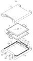
- FIG. 2 is a perspective view illustrating a secondary battery cartridge according to an embodiment of the present disclosure.
- FIG. 3 is an exploded partial perspective view of FIG. 2 .
- FIGS. 4 to 7 are perspective views illustrating components of the secondary battery cartridge of FIG. 2 .
- FIG. 8 is a cross-sectional view of the secondary battery cartridge of FIG. 2 .
- FIG. 9 is an enlarged view of a primary part of FIG. 8 .
- FIG. 10 is a perspective view schematically illustrating a configuration of a battery module according to an embodiment of the present disclosure.
- FIG. 2 is a perspective view illustrating a secondary battery cartridge according to an embodiment of the present disclosure.
- FIG. 3 is an exploded partial perspective view of FIG. 2 .
- FIGS. 4 to 7 are perspective views illustrating components of the secondary battery cartridge of FIG. 2 .
- the secondary battery cartridge 100 includes a battery storing box 110 , a sensing unit 120 , and a cover unit 130 .
- the cartridge 100 since the cartridge 100 has a sealed structure except a gas outlet 133 , a related art outer case entirely sealing assembled cartridges 100 is not required and thus the volume of a battery module 10 or a battery pack may be reduced, and also manufacturing costs may be reduced.
- the battery storing box 110 is used for stacking a plurality of secondary batteries B, holds the secondary battery B to prevent movement thereof, is configured such that the secondary batteries B are mutually stacked, and thus guide assembly of the secondary batteries B.
- the plurality of secondary batteries B may be pouch type secondary batteries B.
- Each pouch type secondary battery may have an electrode lead L.
- the electrode lead L may include two electrode leads L (an anode lead and a cathode lead) protruding and extending in one direction or two directions.
- two pouch type secondary batteries may be arranged in a layer form inside the battery storing box 110 .
- An electrode lead L of one of the secondary batteries B may be fixed to an electrode lead L of the other of the secondary batteries B through welding. Through this configuration, the secondary batteries B may be electrically connected inside the battery storing box 110 .
- the battery storing box 110 may include an upper case 111 and a lower case 112 .
- the upper case 111 and the lower case 112 may be provided such that they are coupled to and separated from each other.
- the battery storing box 110 may be configured such that two pouch type secondary batteries B are stacked in the lower case 112 and then the lower case 112 is covered by the upper case 111 .
- the upper case 111 and the lower case 112 may be coupled as one body by a rod-type fastening member, for example, a long bolt 140 , which may be inserted into a through hole H vertically passing through corners of the upper case 111 and the lower case 112 .
- the upper case 111 and the lower case 112 may be coupled to each other by a hooking method.
- the stored secondary battery B may be sealed inside the battery storing box 110 .
- an electrode lead L of the secondary battery B may be exposed to outside through a slot 116 (see FIG. 4 ) formed at the opposite lateral sides of the battery storing box 110 .
- the electrode lead L of the secondary battery B may be electrically connected to the sensing unit 120 .
- the battery storing box 110 includes a battery accommodation space 114 , a flow channel 115 a , the slot 116 , and a venting hole 117 .
- the battery accommodation space 114 and the flow channel 115 a are provided together inside the battery storing box 110 .
- the flow channel 115 a is partitioned from the battery accommodation space 114 inside the battery storing box 110 and has a hallow structure.
- the slot 116 and the venting hole 117 may be provided to the opposite lateral sides of the battery storing box 110 .
- the slot 116 communicates with the battery accommodation space 114
- the venting hole 117 communicates with the flow channel 115 a.
- the battery accommodation space 114 , the flow channel 115 a , the slot 116 , and the venting hole 117 may be formed by mutual coupling of the upper case 111 and the lower case 112 .
- the upper case 111 and the lower case 112 have a structure in which the battery accommodation space 114 , the flow channel 115 a , the slot 116 , and the venting hole 117 are symmetric with respect to a coupling surface. That is, the upper case 111 and the lower case 112 include a part of a shape of the battery accommodation space 114 , the flow channel 115 a , the slot 116 , and the venting hole 117 .
- an inner structure of the battery storing box 110 is described in detail.
- the lower case 112 includes a battery storing unit 114 and a case peripheral unit 115 .
- the battery storing unit 114 seats one or more secondary batteries B therein and forms the battery accommodation space.
- the secondary battery B may be arranged in the battery storing unit 114 . Therefore, the battery storing unit 114 may be designed in a size corresponding to the width and the length of the secondary battery B.
- the battery storing unit 114 may include a metallic material such as aluminum having high heat conductivity.
- a cell body of the secondary battery B may be arranged to directly contact the battery storing unit 114 .
- a heat dissipation effect of the secondary battery B may be increased by configuring the battery storing unit 114 with aluminum.
- the case peripheral unit 115 configures a wall along a circumferential direction of the battery storing unit 114 .
- the case peripheral unit 115 may be manufactured in a quadrangular frame form surrounding the battery storing unit 114 .
- the upper case 111 and the lower case 112 may be coupled such that upper surfaces of the case peripheral units 115 face each other.
- the upper surface of the case peripheral unit 115 corresponds to the coupling surface of the battery storing box 110 .
- a step difference unit 115 d lower than the upper surface is provided to the opposite lateral sides corresponding to a short side of the case peripheral unit 115 .
- the electrode lead L of the secondary battery B may be put on the step difference unit 115 d . Since the step difference unit 115 d of the lower case 112 and the step difference unit 115 d of the upper case 111 are symmetrically aligned with respect to the coupling surface, the slot 116 of the battery storing box 110 may be formed.
- the case peripheral unit 115 includes a first groove 115 a .
- the first groove 115 a is a part forming the flow channel of the battery storing box 110 .
- the first groove 115 a of the lower case 112 and the first groove 115 a of the upper case 111 are symmetrically aligned with respect to the coupling surface to form the flow channel.
- the first groove 115 a may be collapsed by a preset depth from the upper surface of the case peripheral unit 115 , and as illustrated in FIG. 5 , may extend from one lateral side of the case peripheral unit 115 to the other lateral side along a long side of the case peripheral unit 115 .
- the first groove 115 a may be divided into two parts with respect to the step difference unit 115 d and the divided two first grooves 115 a may respectively pass through opposite long sides of the case peripheral unit 115 .
- gases generated from the secondary battery B may be discharged to outside more effectively and swiftly than a case where one first groove 115 a is provided.
- the case peripheral unit 115 may further include a second groove 115 b and a third groove 115 c .
- the second groove 115 b may be collapsed by a preset depth from the upper surface of the case peripheral unit 115 and may extend from one lateral side of the case peripheral unit 115 to the other lateral side along the long side of the case peripheral unit 115 .
- the second groove 115 b may be formed to an outer side with respect to the first groove 115 a .
- a sealing member 113 a may be provided to the second groove 115 b.
- the sealing member 113 a when the lower case 112 is coupled to the upper case 111 , the sealing member 113 a is provided to a space prepared by alignment of the second groove 115 b of the lower case 112 and the second groove 115 b of the upper case 111 , and thus a sealing characteristic between the lower case 112 and the upper case 111 may be improved. Therefore, gas leakage between coupling surfaces of the lower case 112 and the upper case 111 may be prevented.
- a gasket including a rubber material such as ethylene propylene diene monomer (EPDM) may be used.
- the third groove 115 c may be collapsed by a preset depth from an outer wall surface of the opposite lateral surfaces of the case peripheral unit 115 , connected to the second groove 115 b , and formed in a form surrounding the step difference unit 115 d and an outer side of a point at which the first groove 115 a ends. Therefore, when the lower case 112 is coupled to the upper case 111 , a quadrangular frame-shaped intaglio may be formed on the opposite lateral sides of the battery storing box 110 by the third groove 115 c of the lower case 112 and the third groove 115 c of the upper case 111 .
- a sealing member 113 b may be further provided to the third groove 115 c .
- the sealing member 113 b provided to the third groove 115 c is a configuration for increasing adhesive force between the lateral sides of the battery storing box 110 and the cover unit 130 .
- the sealing member 113 b fit into the third groove 115 c may stick to an open end of an inner cover 132 of the cover unit 130 , and prevents gases flowing through the slot 116 and the venting hole 117 from leaking to outside.
- the present embodiment implements a continuous sealing line and simplifies an assembly process by manufacturing the sealing member 113 a fit into the second groove 115 b and the sealing member 113 b fit into the third groove 115 c as one body.
- an assembly finger 115 e protruding further than other parts and including a through hole H may be provided to a corner region of the case peripheral unit 115 .
- a rod-type fastening member may be inserted into and may pass through the through hole H.
- the upper case 111 may be coupled to the lower case 112 when the long bolt 140 is fit into the assembly finger 115 e .
- the plurality of cartridges 100 may be connected and assembled as one body by using one long bolt 140 .
- the sensing unit 120 is electrically connected to the electrode lead L of the secondary battery B, and connected to another secondary battery cartridge 100 or an external device by connection between the terminals 124 .
- the sensing unit 120 may be mounted on at least one lateral side of the battery storing box 110 .
- a configuration of the sensing unit 120 may change according to a kind of the secondary battery depending on the location of the electrode lead L.
- the sensing unit 120 may be mounted on only one lateral side of the battery storing box 110 .
- the sensing units 120 may be respectively mounted on the opposite lateral sides of the battery storing box 110 .
- the sensing unit 120 includes a pair of brackets 121 and a sensing block 122 .
- the pair of brackets 121 may be coupled to the lateral outer wall of the battery storing box 110 such that the brackets 121 are spaced apart from each other with the slot 116 therebetween.
- the bracket 121 may be assembled, by using a bolt, to the lateral outer wall of the battery storing box 110 .
- the sensing block 122 is connected to the pair of brackets 121 such that the sensing block 122 is located in front of the slot 116 .
- the sensing block 122 and the pair of brackets 121 may be formed as one body.
- the sensing block 122 protrudes from the bracket 121 and has a width of a central part thereof narrower than the widths of opposite ends thereof such that two lead-passing holes 123 are provided between the central part thereof and the pair of brackets 121 .
- the electrode lead L of the secondary battery B may pass through the lead-passing hole 123 , and the electrode lead L of the secondary battery B that has passed through the lead-passing hole 123 may be fixed to a body of the sensing block 122 by using welding, etc. Also, the terminal 124 may be further coupled to the sensing block 122 .
- the terminal 124 may pass through the cover unit 130 and be exposed to outside.
- an O-ring may be further fit to the periphery of the terminal 124 in order to prevent gas leakage between the terminal 124 and a through hole of the cover unit 130 .
- the cover unit 130 shields the slot 116 and the venting hole 117 of the battery storing box 110 and protects the sensing unit 120 .
- the cover unit 130 may be mounted on the opposite lateral sides of the battery storing box 110 to cover the slot 116 , the venting hole 117 , and the sensing unit 120 .
- the cover unit 130 includes the inner cover 132 and an outer cover 131 .
- the cover unit 130 may have a double structure.
- the outer cover 131 is provided to be suitable for a width between the assembly fingers 115 e of the battery storing box 110
- the inner cover 132 is provided to have the open end corresponding to the quadrangular frame intaglio-shaped third groove 115 c .
- the sealing member 113 b is provided between the open end of the inner cover 132 and the third groove 115 c .
- the inner cover 132 shields the slot 116 and the venting hole 117 .
- a gas leakage prevention effect may be raised even more and self mechanical rigidity may be increased by configuring the cover unit 130 with the double structure.
- the cover units 130 are mounted, one by one, on the opposite lateral sides of the battery storing box 110 , and the gas outlet 133 is provided to at least one of the cover units 130 .
- the gas outlets 133 may be provided to both two cover units 130 , it is preferable that the gas outlet 133 is provided to one of the cover units 130 in order to unify a gas discharge path.
- the gas outlet 133 may communicate with the inner cover 132 . Therefore, in the secondary battery cartridge 100 according to the present embodiment, gases are discharged to outside through only the gas outlet 133 .
- the gases introduced to the inner cover 132 to which the gas outlet 133 is provided may be discharged to outside through the gas outlet 133 .
- Gases introduced to the inner cover 132 on the opposite side to which the gas outlet 133 is not provided may be likewise introduced to the inside of the inner cover 132 through the slot 116 , and then may be sucked into the opposite venting hole 117 adjacent to the slot 116 .
- flow of the gases may be directed toward the gas outlet 133 due to a pressure difference.
- the gases may come out of the opposite venting hole 117 by way of the flow channel formed in the case peripheral unit 115 of the battery storing box 110 , and may be discharged to the outside of the secondary battery cartridge 100 through the gas outlet 133 .
- the secondary battery cartridge 100 having the above configuration according to the present disclosure may not only serve as a stacking guide of the secondary battery B but also discharge gases generated when the secondary battery B malfunctions on a cartridge basis to a specific path. Therefore, when the secondary battery cartridge 100 is utilized, a pack case (for example, the pack case illustrated in FIG. 1 ) among components of the battery module 10 or the battery pack may be omitted.
- a pack case for example, the pack case illustrated in FIG. 1
- components of the battery module 10 or the battery pack may be omitted.
- FIG. 10 is a perspective view schematically illustrating a configuration of a battery module 10 according to an embodiment of the present disclosure.
- the battery module 10 may be configured by stacking a plurality of secondary battery cartridges 100 .
- the secondary battery cartridges 100 may be stacked in a layer arrangement such that the gas outlets 133 face the same direction.
- the stacked bodies of the secondary battery cartridges 100 may be assembled as one body by using the long bolt 140 .
- the long bolt 140 may be inserted into the through hole H of the assembly finger 115 e provided to the corner region of each secondary battery cartridge 100 .
- terminals 124 may be connected by using a bus bar or a cable (not shown), etc. That is, the secondary batteries B stored in respective cartridges 100 may be electrically connected by connection of the terminals 124 .
- a manifold 200 may be coupled to the gas outlets 133 of the respective cartridges 100 .
- the manifold 200 collects gases discharged from the inside of the respective cartridges 100 to one place.
- the manifold 200 may be connected to an exhaust line (not shown).
- the respective cartridges 100 have a sealed structure and a flow channel which may discharge gases is designed therein. Therefore, an external case which was required for discharging gases in a related art may be omitted.
- the battery pack according to the present disclosure may include one or more battery modules according to the present disclosure. Also, the battery pack according to the present disclosure may further include various apparatuses for controlling charging/discharging of the battery module, for example, a battery management system (BMS), a current sensor, a fuse, etc. in addition to the battery module.
- BMS battery management system
- the battery module according to the present disclosure is applicable to an automobile such as an electric automobile or a hybrid automobile. That is, an automobile according to the present disclosure may include one or more battery modules according to the present disclosure.
- the present disclosure relates to a secondary battery cartridge, and particularly, is applicable to a battery module including the secondary battery cartridge, and a device driven by the battery module, for example, an electric automobile related industry.
Landscapes
- Chemical & Material Sciences (AREA)
- Chemical Kinetics & Catalysis (AREA)
- Electrochemistry (AREA)
- General Chemical & Material Sciences (AREA)
- Engineering & Computer Science (AREA)
- Manufacturing & Machinery (AREA)
- Inorganic Chemistry (AREA)
- Battery Mounting, Suspending (AREA)
- Gas Exhaust Devices For Batteries (AREA)
Applications Claiming Priority (3)
| Application Number | Priority Date | Filing Date | Title |
|---|---|---|---|
| KR10-2015-0148075 | 2015-10-23 | ||
| KR1020150148075A KR102014462B1 (ko) | 2015-10-23 | 2015-10-23 | 이차 전지용 카트리지 및 이를 포함하는 배터리 모듈 |
| PCT/KR2016/009667 WO2017069397A1 (ko) | 2015-10-23 | 2016-08-30 | 이차 전지용 카트리지 및 이를 포함하는 배터리 모듈 |
Publications (2)
| Publication Number | Publication Date |
|---|---|
| US20180254444A1 US20180254444A1 (en) | 2018-09-06 |
| US10411233B2 true US10411233B2 (en) | 2019-09-10 |
Family
ID=58557714
Family Applications (1)
| Application Number | Title | Priority Date | Filing Date |
|---|---|---|---|
| US15/559,710 Active 2036-12-17 US10411233B2 (en) | 2015-10-23 | 2016-08-30 | Secondary battery cartridge and battery module comprising same |
Country Status (7)
| Country | Link |
|---|---|
| US (1) | US10411233B2 (pl) |
| EP (1) | EP3270438B1 (pl) |
| JP (1) | JP6549307B2 (pl) |
| KR (1) | KR102014462B1 (pl) |
| CN (1) | CN107534110B (pl) |
| PL (1) | PL3270438T3 (pl) |
| WO (1) | WO2017069397A1 (pl) |
Cited By (6)
| Publication number | Priority date | Publication date | Assignee | Title |
|---|---|---|---|---|
| US20210276405A1 (en) * | 2020-03-06 | 2021-09-09 | Honda Motor Co., Ltd. | Battery pack |
| EP4007052A1 (en) * | 2020-11-30 | 2022-06-01 | SK Innovation Co., Ltd. | Battery sub-packing unit |
| US11742534B2 (en) | 2018-10-08 | 2023-08-29 | Samsung Sdi Co., Ltd. | Battery pack |
| US11742537B2 (en) | 2018-10-17 | 2023-08-29 | Samsung Sdi Co., Ltd. | Battery pack |
| US11749848B2 (en) | 2018-10-08 | 2023-09-05 | Samsung Sdi Co., Ltd. | Battery pack including a cover and a sealing member |
| EP4664632A1 (en) * | 2024-06-12 | 2025-12-17 | Samsung SDI Co., Ltd. | Battery pack |
Families Citing this family (25)
| Publication number | Priority date | Publication date | Assignee | Title |
|---|---|---|---|---|
| KR102096983B1 (ko) * | 2017-09-08 | 2020-04-03 | 주식회사 엘지화학 | 벤팅 가스를 이용하여 커넥터를 파단시키는 구조를 갖는 배터리 모듈 |
| KR102058197B1 (ko) * | 2017-09-18 | 2020-01-22 | 주식회사 엘지화학 | 배터리 케이스와 이를 포함하는 배터리 팩 및 자동차 |
| KR102328738B1 (ko) * | 2017-09-20 | 2021-11-17 | 주식회사 엘지에너지솔루션 | 과충전 시험 장치 |
| KR102033101B1 (ko) * | 2017-09-27 | 2019-10-16 | 주식회사 엘지화학 | 배터리 모듈, 이를 포함하는 배터리 팩 및 자동차 |
| KR102330378B1 (ko) | 2018-04-20 | 2021-11-22 | 주식회사 엘지에너지솔루션 | 디개싱 유로를 구비한 배터리 팩 |
| EP3576181A1 (en) * | 2018-05-28 | 2019-12-04 | PMB Defence Engineering Pty Ltd | Submarine battery bank |
| CN110380107A (zh) * | 2019-08-21 | 2019-10-25 | 连云港德立信电子科技有限公司 | 超薄锂电池 |
| JP7567161B2 (ja) * | 2019-09-30 | 2024-10-16 | 日本ケミコン株式会社 | 電源ユニットおよびその製造方法 |
| CN112692849A (zh) * | 2019-10-23 | 2021-04-23 | 北京配天技术有限公司 | 机器人控制柜以及机器人系统 |
| JP7445188B2 (ja) * | 2019-10-29 | 2024-03-07 | 三菱自動車工業株式会社 | 電池モジュール |
| KR102844872B1 (ko) | 2020-04-17 | 2025-08-08 | 주식회사 엘지에너지솔루션 | 화염 배출 방지 구조를 갖는 배터리 모듈, 이를 포함하는 배터리 팩, 자동차 및 전력 저장 시스템 |
| KR102922130B1 (ko) | 2020-04-29 | 2026-02-02 | 주식회사 엘지에너지솔루션 | 전지팩 및 이를 포함하는 디바이스 |
| KR102922131B1 (ko) | 2020-04-29 | 2026-02-02 | 주식회사 엘지에너지솔루션 | 전지팩 및 이를 포함하는 디바이스 |
| KR102959445B1 (ko) * | 2020-05-25 | 2026-04-29 | 주식회사 엘지에너지솔루션 | 배터리 셀 이송 장치 |
| CN114788082B (zh) * | 2020-07-10 | 2023-12-12 | 宁德时代新能源科技股份有限公司 | 泄压机构、电池盒、电池单体、电池、制备方法和装置 |
| JP7585460B2 (ja) * | 2020-08-13 | 2024-11-18 | エルジー エナジー ソリューション リミテッド | 絶縁冷却液を用いた冷却構造を有するバッテリーモジュール、それを含むバッテリーパック及び自動車 |
| KR102856138B1 (ko) * | 2020-11-16 | 2025-09-04 | 주식회사 엘지에너지솔루션 | 절연유를 이용한 냉각 구조를 갖는 배터리 모듈, 그리고 이를 포함하는 배터리 팩 및 자동차 |
| US12603383B2 (en) * | 2020-11-18 | 2026-04-14 | Ford Global Technologies, Llc | Traction battery pack venting systems with enclosure assembly integrated vent exhaust channels |
| KR20220075711A (ko) * | 2020-11-30 | 2022-06-08 | 에스케이온 주식회사 | 배터리 모듈 |
| KR102795087B1 (ko) * | 2021-01-11 | 2025-04-10 | 주식회사 엘지에너지솔루션 | 배터리 모듈, 배터리 팩, 및 자동차 |
| WO2022224866A1 (ja) * | 2021-04-22 | 2022-10-27 | 住友電気工業株式会社 | フレキシブルプリント回路基板及びフレキシブルプリント回路基板の製造方法 |
| CN113324691A (zh) * | 2021-05-28 | 2021-08-31 | 中车齐齐哈尔车辆有限公司 | 一种压力传感装置 |
| WO2023121102A1 (ko) * | 2021-12-24 | 2023-06-29 | 주식회사 엘지에너지솔루션 | 안전성이 강화된 배터리 어셈블리 |
| KR102676180B1 (ko) * | 2022-04-05 | 2024-06-19 | 주식회사 엘지에너지솔루션 | 각형 이차전지 |
| KR20240175383A (ko) * | 2023-06-13 | 2024-12-20 | 주식회사 엘지에너지솔루션 | 이차전지 |
Citations (12)
| Publication number | Priority date | Publication date | Assignee | Title |
|---|---|---|---|---|
| JP2005322434A (ja) | 2004-05-06 | 2005-11-17 | Toyota Motor Corp | 電池モジュールと組電池 |
| EP1744383A1 (en) | 2004-03-31 | 2007-01-17 | NEC Lamilion Energy, Ltd. | Electrical device with film covering, frame member, and housing system for electrical device with film covering |
| US20070122692A1 (en) * | 2003-06-03 | 2007-05-31 | Eastway Fair Company, Limited | Battery venting system |
| US20090274952A1 (en) * | 2006-12-14 | 2009-11-05 | Johnson Controls - Saf Advanced Power Solutions Llc | Battery module |
| US20090325042A1 (en) | 2008-06-30 | 2009-12-31 | Lg Chem, Ltd. | Battery Cell interconnect and Voltage Sensing Assembly and Method for Coupling a Battery Cell Assembly Thereto |
| JP2010165686A (ja) | 2010-03-05 | 2010-07-29 | Toyota Motor Corp | 蓄電モジュールと該モジュール用枠体 |
| US20120276430A1 (en) | 2011-04-28 | 2012-11-01 | Gm Blobal Technology Operations Llc | Integrated sense lead module frame |
| JP2013073754A (ja) | 2011-09-27 | 2013-04-22 | Toyota Industries Corp | 車載バッテリの冷却構造 |
| US20130183544A1 (en) | 2012-01-16 | 2013-07-18 | Lithium Energy Japan | Battery module and power source unit |
| KR20130126159A (ko) | 2012-05-11 | 2013-11-20 | 에스케이이노베이션 주식회사 | 냉각 유로 관통형 이차전지모듈 |
| KR20140024579A (ko) | 2012-08-20 | 2014-03-03 | 에스케이이노베이션 주식회사 | 전지모듈 어셈블리 및 그 제조방법 |
| KR20150118375A (ko) | 2014-04-14 | 2015-10-22 | 주식회사 엘지화학 | 배터리 모듈 및 이를 포함하는 배터리 팩 |
Family Cites Families (3)
| Publication number | Priority date | Publication date | Assignee | Title |
|---|---|---|---|---|
| JP5323645B2 (ja) * | 2009-11-09 | 2013-10-23 | 日立ビークルエナジー株式会社 | 蓄電デバイス、蓄電モジュールおよび自動車 |
| JP5663282B2 (ja) * | 2010-12-01 | 2015-02-04 | カルソニックカンセイ株式会社 | 組電池 |
| KR101599832B1 (ko) * | 2014-04-14 | 2016-03-04 | 주식회사 유라테크 | 배기 센서 통합 모듈 및 정화 장치 제어방법 |
-
2015
- 2015-10-23 KR KR1020150148075A patent/KR102014462B1/ko active Active
-
2016
- 2016-08-30 PL PL16857655T patent/PL3270438T3/pl unknown
- 2016-08-30 WO PCT/KR2016/009667 patent/WO2017069397A1/ko not_active Ceased
- 2016-08-30 CN CN201680022425.XA patent/CN107534110B/zh active Active
- 2016-08-30 JP JP2018505446A patent/JP6549307B2/ja active Active
- 2016-08-30 EP EP16857655.1A patent/EP3270438B1/en active Active
- 2016-08-30 US US15/559,710 patent/US10411233B2/en active Active
Patent Citations (16)
| Publication number | Priority date | Publication date | Assignee | Title |
|---|---|---|---|---|
| US20070122692A1 (en) * | 2003-06-03 | 2007-05-31 | Eastway Fair Company, Limited | Battery venting system |
| EP1744383A1 (en) | 2004-03-31 | 2007-01-17 | NEC Lamilion Energy, Ltd. | Electrical device with film covering, frame member, and housing system for electrical device with film covering |
| JP2005322434A (ja) | 2004-05-06 | 2005-11-17 | Toyota Motor Corp | 電池モジュールと組電池 |
| US20090274952A1 (en) * | 2006-12-14 | 2009-11-05 | Johnson Controls - Saf Advanced Power Solutions Llc | Battery module |
| US20090325042A1 (en) | 2008-06-30 | 2009-12-31 | Lg Chem, Ltd. | Battery Cell interconnect and Voltage Sensing Assembly and Method for Coupling a Battery Cell Assembly Thereto |
| JP2010165686A (ja) | 2010-03-05 | 2010-07-29 | Toyota Motor Corp | 蓄電モジュールと該モジュール用枠体 |
| US20120276430A1 (en) | 2011-04-28 | 2012-11-01 | Gm Blobal Technology Operations Llc | Integrated sense lead module frame |
| JP2013073754A (ja) | 2011-09-27 | 2013-04-22 | Toyota Industries Corp | 車載バッテリの冷却構造 |
| US20130183544A1 (en) | 2012-01-16 | 2013-07-18 | Lithium Energy Japan | Battery module and power source unit |
| JP2013168355A (ja) | 2012-01-16 | 2013-08-29 | Lithium Energy Japan:Kk | 組電池及び電源装置 |
| KR20130126159A (ko) | 2012-05-11 | 2013-11-20 | 에스케이이노베이션 주식회사 | 냉각 유로 관통형 이차전지모듈 |
| US20150099146A1 (en) | 2012-05-11 | 2015-04-09 | Sk Innovation Co., Ltd. | Secondary battery module having through type cool channel |
| KR20140024579A (ko) | 2012-08-20 | 2014-03-03 | 에스케이이노베이션 주식회사 | 전지모듈 어셈블리 및 그 제조방법 |
| US20150214569A1 (en) | 2012-08-20 | 2015-07-30 | Sk Innovation Co., Ltd. | Battery module assembly and manufacturing method therefor |
| KR20150118375A (ko) | 2014-04-14 | 2015-10-22 | 주식회사 엘지화학 | 배터리 모듈 및 이를 포함하는 배터리 팩 |
| US20170033419A1 (en) | 2014-04-14 | 2017-02-02 | Lg Chem, Ltd. | Battery module and battery pack including same |
Non-Patent Citations (1)
| Title |
|---|
| International Search Report issued in PCT/KR2016/009667 (PCT/ISA/210), dated Dec. 27, 2016. |
Cited By (10)
| Publication number | Priority date | Publication date | Assignee | Title |
|---|---|---|---|---|
| US11742534B2 (en) | 2018-10-08 | 2023-08-29 | Samsung Sdi Co., Ltd. | Battery pack |
| US11749848B2 (en) | 2018-10-08 | 2023-09-05 | Samsung Sdi Co., Ltd. | Battery pack including a cover and a sealing member |
| US11742537B2 (en) | 2018-10-17 | 2023-08-29 | Samsung Sdi Co., Ltd. | Battery pack |
| US12463271B2 (en) | 2018-10-17 | 2025-11-04 | Samsung Sdi Co., Ltd. | Battery pack |
| US20210276405A1 (en) * | 2020-03-06 | 2021-09-09 | Honda Motor Co., Ltd. | Battery pack |
| US11584212B2 (en) * | 2020-03-06 | 2023-02-21 | Honda Motor Co., Ltd. | Battery pack having overlapping battery modules |
| EP4007052A1 (en) * | 2020-11-30 | 2022-06-01 | SK Innovation Co., Ltd. | Battery sub-packing unit |
| US11996574B2 (en) | 2020-11-30 | 2024-05-28 | Sk On Co., Ltd. | Battery sub-packing unit |
| US12586854B2 (en) | 2020-11-30 | 2026-03-24 | Sk On Co., Ltd. | Battery sub-packing unit |
| EP4664632A1 (en) * | 2024-06-12 | 2025-12-17 | Samsung SDI Co., Ltd. | Battery pack |
Also Published As
| Publication number | Publication date |
|---|---|
| US20180254444A1 (en) | 2018-09-06 |
| PL3270438T3 (pl) | 2020-06-29 |
| KR102014462B1 (ko) | 2019-08-26 |
| EP3270438B1 (en) | 2020-01-15 |
| JP6549307B2 (ja) | 2019-07-24 |
| WO2017069397A1 (ko) | 2017-04-27 |
| KR20170047687A (ko) | 2017-05-08 |
| EP3270438A4 (en) | 2018-04-18 |
| EP3270438A1 (en) | 2018-01-17 |
| JP2018526774A (ja) | 2018-09-13 |
| CN107534110A (zh) | 2018-01-02 |
| CN107534110B (zh) | 2020-07-28 |
Similar Documents
| Publication | Publication Date | Title |
|---|---|---|
| EP3270438B1 (en) | Secondary battery cartridge and battery module comprising same | |
| EP3699976B1 (en) | Battery pack provided with degassing flow channel | |
| KR102311075B1 (ko) | 팩 하우징을 포함하는 배터리 팩 | |
| EP3567670B1 (en) | Battery module | |
| EP4203163A1 (en) | Battery module, battery pack comprising same, and automobile | |
| US10381622B2 (en) | Battery pack | |
| US10608219B2 (en) | Integrated cartridge and battery pack comprising same | |
| KR101610876B1 (ko) | 이차 전지용 프레임 및 이를 포함하는 배터리 모듈 | |
| US20180248237A1 (en) | Battery pack | |
| US12266777B2 (en) | Battery module including internal plate | |
| JP6627682B2 (ja) | 電池パック | |
| EP3780253A1 (en) | Battery module comprising module housing | |
| KR20150118375A (ko) | 배터리 모듈 및 이를 포함하는 배터리 팩 | |
| JP2015505142A (ja) | バッテリモジュールハウジングとバッテリセルを備えるバッテリモジュール | |
| KR20150025308A (ko) | 냉매 및 배기 가스의 혼합을 방지하는 구조를 포함하는 전지모듈 | |
| US12562430B2 (en) | Battery module, and battery pack and automobile including same | |
| KR101813234B1 (ko) | 이차 전지용 셀 커버 및 이를 포함하는 배터리 모듈 | |
| CN110199407B (zh) | 包括吸收层和绝缘膜的电池外壳 | |
| KR102216115B1 (ko) | 배터리 모듈, 이러한 배터리 모듈을 포함하는 배터리 팩 및 이러한 배터리 팩을 포함하는 자동차 | |
| KR102800697B1 (ko) | 배터리, 배터리 모듈, 배터리 팩, 및 전기 차량 |
Legal Events
| Date | Code | Title | Description |
|---|---|---|---|
| FEPP | Fee payment procedure |
Free format text: ENTITY STATUS SET TO UNDISCOUNTED (ORIGINAL EVENT CODE: BIG.); ENTITY STATUS OF PATENT OWNER: LARGE ENTITY |
|
| AS | Assignment |
Owner name: LG CHEM, LTD., KOREA, REPUBLIC OF Free format text: ASSIGNMENT OF ASSIGNORS INTEREST;ASSIGNORS:YOON, DOO-HAN;KIM, SUNG-JONG;SEONG, JUN-YEOB;SIGNING DATES FROM 20170611 TO 20170613;REEL/FRAME:043653/0982 |
|
| STPP | Information on status: patent application and granting procedure in general |
Free format text: NON FINAL ACTION MAILED |
|
| STPP | Information on status: patent application and granting procedure in general |
Free format text: RESPONSE TO NON-FINAL OFFICE ACTION ENTERED AND FORWARDED TO EXAMINER |
|
| STPP | Information on status: patent application and granting procedure in general |
Free format text: PUBLICATIONS -- ISSUE FEE PAYMENT VERIFIED |
|
| STCF | Information on status: patent grant |
Free format text: PATENTED CASE |
|
| AS | Assignment |
Owner name: LG ENERGY SOLUTION, LTD., KOREA, REPUBLIC OF Free format text: ASSIGNMENT OF ASSIGNORS INTEREST;ASSIGNOR:LG CHEM, LTD.;REEL/FRAME:058295/0068 Effective date: 20211027 |
|
| MAFP | Maintenance fee payment |
Free format text: PAYMENT OF MAINTENANCE FEE, 4TH YEAR, LARGE ENTITY (ORIGINAL EVENT CODE: M1551); ENTITY STATUS OF PATENT OWNER: LARGE ENTITY Year of fee payment: 4 |